EP3216333A2 - Tracteur agricole comprenant un véhicule tracteur et une remorque - Google Patents
Tracteur agricole comprenant un véhicule tracteur et une remorque Download PDFInfo
- Publication number
- EP3216333A2 EP3216333A2 EP16203238.7A EP16203238A EP3216333A2 EP 3216333 A2 EP3216333 A2 EP 3216333A2 EP 16203238 A EP16203238 A EP 16203238A EP 3216333 A2 EP3216333 A2 EP 3216333A2
- Authority
- EP
- European Patent Office
- Prior art keywords
- train
- trailer
- brake system
- towing vehicle
- transmission
- Prior art date
- Legal status (The legal status is an assumption and is not a legal conclusion. Google has not performed a legal analysis and makes no representation as to the accuracy of the status listed.)
- Granted
Links
Images
Classifications
-
- A—HUMAN NECESSITIES
- A01—AGRICULTURE; FORESTRY; ANIMAL HUSBANDRY; HUNTING; TRAPPING; FISHING
- A01B—SOIL WORKING IN AGRICULTURE OR FORESTRY; PARTS, DETAILS, OR ACCESSORIES OF AGRICULTURAL MACHINES OR IMPLEMENTS, IN GENERAL
- A01B59/00—Devices specially adapted for connection between animals or tractors and agricultural machines or implements
- A01B59/04—Devices specially adapted for connection between animals or tractors and agricultural machines or implements for machines pulled or pushed by a tractor
- A01B59/042—Devices specially adapted for connection between animals or tractors and agricultural machines or implements for machines pulled or pushed by a tractor having pulling means arranged on the rear part of the tractor
-
- B—PERFORMING OPERATIONS; TRANSPORTING
- B60—VEHICLES IN GENERAL
- B60T—VEHICLE BRAKE CONTROL SYSTEMS OR PARTS THEREOF; BRAKE CONTROL SYSTEMS OR PARTS THEREOF, IN GENERAL; ARRANGEMENT OF BRAKING ELEMENTS ON VEHICLES IN GENERAL; PORTABLE DEVICES FOR PREVENTING UNWANTED MOVEMENT OF VEHICLES; VEHICLE MODIFICATIONS TO FACILITATE COOLING OF BRAKES
- B60T13/00—Transmitting braking action from initiating means to ultimate brake actuator with power assistance or drive; Brake systems incorporating such transmitting means, e.g. air-pressure brake systems
- B60T13/02—Transmitting braking action from initiating means to ultimate brake actuator with power assistance or drive; Brake systems incorporating such transmitting means, e.g. air-pressure brake systems with mechanical assistance or drive
- B60T13/06—Transmitting braking action from initiating means to ultimate brake actuator with power assistance or drive; Brake systems incorporating such transmitting means, e.g. air-pressure brake systems with mechanical assistance or drive by inertia, e.g. flywheel
- B60T13/08—Overrun brakes
-
- B—PERFORMING OPERATIONS; TRANSPORTING
- B60—VEHICLES IN GENERAL
- B60T—VEHICLE BRAKE CONTROL SYSTEMS OR PARTS THEREOF; BRAKE CONTROL SYSTEMS OR PARTS THEREOF, IN GENERAL; ARRANGEMENT OF BRAKING ELEMENTS ON VEHICLES IN GENERAL; PORTABLE DEVICES FOR PREVENTING UNWANTED MOVEMENT OF VEHICLES; VEHICLE MODIFICATIONS TO FACILITATE COOLING OF BRAKES
- B60T7/00—Brake-action initiating means
- B60T7/12—Brake-action initiating means for automatic initiation; for initiation not subject to will of driver or passenger
- B60T7/20—Brake-action initiating means for automatic initiation; for initiation not subject to will of driver or passenger specially for trailers, e.g. in case of uncoupling of or overrunning by trailer
Definitions
- the present invention relates to an agricultural train with a towing vehicle and at least one trailer.
- Agricultural machines such as tractors are often used in addition to the pure field work for transport tasks in which, for example, transported to trailer loaded crop.
- One or more trailers are usually pulled by a towing vehicle and form a so-called agricultural train.
- trailers often have a so-called overrun brake, which acts on one or more axles.
- power-braked trailer are known in which with the operation of the brake system of the towing vehicle, such as the service brake, a brake signal is sent to the trailer brake system to operate them.
- the trailer brake system is actuated, but this is only possible in conjunction with actuated service brake of the tractor, so that must be driven against the actuated brakes of the towing vehicle and the trailer.
- the engine drag torque of the drive motor of this brake signal causing no braking of the trailer so that it pushes on the towing vehicle and there is a risk that the axles of the towing vehicle are overbrake, whereby the driving stability of the towing vehicle significantly reduced can be.
- An agricultural train comprises a towing vehicle, in particular a tractor, and at least one trailer coupled to the towing vehicle, wherein the at least one trailer has a first brake system, and wherein the towing vehicle, which is drivable via a drive motor cooperating with a transmission, a second brake system and a control device for controlling and / or regulating at least one brake system of the agricultural train has.
- the control device is designed and set up such that at least one brake system of the train can be actuated as a function of a determined overrun operation of the train and / or traction vehicle, wherein the overrun operation can be determined as a function of at least one operating parameter of the agricultural train.
- An overrun operation of the towing vehicle denotes the driving state of the towing vehicle, in which the drive motor of the towing vehicle is towed by the towing vehicle, ie the drive motor is held in rotary motion, for example during a rolling of the towing vehicle and / or agricultural train without actuation of an accelerator pedal.
- a delay of the agricultural train can be effected, which can be amplified, for example by an adjustment of the rotational speed of the drive motor of the towing vehicle and / or an adjustment of the gear ratio.
- the occurrence of an overrun operation can be determined reliably and without much delay.
- the overrun operation and / or its size, in particular the thrust torque can be determined by the control device based on at least one operating parameter.
- the control device at least one brake system of the agricultural train, such as a trailer brake system, operable to reduce the overrun or avoid.
- the control device for the actuation that is to say the control and / or regulation, of a brake system can generate a corresponding brake signal, which is sent to the brake system to be actuated.
- An inventive actuation of one or more brake systems of the agricultural train is carried out regardless of braking intervention of a possibly existing Anti-lock Braking System (ABS) and / or Electronic Stability Program (ESP), which may, for example, operate concurrently with the actuation of a brake system by the control device to avoid blocking the train's ground engaging means.
- ABS Anti-lock Braking System
- ESP Electronic Stability Program
- a limit value for the size of the overrun operation or the thrust torque can be stored, with which the respectively determined value can be compared.
- the overrun operation can be avoided by operating one or more brake systems or reduced to a value less than the limit.
- An actuation of one or more brake systems, in particular trailer brake systems, jointly or independently of each other by the control device may be such that a delay of the at least one trailer is equal to or greater than a delay of the towing vehicle, whereby the agricultural train is stretched.
- the delay is no longer generated only by the towing vehicle, but in addition, in particular predominantly, of the now braked at least one trailer.
- a first brake system of one or more trailers can be actuated independently of a second brake system of the towing vehicle.
- the driving safety of the agricultural train and in particular the towing vehicle can be improved.
- over-rotation and damage to the drive motor can be avoided.
- an operating parameter is a force acting on or on the towing vehicle, a moment, an engine speed, a transmission parameter, and / or a slip of ground engaging means of the train.
- the respective operating parameters can be determined by suitable sensors, for example, force, torque, pressure and / or rotational speed sensors, which can be connected to the control device.
- a force acting on the towing vehicle can be, for example, a force transmitted in a pushing operation from the trailer to the towing vehicle, in particular compressive force.
- a slip occurring at ground engaging means of the train, in particular in connection with occurring wheel forces and / or wheel torques can be determined and used as operating parameters, which can provide information about the power transmission of the tractor and / or trailer on the road.
- a transmission parameter is an output torque acting on the, in particular stepless, transmission and / or support torque.
- the transmission may be a power shift or continuously variable transmission.
- a continuously variable transmission may be in the form of a power-split hydraulic-mechanical, an electrical-mechanical, a purely hydraulic or a purely electrical transmission. Under a purely electrical transmission is an electrically controlled combination of a generator and at least one electric motor to understand.
- a hydraulic-mechanical power-split continuously variable transmission for example, be a so-called CVT transmission, which has a hydrostatic and a mechanical transmission part for power transmission.
- CVT is the abbreviation of the English technical term Continuously Variable Transmission.
- a hydraulic-mechanical continuously variable transmission can have hydrostats in a wide-angle construction.
- the output torque, its size and / or direction can be determined as a transmission parameter by means of suitable sensors.
- the determined output torque can be used to detect overrun, for example, depending on the direction of the output torque, and to control the first brake system depending on the size of the output torque in overrun mode.
- the support torque of the transmission can be determined as transmission parameters.
- the support torque which is dependent, for example, on a rotational speed of the drive motor, a transmission ratio and / or a transmission efficiency, can be determined by means of a characteristic, in particular a trailing characteristic, be determined.
- the output torque of a continuously variable transmission can be determined from a pressure difference in a hydrostatic partial transmission of the transmission.
- the continuously variable transmission can be designed in the form of a hydrostatic or hydraulic-mechanical continuously variable transmission.
- the hydraulic-mechanical continuously variable transmission in this case has a power split, in which, depending on the operating point, in each case part of the power is transmitted hydrostatically and / or mechanically.
- the power transmission can be effected by means of hydraulically connected hydrostats, in particular wide-angle design with increased pivoting range, a hydrostat acting as a pump and at least one further hydrostat as a motor.
- a pressure difference between two hydraulic lines connecting the hydrostatic units can be measured. From this pressure difference, the magnitude and / or the direction of the output torque can be reliably determined as an operating parameter in a cost-effective manner with knowledge of the swivel angle of the hydrostatic drives.
- the brake system of a trailer by the control device at determinable times and for a determinable duration can be actuated.
- a time and / or duration for actuating a brake system can be determined by the control device.
- parameters predetermined by the control device for example due to legal regulations, can be taken into account. These can be, for example, limit values for the size of the overrun operation, from which an actuation of a brake system takes place or specifications for the duration of the actuation. This allows effective operation of a brake system and an improvement in driving safety, since a braking intervention is better adaptable to different driving situations.
- the brake systems of the trailer are simultaneously and / or independently operable in a train with several braked trailers.
- the brake systems can independently, for example, be alternately actuated, whereby overloading of a brake system can be avoided.
- Ground engaging means support the trailer from the ground and may be in the form of wheels or caterpillar tracks which may be located on one or more axles of the trailer. It is advantageous that the braking intervention can be made more accurate and better adapted to the particular driving situation, whereby the driving safety in different driving situations can be further improved.
- an actuation of at least one brake system of the train takes place as a function of a number of trailers, the type of trailer, the respective trailer weight and / or the respective trailer braking power.
- These data can be stored in the control device and can be input manually or automatically, for example. This allows a better adapted to the particular driving situation operation of a brake system, which driving safety can be further increased.
- a cruise control system which is in signal communication with the control device.
- a speed of the towing vehicle thus also of the train, kept constant and / or automatically, for example, depending on location, are varied.
- the signal connection between the control device and the speed control system makes it possible to adapt a braking intervention to the driven and / or to be set speed. This has the advantage that an automatic actuation of one or more brake systems of the train to avoid a critical overrun operation is made possible even when driving with activated cruise control system.
- the invention relates to a method for actuating at least one brake system of an agricultural train with a towing vehicle, in particular a tractor, and at least one coupled to the towing vehicle trailer, wherein the at least one trailer has a first brake system, and wherein the towing vehicle, which with a one, in particular stepless, gear cooperating drive motor is driven, a second brake system and a control device for controlling and / or regulating at least one brake system of the agricultural train has.
- the control device actuates at least one brake system of the train as a function of a determined overrun operation of the train and / or towing vehicle, wherein the overrun operation is determined as a function of at least one operating parameter of the agricultural train.
- the occurrence of an overrun operation can be reliably determined, wherein the overrun operation and / or its size, in particular the thrust torque, can be determined by the control device based on at least one operating parameter.
- the control device at least one brake system of the agricultural train, such as a brake system of a trailer, operable to reduce the overrun or avoid.
- the control device for the actuation that is to say the control and / or regulation, of a brake system can generate a corresponding brake signal, which is sent to the brake system to be actuated.
- the driving safety of the agricultural train and in particular the towing vehicle can be improved.
- the agricultural train is braked solely by the drag torque of the drive motor, over-rotation and damage to the drive train and / or the drive motor can be avoided.
- an operating parameter used is a force acting on or on the towing vehicle, a torque, an engine speed, a transmission parameter such as an output torque and / or support torque, and / or a slip of ground engagement means of the train.
- the respective operating parameters can be determined by means of respectively suitable sensors, for example force, torque, pressure, direction of rotation and / or rotational speed sensors. It is advantageous that by determining the overrun operation and / or its size based on one or more operating parameters, an operation of a brake system can be made more reliable and accurate.
- a transmission parameter in the form of an output torque acting on a hydraulic-mechanical continuously variable transmission is determined from a pressure difference in a hydrostatic partial transmission of the transmission.
- the hydraulic-mechanical continuously variable transmission is power-split and has, in addition to a mechanical hydrostatic partial transmission for power transmission.
- In the hydrostatic partial transmission at least two hydrostatic units are arranged for variable power transmission, which are connected by means of hydraulic lines.
- a pressure difference between the lines for determining the overrun operation can be determined.
- the presence of a pushing operation can be determined from the direction of the output torque, which can also be determined from the pressure difference between the hydraulic lines between the hydrostats.
- This can be determined in particular by a reversal of the pressure difference, for example when the pressure of a first hydraulic line in the train operation is greater than the pressure of a second hydraulic line and this reverses, so that then the pressure in the second line is greater than in the first line and then overrun operation is present.
- the determined output torque then corresponds to the thrust torque.
- This offers the advantage that from the determined output torque, the presence of overrun operation can be determined and depending on the size of the output torque in overrun at least one, in particular the first, brake system can be controlled.
- Advantageous here is the use of existing components and / or a possible cost-effective retrofitting of individual sensors, which allows a simple and reliable determination of the operating parameters.
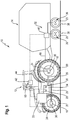
- FIG. 1 is shown as an example of an agricultural train 10, a towing vehicle 12 in the form of a tractor with a trailer 14 disposed thereon in a schematic side view.
- a towing vehicle 12 in the sense of the invention can be any agricultural working machine such as a forage harvester, a combine harvester or a tractor with or without attached implement.
- the towing vehicle 12 is supported relative to the ground by ground engagement means 20 in the form of wheels arranged respectively on a front axle 16 and a rear axle 18.
- the ground engaging means 20 may also be in the form of caterpillar drives.
- the tractor 12 has a drive motor 22 which is connected via a gear 24 to a drive train 26.
- the drive power can be controllably provided, which is required for example for fieldwork and / or road travel of the towing vehicle 12, wherein a torque generated by the drive motor 22 via the drive train 26 to the front and / or. or rear axle 16, 18 can be transmitted.
- the transmission ratio of the transmission 24 can be adjusted manually or automatically, especially under load.
- the transmission 24 may be formed in the form of a power shift transmission or a continuously variable transmission.
- the continuously variable transmissions there are different designs, so for example, the continuously variable transmission in the form of a power-split hydraulic-mechanical, an electric-mechanical, a purely hydraulic or a purely electric transmission can be formed.
- Tractor 12 shown has a continuously variable power split hydraulic-mechanical transmission 24 with a hydrostatic transmission part 48 and a mechanical transmission part 46 for power transmission, in which a part of the power hydrostatic and a part is transmitted mechanically.
- the hydrostatic partial transmission 48 the power transmission takes place via a first hydrostatic unit 28 and at least one hydraulically connected second hydrostatic unit 30, wherein a hydrostat 28, 30 acts as a pump and at least one further hydrostat 30, 28 as a motor.
- the power split in the transmission 24 via a planetary gear, whereby the force of the drive motor 22 in the mechanical drive of the ground engaging means 20 and the hydraulic of a continuously variable hydraulic pump, for example in the form of the first hydrostatic 28 is divided.
- the power transmitted to the first hydrostatic power 28 is transmitted hydraulically to the, in particular infinitely variable, second hydrostatic transmission 30, which acts as a hydraulic motor and provides the transmitted power of the hydrostatic subtransmission 48 for driving the wheels again.
- the transmission ratio of the transmission 24 is controlled via the continuously variable hydrostatic partial transmission 48.
- the hydrostat 28, 30 are formed in wide-angle design with increased swivel range. It would also be conceivable to arrange the hydrostats 28, 30 in a so-called back-to-back arrangement, in which the hydrostats 28, 30 are spatially arranged directly adjacent to one another, so that the two hydrostats 28, 30, for example within a housing, are directly hydraulically connected to one another are connected.
- At least one trailer 14 has a first brake system 32 and the traction vehicle 14 has a second brake system 34.
- the brake system 34 of the towing vehicle a service brake, which can be actuated by the operator, for example, by actuation of a brake pedal, a parking brake and / or an auxiliary brake.
- the brake systems 32, 34 may each be pneumatically, hydraulically, mechanically and / or electrically acting brake systems.
- the brake system 32 of a trailer 14 in each case comprises at least one brake 36 which acts on a trailer axle 38 and / or on a respective ground engaging means 20 of the trailer 14.
- the first brake system 32 can be controlled via at least one electronically controllable trailer brake valve 40, wherein the trailer brake valve 40 can be arranged on the trailer side or the towing vehicle side.
- brake line 66 a required for braking fluid, such as compressed air, passed from the tractor 12 to the trailer 14.
- the in FIG. 1 illustrated trailer 14 is connected by a drawbar to the towing vehicle 12 and has two trailer axles 38 disposed thereon on ground engaging means 20.
- At least one brake 36 is arranged on the trailer axles 38, wherein, for example, the trailer axles 38 and / or the ground engaging means 20 can be braked independently of one another.
- the first brake system 32 of the trailer 14 and the second brake system 34 of the towing vehicle 12 are each connected to a control device 42 of the towing vehicle 12 for controlling and / or regulating the brake systems 32, 34, which is arranged in a driver's cab 44 of the towing vehicle 12.
- the control device 42 is also connected to a cruise control system 68, whereby an operation of a brake system 32, 34 is feasible taking into account an automatic cruise control.
- the trailer brake valve 40 of the first brake system 32 can be controlled and regulated by the control device 42 for actuating at least one brake 36 of the trailer 14.
- At least one brake 36 is arranged on the front axle 16 and the rear axle 18 of the towing vehicle 12, as a result of which the respective axle 16, 18 and / or the respective ground engaging means 20 can be braked independently of one another.
- the control device 42 is furthermore set up for monitoring, controlling and / or regulating different functions of the agricultural train 10, in particular for controlling and / or regulating the drive motor 22, in particular the drive power of the drive motor 22, the transmission 24 and / or the drive train 26.
- the entire mass of the train 10 is braked by the drive axle 16, 18 of the towing vehicle 12. This can lead to an overbraking of the respective axle 16, 18 and a strong increase in the slip, so that the driving stability of the train 10 is reduced by pushing at least one trailer 14 and it can come to a buckling of the train 10 in the extreme case.
- the drag torque of the drive motor 22 can be over-turned and damaged.
- the control device 42 is designed and set up such that one or more brake systems 32, 34 of the train 10 can be actuated as a function of a determined overrun operation of the train 10 and / or traction vehicle 14, wherein the overrun operation is dependent on at least one operating parameter of the agricultural train 10 can be determined.
- a brake system 32, 34 of the train in particular the first brake system 32 of the trailer 14, a sliding of the trailer 14 can be reduced or avoided on the towing vehicle 12, whereby an impairment of the driving stability of the train 10 or overspeeding of the drive motor 22 avoided can be.
- the overrun of the train 10 is determined by the controller 42 based on at least one operating parameter, where an operating parameter is a force F acting on or on the towing vehicle 12, a moment, an engine speed n i , a transmission parameter, and / or a slip of ground engaging means 20 of the train can be 10.
- a force F acting on the towing vehicle 12 can be measured, for example, by means of a force measuring sensor on a coupling 56 of the towing vehicle 12, to which the trailer 14 is attached.
- a force measuring sensor on a coupling 56 of the towing vehicle 12, to which the trailer 14 is attached.
- an output torque M A of the transmission 24 is also available.
- the presence of a pushing operation on the basis of the direction of the output torque M A can be determined.
- the size of the determined output torque M A is in the overrun mode for control and / or regulation of a first brake system 32 usable, for example, as a basis for the strength and / or duration of their operation.
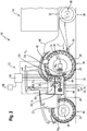
- FIG. 2 shown towing vehicle 12 in the form of a tractor has a continuously variable power-split transmission 24 with a mechanical partial transmission 46 and a hydraulic or hydrostatic partial transmission 48.
- an output torque M A is provided on an output shaft of the transmission 24, which output torque can be regulated as a function of an efficiency of the transmission 24 and of the transmission ratio.
- a planetary gear 50 For branching the incoming power into the transmission 24 of the drive motor 22, the transmission 22, a planetary gear 50, through which a part of the power via the mechanical part of gear 46 and another part via the hydrostatic partial transmission 48 is introduced into the drive train 26.
- the incoming power in the hydrostatic partial transmission 48 drives, for example, in particular direction of travel, the first Hydrostaten 28, which acts as a pump.
- This first hydrostat 28 is hydraulically connected via a first hydraulic line 52 and a second hydraulic line 54 to the second hydrostatic unit 54, which then acts as a motor, and also provides the power to the drive train 26.
- the steplessly adjustable hydrostats 28, 30, in particular in wide-angle construction, enable stepless control of the transmission ratio.
- the output torque M A of the hydraulic-mechanical continuously variable transmission 24, in particular its direction and / or size, can be determined by pressure sensors 58, 60, which are arranged on the hydraulic lines 52, 54, which hydraulically connect the hydrostatic units 28, 30.
- a first pressure sensor 58 is arranged on the first hydraulic line 52, and a second pressure sensor 60 on the second hydraulic line 54. If no pushing operation, so for example, the pressure P 1 in the first hydraulic line 54 is greater than the pressure P 2 in the second Hydraulic line 54. This pressure ratio is reversed when overrun occurs, so that in overrun mode, with unchanged direction of travel, the pressure P 2 is greater than the pressure P 1 .
- the size of the pressure difference corresponds to the size of the output torque M A at the output of the transmission 24.
- both the presence of a pushing operation and its size can be determined.
- the support torque Mst of the transmission 24 can be determined as a transmission parameter.
- the support torque Mst which is dependent on a speed of the drive motor 22, a gear ratio and / or a transmission efficiency, for example, can be determined by means of a characteristic, in particular a drag characteristic.
- the support torque Mst is the difference between the drive torque and the output torque M A of the transmission 24.
- the speed of the drive motor 22 by means of a first speed sensor 62, for example, on an input shaft of the transmission 24 can be measured.
- a second rotational speed sensor 64 on the output shaft of the transmission 24 the output speed can n a, and thus together with the input speed n i n i or rotational speed of the drive motor 22, the gear ratio can be determined.
- the slip of ground engaging means 20 of the train 10 can also be determined. This can be done for example by speed sensors on the ground engaging means 20, which are connectable to the control device 42.
- forces or torques determined by wheel force or wheel torque sensors which may for example be assigned to a ground engagement device, can be used as operating parameters for determining a pushing operation, in particular as a reference variable for operating a brake system 32 of a trailer 14. This has the advantage that the current adhesion conditions can be determined and evaluated and provided to the control device 42.
- one or more brake systems 32, 34 can be actuated by the control device 42 as a function of the determined overrun operation.
- brake systems 32 of one or, if present, a plurality of trailers 14 can be actuated independently of the second brake system 34 of the towing vehicle 12 by the control device 42. This results in a delay of the trailer 14 and a reduction of the thrust on the tractor 12, whereby an extension of the train 10 is effected and a critical driving condition of the train 10 can be avoided.
- a critical driving situation in particular from which actuation of a brake system 32, 34 of the train 10 is required, can be performed by the control device 42, for example by comparing one or more operating parameters with reference or limit values of the operating parameters stored in the control device 42.
- An actuation of a brake system 32, 34 can also take place before reaching a critical driving situation.
- a time and / or duration for the automatic actuation of a brake system 32, 34 can thus be determined by the control device 42.
- the control device 42 also predetermined parameters, for example due to legal regulations, be taken into account, such as a type and / or duration of actuation.
- the control device 42 can actuate a, in particular first, brake system 32, 34 proportionally, for example, to the magnitude of the determined thrust or thrust torque, and / or digitally. It is also conceivable a permanent operation, for example, with variable brake pressure, and / or a temporary, for example, intermittent or pulsed operation in which, for example, an operation of the brake system 32, 34 in uniform or different time intervals can be done with a constant or different braking force.
- the brakes 36 of the brake system 32, 34 are simultaneously actuated, axle-wise and / or individually by the control device 42.
- An actuation of a first brake system 32 of a multi-axle trailer 14 can take place in such a way that the brakes 36 are alternately actuated on the trailer axles 38 and / or ground engaging means 20, respectively, so that the trailer 14 is continuously decelerated.
- the brakes 36 of the brake systems 32 in particular on the trailer axles 38 and / or ground engaging means 20, each achtagen alternately actuated.
Landscapes
- Engineering & Computer Science (AREA)
- Mechanical Engineering (AREA)
- Life Sciences & Earth Sciences (AREA)
- Transportation (AREA)
- Physics & Mathematics (AREA)
- Fluid Mechanics (AREA)
- Zoology (AREA)
- Soil Sciences (AREA)
- Environmental Sciences (AREA)
- Regulating Braking Force (AREA)
- Braking Systems And Boosters (AREA)
- Control Of Driving Devices And Active Controlling Of Vehicle (AREA)
Applications Claiming Priority (1)
| Application Number | Priority Date | Filing Date | Title |
|---|---|---|---|
| DE102016104453.9A DE102016104453A1 (de) | 2016-03-11 | 2016-03-11 | Landwirtschaftlicher Zug mit einem Zugfahrzeug und Anhänger |
Publications (3)
| Publication Number | Publication Date |
|---|---|
| EP3216333A2 true EP3216333A2 (fr) | 2017-09-13 |
| EP3216333A3 EP3216333A3 (fr) | 2017-12-13 |
| EP3216333B1 EP3216333B1 (fr) | 2019-11-13 |
Family
ID=57539167
Family Applications (1)
| Application Number | Title | Priority Date | Filing Date |
|---|---|---|---|
| EP16203238.7A Active EP3216333B1 (fr) | 2016-03-11 | 2016-12-09 | Tracteur agricole comprenant un véhicule tracteur et une remorque |
Country Status (2)
| Country | Link |
|---|---|
| EP (1) | EP3216333B1 (fr) |
| DE (1) | DE102016104453A1 (fr) |
Cited By (7)
| Publication number | Priority date | Publication date | Assignee | Title |
|---|---|---|---|---|
| WO2019120604A1 (fr) * | 2017-12-20 | 2019-06-27 | Wabco Europe Bvba | Procédé de stabilisation d'un train routier |
| IT202000011059A1 (it) * | 2020-05-14 | 2021-11-14 | Same Deutz Fahr Italia S P A | Apparato per la frenatura di un veicolo con rimorchio |
| WO2022130077A1 (fr) | 2020-12-15 | 2022-06-23 | Agco International Gmbh | Système de commande de frein de remorque |
| WO2022130076A1 (fr) | 2020-12-15 | 2022-06-23 | Agco International Gmbh | Système de commande de frein de remorque |
| CN115210101A (zh) * | 2020-03-26 | 2022-10-18 | 采埃孚商用车系统全球有限公司 | 用于操控挂车车辆的电驱动器的方法和设备 |
| US20230009316A1 (en) * | 2019-12-19 | 2023-01-12 | Agco International Gmbh | Trailer brake control system |
| EP4124524A1 (fr) * | 2021-07-30 | 2023-02-01 | CLAAS Tractor S.A.S. | Train agricole |
Families Citing this family (5)
| Publication number | Priority date | Publication date | Assignee | Title |
|---|---|---|---|---|
| JP7323349B2 (ja) * | 2019-06-24 | 2023-08-08 | 株式会社クボタ | 電動作業車 |
| DE102019120958A1 (de) | 2019-08-02 | 2021-02-04 | CLAAS Tractor S.A.S | Verfahren zum Betreiben eines Bremssystems eines landwirtschaftlichen Zuges |
| DE102021115400A1 (de) | 2021-06-15 | 2022-12-15 | Zf Cv Systems Global Gmbh | Verfahren und Vorrichtung zur Bremssteuerung eines Fahrzeugzugs |
| GB2620183B (en) * | 2022-06-30 | 2024-10-09 | Bamford Excavators Ltd | A method and system for enhanced braking in a tractor unit |
| CN117901818B (zh) * | 2024-01-05 | 2025-01-21 | 东风商用车有限公司 | 一种牵引列车的制动控制方法、装置、设备及存储介质 |
Citations (1)
| Publication number | Priority date | Publication date | Assignee | Title |
|---|---|---|---|---|
| DE20315755U1 (de) | 2003-10-09 | 2003-12-18 | Krenner, Josef | Bremsanlage |
Family Cites Families (5)
| Publication number | Priority date | Publication date | Assignee | Title |
|---|---|---|---|---|
| DE10327564A1 (de) * | 2003-06-18 | 2005-01-05 | Robert Bosch Gmbh | Verfahren zur Bremsregelung eines Kraftfahrzeug-Anhängers |
| DE102005027846A1 (de) * | 2005-06-16 | 2006-12-28 | Robert Bosch Gmbh | Schutz eines Fahrzeuggespanns vor Beschädigung beim Einlenken |
| DE102009031851B4 (de) * | 2009-07-03 | 2021-02-11 | Dipl. Ing. Tietjen Gmbh | Verfahren zur Abbremsung einer Zugfahrzeug-Anhänger-Kombination und Einrichtung |
| DE102013100793A1 (de) * | 2013-01-28 | 2014-07-31 | Usines Claas France S.A.S. | Kombination aus einem Zugfahrzeug und einer davon gezogenen landwirtschaftlichen Erntemaschine |
| DE102014100069A1 (de) * | 2014-01-07 | 2015-07-09 | Knorr-Bremse Systeme für Nutzfahrzeuge GmbH | Verfahren zum Steuern einer Bremseinrichtung einer Zugfahrzeug-Anhängerkombination und Bremseinrichtung gesteuert nach dem Verfahren |
-
2016
- 2016-03-11 DE DE102016104453.9A patent/DE102016104453A1/de not_active Withdrawn
- 2016-12-09 EP EP16203238.7A patent/EP3216333B1/fr active Active
Patent Citations (1)
| Publication number | Priority date | Publication date | Assignee | Title |
|---|---|---|---|---|
| DE20315755U1 (de) | 2003-10-09 | 2003-12-18 | Krenner, Josef | Bremsanlage |
Cited By (9)
| Publication number | Priority date | Publication date | Assignee | Title |
|---|---|---|---|---|
| WO2019120604A1 (fr) * | 2017-12-20 | 2019-06-27 | Wabco Europe Bvba | Procédé de stabilisation d'un train routier |
| US20230009316A1 (en) * | 2019-12-19 | 2023-01-12 | Agco International Gmbh | Trailer brake control system |
| US12168430B2 (en) * | 2019-12-19 | 2024-12-17 | Agco International Gmbh | Trailer brake control system |
| CN115210101A (zh) * | 2020-03-26 | 2022-10-18 | 采埃孚商用车系统全球有限公司 | 用于操控挂车车辆的电驱动器的方法和设备 |
| IT202000011059A1 (it) * | 2020-05-14 | 2021-11-14 | Same Deutz Fahr Italia S P A | Apparato per la frenatura di un veicolo con rimorchio |
| WO2021229370A1 (fr) * | 2020-05-14 | 2021-11-18 | Same Deutz-Fahr Italia S.P.A. | Appareil pour le processus de freinage d'un véhicule à remorque |
| WO2022130077A1 (fr) | 2020-12-15 | 2022-06-23 | Agco International Gmbh | Système de commande de frein de remorque |
| WO2022130076A1 (fr) | 2020-12-15 | 2022-06-23 | Agco International Gmbh | Système de commande de frein de remorque |
| EP4124524A1 (fr) * | 2021-07-30 | 2023-02-01 | CLAAS Tractor S.A.S. | Train agricole |
Also Published As
| Publication number | Publication date |
|---|---|
| DE102016104453A1 (de) | 2017-09-14 |
| EP3216333A3 (fr) | 2017-12-13 |
| EP3216333B1 (fr) | 2019-11-13 |
Similar Documents
| Publication | Publication Date | Title |
|---|---|---|
| EP3216333B1 (fr) | Tracteur agricole comprenant un véhicule tracteur et une remorque | |
| EP1582389B1 (fr) | Entraînement pour véhicule de travail | |
| DE60103064T2 (de) | Fahrzeuggetriebesysteme | |
| EP2269880B1 (fr) | Frein d'une combinaison véhicule de traction-remorque | |
| EP2384941B1 (fr) | Procédé de freinage et système de freinage d'un appareil freiné par une force étrangère | |
| EP1818245B1 (fr) | Remorque et procédé d'entraînement d'un remorque | |
| DE3643831A1 (de) | Antriebssystem fuer die raeder zweier radpaare | |
| EP1466772A2 (fr) | Système d'entraínement pour véhicule | |
| EP0743219B1 (fr) | Finisseur | |
| WO2018210381A1 (fr) | Système de frein de stationnement pour véhicule à moteur et véhicule à moteur | |
| EP2664506B1 (fr) | Véhicule doté d'un entraînement de roulement hydrostatique | |
| DE102009050793A1 (de) | Adaptives Bremssystem für Lastanhänger | |
| DE102014206123A1 (de) | Hydrostatischer Fahrantrieb in geschlossenem hydraulischen Kreis und Verfahren zur Steuerung des hydrostatischen Fahrantriebs | |
| DE102017220029B4 (de) | Verfahren zum Betreiben einer Arbeitsmaschine mit einer Drehmomentmesseinrichtung | |
| DE102008001879A1 (de) | Verfahren und Einrichtung zur Schlupfregelung bei einem Schlepperfahrzeug oder dergleichen | |
| DE102017220667A1 (de) | Multi-mode antriebsstrang für arbeitsfahrzeuge zur selektiven leistungsverteilung zwischen achsen | |
| DE10223296A1 (de) | Verfahren und Vorrichtung zur Steuerung von Fahrzeugen | |
| EP4124524B1 (fr) | Train agricole | |
| DE102016202693A1 (de) | Schutzvorrichtung für einen Antriebsstrang eines Kraftfahrzeugs | |
| DE102022213831A1 (de) | Verfahren zur Bremssteuerung einer Fahrzeugkombination und Bremssteuersystem zum Betreiben dieses Verfahrens | |
| DE102011006683A1 (de) | Antriebseinheit | |
| DE102017204461A1 (de) | Hydrostatischer Fahrantrieb | |
| DE102016220005A1 (de) | Geschwindigkeitssteuermechanismus für ein Fahrzeug | |
| EP3569458B1 (fr) | Procédé de fonctionnement d'un système de freinage d'un tracteur agricole, système de freinage pour un tracteur agricole ainsi que tracteur agricole | |
| EP2927537B1 (fr) | Véhicule agricole |
Legal Events
| Date | Code | Title | Description |
|---|---|---|---|
| PUAI | Public reference made under article 153(3) epc to a published international application that has entered the european phase |
Free format text: ORIGINAL CODE: 0009012 |
|
| STAA | Information on the status of an ep patent application or granted ep patent |
Free format text: STATUS: THE APPLICATION HAS BEEN PUBLISHED |
|
| AK | Designated contracting states |
Kind code of ref document: A2 Designated state(s): AL AT BE BG CH CY CZ DE DK EE ES FI FR GB GR HR HU IE IS IT LI LT LU LV MC MK MT NL NO PL PT RO RS SE SI SK SM TR |
|
| AX | Request for extension of the european patent |
Extension state: BA ME |
|
| PUAL | Search report despatched |
Free format text: ORIGINAL CODE: 0009013 |
|
| AK | Designated contracting states |
Kind code of ref document: A3 Designated state(s): AL AT BE BG CH CY CZ DE DK EE ES FI FR GB GR HR HU IE IS IT LI LT LU LV MC MK MT NL NO PL PT RO RS SE SI SK SM TR |
|
| AX | Request for extension of the european patent |
Extension state: BA ME |
|
| RIC1 | Information provided on ipc code assigned before grant |
Ipc: A01B 59/042 20060101AFI20171103BHEP Ipc: B60T 7/20 20060101ALI20171103BHEP Ipc: B60T 13/08 20060101ALI20171103BHEP |
|
| STAA | Information on the status of an ep patent application or granted ep patent |
Free format text: STATUS: REQUEST FOR EXAMINATION WAS MADE |
|
| 17P | Request for examination filed |
Effective date: 20180613 |
|
| RBV | Designated contracting states (corrected) |
Designated state(s): AL AT BE BG CH CY CZ DE DK EE ES FI FR GB GR HR HU IE IS IT LI LT LU LV MC MK MT NL NO PL PT RO RS SE SI SK SM TR |
|
| GRAP | Despatch of communication of intention to grant a patent |
Free format text: ORIGINAL CODE: EPIDOSNIGR1 |
|
| STAA | Information on the status of an ep patent application or granted ep patent |
Free format text: STATUS: GRANT OF PATENT IS INTENDED |
|
| INTG | Intention to grant announced |
Effective date: 20190704 |
|
| GRAS | Grant fee paid |
Free format text: ORIGINAL CODE: EPIDOSNIGR3 |
|
| GRAA | (expected) grant |
Free format text: ORIGINAL CODE: 0009210 |
|
| STAA | Information on the status of an ep patent application or granted ep patent |
Free format text: STATUS: THE PATENT HAS BEEN GRANTED |
|
| AK | Designated contracting states |
Kind code of ref document: B1 Designated state(s): AL AT BE BG CH CY CZ DE DK EE ES FI FR GB GR HR HU IE IS IT LI LT LU LV MC MK MT NL NO PL PT RO RS SE SI SK SM TR |
|
| REG | Reference to a national code |
Ref country code: CH Ref legal event code: EP Ref country code: AT Ref legal event code: REF Ref document number: 1200696 Country of ref document: AT Kind code of ref document: T Effective date: 20191115 |
|
| REG | Reference to a national code |
Ref country code: DE Ref legal event code: R096 Ref document number: 502016007551 Country of ref document: DE |
|
| REG | Reference to a national code |
Ref country code: IE Ref legal event code: FG4D Free format text: LANGUAGE OF EP DOCUMENT: GERMAN |
|
| REG | Reference to a national code |
Ref country code: NL Ref legal event code: MP Effective date: 20191113 |
|
| REG | Reference to a national code |
Ref country code: LT Ref legal event code: MG4D |
|
| PG25 | Lapsed in a contracting state [announced via postgrant information from national office to epo] |
Ref country code: FI Free format text: LAPSE BECAUSE OF FAILURE TO SUBMIT A TRANSLATION OF THE DESCRIPTION OR TO PAY THE FEE WITHIN THE PRESCRIBED TIME-LIMIT Effective date: 20191113 Ref country code: NO Free format text: LAPSE BECAUSE OF FAILURE TO SUBMIT A TRANSLATION OF THE DESCRIPTION OR TO PAY THE FEE WITHIN THE PRESCRIBED TIME-LIMIT Effective date: 20200213 Ref country code: BG Free format text: LAPSE BECAUSE OF FAILURE TO SUBMIT A TRANSLATION OF THE DESCRIPTION OR TO PAY THE FEE WITHIN THE PRESCRIBED TIME-LIMIT Effective date: 20200213 Ref country code: NL Free format text: LAPSE BECAUSE OF FAILURE TO SUBMIT A TRANSLATION OF THE DESCRIPTION OR TO PAY THE FEE WITHIN THE PRESCRIBED TIME-LIMIT Effective date: 20191113 Ref country code: LT Free format text: LAPSE BECAUSE OF FAILURE TO SUBMIT A TRANSLATION OF THE DESCRIPTION OR TO PAY THE FEE WITHIN THE PRESCRIBED TIME-LIMIT Effective date: 20191113 Ref country code: PL Free format text: LAPSE BECAUSE OF FAILURE TO SUBMIT A TRANSLATION OF THE DESCRIPTION OR TO PAY THE FEE WITHIN THE PRESCRIBED TIME-LIMIT Effective date: 20191113 Ref country code: GR Free format text: LAPSE BECAUSE OF FAILURE TO SUBMIT A TRANSLATION OF THE DESCRIPTION OR TO PAY THE FEE WITHIN THE PRESCRIBED TIME-LIMIT Effective date: 20200214 Ref country code: PT Free format text: LAPSE BECAUSE OF FAILURE TO SUBMIT A TRANSLATION OF THE DESCRIPTION OR TO PAY THE FEE WITHIN THE PRESCRIBED TIME-LIMIT Effective date: 20200313 Ref country code: LV Free format text: LAPSE BECAUSE OF FAILURE TO SUBMIT A TRANSLATION OF THE DESCRIPTION OR TO PAY THE FEE WITHIN THE PRESCRIBED TIME-LIMIT Effective date: 20191113 Ref country code: SE Free format text: LAPSE BECAUSE OF FAILURE TO SUBMIT A TRANSLATION OF THE DESCRIPTION OR TO PAY THE FEE WITHIN THE PRESCRIBED TIME-LIMIT Effective date: 20191113 |
|
| PG25 | Lapsed in a contracting state [announced via postgrant information from national office to epo] |
Ref country code: RS Free format text: LAPSE BECAUSE OF FAILURE TO SUBMIT A TRANSLATION OF THE DESCRIPTION OR TO PAY THE FEE WITHIN THE PRESCRIBED TIME-LIMIT Effective date: 20191113 Ref country code: HR Free format text: LAPSE BECAUSE OF FAILURE TO SUBMIT A TRANSLATION OF THE DESCRIPTION OR TO PAY THE FEE WITHIN THE PRESCRIBED TIME-LIMIT Effective date: 20191113 Ref country code: IS Free format text: LAPSE BECAUSE OF FAILURE TO SUBMIT A TRANSLATION OF THE DESCRIPTION OR TO PAY THE FEE WITHIN THE PRESCRIBED TIME-LIMIT Effective date: 20200313 |
|
| PG25 | Lapsed in a contracting state [announced via postgrant information from national office to epo] |
Ref country code: AL Free format text: LAPSE BECAUSE OF FAILURE TO SUBMIT A TRANSLATION OF THE DESCRIPTION OR TO PAY THE FEE WITHIN THE PRESCRIBED TIME-LIMIT Effective date: 20191113 |
|
| PG25 | Lapsed in a contracting state [announced via postgrant information from national office to epo] |
Ref country code: ES Free format text: LAPSE BECAUSE OF FAILURE TO SUBMIT A TRANSLATION OF THE DESCRIPTION OR TO PAY THE FEE WITHIN THE PRESCRIBED TIME-LIMIT Effective date: 20191113 Ref country code: DK Free format text: LAPSE BECAUSE OF FAILURE TO SUBMIT A TRANSLATION OF THE DESCRIPTION OR TO PAY THE FEE WITHIN THE PRESCRIBED TIME-LIMIT Effective date: 20191113 Ref country code: EE Free format text: LAPSE BECAUSE OF FAILURE TO SUBMIT A TRANSLATION OF THE DESCRIPTION OR TO PAY THE FEE WITHIN THE PRESCRIBED TIME-LIMIT Effective date: 20191113 Ref country code: CZ Free format text: LAPSE BECAUSE OF FAILURE TO SUBMIT A TRANSLATION OF THE DESCRIPTION OR TO PAY THE FEE WITHIN THE PRESCRIBED TIME-LIMIT Effective date: 20191113 Ref country code: RO Free format text: LAPSE BECAUSE OF FAILURE TO SUBMIT A TRANSLATION OF THE DESCRIPTION OR TO PAY THE FEE WITHIN THE PRESCRIBED TIME-LIMIT Effective date: 20191113 |
|
| REG | Reference to a national code |
Ref country code: CH Ref legal event code: PL |
|
| REG | Reference to a national code |
Ref country code: DE Ref legal event code: R097 Ref document number: 502016007551 Country of ref document: DE |
|
| PG25 | Lapsed in a contracting state [announced via postgrant information from national office to epo] |
Ref country code: MC Free format text: LAPSE BECAUSE OF FAILURE TO SUBMIT A TRANSLATION OF THE DESCRIPTION OR TO PAY THE FEE WITHIN THE PRESCRIBED TIME-LIMIT Effective date: 20191113 Ref country code: SM Free format text: LAPSE BECAUSE OF FAILURE TO SUBMIT A TRANSLATION OF THE DESCRIPTION OR TO PAY THE FEE WITHIN THE PRESCRIBED TIME-LIMIT Effective date: 20191113 Ref country code: SK Free format text: LAPSE BECAUSE OF FAILURE TO SUBMIT A TRANSLATION OF THE DESCRIPTION OR TO PAY THE FEE WITHIN THE PRESCRIBED TIME-LIMIT Effective date: 20191113 |
|
| PLBE | No opposition filed within time limit |
Free format text: ORIGINAL CODE: 0009261 |
|
| STAA | Information on the status of an ep patent application or granted ep patent |
Free format text: STATUS: NO OPPOSITION FILED WITHIN TIME LIMIT |
|
| 26N | No opposition filed |
Effective date: 20200814 |
|
| PG25 | Lapsed in a contracting state [announced via postgrant information from national office to epo] |
Ref country code: LU Free format text: LAPSE BECAUSE OF NON-PAYMENT OF DUE FEES Effective date: 20191209 Ref country code: IE Free format text: LAPSE BECAUSE OF NON-PAYMENT OF DUE FEES Effective date: 20191209 Ref country code: FR Free format text: LAPSE BECAUSE OF NON-PAYMENT OF DUE FEES Effective date: 20200113 |
|
| PG25 | Lapsed in a contracting state [announced via postgrant information from national office to epo] |
Ref country code: CH Free format text: LAPSE BECAUSE OF NON-PAYMENT OF DUE FEES Effective date: 20191231 Ref country code: LI Free format text: LAPSE BECAUSE OF NON-PAYMENT OF DUE FEES Effective date: 20191231 Ref country code: SI Free format text: LAPSE BECAUSE OF FAILURE TO SUBMIT A TRANSLATION OF THE DESCRIPTION OR TO PAY THE FEE WITHIN THE PRESCRIBED TIME-LIMIT Effective date: 20191113 |
|
| PG25 | Lapsed in a contracting state [announced via postgrant information from national office to epo] |
Ref country code: IT Free format text: LAPSE BECAUSE OF FAILURE TO SUBMIT A TRANSLATION OF THE DESCRIPTION OR TO PAY THE FEE WITHIN THE PRESCRIBED TIME-LIMIT Effective date: 20191113 |
|
| PG25 | Lapsed in a contracting state [announced via postgrant information from national office to epo] |
Ref country code: CY Free format text: LAPSE BECAUSE OF FAILURE TO SUBMIT A TRANSLATION OF THE DESCRIPTION OR TO PAY THE FEE WITHIN THE PRESCRIBED TIME-LIMIT Effective date: 20191113 |
|
| PG25 | Lapsed in a contracting state [announced via postgrant information from national office to epo] |
Ref country code: HU Free format text: LAPSE BECAUSE OF FAILURE TO SUBMIT A TRANSLATION OF THE DESCRIPTION OR TO PAY THE FEE WITHIN THE PRESCRIBED TIME-LIMIT; INVALID AB INITIO Effective date: 20161209 Ref country code: MT Free format text: LAPSE BECAUSE OF FAILURE TO SUBMIT A TRANSLATION OF THE DESCRIPTION OR TO PAY THE FEE WITHIN THE PRESCRIBED TIME-LIMIT Effective date: 20191113 |
|
| GBPC | Gb: european patent ceased through non-payment of renewal fee |
Effective date: 20201209 |
|
| PG25 | Lapsed in a contracting state [announced via postgrant information from national office to epo] |
Ref country code: GB Free format text: LAPSE BECAUSE OF NON-PAYMENT OF DUE FEES Effective date: 20201209 |
|
| PG25 | Lapsed in a contracting state [announced via postgrant information from national office to epo] |
Ref country code: TR Free format text: LAPSE BECAUSE OF FAILURE TO SUBMIT A TRANSLATION OF THE DESCRIPTION OR TO PAY THE FEE WITHIN THE PRESCRIBED TIME-LIMIT Effective date: 20191113 |
|
| PG25 | Lapsed in a contracting state [announced via postgrant information from national office to epo] |
Ref country code: MK Free format text: LAPSE BECAUSE OF FAILURE TO SUBMIT A TRANSLATION OF THE DESCRIPTION OR TO PAY THE FEE WITHIN THE PRESCRIBED TIME-LIMIT Effective date: 20191113 |
|
| REG | Reference to a national code |
Ref country code: AT Ref legal event code: MM01 Ref document number: 1200696 Country of ref document: AT Kind code of ref document: T Effective date: 20211209 |
|
| PG25 | Lapsed in a contracting state [announced via postgrant information from national office to epo] |
Ref country code: AT Free format text: LAPSE BECAUSE OF NON-PAYMENT OF DUE FEES Effective date: 20211209 |
|
| P01 | Opt-out of the competence of the unified patent court (upc) registered |
Effective date: 20230516 |
|
| PGFP | Annual fee paid to national office [announced via postgrant information from national office to epo] |
Ref country code: DE Payment date: 20251211 Year of fee payment: 10 |
|
| PGFP | Annual fee paid to national office [announced via postgrant information from national office to epo] |
Ref country code: BE Payment date: 20251219 Year of fee payment: 10 |