EP3216338A1 - Tondeuse avec fixation rapide pour outils frontaux - Google Patents
Tondeuse avec fixation rapide pour outils frontaux Download PDFInfo
- Publication number
- EP3216338A1 EP3216338A1 EP17159116.7A EP17159116A EP3216338A1 EP 3216338 A1 EP3216338 A1 EP 3216338A1 EP 17159116 A EP17159116 A EP 17159116A EP 3216338 A1 EP3216338 A1 EP 3216338A1
- Authority
- EP
- European Patent Office
- Prior art keywords
- lawnmower
- fastening means
- constraint
- extension
- pivot
- Prior art date
- Legal status (The legal status is an assumption and is not a legal conclusion. Google has not performed a legal analysis and makes no representation as to the accuracy of the status listed.)
- Granted
Links
- 0 CC(C1)(C2)C3C4C2(C)C1(C)CC3*4 Chemical compound CC(C1)(C2)C3C4C2(C)C1(C)CC3*4 0.000 description 1
Images


Classifications
-
- A—HUMAN NECESSITIES
- A01—AGRICULTURE; FORESTRY; ANIMAL HUSBANDRY; HUNTING; TRAPPING; FISHING
- A01D—HARVESTING; MOWING
- A01D43/00—Mowers combined with apparatus performing additional operations while mowing
- A01D43/10—Mowers combined with apparatus performing additional operations while mowing with means for crushing or bruising the mown crop
- A01D43/107—Mounting means
-
- A—HUMAN NECESSITIES
- A01—AGRICULTURE; FORESTRY; ANIMAL HUSBANDRY; HUNTING; TRAPPING; FISHING
- A01B—SOIL WORKING IN AGRICULTURE OR FORESTRY; PARTS, DETAILS, OR ACCESSORIES OF AGRICULTURAL MACHINES OR IMPLEMENTS, IN GENERAL
- A01B59/00—Devices specially adapted for connection between animals or tractors and agricultural machines or implements
- A01B59/06—Devices specially adapted for connection between animals or tractors and agricultural machines or implements for machines mounted on tractors
- A01B59/064—Devices specially adapted for connection between animals or tractors and agricultural machines or implements for machines mounted on tractors for connection to the front of the tractor
Definitions
- the present invention relates to a lawnmower with quick fastening for frontal implements.
- Lawnmowers comprising fastening means between a front portion of the lawnmower and frontal implements of the lawnmower are known from the prior art such as for example US-2010/0170212 , US-7302765-B1 and two patents to the applicant: WO-2007/136313 and EP-2676534-B1 .
- EP-2676534-B1 describes a lawnmower comprising quick fastening means which comprise a first portion which is rotatably associated with a front portion of the lawnmower and a second portion which is fixed to a frontal implement and comprising a hook-shaped extension which is adapted to engage separably a second cylindrical portion of the first portion of the fastening means.
- the hook shape of the second portion of the fastening means follows the outer shape of the second cylindrical portion, so as to be disadvantageously wide and enlarged, with danger of escaping in a risky manner. It is disadvantageously easy that the first portion inadvertently and dangerously disengages from the second portion of the quick fastening means.
- the first portion of the quick fastening means also comprises an extension facing the back of the lawnmower along the longitudinal axis. Said extension is adapted to be pressed by a foot from the top downwards to favor the escape of the locking pivot from the locking notch, permitting the first portion to rotate thus disengaging it from the second portion.
- connection does not disengage due to a locking pivot being wedged into a locking notch and encountering a resistance which, in order to be overcome, requires a manual intervention by the operator who must force the engaging means to unwedge the locking pivot from the locking notch and permit the frontal implement to be disconnected.
- WO-2007/136313 did not provide for the hook shape of the second portion of the fastening means, but provides for the second portion of the fastening means to have a through hole adapted to allow the rotation of the second cylindrical portion without the possibility of escaping.
- the second cylindrical portion has a section of smaller diameter as compared to the first cylindrical portion.
- the second cylindrical portion might have a hook-shaped portion, but it is disadvantageously necessary to include a latch-key to be manually wedged between the first and the second portions of the fastening means so as to keep the connection between the lawnmower and the frontal implement tight.
- the key may disadvantageously be inadvertently removed by the vibrations or forgotten or lost by the operator, thus making the connection unsafe, which connection is no longer automatic nor quick.
- a lawnmower comprising quick fastening means between a front portion of the lawnmower and a frontal implement of the lawnmower according to claim 1.
- a lawnmower 1 comprising quick fastening means 9 between a front portion 5 of the lawnmower 1 and a frontal implement 3 of the lawnmower 1 ( Figure 1 ).
- Said frontal implement 3 is separably mountable with the front portion 5 of the lawnmower 1 in the front driving direction of the lawnmower 1 so a s to advantageously permit an operator sitting on the lawnmower 1 to control the operations of the frontal implement 3.
- the frontal implement 3 can be included in a list of implements comprising for example a cutting plate and a snowplow.
- the quick fastening means 9 comprise two portions 100, 200 which are separably mountable to each other.
- a first portion 100 of the quick fastening means 9 comprises a rotating portion 21, two brackets 401, 402, a hub 69, an extension 115, a lever 125 and a recall spring 450.
- Said first portion 100 of the quick fastening means 9 is rotatably associated with the front portion 5 of the lawnmower 1 identifying a rotation axis R.
- Said rotation axis R coincides with an axis of the front wheels of the lawnmower 1, said axis of the front wheels is parallel to a transversal axis T.
- Said front wheels are rotatably mounted with the front portion 5 of the lawnmower 1.
- Said first portion 100 of the quick fastening means 9 is rotatably associated with the axis of the front wheels of the lawnmower 1.
- a second portion 200 of the quick fastening means 9 is fixed to the frontal implement 3.
- Said second portion 200 is an arm 200 comprising a first extremity 203 and a second extremity 205.
- the first extremity 203 of the arm 200 is integrally fixed to the frontal implement 3 of the lawnmower 1.
- the second extremity 205 of the arm 200 comprises a locking notch 19 and an extension 15 which extends towards the back of the lawnmower 1 along a longitudinal axis L.
- Said second extremity 205 of the arm 200 is separably mountable in a quick manner with the first portion 100 of the quick fastening means 9.
- the arm 200 is a flat bar the main dimensions of which are a length of the arm 200 measured along the longitudinal axis L and a height of the arm 200 measured along a vertical axis V with respect to the ground.
- the arm 200 is arranged on a geometric longitudinal plane ⁇ which is identified by the longitudinal axis L and by the vertical axis V.
- the arm 200 is flat since a thickness of the arm 200 which is measured along the transversal axis T has very small dimensions with respect to the height and length of the arm 200.
- the transversal axis T is parallel to the rotation axis R and to the axis of the front wheels of the lawnmower 1.
- the extension 15 comprises a U-shaped hook slot 17 facing downwards along the vertical axis V.
- Said hook slot 17 of the extension 15 of the arm 200 comprises an opening 170 of the U facing downwards to form a hook.
- said rotating portion 21 of the first portion 100 of the quick fastening means 9 is a folded metal sheet with a U-shaped cross section.
- the cross section of the rotating portion 21 is identified by a geometric transversal plane ⁇ which in turn is identified by the transversal axis T and by the vertical axis V.
- Said rotating portion 21 comprises two parallel sheets 25, 27 mutually arranged along the geometric longitudinal plane ⁇ : an outer sheet 25 and an inner sheet 27 and a transversal sheet 29 which is a spacer therebetween which is arranged along the transversal axis T so as to form the U-shaped cross section.
- Said transversal sheet 29 connects an extremity of the outer sheet 25 to an extremity of the inner sheet 27.
- the extremity of the outer sheet 25 and the extremity of the inner sheet 27 connected by the transversal sheet 29 face the same direction.
- the transversal sheet 29 permits to keep the outer sheet 25 and the inner sheet 27 at a certain fixed distance.
- the outer sheet 25 and the inner sheet 27 are perpendicular to the rotation axis R.
- the outer sheet 25 and the inner sheet 27 of the rotating portion 21 comprise a respective transversal place 31 within which an engaging pivot 41 is mounted.
- the engaging pivot 41 is transversely arranged between the outer sheet 25 and the inner sheet 27 of the rotating portion 21 and the engaging pivot 41 is arranged along a roto-translation axis E which is parallel to the rotation axis R.
- the roto-translation axis E is at a longitudinal distance D with respect to the rotation axis R so that a center 30 of a longitudinal section of the engaging pivot 41 is at the longitudinal distance D with respect to the rotation axis R.
- the longitudinal distance D puts the rotation axis R off-axis with respect to the roto-translation axis E.
- the longitudinal distance D is advantageously adapted to keep a belt between the lawnmower 1 and the frontal implement 3 in tension during the entire rotation of the first portion 100 of the quick fastening means 9 about the rotation axis R.
- the hook slot 17 of the extension 15 of the arm 200 is adapted to be separably and rotatably associated with an outer surface of the engaging pivot 41 of the rotating portion 21.
- the hook slot 17 has a longitudinal size comparable to the geometric diameter of the longitudinal section of the engaging pivot 41 as shown in particular in Figures 3-12 .
- the transversal sheet 29 permits to keep the outer sheet 25 and the inner sheet 27 at a transversal distance corresponding to that of the thickness of the extension 15 with the hook slot 17 so that the outer sheet 25 and the inner sheet 27 have a driving function for the extension 15 of the arm 200 and permit to keep the hook slot 17 of the arm 200 in place above the outer surface of the engaging pivot 41 of the rotating portion 21 of the first portion 100 of the quick fastening means 9.
- the engaging pivot 41 has a transversal size which coincides with the thickness of the extension 15 of the arm 200.
- two bracket 401, 402 extend, which are directed along the direction of the rotation axis R and towards the inside of the lawnmower 1.
- the two brackets 401, 402 are one upper bracket 401 and one lower bracket 402 which are parallel to each other.
- the hub 69 of the first portion 100 of the quick fastening means 9 is firmly welded to the rotating portion 21 by means of the two bracket 401, 402.
- the hub 69 is cylindrical in shape. Said hub 69 comprises a transversal through hole 13 which is disposed along the direction of the rotation axis R and is adapted to engage said axis of the front wheel of the lawnmower 1.
- the rotation axis R passes from a geometric center 10 of a geometric longitudinal section of the transversal through hole 13 of the hub 69.
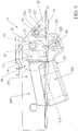
- the first portion 100 of the quick fastening means 9 rotates about the rotation axis R passing from a disengagement position which permits the disengagement of the arm 200 ( Figures 5, 6 ) to an engagement position which does not permit the disengagement of the arm 200 ( Figure 9 ).
- the U-shaped cross section of the rotating portion 21 faces upwards, namely the transversal sheet 29 of the rotating portion 21 faces downwards and permits the insertion from the top of the hook slot 17 of the extension 15 of the arm 200 which is positioned above the outer surface of the engaging pivot 41 until the hook slot 17 completely rests on top of the outer surface of the engaging pivot 41.
- the insertion from the top of the hook slot 17 is guided within the outer sheet 25 and the inner sheet 27 of the rotating portion 21.
- the U-shaped cross section of the rotating portion 21 faces downwards, namely the transversal sheet 29 of the rotating portion 21 faces upwards and does not permit the disengagement of the hook slot 17 of the extension 15 of the arm 200.
- the engaging pivot 41 rotates in turn about the rotation axis R.
- the inner surface of the hook slot 17 of the arm 200 is in sliding contact with the outer surface of the engaging pivot 41 during the rotation of the first portion 100 of the quick fastening means 9 about the rotation axis R.
- the hook slot 17 has the opening 170 of the U always facing downwards during the passage from the disengagement position to the engagement position of the first portion 100 of the quick fastening means 9.
- the transversal sheet 29 of the rotating portion 21 of the first portion 100 of the quick fastening means 9 extends in the direction of the longitudinal axis L with the extension 115 of the first portion 100 of the quick fastening means 9.
- the extension 115 is directed towards the back of the lawnmower 1 when the first portion 100 of the quick fastening means 9 is in the engagement position.
- the rotating portion 21 comprises a transversal hinge through hole 129 adapted to rotatably mount the lever 125.
- the transversal sheet 29 of the rotating portion 21 mounts a hinge cylinder 129 of the rotating portion 21 which comprises a transversal hinge through hole 120.
- the lever 125 of the first portion 100 of the quick fastening means 9 comprises two hinge places 195 which overlap the transversal hinge through hole 120 and permit a hinge pivot 20 of the rotating portion 21 to pass through the two hinge places 195 of the lever 125 and the transversal hinge through hole 120 of the rotating portion21, thus pivoting the lever 125 with the rotating portion 21.
- the lever 125 is a sheet comprising an elongated portion 126 which overlaps, at least for one portion, the extension 115 of the rotating portion 21.
- the lever 125 rotates on the hinge pivot 20 of the rotating portion 21 and is constrained in the rotational movement by the elongated portion 126 adapted to enter in contact with the extension 115 of the rotating portion 21.
- the transversal sheet 29 extends in a first extension 121 outwards in a direction parallel to the rotation axis R, as shown in particular in Figures 2 and 3 .
- Said first extension 121 is adapted to be pressed by a user who wants to rotate the rotating portion 21.
- the first extension 121 also serves the function as stroke-end stop for the rotating portion 21, as seen in Figures 2 and 11 , in which the first extension 121 abuts against an upper surface of the arm 200.
- the lower bracket 402 extends in a second extension 122 outwards in a direction parallel to the rotation axis R, as shown in particular in Figures 2 and 3 .
- Said second extension 122 serves the function to constrain the clockwise rotation of the rotating portion 21 about the rotation axis R, when the first portion 100 is at the disengagement position, as shown in Figures 5 and 6 .
- the second extension 122 of the lower bracket 402 of the first portion 100 abuts against a lower surface of the arm 200.
- said first extension 121 and second extension 122 are pressed by a foot of the user without having to lean and without having to use the hands.
- the outer sheet 25 and the inner sheet 26 of the rotating portion 21 comprise a constraint slit 255 which is shaped as a circumference arc.
- the outer sheet 25 comprises an outer constraint slit 255 corresponding on the other side to an inner constraint slit 255 which is obtained in the inner sheet 27 of the rotating portion.
- the lever 125 comprises two constraint places 155 which overlap the constraint slits 255 of the rotating portion 21 and permit the constraint pivot 95 to pass through and pivot the rotating portion 21 with the lever 125, thus constraining the movement of the lever 125 within the circumference arc identified by the constraint slit 255 of the rotating portion 21.
- the lever 125 rotates about the hinge pivot 20 of the rotating portion 21 from an abutment position of the elongated portion 126 of the lever 125 against the extension 115 of the rotating portion 21 which coincides with a first stop position of the constraint pivot 95 at one extremity 256 of the two extremities of the constraint slit 255, to a second stop position of the constraint pivot 95 at the other extremity 257 of the constraint slit 255.
- the constraint pivot 95 is adapted to enter the locking notch 19 of the arm 200 when the constraint pivot 95 is at a first position inside the constraint slit 255, said recall spring 450 keeps the first position of the constraint pivot 95 in place.
- the second portion 200 namely the arm 200 of the fastening means 9 comprises the locking notch 19 which is placed in an opposing direction with respect to the extension 15 comprising the hook slot 17.
- Said locking notch 19 of the arm 200 of the fastening means 9 comprises a lead-in portion 45, a shoulder portion 49 and a further recessed portion 53 which follows the shoulder portion 49, in which said further recessed portion 53 is obtained in the direction of the extension 15 comprising the hook-shaped slot 17.
- the portion 100 When the first portion 100 of the quick fastening means 9 is in the disengagement position and is constrained to the clockwise rotation by the abutment of the arm 200 against the second extension 122, the portion 100 may be rotated by pressing the first extension 121 of the transversal sheet 29 of the first portion 100 until the constraint pivot 95 passes from the second stop position ( Figure 11 ) to the first stop position ( Figure 9 ) so that the constraint pivot 95 penetrates the locking notch 19 to be positioned inside the further recessed portion 53 of the locking notch 19, thus fastening the arm 200 with the first portion 100 of the quick fastening means 9 and thus fastening the front portion 5 of the lawnmower 1 with the frontal implement 3 in an advantageously safe and stable manner.
- the first stop position of the constraint pivot 95 is kept stable by means of the recall spring 450 ( Figures 9 and 10 ).
- the lower bracket 402 of the rotating portion 21 integrally mounts a first extremity 451 of the recall spring 450.
- a second extremity 452 of the recall spring 450 is integrally mounted with the lever 125.
- the second extremity 452 of the recall spring 450 is engaged with the lever 125 by means of the constraint pivot 95 in turn arranged at the constraint place 155.
- the constraint place 155 is opposite to the elongated portion 126 of the lever 125 with respect to the hinge pivot 20.
- the constraint pivot 95 passes from the first stop position ( Figure 9 ) to the second stop position ( Figure 11 ) leaving the locking notch 19 of the arm 200 and permitting the first portion 100 of the quick fastening means 9 to rotate about the rotation axis R to the constraint given by the abutment of the arm 200 against the second extension 122, advantageously permitting the first portion 100 of the quick fastening means 9 to pass from the engagement position to the disengagement position and disengage the arm 200 from the first portion 100 of the quick fastening means 9.
- the first portion 100 of the quick fastening means 9 rotates about the rotation axis R to an engagement position in which the transversal sheet 29 of the rotating portion locks the escaping of the hook slot 17 of the extension 15 of the arm 200 out of the engaging pivot 41 of the rotating portion 21 of the first portion 100 of the quick fastening means 9.
- the constraint pivot 95 passes to the first stop position inside the constraint slit 255 which coincides with the position of the constraint pivot 95 inside the further recessed portion 53 in the locking notch 19 of the arm 200.
- the recall spring 450 passes from a resting position, in which the elongated portion 126 of the lever 125 is raised from the extension 115 of the rotating portion 21 and the constraint pivot 95 is at the first stop position inside the constraint slit 255 of the rotating portion 21, to an elongated position of the recall spring 450, in which the elongated portion 126 of the lever 125 abuts against the extension 115 of the rotating portion 21 for then returning to a resting position in which the elongated portion 126 of the lever 125 is raised from the extension 115 of the rotating portion 21 and the constraint pivot 95 is in the second stop position inside of the constraint slit 255 of the rotating portion 21.
- the constraint pivot 95 is taken out of the locking notch 19 of the arm 200 thus permitting the first portion 100 of the quick fastening means 9 to rotate about the rotation axis R and pass from the engagement position to the disengagement position of the first portion 100 of the quick fastening means 9 and permit the arm 200 to be disengaged from the first portion 100 of the quick fastening means 9 and permit the disengagement of the frontal implement 3 from the front portion 5 of the lawnmower 1.
- said rotation axis R is different from the axis of the front wheel of the lawnmower 1, but said rotation axis R is placed along a direction parallel to the axis of the front wheel of the lawnmower 1.
- the rotating portion 21 is provided to only comprise the lower bracket 402 which welds the hub 69. Said lower bracket 402 is necessary and advantageous to connect an extremity of the recall spring 450.
- a further alternative includes the rotating portion 21 comprising only one constraint slit 255 which is shaped as a circumference arc, and the constraint pivot 95 of the first portion 100 engaging the lever 125 with the constraint slit 255 of the rotating portion 21 constraining the movement of the lever 125 adapted to rotate about the hinge pivot 20.
- the manufacture of the lawnmower 1 comprising the fastening means 9 between a front portion 5 of the lawnmower 1 and the frontal implement 3 of the lawnmower 1 allows a quick connection between lawnmower 1 and frontal implement 3, which is not wedged.
- the fastening means 9 of the lawnmower advantageously also permit a safe connection in view of vibrations and jamming or ground resistances.
- the quick fastening means 9 are smaller and compact in size and easier to be handled.
Landscapes
- Life Sciences & Earth Sciences (AREA)
- Environmental Sciences (AREA)
- Zoology (AREA)
- Engineering & Computer Science (AREA)
- Mechanical Engineering (AREA)
- Soil Sciences (AREA)
- Soil Working Implements (AREA)
- Transplanting Machines (AREA)
Applications Claiming Priority (1)
| Application Number | Priority Date | Filing Date | Title |
|---|---|---|---|
| ITUA2016A001422A ITUA20161422A1 (it) | 2016-03-07 | 2016-03-07 | Tosaerba con aggancio rapido per accessori frontali. |
Publications (2)
| Publication Number | Publication Date |
|---|---|
| EP3216338A1 true EP3216338A1 (fr) | 2017-09-13 |
| EP3216338B1 EP3216338B1 (fr) | 2018-12-05 |
Family
ID=56203547
Family Applications (1)
| Application Number | Title | Priority Date | Filing Date |
|---|---|---|---|
| EP17159116.7A Active EP3216338B1 (fr) | 2016-03-07 | 2017-03-03 | Tondeuse avec fixation rapide pour outils frontaux |
Country Status (2)
| Country | Link |
|---|---|
| EP (1) | EP3216338B1 (fr) |
| IT (1) | ITUA20161422A1 (fr) |
Cited By (1)
| Publication number | Priority date | Publication date | Assignee | Title |
|---|---|---|---|---|
| EP3682722A1 (fr) * | 2019-01-18 | 2020-07-22 | AGCO International GmbH | Outil amélioré pour le foin |
Citations (6)
| Publication number | Priority date | Publication date | Assignee | Title |
|---|---|---|---|---|
| US3958399A (en) * | 1975-02-18 | 1976-05-25 | Sperry Rand Corporation | Header attachment structure |
| US4280317A (en) * | 1980-04-16 | 1981-07-28 | Sperry Corporation | Adjustable coupling apparatus |
| WO2007136313A1 (fr) | 2006-05-18 | 2007-11-29 | Ggp Sweden Ab | Support d'instrument |
| US7302765B1 (en) | 2004-09-20 | 2007-12-04 | Quick Attach Attachments, Inc. | Implement attaching apparatus |
| US20100170212A1 (en) | 2007-01-12 | 2010-07-08 | Johansson Joergen | Adjustable drive axle for a lawn mower |
| EP2676534A1 (fr) * | 2012-06-18 | 2013-12-25 | GGP Sweden AB | Supports de fixation |
-
2016
- 2016-03-07 IT ITUA2016A001422A patent/ITUA20161422A1/it unknown
-
2017
- 2017-03-03 EP EP17159116.7A patent/EP3216338B1/fr active Active
Patent Citations (7)
| Publication number | Priority date | Publication date | Assignee | Title |
|---|---|---|---|---|
| US3958399A (en) * | 1975-02-18 | 1976-05-25 | Sperry Rand Corporation | Header attachment structure |
| US4280317A (en) * | 1980-04-16 | 1981-07-28 | Sperry Corporation | Adjustable coupling apparatus |
| US7302765B1 (en) | 2004-09-20 | 2007-12-04 | Quick Attach Attachments, Inc. | Implement attaching apparatus |
| WO2007136313A1 (fr) | 2006-05-18 | 2007-11-29 | Ggp Sweden Ab | Support d'instrument |
| US20100170212A1 (en) | 2007-01-12 | 2010-07-08 | Johansson Joergen | Adjustable drive axle for a lawn mower |
| EP2676534A1 (fr) * | 2012-06-18 | 2013-12-25 | GGP Sweden AB | Supports de fixation |
| EP2676534B1 (fr) | 2012-06-18 | 2015-04-08 | GGP Sweden AB | Supports de fixation |
Cited By (2)
| Publication number | Priority date | Publication date | Assignee | Title |
|---|---|---|---|---|
| EP3682722A1 (fr) * | 2019-01-18 | 2020-07-22 | AGCO International GmbH | Outil amélioré pour le foin |
| US11357168B2 (en) | 2019-01-18 | 2022-06-14 | Agco Feucht Gmbh | Towed implement that compensates for unbalanced loads caused by offset centre of gravity |
Also Published As
| Publication number | Publication date |
|---|---|
| EP3216338B1 (fr) | 2018-12-05 |
| ITUA20161422A1 (it) | 2017-09-07 |
Similar Documents
| Publication | Publication Date | Title |
|---|---|---|
| JP5668142B2 (ja) | 車両シート用縦方向調整装置 | |
| EP1787777B1 (fr) | Capot de protection modulaire pour scie motorisée | |
| EP1465507B1 (fr) | Boucle de fixation a auto-verrouillage et a reglage d une sa ngle | |
| US5636504A (en) | Handle assembly for outdoor power equipment | |
| US7275753B1 (en) | Towing dolly cradle assembly | |
| TWI540033B (zh) | 動力鋸的防護系統 | |
| US9073460B2 (en) | Road finisher and seat console | |
| EP0021885B1 (fr) | Manette de commande pour vanne | |
| EP3216338B1 (fr) | Tondeuse avec fixation rapide pour outils frontaux | |
| EP2374585B1 (fr) | Dispositif de réglage de l'angle de biseau pour scie circulaire | |
| WO2015044141A1 (fr) | Attache par serrage de sécurité | |
| EP2676534B1 (fr) | Supports de fixation | |
| US9186810B1 (en) | Bracket assembly and retaining device for collapsible stand | |
| WO2013150236A1 (fr) | Poignee amovible cooperant avec une anse | |
| US6910275B2 (en) | Cable-stripping tool | |
| FR2724689A1 (fr) | Mecanisme de verrouillage destine a equiper principalement une machine agricole | |
| EP2626178B1 (fr) | Machine à découper | |
| EP1728710B1 (fr) | Sellette d'attelage | |
| FR2584913A1 (fr) | Poignee de casserole demontable | |
| US20090223191A1 (en) | Mechanical Interlock for a Control Member | |
| US2213434A (en) | Supporting bracket | |
| EP3099155B1 (fr) | Guidon de tondeuse à gazon réglable en hauteur | |
| US4869053A (en) | Quick release safety attachment for a stirrup | |
| US5058366A (en) | Safety release attachment for stirrup | |
| WO2017168102A1 (fr) | Structure d'assise reglable d'un siege de vehicule comportant un brin boucle de ceinture de securite. |
Legal Events
| Date | Code | Title | Description |
|---|---|---|---|
| PUAI | Public reference made under article 153(3) epc to a published international application that has entered the european phase |
Free format text: ORIGINAL CODE: 0009012 |
|
| STAA | Information on the status of an ep patent application or granted ep patent |
Free format text: STATUS: THE APPLICATION HAS BEEN PUBLISHED |
|
| AK | Designated contracting states |
Kind code of ref document: A1 Designated state(s): AL AT BE BG CH CY CZ DE DK EE ES FI FR GB GR HR HU IE IS IT LI LT LU LV MC MK MT NL NO PL PT RO RS SE SI SK SM TR |
|
| AX | Request for extension of the european patent |
Extension state: BA ME |
|
| RAP1 | Party data changed (applicant data changed or rights of an application transferred) |
Owner name: STIGA S.P.A. IN BREVE ANCHE ST. S.P.A. |
|
| STAA | Information on the status of an ep patent application or granted ep patent |
Free format text: STATUS: REQUEST FOR EXAMINATION WAS MADE |
|
| 17P | Request for examination filed |
Effective date: 20180312 |
|
| RBV | Designated contracting states (corrected) |
Designated state(s): AL AT BE BG CH CY CZ DE DK EE ES FI FR GB GR HR HU IE IS IT LI LT LU LV MC MK MT NL NO PL PT RO RS SE SI SK SM TR |
|
| GRAP | Despatch of communication of intention to grant a patent |
Free format text: ORIGINAL CODE: EPIDOSNIGR1 |
|
| STAA | Information on the status of an ep patent application or granted ep patent |
Free format text: STATUS: GRANT OF PATENT IS INTENDED |
|
| RIC1 | Information provided on ipc code assigned before grant |
Ipc: A01D 43/10 20060101AFI20180528BHEP Ipc: A01B 59/06 20060101ALI20180528BHEP |
|
| INTG | Intention to grant announced |
Effective date: 20180621 |
|
| GRAS | Grant fee paid |
Free format text: ORIGINAL CODE: EPIDOSNIGR3 |
|
| GRAA | (expected) grant |
Free format text: ORIGINAL CODE: 0009210 |
|
| STAA | Information on the status of an ep patent application or granted ep patent |
Free format text: STATUS: THE PATENT HAS BEEN GRANTED |
|
| AK | Designated contracting states |
Kind code of ref document: B1 Designated state(s): AL AT BE BG CH CY CZ DE DK EE ES FI FR GB GR HR HU IE IS IT LI LT LU LV MC MK MT NL NO PL PT RO RS SE SI SK SM TR |
|
| REG | Reference to a national code |
Ref country code: GB Ref legal event code: FG4D |
|
| REG | Reference to a national code |
Ref country code: CH Ref legal event code: EP |
|
| REG | Reference to a national code |
Ref country code: AT Ref legal event code: REF Ref document number: 1071864 Country of ref document: AT Kind code of ref document: T Effective date: 20181215 |
|
| REG | Reference to a national code |
Ref country code: IE Ref legal event code: FG4D |
|
| REG | Reference to a national code |
Ref country code: DE Ref legal event code: R096 Ref document number: 602017001137 Country of ref document: DE |
|
| REG | Reference to a national code |
Ref country code: SE Ref legal event code: TRGR |
|
| REG | Reference to a national code |
Ref country code: NL Ref legal event code: MP Effective date: 20181205 |
|
| REG | Reference to a national code |
Ref country code: AT Ref legal event code: MK05 Ref document number: 1071864 Country of ref document: AT Kind code of ref document: T Effective date: 20181205 |
|
| REG | Reference to a national code |
Ref country code: LT Ref legal event code: MG4D |
|
| PG25 | Lapsed in a contracting state [announced via postgrant information from national office to epo] |
Ref country code: ES Free format text: LAPSE BECAUSE OF FAILURE TO SUBMIT A TRANSLATION OF THE DESCRIPTION OR TO PAY THE FEE WITHIN THE PRESCRIBED TIME-LIMIT Effective date: 20181205 Ref country code: LV Free format text: LAPSE BECAUSE OF FAILURE TO SUBMIT A TRANSLATION OF THE DESCRIPTION OR TO PAY THE FEE WITHIN THE PRESCRIBED TIME-LIMIT Effective date: 20181205 Ref country code: HR Free format text: LAPSE BECAUSE OF FAILURE TO SUBMIT A TRANSLATION OF THE DESCRIPTION OR TO PAY THE FEE WITHIN THE PRESCRIBED TIME-LIMIT Effective date: 20181205 Ref country code: LT Free format text: LAPSE BECAUSE OF FAILURE TO SUBMIT A TRANSLATION OF THE DESCRIPTION OR TO PAY THE FEE WITHIN THE PRESCRIBED TIME-LIMIT Effective date: 20181205 Ref country code: BG Free format text: LAPSE BECAUSE OF FAILURE TO SUBMIT A TRANSLATION OF THE DESCRIPTION OR TO PAY THE FEE WITHIN THE PRESCRIBED TIME-LIMIT Effective date: 20190305 Ref country code: FI Free format text: LAPSE BECAUSE OF FAILURE TO SUBMIT A TRANSLATION OF THE DESCRIPTION OR TO PAY THE FEE WITHIN THE PRESCRIBED TIME-LIMIT Effective date: 20181205 Ref country code: NO Free format text: LAPSE BECAUSE OF FAILURE TO SUBMIT A TRANSLATION OF THE DESCRIPTION OR TO PAY THE FEE WITHIN THE PRESCRIBED TIME-LIMIT Effective date: 20190305 Ref country code: AT Free format text: LAPSE BECAUSE OF FAILURE TO SUBMIT A TRANSLATION OF THE DESCRIPTION OR TO PAY THE FEE WITHIN THE PRESCRIBED TIME-LIMIT Effective date: 20181205 |
|
| PG25 | Lapsed in a contracting state [announced via postgrant information from national office to epo] |
Ref country code: GR Free format text: LAPSE BECAUSE OF FAILURE TO SUBMIT A TRANSLATION OF THE DESCRIPTION OR TO PAY THE FEE WITHIN THE PRESCRIBED TIME-LIMIT Effective date: 20190306 Ref country code: AL Free format text: LAPSE BECAUSE OF FAILURE TO SUBMIT A TRANSLATION OF THE DESCRIPTION OR TO PAY THE FEE WITHIN THE PRESCRIBED TIME-LIMIT Effective date: 20181205 Ref country code: RS Free format text: LAPSE BECAUSE OF FAILURE TO SUBMIT A TRANSLATION OF THE DESCRIPTION OR TO PAY THE FEE WITHIN THE PRESCRIBED TIME-LIMIT Effective date: 20181205 |
|
| PG25 | Lapsed in a contracting state [announced via postgrant information from national office to epo] |
Ref country code: NL Free format text: LAPSE BECAUSE OF FAILURE TO SUBMIT A TRANSLATION OF THE DESCRIPTION OR TO PAY THE FEE WITHIN THE PRESCRIBED TIME-LIMIT Effective date: 20181205 |
|
| PG25 | Lapsed in a contracting state [announced via postgrant information from national office to epo] |
Ref country code: PT Free format text: LAPSE BECAUSE OF FAILURE TO SUBMIT A TRANSLATION OF THE DESCRIPTION OR TO PAY THE FEE WITHIN THE PRESCRIBED TIME-LIMIT Effective date: 20190405 Ref country code: PL Free format text: LAPSE BECAUSE OF FAILURE TO SUBMIT A TRANSLATION OF THE DESCRIPTION OR TO PAY THE FEE WITHIN THE PRESCRIBED TIME-LIMIT Effective date: 20181205 Ref country code: CZ Free format text: LAPSE BECAUSE OF FAILURE TO SUBMIT A TRANSLATION OF THE DESCRIPTION OR TO PAY THE FEE WITHIN THE PRESCRIBED TIME-LIMIT Effective date: 20181205 |
|
| PG25 | Lapsed in a contracting state [announced via postgrant information from national office to epo] |
Ref country code: SK Free format text: LAPSE BECAUSE OF FAILURE TO SUBMIT A TRANSLATION OF THE DESCRIPTION OR TO PAY THE FEE WITHIN THE PRESCRIBED TIME-LIMIT Effective date: 20181205 Ref country code: RO Free format text: LAPSE BECAUSE OF FAILURE TO SUBMIT A TRANSLATION OF THE DESCRIPTION OR TO PAY THE FEE WITHIN THE PRESCRIBED TIME-LIMIT Effective date: 20181205 Ref country code: IS Free format text: LAPSE BECAUSE OF FAILURE TO SUBMIT A TRANSLATION OF THE DESCRIPTION OR TO PAY THE FEE WITHIN THE PRESCRIBED TIME-LIMIT Effective date: 20190405 Ref country code: EE Free format text: LAPSE BECAUSE OF FAILURE TO SUBMIT A TRANSLATION OF THE DESCRIPTION OR TO PAY THE FEE WITHIN THE PRESCRIBED TIME-LIMIT Effective date: 20181205 Ref country code: SM Free format text: LAPSE BECAUSE OF FAILURE TO SUBMIT A TRANSLATION OF THE DESCRIPTION OR TO PAY THE FEE WITHIN THE PRESCRIBED TIME-LIMIT Effective date: 20181205 |
|
| REG | Reference to a national code |
Ref country code: DE Ref legal event code: R097 Ref document number: 602017001137 Country of ref document: DE |
|
| PLBE | No opposition filed within time limit |
Free format text: ORIGINAL CODE: 0009261 |
|
| STAA | Information on the status of an ep patent application or granted ep patent |
Free format text: STATUS: NO OPPOSITION FILED WITHIN TIME LIMIT |
|
| PG25 | Lapsed in a contracting state [announced via postgrant information from national office to epo] |
Ref country code: SI Free format text: LAPSE BECAUSE OF FAILURE TO SUBMIT A TRANSLATION OF THE DESCRIPTION OR TO PAY THE FEE WITHIN THE PRESCRIBED TIME-LIMIT Effective date: 20181205 Ref country code: DK Free format text: LAPSE BECAUSE OF FAILURE TO SUBMIT A TRANSLATION OF THE DESCRIPTION OR TO PAY THE FEE WITHIN THE PRESCRIBED TIME-LIMIT Effective date: 20181205 Ref country code: MC Free format text: LAPSE BECAUSE OF FAILURE TO SUBMIT A TRANSLATION OF THE DESCRIPTION OR TO PAY THE FEE WITHIN THE PRESCRIBED TIME-LIMIT Effective date: 20181205 |
|
| 26N | No opposition filed |
Effective date: 20190906 |
|
| PG25 | Lapsed in a contracting state [announced via postgrant information from national office to epo] |
Ref country code: LU Free format text: LAPSE BECAUSE OF NON-PAYMENT OF DUE FEES Effective date: 20190303 |
|
| REG | Reference to a national code |
Ref country code: BE Ref legal event code: MM Effective date: 20190331 |
|
| PG25 | Lapsed in a contracting state [announced via postgrant information from national office to epo] |
Ref country code: IE Free format text: LAPSE BECAUSE OF NON-PAYMENT OF DUE FEES Effective date: 20190303 |
|
| PG25 | Lapsed in a contracting state [announced via postgrant information from national office to epo] |
Ref country code: BE Free format text: LAPSE BECAUSE OF NON-PAYMENT OF DUE FEES Effective date: 20190331 |
|
| PG25 | Lapsed in a contracting state [announced via postgrant information from national office to epo] |
Ref country code: TR Free format text: LAPSE BECAUSE OF FAILURE TO SUBMIT A TRANSLATION OF THE DESCRIPTION OR TO PAY THE FEE WITHIN THE PRESCRIBED TIME-LIMIT Effective date: 20181205 |
|
| PG25 | Lapsed in a contracting state [announced via postgrant information from national office to epo] |
Ref country code: MT Free format text: LAPSE BECAUSE OF NON-PAYMENT OF DUE FEES Effective date: 20190303 |
|
| REG | Reference to a national code |
Ref country code: CH Ref legal event code: PL |
|
| PG25 | Lapsed in a contracting state [announced via postgrant information from national office to epo] |
Ref country code: CH Free format text: LAPSE BECAUSE OF NON-PAYMENT OF DUE FEES Effective date: 20200331 Ref country code: LI Free format text: LAPSE BECAUSE OF NON-PAYMENT OF DUE FEES Effective date: 20200331 |
|
| PG25 | Lapsed in a contracting state [announced via postgrant information from national office to epo] |
Ref country code: CY Free format text: LAPSE BECAUSE OF FAILURE TO SUBMIT A TRANSLATION OF THE DESCRIPTION OR TO PAY THE FEE WITHIN THE PRESCRIBED TIME-LIMIT Effective date: 20181205 |
|
| PG25 | Lapsed in a contracting state [announced via postgrant information from national office to epo] |
Ref country code: HU Free format text: LAPSE BECAUSE OF FAILURE TO SUBMIT A TRANSLATION OF THE DESCRIPTION OR TO PAY THE FEE WITHIN THE PRESCRIBED TIME-LIMIT; INVALID AB INITIO Effective date: 20170303 |
|
| PG25 | Lapsed in a contracting state [announced via postgrant information from national office to epo] |
Ref country code: MK Free format text: LAPSE BECAUSE OF FAILURE TO SUBMIT A TRANSLATION OF THE DESCRIPTION OR TO PAY THE FEE WITHIN THE PRESCRIBED TIME-LIMIT Effective date: 20181205 |
|
| P01 | Opt-out of the competence of the unified patent court (upc) registered |
Effective date: 20230421 |
|
| PGFP | Annual fee paid to national office [announced via postgrant information from national office to epo] |
Ref country code: DE Payment date: 20250521 Year of fee payment: 9 |
|
| PGFP | Annual fee paid to national office [announced via postgrant information from national office to epo] |
Ref country code: SE Payment date: 20260327 Year of fee payment: 10 |
|
| PGFP | Annual fee paid to national office [announced via postgrant information from national office to epo] |
Ref country code: GB Payment date: 20260302 Year of fee payment: 10 |
|
| PGFP | Annual fee paid to national office [announced via postgrant information from national office to epo] |
Ref country code: IT Payment date: 20260303 Year of fee payment: 10 |
|
| PGFP | Annual fee paid to national office [announced via postgrant information from national office to epo] |
Ref country code: FR Payment date: 20260330 Year of fee payment: 10 |