EP3216352A1 - Kühlvorrichtung und verfahren zum kühlen von rieselfähigen elementen - Google Patents
Kühlvorrichtung und verfahren zum kühlen von rieselfähigen elementen Download PDFInfo
- Publication number
- EP3216352A1 EP3216352A1 EP16159983.2A EP16159983A EP3216352A1 EP 3216352 A1 EP3216352 A1 EP 3216352A1 EP 16159983 A EP16159983 A EP 16159983A EP 3216352 A1 EP3216352 A1 EP 3216352A1
- Authority
- EP
- European Patent Office
- Prior art keywords
- cooling
- refrigerant
- circumferential wall
- rotary tumbler
- cooling device
- Prior art date
- Legal status (The legal status is an assumption and is not a legal conclusion. Google has not performed a legal analysis and makes no representation as to the accuracy of the status listed.)
- Granted
Links
Images


Classifications
-
- F—MECHANICAL ENGINEERING; LIGHTING; HEATING; WEAPONS; BLASTING
- F25—REFRIGERATION OR COOLING; COMBINED HEATING AND REFRIGERATION SYSTEMS; HEAT PUMP SYSTEMS; MANUFACTURE OR STORAGE OF ICE; LIQUEFACTION SOLIDIFICATION OF GASES
- F25D—REFRIGERATORS; COLD ROOMS; ICE-BOXES; COOLING OR FREEZING APPARATUS NOT OTHERWISE PROVIDED FOR
- F25D13/00—Stationary devices, e.g. cold-rooms
- F25D13/06—Stationary devices, e.g. cold-rooms with conveyors carrying articles to be cooled through the cooling space
- F25D13/067—Stationary devices, e.g. cold-rooms with conveyors carrying articles to be cooled through the cooling space with circulation of gaseous cooling fluid
-
- A—HUMAN NECESSITIES
- A23—FOODS OR FOODSTUFFS; TREATMENT THEREOF, NOT COVERED BY OTHER CLASSES
- A23B—PRESERVATION OF FOODS, FOODSTUFFS OR NON-ALCOHOLIC BEVERAGES; CHEMICAL RIPENING OF FRUIT OR VEGETABLES
- A23B2/00—Preservation of foods or foodstuffs, in general
- A23B2/80—Freezing; Subsequent thawing; Cooling
- A23B2/803—Materials being transported through or in the apparatus, with or without shaping, e.g. in the form of powders, granules or flakes
-
- A—HUMAN NECESSITIES
- A23—FOODS OR FOODSTUFFS; TREATMENT THEREOF, NOT COVERED BY OTHER CLASSES
- A23B—PRESERVATION OF FOODS, FOODSTUFFS OR NON-ALCOHOLIC BEVERAGES; CHEMICAL RIPENING OF FRUIT OR VEGETABLES
- A23B2/00—Preservation of foods or foodstuffs, in general
- A23B2/80—Freezing; Subsequent thawing; Cooling
- A23B2/803—Materials being transported through or in the apparatus, with or without shaping, e.g. in the form of powders, granules or flakes
- A23B2/8033—Materials being transported through or in the apparatus, with or without shaping, e.g. in the form of powders, granules or flakes with packages or with shaping in the form of blocks or portions
-
- A—HUMAN NECESSITIES
- A23—FOODS OR FOODSTUFFS; TREATMENT THEREOF, NOT COVERED BY OTHER CLASSES
- A23B—PRESERVATION OF FOODS, FOODSTUFFS OR NON-ALCOHOLIC BEVERAGES; CHEMICAL RIPENING OF FRUIT OR VEGETABLES
- A23B2/00—Preservation of foods or foodstuffs, in general
- A23B2/80—Freezing; Subsequent thawing; Cooling
- A23B2/85—Freezing; Subsequent thawing; Cooling with addition of or treatment with chemicals
- A23B2/88—Freezing; Subsequent thawing; Cooling with addition of or treatment with chemicals with direct contact between the food and the chemical, e.g. liquid N2 at cryogenic temperature
-
- A—HUMAN NECESSITIES
- A23—FOODS OR FOODSTUFFS; TREATMENT THEREOF, NOT COVERED BY OTHER CLASSES
- A23B—PRESERVATION OF FOODS, FOODSTUFFS OR NON-ALCOHOLIC BEVERAGES; CHEMICAL RIPENING OF FRUIT OR VEGETABLES
- A23B4/00—Preservation of meat, sausages, fish or fish products
- A23B4/06—Freezing; Subsequent thawing; Cooling
- A23B4/062—Freezing; Subsequent thawing; Cooling the materials being transported through or in the apparatus with or without shaping, e.g. in the form of powder, granules or flakes
-
- A—HUMAN NECESSITIES
- A23—FOODS OR FOODSTUFFS; TREATMENT THEREOF, NOT COVERED BY OTHER CLASSES
- A23B—PRESERVATION OF FOODS, FOODSTUFFS OR NON-ALCOHOLIC BEVERAGES; CHEMICAL RIPENING OF FRUIT OR VEGETABLES
- A23B4/00—Preservation of meat, sausages, fish or fish products
- A23B4/06—Freezing; Subsequent thawing; Cooling
- A23B4/062—Freezing; Subsequent thawing; Cooling the materials being transported through or in the apparatus with or without shaping, e.g. in the form of powder, granules or flakes
- A23B4/064—Freezing; Subsequent thawing; Cooling the materials being transported through or in the apparatus with or without shaping, e.g. in the form of powder, granules or flakes with packages or with shaping in the form of blocks or portions
-
- A—HUMAN NECESSITIES
- A23—FOODS OR FOODSTUFFS; TREATMENT THEREOF, NOT COVERED BY OTHER CLASSES
- A23B—PRESERVATION OF FOODS, FOODSTUFFS OR NON-ALCOHOLIC BEVERAGES; CHEMICAL RIPENING OF FRUIT OR VEGETABLES
- A23B4/00—Preservation of meat, sausages, fish or fish products
- A23B4/06—Freezing; Subsequent thawing; Cooling
- A23B4/08—Freezing; Subsequent thawing; Cooling with addition of chemicals or treatment with chemicals before or during cooling, e.g. in the form of an ice coating or frozen block
-
- F—MECHANICAL ENGINEERING; LIGHTING; HEATING; WEAPONS; BLASTING
- F25—REFRIGERATION OR COOLING; COMBINED HEATING AND REFRIGERATION SYSTEMS; HEAT PUMP SYSTEMS; MANUFACTURE OR STORAGE OF ICE; LIQUEFACTION SOLIDIFICATION OF GASES
- F25D—REFRIGERATORS; COLD ROOMS; ICE-BOXES; COOLING OR FREEZING APPARATUS NOT OTHERWISE PROVIDED FOR
- F25D2500/00—Problems to be solved
- F25D2500/02—Geometry problems
Definitions
- the present invention is directed to a cooling device and a method for cooling pourable items, in particular food items, on an industrial scale inside a rotary tumbler.
- a cooling effect can be obtained, e. g., with a refrigerant such as nitrogen or carbon dioxide.
- the refrigerant can be introduced into the tumbler either directly or, alternatively, through a perforated tumbler wall. In the latter case the refrigerant can evaporate or sublimate outside the tumbler. Fans can cause it to penetrate through the perforated wall into the tumbler.
- the motion of the items through the tumbler along its axis can be achieved, e.g., with an auger inside the tumbler.
- the tumbler can be tilted. In that case, gravity can cause the items to move through the tumbler.
- a pre-spray bar for spraying a refrigerant into the rotary tumbler can be added, for example, near the food inlet. Such a pre-spray bar may lead to an increased cooling rate in a locally restricted part of the tumbler.
- the speed of each fan can be tuned individually. Thereby, the amount of the refrigerant entering the tumbler can be varied locally.
- these possibilities of adjusting the refrigerant flow into the rotary tumbler are not sufficient for all applications. In particular, those pourable items that require a cooling in two steps at two different cooling rates may require enhanced spatial adjustment of the cooling rates.
- the rotary tumbler is divided into
- the cooling device is preferably an installation for industrial mass production of food products. Any food products comprising pourable items may be chilled, cooled or frozen using the cooling device. In particular, this is advantageous for heat-sensitive or perishable products.
- Pourable items are objects with a solid bulk, a multitude of which can be processed simultaneously. Examples can be noodles, meat balls, fries or vegetables. Also, these pourable items may be coated, for example, by a sauce.
- the rotary tumbler is not only arranged for cooling, but also for coating the pourable items. A multitude of the pourable items forms a food product, e.g. a bag of noodles. Cooling the pourable items is preferably performed by moving them through the rotary tumbler.
- the rotary tumbler preferably has a rotationally symmetric shape, in particular a cylindrical shape.
- a first side which is a first front side of the cylinder
- the pourable items can be introduced into the rotary tumbler through the inlet.
- a second front side of the rotary tumbler the pourable items can be extracted from the rotary tumbler through the outlet.
- the axis is a cylinder axis as defined in a mathematical sense. In a preferred orientation of the rotary tumbler, the axis is oriented horizontally.
- Pourable items that are moved through the rotary tumbler along its axis can be cooled by a refrigerant.
- the refrigerant is preferably nitrogen and/or carbon dioxide.
- the rotary tumbler is preferably made of a metal, in particular stainless steel.
- liquid nitrogen has a temperature of 77 K [Kelvin] and liquid carbon dioxide of 194 K.
- the refrigerant is preferably provided in a liquid form. It can either evaporate outside the rotary tumbler and enter the rotary tumbler through the perforation openings of the circumferential wall, or it can be injected into the rotary tumbler directly and evaporate within the rotary tumbler.
- the perforation openings are adapted to the size, the weight and/or other properties of the pourable items.
- the perforation openings are preferably arranged uniformly, i.e. with constant spacings in between adjacent perforation openings.
- the perforation openings preferably have, e.g., a circular, an elliptical or an L-shape. It is preferred that a multitude of the perforation openings has the same shape, in particular that all perforation openings of the first cooling zone have the same shape and that all of the perforation openings of the second cooling zone have the same shape.
- the penetrability for the refrigerant is a measure for an amount of the refrigerant that may penetrate the rotary tumbler through the perforation openings (provided comparable conditions, in particular regarding a pressure and/or a refrigerant flow outside the circumferential wall). Larger and/or more perforation openings provide a higher penetrability for the refrigerant. A reduced size of the perforation openings can lead to an increased flow rate, because the same amount of the refrigerant has to flow through a smaller cross section area. Such an increased flow rate is advantageous for mixing the pourable items. In combination with the amount of the refrigerant that is provided, the cooling rate is influenced by the penetrability for the refrigerant.
- the cooling rates in the first cooling zone and in the second cooling zone are different as are the first and the second penetrability for the refrigerant.
- the rotary tumbler may be adapted to requirements of the pourable items with respect to cooling rates.
- a cooling at two different cooling rates is achieved in the cooling device.
- the variation of the penetrability for the refrigerant and the coinciding variation of the cooling rates can enhance the adaptability of the cooling device to its intended purpose.
- the first and second cooling rates may be significantly different.
- the transition between the first and second cooling rates can be sharp, even if the first and second cooling rates are significantly different.
- a flash freezing as a first step is used to freeze liquid components of the pourable items, in particular a liquid coating, where a lower second cooling rate is applied for gently achieving a low core temperature of the pourable items.
- the cooling device is constructed for a certain kind of pourable item with certain temperature requirements, i.e. a particular cooling device may be designed to cool, e.g., noodles, while a different cooling device with different design details can be used to cool meat balls.
- a particular cooling device may be designed to cool, e.g., noodles, while a different cooling device with different design details can be used to cool meat balls.
- the circumferential wall has a closed surface in the first cooling zone.
- the closed surface is deemed to have a penetrability for the refrigerant of 0. This means, no refrigerant may enter the rotary tumbler through the closed surface of the circumferential wall in the first cooling zone.
- This embodiment of the cooling device is preferably used for moist, wet, or coated pourable items. Due to the closed surface in the first cooling zone, any liquid component of or on the pourable items can be frozen prior to proceeding to the second cooling zone, where the circumferential wall has perforation openings. Perforation openings in the first cooling zone would be disadvantageous for such pourable items with a liquid component. If the rotary tumbler is rotated, the refrigerant can cover the inside of the closed surface uniformly. This may prevent an adhesion of the pourable items to the closed surface of the circumferential wall. Further, evaporated refrigerant gas can mix the pourable items and prevent them from blocking or adhering to each other.
- the circumferential wall has structure elements on an inside surface in the first cooling zone.
- Structure elements on the inside surface of the rotary tumbler ensure that the pourable items are mixed while being moved through the rotary tumbler and, hence, are cooled uniformly.
- the structure elements are useful in those parts of the rotary tumbler that do not comprise perforation openings. There, only a low mixing of the pourable items can be obtained by a refrigerant flowing through them.
- the structure elements preferably are realized as rips, hooks, nodges and/or grooves that jointly form a tread of the inside surface of the rotary tumbler.
- the size of the structure elements is adapted to the size of the pourable items.
- the structure elements are preferably of a size equal to an average size of the pourable items.
- the circumferential wall has a first perforation density in the first cooling zone and a second perforation density in the second cooling zone, which is different from the first perforation density.
- the first penetrability for the refrigerant and the second penetrability for the refrigerant are obtained by having the first cooling zone provided with a first perforation density and the second cooling zone with a second perforation density, respectively.
- the perforation density is defined as the ratio between an area of the perforation openings and a total area of the respective fraction of the circumferential wall. That is, for an example with a specific number of large perforation openings per surface area the perforation density is higher than for an example with the same specific number of small perforation openings per same surface area.
- the perforation density is in the range of 0.3 to 0.7, in particular in the range of 0.4 to 0.6.
- the perforation openings has an opening axis, which is aligned perpendicularly to the circumferential wall.
- the perforation openings are not only two-dimensional surface patterns, but also have a three-dimensional shape.
- the perforation openings are cylindrical holes in the circumferential wall. In a manufacturing process, these cylindrical holes can be created, e.g., by drilling them into the circumferential wall.
- an axis is defined for in a mathematical sense, this mathematical axis is the opening axis.
- the opening axis is defined analogously.
- the opening axis is aligned perpendicularly to the circumferential wall for a majority of the perforation openings, in particular for all of the perforation openings.
- the refrigerant flow through the perforation openings can be influenced by the alignment of the opening axis of the perforation openings.
- the perforation openings can be regarded as nozzles for the refrigerant.
- Perforation openings with an opening axis aligned perpendicularly to the circumferential wall result in a refrigerant flow directed radially inward into the rotary tumbler. This way, a cooling rate for pourable items in the center of the rotary tumbler can be achieved, which is nearly the same as for pourable items closer to the circumferential wall.
- At least one of the perforation openings has an opening axis, which is aligned obliquely to the circumferential wall.
- the opening axis is aligned obliquely to the circumferential wall is equivalent to the opening axis not being aligned perpendicularly to the circumferential wall, i.e. the opening axis and a respective surface normal enclose an angle greater than zero.
- the opening axis is parallel to a cross section of the rotary tumbler.
- At least one of the perforation openings has an elliptical shape, in particular a circular shape.
- Perforation openings shaped in this manner can be manufactured easily.
- the perforation openings are arranged regularly either across the whole circumferential wall or at least over parts of it.
- the rotary tumbler comprises a cross section perpendicular to the axis, wherein the cross section of the rotary tumbler comprises a variation along the axis.
- the cross section is defined in a mathematical sense as the area enclosed by the circumferential wall in a plane perpendicular to the axis.
- the cross section may vary, if the rotary tumbler is not shaped cylindrically.
- the variation of the cross section along the axis is preferably a step, that is, an immediate change of the cross section or a change of the cross section realized at a length in direction of the axis being significantly smaller than the length of the tumbler in total.
- the first cooling zone and the second cooling zone are separated by this step.
- the cooling device further comprises a blower installation outside the rotary tumbler for propelling the refrigerant through the perforation openings in the circumferential wall into the rotary tumbler.
- the blower installation preferably comprises at least one fan or similar device.
- the blower installation can propel the refrigerant either in its liquid or gaseous phase around the rotary tumbler, around at least a part of the rotary tumbler and/or directly into the rotary tumbler through the circumferential wall.
- the cooling rate can be influenced. Therefore, preferably a multitude of fans are comprised in the blower installation.
- guiding elements for deflecting a refrigerant flow such as guiding plates are a part of the blower installation.
- the casing, in which the rotary tumbler is included, is shaped and arranged to influence the flow of the refrigerant.
- the casing is a part of the blower installation in a preferred embodiment.
- the casing is thermally isolating.
- the cooling device further comprises at least one spray bar for spraying the refrigerant at least into a part of the rotary tumbler.
- the spray bar preferably is a conduit with openings, through which the refrigerant is guided and ejected, respectively.
- different amounts of the refrigerant can be introduced into different parts of the rotary tumbler.
- the spray bar is made of a metal, in particular steel, which can withstand the low temperatures relevant for refrigerants such as nitrogen and carbon dioxide.
- the refrigerant injected into the rotary tumbler through the spray bar can increase a flow rate of the refrigerant.
- a mixing of the pourable items can be enhanced by an increased refrigerant flow rate. If the refrigerant flow is created by fans only, the achievable flow rates are not sufficient in some cases, in particular regarding mixing of the pourable items. With an increased refrigerant flow created by one or more spray bars, the mixing is preferably enhanced.
- a spray bar is arranged near the inlet of the rotary tumbler, it can also be referred to as a "pre-spray bar”.
- the at least one spray bar is situated inside the rotary tumbler.
- a very fast and intense cooling effect is e achievable, in particular by spraying the refrigerant directly onto the pourable items.
- the pourable items inside the rotary tumbler may be mixed by the refrigerant.
- a spry bar inside the rotary tumbler is advantageous in the case of the previously described closed surface circumferential wall (in the first cooling zone).
- the at least one spray bar is situated outside the rotary tumbler.
- the spray bar is preferably used for locally increasing the refrigerant flow outside the rotary tumbler and, hence, through the circumferential wall.
- further means may be provided for supplying the refrigerant. These may be other forms of inlets, through which a refrigerant can be injected into the cooling device. That is, in particular, the spray bars are not necessarily the only refrigerant source.
- the cooling device comprises a first of the at least one spray bar for spraying the refrigerant into the first cooling zone and a second of the at least one spray bar for spraying the refrigerant into the second cooling zone.
- Having at least one spray bar provided in each cooling zone enhances the possibilities of temperature adjustment in the different cooling zones.
- the refrigerant flow through the spray bars can be adjusted individually for each spray bar.
- the cooling device further comprises an auger for moving the pourable items in a direction along the axis.
- the auger is a conveyer that is also known as a "screw conveyer”.
- it comprises a screw blade. That is, in particular, the pourable items can be moved actively by the auger from the inlet to the outlet of the rotary tumbler.
- the speed at which the auger moves the pourable items is preferably adapted to the requirements of the pourable items, in particular with respect to cooling rates.
- a spatial variation of the speed at which the pourable items are moved is preferably obtained, although the auger speed can remain unchanged. This is preferably achieved, in particular, by a variation of the spatial periodicity of the screw blade.
- the speed at which the pourable items are moved is different in the first and second cooling zones.
- the auger is preferably realized by protrusions on the inside surface of the rotary tumbler. In that case, the auger motion can be realized by rotating the rotary tumbler as a whole about its axis.
- a method for operating a cooling device comprising at least the following steps:
- the pourable items are moved through the rotary tumbler by the auger in step a).
- steps b) and c) each are preferably performed simultaneously with step a).
- step c) is performed after step b).
- the first cooling rate and the second cooling rate are preferably adapted to the requirements of the pourable items.
- the cooling rates may be influenced by the above described possibilities, in particular, by the size of the perforation openings, but also by fan speeds and/or the amount of refrigerant provided, in particular, through spray bars.
- the pourable items when the pourable items are extracted from the rotary tumbler through the outlet, their temperature is below a predetermined maximum value.
- perishable food products such as those comprising milk are cooled below +7°C [degrees Centigrade], in particular below +1°C.
- Goods that are supposed to be frozen (“Frozen Foods"), e.g. products comprising meat, are preferably cooled below -18°C, in particular below -25°C.
- a cooling device 1 is shown with a rotary tumbler 2 that comprises an inlet 3 and an outlet 4 at the front sides of the rotary tumbler 2.
- the rotary tumbler 2 further comprises an axis 5 and a circumferential wall 6.
- the circumferential wall 6 comprises perforation openings 7.
- the perforation openings 7 In a first cooling zone 8 the perforation openings 7 have a first perforation density 21.
- the perforation openings 7 In a second cooling zone 9, the perforation openings 7 have a second perforation density 22, which is different from the first perforation density 21.
- the rotary tumbler 2 has a cross section 11 which varies along the axis 5 in terms of a step 25 in the cross section 11, which separates the first cooling zone 8 from the second cooling zone 9.
- an auger 14 is provided inside the rotary tumbler 2. Further, two spray bars 13 are situated outside the rotary tumbler 2. Each spray bar 13 is connected to a refrigerant intake 10. A blower installation 12 is realized comprising four fans 24. Each fan 24 is connected to a motor 18.
- Fig. 2 is a cross section view of the first cooling zone 8 of the cooling device 1 from fig. 1 .
- the rotary tumbler 2 with the circumferential wall 6 is shown.
- the rotary tumbler 2 is filled at least partly with pourable items 17.
- the rotary tumbler 2 is enclosed in a casing 15 with a thermal isolation 16.
- the blower installation 12 is shown by way of a fan 24 and a motor 18.
- one of the spray bars 13 is shown. It is oriented so that the refrigerant may be sprayed into the rotary tumbler 2 at a spray angle 19.
- the rotary tumbler 2 has a first perforation density 21 in the first cooling zone 8.
- Fig. 3 is a cross section view of the second cooling zone 9 of the cooling device 1 from fig. 1 . Elements not mentioned in the following are the same as in fig. 1 and fig. 2 .
- the spray bar 13 is arranged below the rotary tumbler 2. In contrast to the first cooling zone 8, the rotary tumbler 2 has a second perforation density 22 in the second cooling zone 8.
- Fig. 4 displays a cooling device 1 with a rotary tumbler 2 that has an inlet 3 and an outlet 4 at its front sides. Further, the rotary tumbler 2 has an axis 5 and a circumferential wall 6. In a first cooling zone 8 the circumferential wall 6 has a closed surface 20. In a second cooling zone 9 the circumferential wall 6 has perforation openings 7 with a second perforation density 22. Further, an auger 14 is shown similar to the one shown in fig. 1 . Also, a cross section 11 of the circumferential wall 6 has a step 25 in between the first cooling zone 8 and the second cooling zone 9. A blower installation 12 is shown here, which comprises three fans 24, each connected to a motor 18. In contrast to fig. 1 , the blower installation 12 here is only limited to the second cooling zone 9. This is due to the fact that the first cooling zone 8 has the closed surface 20. A spray bar 13 with a refrigerant intake 10 is shown as in fig. 1 .
- Fig. 5 is a cross section view of the first cooling zone 8 of the cooling device 1 according to fig. 4 .
- a casing 15 with a thermal isolation 16 is shown, in which the rotary tumbler 2 with the circumferential wall 6 is enclosed.
- pourable items 17 are included in the figure.
- a spray bar 13 is situated within the rotary tumbler 2.
- structure elements 23 are included in the figure. The structure elements 23 are rips situated at the inside of the circumferential wall 6.
- a cooling device with a rotary tumbler and a method are provided for cooling pourable items, in particular food items, at a multitude of successively applied cooling rates. Therefore, the rotary tumbler is divided into a multitude of cooling zones.
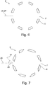
- a cross section of a rotary tumbler 2 is shown.
- the rotary tumbler 2 has a circumferential wall 6 with perforation openings 7 that are aligned perpendicularly to the circumferential wall.
- Each of the perforation openings 7 has an opening axis 27, which is shown for one perforation opening 7 only.
- the opening axes 27 of all perforation openings 7 are perpendicular to the circumferential wall 6, i.e. a respective surface normal 26 of the circumferential wall 6 is parallel to the opening axis 27.
- the respective surface normal 26 is a surface normal in a mathematical sense, which intersects the circumferential wall in a center position of the respective perforation opening 7.
- Fig. 7 is similar to fig. 6 . Only the perforation openings 7 are aligned obliquely to the circumferential wall 6, i.e. the respective surface normal 26 of the circumferential wall 6 is not parallel to the opening axis 27. This way, the surface normal 26 and the opening axis 27 enclose an angle 28.
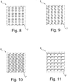
- a section of a surface of a circumferential wall 6 is shown.
- a multitude of equally shaped perforation openings 7 is arranged uniformly, i.e. with constant spacings in between adjacent perforation openings 7.
- the perforation openings 7 have an elliptical shape.
- Fig. 9 is similar to fig. 8 . Only the perforation openings 7 here are oriented in a different way.
- Fig. 10 is similar to fig. 9 . Only the perforation openings 7 here have a different, but still elliptical, shape.
- Fig. 11 is similar to fig. 8 to 10 . Only the perforation openings 7 here have an L-shape.
Landscapes
- Engineering & Computer Science (AREA)
- Life Sciences & Earth Sciences (AREA)
- Chemical & Material Sciences (AREA)
- Polymers & Plastics (AREA)
- Food Science & Technology (AREA)
- Zoology (AREA)
- Wood Science & Technology (AREA)
- Physics & Mathematics (AREA)
- General Engineering & Computer Science (AREA)
- Thermal Sciences (AREA)
- Mechanical Engineering (AREA)
- Combustion & Propulsion (AREA)
- Chemical Kinetics & Catalysis (AREA)
- General Chemical & Material Sciences (AREA)
Priority Applications (3)
| Application Number | Priority Date | Filing Date | Title |
|---|---|---|---|
| PL16159983.2T PL3216352T3 (pl) | 2016-03-11 | 2016-03-11 | Urządzenie chłodzące i sposób chłodzenia przesypywanych artykułów |
| EP16159983.2A EP3216352B1 (de) | 2016-03-11 | 2016-03-11 | Kühlvorrichtung und verfahren zum kühlen von rieselfähigen elementen |
| ES16159983T ES2973054T3 (es) | 2016-03-11 | 2016-03-11 | Dispositivo de enfriamiento y método para enfriar artículos que se pueden verter |
Applications Claiming Priority (1)
| Application Number | Priority Date | Filing Date | Title |
|---|---|---|---|
| EP16159983.2A EP3216352B1 (de) | 2016-03-11 | 2016-03-11 | Kühlvorrichtung und verfahren zum kühlen von rieselfähigen elementen |
Publications (2)
| Publication Number | Publication Date |
|---|---|
| EP3216352A1 true EP3216352A1 (de) | 2017-09-13 |
| EP3216352B1 EP3216352B1 (de) | 2023-12-20 |
Family
ID=55646282
Family Applications (1)
| Application Number | Title | Priority Date | Filing Date |
|---|---|---|---|
| EP16159983.2A Active EP3216352B1 (de) | 2016-03-11 | 2016-03-11 | Kühlvorrichtung und verfahren zum kühlen von rieselfähigen elementen |
Country Status (3)
| Country | Link |
|---|---|
| EP (1) | EP3216352B1 (de) |
| ES (1) | ES2973054T3 (de) |
| PL (1) | PL3216352T3 (de) |
Cited By (3)
| Publication number | Priority date | Publication date | Assignee | Title |
|---|---|---|---|---|
| EP3395183A1 (de) * | 2017-04-28 | 2018-10-31 | Air Liquide Deutschland GmbH | Kühlungsvorrichtung zum kühlen fliessfähiger artikel und verwendung davon |
| WO2023233660A1 (en) * | 2022-06-03 | 2023-12-07 | Mayekawa Mfg. Co., Ltd. | Particles object freezing device |
| WO2023233659A1 (en) * | 2022-06-03 | 2023-12-07 | Mayekawa Mfg. Co., Ltd. | Particles object freezing device |
Citations (4)
| Publication number | Priority date | Publication date | Assignee | Title |
|---|---|---|---|---|
| US5752431A (en) * | 1996-10-15 | 1998-05-19 | Zittel; David R. | Blancher with multiple cooling zones |
| WO2004017000A1 (en) * | 2002-08-16 | 2004-02-26 | The Boc Group, Inc. | Method and apparatus for surface crust freezing of food products |
| EP1704783A1 (de) * | 2005-03-25 | 2006-09-27 | Lyco Manufacturing, Inc. | Drehrohr, -kocher, und -kühler mit Überführungsvorrichtung für das behandelte Produkt |
| WO2008106454A1 (en) * | 2007-02-26 | 2008-09-04 | Blentech Corporation | Continuous food product cooling system |
-
2016
- 2016-03-11 EP EP16159983.2A patent/EP3216352B1/de active Active
- 2016-03-11 PL PL16159983.2T patent/PL3216352T3/pl unknown
- 2016-03-11 ES ES16159983T patent/ES2973054T3/es active Active
Patent Citations (4)
| Publication number | Priority date | Publication date | Assignee | Title |
|---|---|---|---|---|
| US5752431A (en) * | 1996-10-15 | 1998-05-19 | Zittel; David R. | Blancher with multiple cooling zones |
| WO2004017000A1 (en) * | 2002-08-16 | 2004-02-26 | The Boc Group, Inc. | Method and apparatus for surface crust freezing of food products |
| EP1704783A1 (de) * | 2005-03-25 | 2006-09-27 | Lyco Manufacturing, Inc. | Drehrohr, -kocher, und -kühler mit Überführungsvorrichtung für das behandelte Produkt |
| WO2008106454A1 (en) * | 2007-02-26 | 2008-09-04 | Blentech Corporation | Continuous food product cooling system |
Cited By (6)
| Publication number | Priority date | Publication date | Assignee | Title |
|---|---|---|---|---|
| EP3395183A1 (de) * | 2017-04-28 | 2018-10-31 | Air Liquide Deutschland GmbH | Kühlungsvorrichtung zum kühlen fliessfähiger artikel und verwendung davon |
| WO2023233660A1 (en) * | 2022-06-03 | 2023-12-07 | Mayekawa Mfg. Co., Ltd. | Particles object freezing device |
| WO2023233659A1 (en) * | 2022-06-03 | 2023-12-07 | Mayekawa Mfg. Co., Ltd. | Particles object freezing device |
| JP2024524791A (ja) * | 2022-06-03 | 2024-07-09 | 株式会社前川製作所 | 粒状物凍結装置 |
| US12345461B2 (en) | 2022-06-03 | 2025-07-01 | Mayekawa Mfg. Co., Ltd. | Particles object freezing device |
| US12392539B2 (en) | 2022-06-03 | 2025-08-19 | Mayekawa Mfg. Co., Ltd. | Particles object freezing device |
Also Published As
| Publication number | Publication date |
|---|---|
| PL3216352T3 (pl) | 2024-04-29 |
| EP3216352B1 (de) | 2023-12-20 |
| ES2973054T3 (es) | 2024-06-18 |
Similar Documents
| Publication | Publication Date | Title |
|---|---|---|
| EP0923883B1 (de) | Beschichtungstrommel | |
| EP3216352B1 (de) | Kühlvorrichtung und verfahren zum kühlen von rieselfähigen elementen | |
| US20190269148A1 (en) | Device and method for preparing cooled or frozen products | |
| ES2732227T3 (es) | Método y aparato de congelación criogénica | |
| US5868000A (en) | Auger type poultry chiller with clumping prevention | |
| EP3009006B1 (de) | Vorrichtung, System und Verfahren zur Behandlung eines fließfähigen Produkts | |
| US5765381A (en) | Multitier crossflow cryogenic freezer and method of use | |
| US6228172B1 (en) | Tumble coating | |
| US6713107B2 (en) | Airflow distribution systems for food processors | |
| EP3290834B1 (de) | Impinger zum kühlen oder gefrieren von produkten und zugehöriges verfahren | |
| JP6685984B2 (ja) | 連続式冷凍庫 | |
| KR20180036035A (ko) | 식품용 급속 동결장치 | |
| EP3547880B1 (de) | Kühler mit regalkammer | |
| CN107202461A (zh) | 一种液氮冷冻设备的液氮控制系统 | |
| US9791201B1 (en) | Spiral chiller apparatus and method of chilling | |
| JP6963248B2 (ja) | 食品冷却装置 | |
| EP3502596B1 (de) | Vorrichtung und verfahren zur kühlung von produkten | |
| EP3395183A1 (de) | Kühlungsvorrichtung zum kühlen fliessfähiger artikel und verwendung davon | |
| EP3502595B1 (de) | Vorrichtung und verfahren zur kühlung von produkten | |
| EP3318825B1 (de) | Verfahren und vorrichtung zum kühlen von gegenständen mittels einer kryogenen flüssigkeit mittels oszillierenden fluidseparationsdüsen | |
| EP3764030A1 (de) | Verfahren und vorrichtung zur kühlung von produkten | |
| KR101243222B1 (ko) | 급속 냉동용 공기 분배 유닛 | |
| JP2020016387A (ja) | 食品の冷凍装置及び食品の冷凍方法 | |
| EP3502594A1 (de) | Vorrichtung und verfahren zur kühlung von produkten | |
| JP2019113224A (ja) | 冷却装置 |
Legal Events
| Date | Code | Title | Description |
|---|---|---|---|
| PUAI | Public reference made under article 153(3) epc to a published international application that has entered the european phase |
Free format text: ORIGINAL CODE: 0009012 |
|
| STAA | Information on the status of an ep patent application or granted ep patent |
Free format text: STATUS: THE APPLICATION HAS BEEN PUBLISHED |
|
| AK | Designated contracting states |
Kind code of ref document: A1 Designated state(s): AL AT BE BG CH CY CZ DE DK EE ES FI FR GB GR HR HU IE IS IT LI LT LU LV MC MK MT NL NO PL PT RO RS SE SI SK SM TR |
|
| AX | Request for extension of the european patent |
Extension state: BA ME |
|
| STAA | Information on the status of an ep patent application or granted ep patent |
Free format text: STATUS: REQUEST FOR EXAMINATION WAS MADE |
|
| 17P | Request for examination filed |
Effective date: 20180312 |
|
| RBV | Designated contracting states (corrected) |
Designated state(s): AL AT BE BG CH CY CZ DE DK EE ES FI FR GB GR HR HU IE IS IT LI LT LU LV MC MK MT NL NO PL PT RO RS SE SI SK SM TR |
|
| STAA | Information on the status of an ep patent application or granted ep patent |
Free format text: STATUS: EXAMINATION IS IN PROGRESS |
|
| RIN1 | Information on inventor provided before grant (corrected) |
Inventor name: ANGENHEISTER DE FREITAS, ALEXANDER |
|
| 17Q | First examination report despatched |
Effective date: 20190715 |
|
| GRAP | Despatch of communication of intention to grant a patent |
Free format text: ORIGINAL CODE: EPIDOSNIGR1 |
|
| STAA | Information on the status of an ep patent application or granted ep patent |
Free format text: STATUS: GRANT OF PATENT IS INTENDED |
|
| RIC1 | Information provided on ipc code assigned before grant |
Ipc: A23L 3/375 20060101ALI20230710BHEP Ipc: A23B 4/08 20060101ALI20230710BHEP Ipc: F25D 13/06 20060101ALI20230710BHEP Ipc: A22C 9/00 20060101ALI20230710BHEP Ipc: A23B 4/06 20060101ALI20230710BHEP Ipc: A23L 3/36 20060101AFI20230710BHEP |
|
| INTG | Intention to grant announced |
Effective date: 20230731 |
|
| GRAS | Grant fee paid |
Free format text: ORIGINAL CODE: EPIDOSNIGR3 |
|
| GRAA | (expected) grant |
Free format text: ORIGINAL CODE: 0009210 |
|
| STAA | Information on the status of an ep patent application or granted ep patent |
Free format text: STATUS: THE PATENT HAS BEEN GRANTED |
|
| RAP3 | Party data changed (applicant data changed or rights of an application transferred) |
Owner name: L'AIR LIQUIDE, SOCIETE ANONYME POUR L'ETUDE ET L'EXPLOITATION DES PROCEDES GEORGES CLAUDE Owner name: AIR LIQUIDE DEUTSCHLAND GMBH |
|
| AK | Designated contracting states |
Kind code of ref document: B1 Designated state(s): AL AT BE BG CH CY CZ DE DK EE ES FI FR GB GR HR HU IE IS IT LI LT LU LV MC MK MT NL NO PL PT RO RS SE SI SK SM TR |
|
| REG | Reference to a national code |
Ref country code: GB Ref legal event code: FG4D |
|
| REG | Reference to a national code |
Ref country code: DE Ref legal event code: R096 Ref document number: 602016084807 Country of ref document: DE |
|
| REG | Reference to a national code |
Ref country code: CH Ref legal event code: EP |
|
| REG | Reference to a national code |
Ref country code: IE Ref legal event code: FG4D |
|
| REG | Reference to a national code |
Ref country code: NL Ref legal event code: FP |
|
| PG25 | Lapsed in a contracting state [announced via postgrant information from national office to epo] |
Ref country code: GR Free format text: LAPSE BECAUSE OF FAILURE TO SUBMIT A TRANSLATION OF THE DESCRIPTION OR TO PAY THE FEE WITHIN THE PRESCRIBED TIME-LIMIT Effective date: 20240321 |
|
| REG | Reference to a national code |
Ref country code: LT Ref legal event code: MG9D |
|
| PG25 | Lapsed in a contracting state [announced via postgrant information from national office to epo] |
Ref country code: LT Free format text: LAPSE BECAUSE OF FAILURE TO SUBMIT A TRANSLATION OF THE DESCRIPTION OR TO PAY THE FEE WITHIN THE PRESCRIBED TIME-LIMIT Effective date: 20231220 |
|
| PG25 | Lapsed in a contracting state [announced via postgrant information from national office to epo] |
Ref country code: LT Free format text: LAPSE BECAUSE OF FAILURE TO SUBMIT A TRANSLATION OF THE DESCRIPTION OR TO PAY THE FEE WITHIN THE PRESCRIBED TIME-LIMIT Effective date: 20231220 Ref country code: GR Free format text: LAPSE BECAUSE OF FAILURE TO SUBMIT A TRANSLATION OF THE DESCRIPTION OR TO PAY THE FEE WITHIN THE PRESCRIBED TIME-LIMIT Effective date: 20240321 Ref country code: FI Free format text: LAPSE BECAUSE OF FAILURE TO SUBMIT A TRANSLATION OF THE DESCRIPTION OR TO PAY THE FEE WITHIN THE PRESCRIBED TIME-LIMIT Effective date: 20231220 Ref country code: BG Free format text: LAPSE BECAUSE OF FAILURE TO SUBMIT A TRANSLATION OF THE DESCRIPTION OR TO PAY THE FEE WITHIN THE PRESCRIBED TIME-LIMIT Effective date: 20240320 |
|
| REG | Reference to a national code |
Ref country code: AT Ref legal event code: MK05 Ref document number: 1641646 Country of ref document: AT Kind code of ref document: T Effective date: 20231220 |
|
| PG25 | Lapsed in a contracting state [announced via postgrant information from national office to epo] |
Ref country code: SE Free format text: LAPSE BECAUSE OF FAILURE TO SUBMIT A TRANSLATION OF THE DESCRIPTION OR TO PAY THE FEE WITHIN THE PRESCRIBED TIME-LIMIT Effective date: 20231220 Ref country code: RS Free format text: LAPSE BECAUSE OF FAILURE TO SUBMIT A TRANSLATION OF THE DESCRIPTION OR TO PAY THE FEE WITHIN THE PRESCRIBED TIME-LIMIT Effective date: 20231220 Ref country code: NO Free format text: LAPSE BECAUSE OF FAILURE TO SUBMIT A TRANSLATION OF THE DESCRIPTION OR TO PAY THE FEE WITHIN THE PRESCRIBED TIME-LIMIT Effective date: 20240320 Ref country code: LV Free format text: LAPSE BECAUSE OF FAILURE TO SUBMIT A TRANSLATION OF THE DESCRIPTION OR TO PAY THE FEE WITHIN THE PRESCRIBED TIME-LIMIT Effective date: 20231220 Ref country code: HR Free format text: LAPSE BECAUSE OF FAILURE TO SUBMIT A TRANSLATION OF THE DESCRIPTION OR TO PAY THE FEE WITHIN THE PRESCRIBED TIME-LIMIT Effective date: 20231220 |
|
| REG | Reference to a national code |
Ref country code: ES Ref legal event code: FG2A Ref document number: 2973054 Country of ref document: ES Kind code of ref document: T3 Effective date: 20240618 |
|
| PG25 | Lapsed in a contracting state [announced via postgrant information from national office to epo] |
Ref country code: IS Free format text: LAPSE BECAUSE OF FAILURE TO SUBMIT A TRANSLATION OF THE DESCRIPTION OR TO PAY THE FEE WITHIN THE PRESCRIBED TIME-LIMIT Effective date: 20240420 |
|
| PG25 | Lapsed in a contracting state [announced via postgrant information from national office to epo] |
Ref country code: CZ Free format text: LAPSE BECAUSE OF FAILURE TO SUBMIT A TRANSLATION OF THE DESCRIPTION OR TO PAY THE FEE WITHIN THE PRESCRIBED TIME-LIMIT Effective date: 20231220 Ref country code: AT Free format text: LAPSE BECAUSE OF FAILURE TO SUBMIT A TRANSLATION OF THE DESCRIPTION OR TO PAY THE FEE WITHIN THE PRESCRIBED TIME-LIMIT Effective date: 20231220 |
|
| PG25 | Lapsed in a contracting state [announced via postgrant information from national office to epo] |
Ref country code: SK Free format text: LAPSE BECAUSE OF FAILURE TO SUBMIT A TRANSLATION OF THE DESCRIPTION OR TO PAY THE FEE WITHIN THE PRESCRIBED TIME-LIMIT Effective date: 20231220 |
|
| PG25 | Lapsed in a contracting state [announced via postgrant information from national office to epo] |
Ref country code: SM Free format text: LAPSE BECAUSE OF FAILURE TO SUBMIT A TRANSLATION OF THE DESCRIPTION OR TO PAY THE FEE WITHIN THE PRESCRIBED TIME-LIMIT Effective date: 20231220 Ref country code: SK Free format text: LAPSE BECAUSE OF FAILURE TO SUBMIT A TRANSLATION OF THE DESCRIPTION OR TO PAY THE FEE WITHIN THE PRESCRIBED TIME-LIMIT Effective date: 20231220 Ref country code: RO Free format text: LAPSE BECAUSE OF FAILURE TO SUBMIT A TRANSLATION OF THE DESCRIPTION OR TO PAY THE FEE WITHIN THE PRESCRIBED TIME-LIMIT Effective date: 20231220 Ref country code: IS Free format text: LAPSE BECAUSE OF FAILURE TO SUBMIT A TRANSLATION OF THE DESCRIPTION OR TO PAY THE FEE WITHIN THE PRESCRIBED TIME-LIMIT Effective date: 20240420 Ref country code: EE Free format text: LAPSE BECAUSE OF FAILURE TO SUBMIT A TRANSLATION OF THE DESCRIPTION OR TO PAY THE FEE WITHIN THE PRESCRIBED TIME-LIMIT Effective date: 20231220 Ref country code: CZ Free format text: LAPSE BECAUSE OF FAILURE TO SUBMIT A TRANSLATION OF THE DESCRIPTION OR TO PAY THE FEE WITHIN THE PRESCRIBED TIME-LIMIT Effective date: 20231220 Ref country code: AT Free format text: LAPSE BECAUSE OF FAILURE TO SUBMIT A TRANSLATION OF THE DESCRIPTION OR TO PAY THE FEE WITHIN THE PRESCRIBED TIME-LIMIT Effective date: 20231220 |
|
| PG25 | Lapsed in a contracting state [announced via postgrant information from national office to epo] |
Ref country code: PT Free format text: LAPSE BECAUSE OF FAILURE TO SUBMIT A TRANSLATION OF THE DESCRIPTION OR TO PAY THE FEE WITHIN THE PRESCRIBED TIME-LIMIT Effective date: 20240422 |
|
| PG25 | Lapsed in a contracting state [announced via postgrant information from national office to epo] |
Ref country code: PT Free format text: LAPSE BECAUSE OF FAILURE TO SUBMIT A TRANSLATION OF THE DESCRIPTION OR TO PAY THE FEE WITHIN THE PRESCRIBED TIME-LIMIT Effective date: 20240422 |
|
| REG | Reference to a national code |
Ref country code: DE Ref legal event code: R097 Ref document number: 602016084807 Country of ref document: DE |
|
| PG25 | Lapsed in a contracting state [announced via postgrant information from national office to epo] |
Ref country code: DK Free format text: LAPSE BECAUSE OF FAILURE TO SUBMIT A TRANSLATION OF THE DESCRIPTION OR TO PAY THE FEE WITHIN THE PRESCRIBED TIME-LIMIT Effective date: 20231220 |
|
| PLBE | No opposition filed within time limit |
Free format text: ORIGINAL CODE: 0009261 |
|
| STAA | Information on the status of an ep patent application or granted ep patent |
Free format text: STATUS: NO OPPOSITION FILED WITHIN TIME LIMIT |
|
| PG25 | Lapsed in a contracting state [announced via postgrant information from national office to epo] |
Ref country code: SI Free format text: LAPSE BECAUSE OF FAILURE TO SUBMIT A TRANSLATION OF THE DESCRIPTION OR TO PAY THE FEE WITHIN THE PRESCRIBED TIME-LIMIT Effective date: 20231220 |
|
| PG25 | Lapsed in a contracting state [announced via postgrant information from national office to epo] |
Ref country code: SI Free format text: LAPSE BECAUSE OF FAILURE TO SUBMIT A TRANSLATION OF THE DESCRIPTION OR TO PAY THE FEE WITHIN THE PRESCRIBED TIME-LIMIT Effective date: 20231220 Ref country code: DK Free format text: LAPSE BECAUSE OF FAILURE TO SUBMIT A TRANSLATION OF THE DESCRIPTION OR TO PAY THE FEE WITHIN THE PRESCRIBED TIME-LIMIT Effective date: 20231220 |
|
| REG | Reference to a national code |
Ref country code: CH Ref legal event code: PL |
|
| PG25 | Lapsed in a contracting state [announced via postgrant information from national office to epo] |
Ref country code: LU Free format text: LAPSE BECAUSE OF NON-PAYMENT OF DUE FEES Effective date: 20240311 |
|
| PG25 | Lapsed in a contracting state [announced via postgrant information from national office to epo] |
Ref country code: MC Free format text: LAPSE BECAUSE OF FAILURE TO SUBMIT A TRANSLATION OF THE DESCRIPTION OR TO PAY THE FEE WITHIN THE PRESCRIBED TIME-LIMIT Effective date: 20231220 |
|
| REG | Reference to a national code |
Ref country code: DE Ref legal event code: R079 Ref document number: 602016084807 Country of ref document: DE Free format text: PREVIOUS MAIN CLASS: A23L0003360000 Ipc: A23B0002800000 |
|
| 26N | No opposition filed |
Effective date: 20240923 |
|
| GBPC | Gb: european patent ceased through non-payment of renewal fee |
Effective date: 20240320 |
|
| PG25 | Lapsed in a contracting state [announced via postgrant information from national office to epo] |
Ref country code: MC Free format text: LAPSE BECAUSE OF FAILURE TO SUBMIT A TRANSLATION OF THE DESCRIPTION OR TO PAY THE FEE WITHIN THE PRESCRIBED TIME-LIMIT Effective date: 20231220 Ref country code: LU Free format text: LAPSE BECAUSE OF NON-PAYMENT OF DUE FEES Effective date: 20240311 |
|
| REG | Reference to a national code |
Ref country code: BE Ref legal event code: MM Effective date: 20240331 |
|
| PG25 | Lapsed in a contracting state [announced via postgrant information from national office to epo] |
Ref country code: BE Free format text: LAPSE BECAUSE OF NON-PAYMENT OF DUE FEES Effective date: 20240331 |
|
| PG25 | Lapsed in a contracting state [announced via postgrant information from national office to epo] |
Ref country code: GB Free format text: LAPSE BECAUSE OF NON-PAYMENT OF DUE FEES Effective date: 20240320 |
|
| PG25 | Lapsed in a contracting state [announced via postgrant information from national office to epo] |
Ref country code: IE Free format text: LAPSE BECAUSE OF NON-PAYMENT OF DUE FEES Effective date: 20240311 |
|
| PG25 | Lapsed in a contracting state [announced via postgrant information from national office to epo] |
Ref country code: IE Free format text: LAPSE BECAUSE OF NON-PAYMENT OF DUE FEES Effective date: 20240311 Ref country code: GB Free format text: LAPSE BECAUSE OF NON-PAYMENT OF DUE FEES Effective date: 20240320 Ref country code: BE Free format text: LAPSE BECAUSE OF NON-PAYMENT OF DUE FEES Effective date: 20240331 Ref country code: CH Free format text: LAPSE BECAUSE OF NON-PAYMENT OF DUE FEES Effective date: 20240331 |
|
| PGFP | Annual fee paid to national office [announced via postgrant information from national office to epo] |
Ref country code: PL Payment date: 20250303 Year of fee payment: 10 |
|
| PGFP | Annual fee paid to national office [announced via postgrant information from national office to epo] |
Ref country code: ES Payment date: 20250429 Year of fee payment: 10 |
|
| PG25 | Lapsed in a contracting state [announced via postgrant information from national office to epo] |
Ref country code: CY Free format text: LAPSE BECAUSE OF FAILURE TO SUBMIT A TRANSLATION OF THE DESCRIPTION OR TO PAY THE FEE WITHIN THE PRESCRIBED TIME-LIMIT; INVALID AB INITIO Effective date: 20160311 |
|
| PG25 | Lapsed in a contracting state [announced via postgrant information from national office to epo] |
Ref country code: HU Free format text: LAPSE BECAUSE OF FAILURE TO SUBMIT A TRANSLATION OF THE DESCRIPTION OR TO PAY THE FEE WITHIN THE PRESCRIBED TIME-LIMIT; INVALID AB INITIO Effective date: 20160311 |
|
| PG25 | Lapsed in a contracting state [announced via postgrant information from national office to epo] |
Ref country code: TR Free format text: LAPSE BECAUSE OF FAILURE TO SUBMIT A TRANSLATION OF THE DESCRIPTION OR TO PAY THE FEE WITHIN THE PRESCRIBED TIME-LIMIT Effective date: 20231220 |
|
| PGFP | Annual fee paid to national office [announced via postgrant information from national office to epo] |
Ref country code: DE Payment date: 20260319 Year of fee payment: 11 |
|
| PGFP | Annual fee paid to national office [announced via postgrant information from national office to epo] |
Ref country code: IT Payment date: 20260319 Year of fee payment: 11 |
|
| PGFP | Annual fee paid to national office [announced via postgrant information from national office to epo] |
Ref country code: NL Payment date: 20260319 Year of fee payment: 11 |
|
| PGFP | Annual fee paid to national office [announced via postgrant information from national office to epo] |
Ref country code: FR Payment date: 20260320 Year of fee payment: 11 |