EP3216355A1 - Tête de coupe pour article à fumer de forme allongée - Google Patents
Tête de coupe pour article à fumer de forme allongée Download PDFInfo
- Publication number
- EP3216355A1 EP3216355A1 EP17158964.1A EP17158964A EP3216355A1 EP 3216355 A1 EP3216355 A1 EP 3216355A1 EP 17158964 A EP17158964 A EP 17158964A EP 3216355 A1 EP3216355 A1 EP 3216355A1
- Authority
- EP
- European Patent Office
- Prior art keywords
- circular blade
- cutting
- cutting head
- scraping
- rotation
- Prior art date
- Legal status (The legal status is an assumption and is not a legal conclusion. Google has not performed a legal analysis and makes no representation as to the accuracy of the status listed.)
- Granted
Links
Images


Classifications
-
- B—PERFORMING OPERATIONS; TRANSPORTING
- B26—HAND CUTTING TOOLS; CUTTING; SEVERING
- B26D—CUTTING; DETAILS COMMON TO MACHINES FOR PERFORATING, PUNCHING, CUTTING-OUT, STAMPING-OUT OR SEVERING
- B26D1/00—Cutting through work characterised by the nature or movement of the cutting member or particular materials not otherwise provided for; Apparatus or machines therefor; Cutting members therefor
- B26D1/01—Cutting through work characterised by the nature or movement of the cutting member or particular materials not otherwise provided for; Apparatus or machines therefor; Cutting members therefor involving a cutting member which does not travel with the work
- B26D1/12—Cutting through work characterised by the nature or movement of the cutting member or particular materials not otherwise provided for; Apparatus or machines therefor; Cutting members therefor involving a cutting member which does not travel with the work having a cutting member moving about an axis
- B26D1/14—Cutting through work characterised by the nature or movement of the cutting member or particular materials not otherwise provided for; Apparatus or machines therefor; Cutting members therefor involving a cutting member which does not travel with the work having a cutting member moving about an axis with a circular cutting member, e.g. disc cutter
-
- A—HUMAN NECESSITIES
- A24—TOBACCO; CIGARS; CIGARETTES; SIMULATED SMOKING DEVICES; SMOKERS' REQUISITES
- A24C—MACHINES FOR MAKING CIGARS OR CIGARETTES
- A24C5/00—Making cigarettes; Making tipping materials for, or attaching filters or mouthpieces to, cigars or cigarettes
- A24C5/14—Machines of the continuous-rod type
- A24C5/28—Cutting-off the tobacco rod
-
- B—PERFORMING OPERATIONS; TRANSPORTING
- B26—HAND CUTTING TOOLS; CUTTING; SEVERING
- B26D—CUTTING; DETAILS COMMON TO MACHINES FOR PERFORATING, PUNCHING, CUTTING-OUT, STAMPING-OUT OR SEVERING
- B26D1/00—Cutting through work characterised by the nature or movement of the cutting member or particular materials not otherwise provided for; Apparatus or machines therefor; Cutting members therefor
- B26D1/01—Cutting through work characterised by the nature or movement of the cutting member or particular materials not otherwise provided for; Apparatus or machines therefor; Cutting members therefor involving a cutting member which does not travel with the work
- B26D1/12—Cutting through work characterised by the nature or movement of the cutting member or particular materials not otherwise provided for; Apparatus or machines therefor; Cutting members therefor involving a cutting member which does not travel with the work having a cutting member moving about an axis
- B26D1/14—Cutting through work characterised by the nature or movement of the cutting member or particular materials not otherwise provided for; Apparatus or machines therefor; Cutting members therefor involving a cutting member which does not travel with the work having a cutting member moving about an axis with a circular cutting member, e.g. disc cutter
- B26D1/143—Cutting through work characterised by the nature or movement of the cutting member or particular materials not otherwise provided for; Apparatus or machines therefor; Cutting members therefor involving a cutting member which does not travel with the work having a cutting member moving about an axis with a circular cutting member, e.g. disc cutter rotating about a stationary axis
- B26D1/15—Cutting through work characterised by the nature or movement of the cutting member or particular materials not otherwise provided for; Apparatus or machines therefor; Cutting members therefor involving a cutting member which does not travel with the work having a cutting member moving about an axis with a circular cutting member, e.g. disc cutter rotating about a stationary axis with vertical cutting member
- B26D1/151—Cutting through work characterised by the nature or movement of the cutting member or particular materials not otherwise provided for; Apparatus or machines therefor; Cutting members therefor involving a cutting member which does not travel with the work having a cutting member moving about an axis with a circular cutting member, e.g. disc cutter rotating about a stationary axis with vertical cutting member for thin material, e.g. for sheets, strips or the like
-
- B—PERFORMING OPERATIONS; TRANSPORTING
- B26—HAND CUTTING TOOLS; CUTTING; SEVERING
- B26D—CUTTING; DETAILS COMMON TO MACHINES FOR PERFORATING, PUNCHING, CUTTING-OUT, STAMPING-OUT OR SEVERING
- B26D1/00—Cutting through work characterised by the nature or movement of the cutting member or particular materials not otherwise provided for; Apparatus or machines therefor; Cutting members therefor
- B26D1/01—Cutting through work characterised by the nature or movement of the cutting member or particular materials not otherwise provided for; Apparatus or machines therefor; Cutting members therefor involving a cutting member which does not travel with the work
- B26D1/12—Cutting through work characterised by the nature or movement of the cutting member or particular materials not otherwise provided for; Apparatus or machines therefor; Cutting members therefor involving a cutting member which does not travel with the work having a cutting member moving about an axis
- B26D1/14—Cutting through work characterised by the nature or movement of the cutting member or particular materials not otherwise provided for; Apparatus or machines therefor; Cutting members therefor involving a cutting member which does not travel with the work having a cutting member moving about an axis with a circular cutting member, e.g. disc cutter
- B26D1/24—Cutting through work characterised by the nature or movement of the cutting member or particular materials not otherwise provided for; Apparatus or machines therefor; Cutting members therefor involving a cutting member which does not travel with the work having a cutting member moving about an axis with a circular cutting member, e.g. disc cutter coacting with another disc cutter
- B26D1/245—Cutting through work characterised by the nature or movement of the cutting member or particular materials not otherwise provided for; Apparatus or machines therefor; Cutting members therefor involving a cutting member which does not travel with the work having a cutting member moving about an axis with a circular cutting member, e.g. disc cutter coacting with another disc cutter for thin material, e.g. for sheets, strips or the like
-
- B—PERFORMING OPERATIONS; TRANSPORTING
- B26—HAND CUTTING TOOLS; CUTTING; SEVERING
- B26D—CUTTING; DETAILS COMMON TO MACHINES FOR PERFORATING, PUNCHING, CUTTING-OUT, STAMPING-OUT OR SEVERING
- B26D5/00—Arrangements for operating and controlling machines or devices for cutting, cutting-out, stamping-out, punching, perforating, or severing by means other than cutting
- B26D5/02—Means for moving the cutting member into its operative position for cutting
- B26D5/06—Means for moving the cutting member into its operative position for cutting by electrical means
-
- B—PERFORMING OPERATIONS; TRANSPORTING
- B26—HAND CUTTING TOOLS; CUTTING; SEVERING
- B26D—CUTTING; DETAILS COMMON TO MACHINES FOR PERFORATING, PUNCHING, CUTTING-OUT, STAMPING-OUT OR SEVERING
- B26D7/00—Details of apparatus for cutting, cutting-out, stamping-out, punching, perforating, or severing by means other than cutting
- B26D7/08—Means for treating work or cutting member to facilitate cutting
- B26D7/088—Means for treating work or cutting member to facilitate cutting by cleaning or lubricating
-
- B—PERFORMING OPERATIONS; TRANSPORTING
- B26—HAND CUTTING TOOLS; CUTTING; SEVERING
- B26D—CUTTING; DETAILS COMMON TO MACHINES FOR PERFORATING, PUNCHING, CUTTING-OUT, STAMPING-OUT OR SEVERING
- B26D7/00—Details of apparatus for cutting, cutting-out, stamping-out, punching, perforating, or severing by means other than cutting
- B26D7/18—Means for removing cut-out material or waste
- B26D7/1845—Means for removing cut-out material or waste by non mechanical means
- B26D7/1854—Means for removing cut-out material or waste by non mechanical means by air under pressure
-
- B—PERFORMING OPERATIONS; TRANSPORTING
- B26—HAND CUTTING TOOLS; CUTTING; SEVERING
- B26D—CUTTING; DETAILS COMMON TO MACHINES FOR PERFORATING, PUNCHING, CUTTING-OUT, STAMPING-OUT OR SEVERING
- B26D7/00—Details of apparatus for cutting, cutting-out, stamping-out, punching, perforating, or severing by means other than cutting
- B26D7/26—Means for mounting or adjusting the cutting member; Means for adjusting the stroke of the cutting member
- B26D7/2628—Means for adjusting the position of the cutting member
- B26D7/2635—Means for adjusting the position of the cutting member for circular cutters
Definitions
- This invention relates to a cutting head for cutting rod-shaped pieces in machines for making smokers' articles.
- rod-shaped piece preferably includes pieces of filter or cigarette processed prior to obtaining a finished cigarette.
- the cutting head of this invention can be applied to a filter tip attachment machine in cigarette making machine, where pieces of filter are applied to corresponding pieces of cigarette.
- the cutting head of this invention can be advantageously applied to cutting composite filters of the type which are externally covered by an impermeable plastic sheath ("filter tube").
- Prior art cutting heads comprise a circular blade made of metallic material.
- the blade cyclically severs a double-length piece of filter or cigarette, dividing it into two single-length pieces.
- Filter tip attachment machines comprise feed drums for feeding double length pieces of cigarette which are each divided into two single length pieces by a first circular cutting blade.
- the two pieces of cigarette thus obtained are axially spaced by a spacing drum and, in a drum following that, a double-length piece of filter is inserted between them and joined to the pieces of cigarette by wrapping in a sheet of paper material.
- the double-length piece of filter is then cut into two in a yet further drum by another circular cutting blade in such a way as to obtain two cigarettes placed end to end with their filter tips.
- the blade is subject to heating which interacts negatively with the filter material which tends to stick to the surface of the blade, especially on the peripheral zone of it defining the cutting edge.
- Repeated cutting causes the filter material to build up on the blade, reducing the cutting properties of the blade and thus worsening the quality of the cut pieces of filter.
- the basic technical purpose of this invention is to provide a cutting head for cutting rod-shaped pieces in machines for making smokers' articles to overcome the above mentioned disadvantages of the prior art.
- this invention has for an aim to provide a cutting head for cutting rod-shaped pieces in machines for making smokers' articles which is capable of guaranteeing lasting high cutting quality by eliminating the problem of rapid wear.
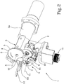
- the numeral 1 denotes in its entirety a cutting head for cutting rod-shaped pieces in machines for making smokers' articles according to this invention.
- the cutting head 1 comprises a circular blade 2 mounted on a supporting frame 3 and driven in rotation about its axis "X" by drive means which, for example, comprise a motor (not illustrated) inside the supporting frame 3 or other means for connecting it to drive means (not illustrated).
- drive means which, for example, comprise a motor (not illustrated) inside the supporting frame 3 or other means for connecting it to drive means (not illustrated).
- the cutting head 1 shown in the accompanying drawings with some parts cut away in order to better illustrate the invention, is preferably located at a filter tip attachment machine where pieces of filter are attached to pieces of cigarette. More in detail, the cutting head 1 is adapted to operate on rod-shaped articles (not illustrated in the accompanying drawings) transported in the suction flutes of a drum transversely to the axis of extension of the rod-shaped articles themselves. In this situation, the cutting head 1 is positioned with the circular blade 2 oriented with its axis "X" parallel to the axis of the rotary drum and thus parallel to the axis of the rod-shaped articles so that the position plane of the circular blade 2 is perpendicular to the rod-shaped articles, enabling the circular blade 2 to cut the articles into two parts.
- the circular blade 2 is located at the end of a substantially tubular portion 3a of the supporting frame 3, aligned with the axis "X" of the circular blade 2.
- the circular blade 2 which is of essentially known type, is defined by a metallic disc which is substantially flat except for an outer circular crown defining a cutting portion 4 which is tapered towards the cutting edge 5 in such a way as to define a rake angle "S" relative to the flat front surfaces of the circular blade 2 ( Figure 8 ).
- the rake angle "S" is between 2° and 40°.
- the cutting head 1 comprises scraping means 6 which are at least temporarily in contact with the cutting portion 4 of the circular blade 2 during a working cycle of the blade 2 in order to mechanically remove any residues from the cutting portion 4.
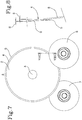
- the scraping means 6 comprise at least one scraping disc 7 rotatable about a respective axis of rotation "Y1" and having a peripheral portion which is kept in contact with the cutting portion 4 of the circular blade 2.
- the scraping means 6 comprise a pair of scraping discs 7, 8 disposed on opposite faces of the cutting portion 4 of the circular blade 2 so that any residues are removed from both sides of the cutting portion 4.
- the two scraping discs 7, 8 have respective axes of rotation "Y1", “Y2" which are inclined in opposite directions, and still more preferably by the same quantity, relative to the axis of rotation "X" of the circular blade 2.
- each scraping disc 7, 8 is inclined relative to the axis of rotation "X" of the circular blade 2 in such a way that the scraping disc 7, 8 can be kept in contact with the cutting portion of the circular blade along a contact line belonging to the cutting portion.
- the axis of rotation "Y1 ", "Y2" of each scraping disc 7, 8 is inclined relative to the axis of rotation "X" of the circular blade 2 at an angle of between 2° and 40°.
- the axes of rotation "Y1", "Y2" of the scraping discs 7, 8 are skew to each other.
- each scraping disc 7, 8 in the zone of contact with the cutting portion 4 of the circular blade 2, each scraping disc 7, 8 is contained in a plane which is inclined oppositely to the rake angle relative to the plane containing the circular blade 2.
- each scraping disc acts on an annular band of the cutting portion 4 whose radial extension is between 0.2 and 10 mm.
- each scraping disc 7 is idle and is driven in rotation about its axis "Y1" by frictional interaction with the circular blade 2.
- the frictional interaction between the circular blade 2 and the scraping discs 7, 8 is only partly tangential and also has a radial component. The tangential components drive the scraping discs 7, 8 in rotation, while the radial components produce the scraping action on the cutting portion 4.
- the scraping means 6 are mounted on a supporting member 9 which is designed to adopt an adjustable position relative to the circular blade 2, in particular according to a translational movement towards and away from it.
- a supporting member 9 which is designed to adopt an adjustable position relative to the circular blade 2, in particular according to a translational movement towards and away from it.
- This is accomplished by mounting the supporting member 9 on the frame 3 by means of a stem 10 which can be driven with precision using a micrometric screw 11. That way, it is possible to compensate for any clearances between the scraping means 6 and the circular blade 2 as a result of wear.
- the supporting member 9 is a rigid, cradle-shaped element which supports the two scraping discs 7, 8 on each side of it and which is connected, centrally, at the bottom of it to the upper end of the stem 10, whose lower end is coupled to the frame 3 and is connected to the aforementioned micrometric screw 11.
- the cutting head 1 also comprises a blowing member 12 acting on at least one face of the circular blade 2 to direct a cooling air jet at the circular blade 2 and, in particular at least at the cutting portion 4 of the circular blade 2.
- the blowing member is configured in such a way as to direct a cooling air flow at both faces of the circular blade 2.
- the blowing member 12 is a U-shaped element having a central housing which receives a peripheral part of the circular blade 2 whose peripheral part is thus enclosed in the blowing member 12.
- the peripheral part of the circular blade 2 acted on by the blowing member 12 extends in a radial direction from the cutting edge 5 for between 0.2 and 10 mm.
- the blowing member 12 is also mounted to the supporting member 9 and, in order to supply compressed air to the blowing member 12, at least one pneumatic fitting 13 is provided for connection to a compressed air supply hose (not illustrated).
- the blowing member 12 is operatively located upstream of at least one of the scraping means 6 (that is, of at least one of the scraping discs 7, 8).
- the scraping means 6 are operatively located at least partly downstream of the blowing member 12.
- blowing member 12 is located at an intermediate position between the two scraping discs 7, 8.
- the cutting head 1 may also comprise at least one auxiliary scraping member 14 operatively positioned substantially in contact with at least one face of the circular blade 2 further on the inner side of the cutting portion 4 and adjacent to the cutting portion 4.
- the auxiliary scraping members 14 act on a different annular zone of the circular blade 2 from that acted upon by the scraping means 6, in particular on a zone in which the faces of the circular blade 2 are parallel to each other and perpendicular to the axis of rotation "X" (that is to say, further in than the cutting portion 4 with the rake angle "S").
- Each auxiliary scraping member 14 thus has a scraping edge which is preferably rectilinear and parallel to the plane defined by the respective face of the circular blade 2 it acts on.
- the auxiliary scraping members 14 are located upstream of the two scraping discs 7, 8 relative to the feed direction of the circular blade 2, that is to say, at a position between the cutting area (labelled "A" in Figure 1 and corresponding to the zone in which the circular blade 2 cuts the rod-shaped articles) and the scraping discs 7, 8.
- the width of the annular band of the circular blade 2 acted on by the auxiliary scraping members 14 substantially coincides with the annular band acted on by the blowing member 12.
- auxiliary scraping members 14 are mounted on a fixed part of the cutting head, in particular on the frame 3, and are therefore not applied to the adjustable supporting member 9.
- the auxiliary scraping members 14 are of adjustable type: in particular, they can be moved towards and away from the faces of the circular blade 2 by tilting about respective hinge axes "Z1 ", "Z2" in order to vary the distance between them and the circular blade 2 and/or to enable or disable their scraping action.
- the cutting head 1 also comprises protective elements to cover at least part of the working zone of the circular blade 2. More specifically, the protective elements, shown in Figure 1 , comprise a face guard 15 covering the zone of interaction between the scraping discs 7, 8 and the circular blade 2 and/or curved protective guards 16 placed around the scraping discs 7, 8. Variants of the invention described in the foregoing are also imaginable without departing from the scope of the inventive concept. In particular, there may be a different number of scraping discs, mounted as required at suitable positions relative to the circular blade.
- the parts of the circular blade acted on by the auxiliary scraping members and/or the blowing member may also differ from each other and from what is described above.
- This invention achieves the preset aim thanks to the distinctive interaction between the action of the scraping discs to remove the residues and the cooling effect of the blowing member on the circular blade, which combine to improve blade cleaning efficiency, thereby increasing blade working life without requiring frequent maintenance to clean or change the blade and with obvious advantages in terms of productivity.
- This effect is particularly important for cutting plastic covered filters because it avoids the build-up of molten plastic residues resulting from the cutting action.
Landscapes
- Life Sciences & Earth Sciences (AREA)
- Forests & Forestry (AREA)
- Engineering & Computer Science (AREA)
- Mechanical Engineering (AREA)
- Cigarettes, Filters, And Manufacturing Of Filters (AREA)
Priority Applications (1)
| Application Number | Priority Date | Filing Date | Title |
|---|---|---|---|
| PL17158964T PL3216355T3 (pl) | 2016-03-10 | 2017-03-02 | Głowica tnąca do cięcia części w kształcie pręta w maszynach do wytwarzania artykułów dla palaczy |
Applications Claiming Priority (1)
| Application Number | Priority Date | Filing Date | Title |
|---|---|---|---|
| ITUA2016A001489A ITUA20161489A1 (it) | 2016-03-10 | 2016-03-10 | Testa di taglio per il taglio di spezzoni a forma di bacchetta in macchine per la produzione di articoli da fumo. |
Publications (2)
| Publication Number | Publication Date |
|---|---|
| EP3216355A1 true EP3216355A1 (fr) | 2017-09-13 |
| EP3216355B1 EP3216355B1 (fr) | 2019-10-02 |
Family
ID=56203584
Family Applications (1)
| Application Number | Title | Priority Date | Filing Date |
|---|---|---|---|
| EP17158964.1A Active EP3216355B1 (fr) | 2016-03-10 | 2017-03-02 | Tête de coupe pour article à fumer de forme allongée |
Country Status (3)
| Country | Link |
|---|---|
| EP (1) | EP3216355B1 (fr) |
| IT (1) | ITUA20161489A1 (fr) |
| PL (1) | PL3216355T3 (fr) |
Cited By (3)
| Publication number | Priority date | Publication date | Assignee | Title |
|---|---|---|---|---|
| CN116001006A (zh) * | 2022-12-21 | 2023-04-25 | 江西中烟工业有限责任公司 | 一种切割烟支滤嘴的清洁装置 |
| CN117426546A (zh) * | 2023-12-11 | 2024-01-23 | 龙岩烟草工业有限责任公司 | 滤棒切刀冷却装置和滤棒切割装置 |
| WO2024235964A1 (fr) | 2023-05-18 | 2024-11-21 | Philip Morris Products S.A. | Dispositif et procédé de découpe de tiges pour articles à fumer |
Citations (4)
| Publication number | Priority date | Publication date | Assignee | Title |
|---|---|---|---|---|
| US3460418A (en) * | 1967-09-05 | 1969-08-12 | Philip Morris Inc | Cleaner device for cleaning residue from the cutting edge of a rotary disc type cutter |
| EP0223431A2 (fr) * | 1985-11-08 | 1987-05-27 | Imperial Chemical Industries Plc | Appareil et procédé pour former des particules extrudées |
| EP1283094A2 (fr) * | 2001-08-01 | 2003-02-12 | Gämmerler AG | Dispositif de massicotage ayant un outil rotatif |
| DE102009047022A1 (de) * | 2009-11-11 | 2011-05-12 | Hauni Maschinenbau Ag | Schneiden eines geförderten Strangs der Tabak verarbeitenden Industrie |
Family Cites Families (10)
| Publication number | Priority date | Publication date | Assignee | Title |
|---|---|---|---|---|
| DE20103208U1 (de) | 2001-02-23 | 2001-05-31 | Dienes Werke für Maschinenteile GmbH & Co KG, 51491 Overath | Messerhalter mit beweglicher Messerschmierung |
| DE10205146A1 (de) | 2002-02-07 | 2003-08-21 | Hauni Maschinenbau Ag | Vorrichtung und Verfahren zum Schleifen von Schneidmessern |
| DE102005031198A1 (de) | 2005-07-01 | 2007-01-11 | Hauni Maschinenbau Ag | Scheifen eines Schneidmessers der tabakverarbeitenden Industrie |
| DE102009021573A1 (de) | 2009-05-15 | 2010-11-18 | Hauni Maschinenbau Ag | Materialabfördervorrichtung und Verfahren zum Wegfördern von abgetragenem Material |
| DE102011102153A1 (de) | 2011-05-20 | 2012-11-22 | Hauni Maschinenbau Ag | Schneideeinrichtung für eine Strangmaschine der Tabak verarbeitenden Industrie und Verfahren zum Einstellen der Position der oder jeder Schleifscheibe einer Schleifvorrichtung in einer Schneideinrichtung für eine Strangmaschine der Tabak verarbeitenden Industrie |
| EP3175952B1 (fr) | 2011-06-06 | 2024-07-31 | Weber Food Technology GmbH | Dispositif et procédé de fabrication d'affûtage de couteaux tournant |
| DE102012208604A1 (de) | 2012-05-23 | 2013-11-28 | Hauni Maschinenbau Ag | Einrichtung zum Schneiden von Filterstäben |
| PL230013B1 (pl) | 2013-02-06 | 2018-09-28 | Int Tobacco Machinery Poland Spolka Z Ograniczona Odpowiedzialnoscia | Sposób i urządzenie do cięcia materiałów filtracyjnych |
| CN203181992U (zh) | 2013-03-27 | 2013-09-11 | 龙岩烟草工业有限责任公司 | 接装机最后切割圆刀清洁装置 |
| ITBO20130234A1 (it) | 2013-05-21 | 2014-11-22 | Gd Spa | Dispositivo di alimentazione di bacchette di filtro di una macchina automatica dell'industria del tabacco. |
-
2016
- 2016-03-10 IT ITUA2016A001489A patent/ITUA20161489A1/it unknown
-
2017
- 2017-03-02 EP EP17158964.1A patent/EP3216355B1/fr active Active
- 2017-03-02 PL PL17158964T patent/PL3216355T3/pl unknown
Patent Citations (4)
| Publication number | Priority date | Publication date | Assignee | Title |
|---|---|---|---|---|
| US3460418A (en) * | 1967-09-05 | 1969-08-12 | Philip Morris Inc | Cleaner device for cleaning residue from the cutting edge of a rotary disc type cutter |
| EP0223431A2 (fr) * | 1985-11-08 | 1987-05-27 | Imperial Chemical Industries Plc | Appareil et procédé pour former des particules extrudées |
| EP1283094A2 (fr) * | 2001-08-01 | 2003-02-12 | Gämmerler AG | Dispositif de massicotage ayant un outil rotatif |
| DE102009047022A1 (de) * | 2009-11-11 | 2011-05-12 | Hauni Maschinenbau Ag | Schneiden eines geförderten Strangs der Tabak verarbeitenden Industrie |
Cited By (3)
| Publication number | Priority date | Publication date | Assignee | Title |
|---|---|---|---|---|
| CN116001006A (zh) * | 2022-12-21 | 2023-04-25 | 江西中烟工业有限责任公司 | 一种切割烟支滤嘴的清洁装置 |
| WO2024235964A1 (fr) | 2023-05-18 | 2024-11-21 | Philip Morris Products S.A. | Dispositif et procédé de découpe de tiges pour articles à fumer |
| CN117426546A (zh) * | 2023-12-11 | 2024-01-23 | 龙岩烟草工业有限责任公司 | 滤棒切刀冷却装置和滤棒切割装置 |
Also Published As
| Publication number | Publication date |
|---|---|
| PL3216355T3 (pl) | 2020-04-30 |
| EP3216355B1 (fr) | 2019-10-02 |
| ITUA20161489A1 (it) | 2017-09-10 |
Similar Documents
| Publication | Publication Date | Title |
|---|---|---|
| EP3216355B1 (fr) | Tête de coupe pour article à fumer de forme allongée | |
| CN104968223B (zh) | 用于切割过滤材料的方法和装置 | |
| KR101322023B1 (ko) | 치즈 덩어리로부터 조각들로의 절단 | |
| US8651114B2 (en) | Method and assembly for opening cigarette wrappers in a machine for recovering tobacco from defective and or substandard cigarettes | |
| JP2014511777A (ja) | 細い切り溝を形成する材料分離装置 | |
| GB2129276A (en) | Apparatus for severing rod-shaped articles of the tobacco processing industry | |
| EP2346363B1 (fr) | Appareil de coupe | |
| US20230068917A1 (en) | Production machine for producing rod-shaped products from an end-less strand of a strip adhesively bonded to form a tube | |
| JP2015202565A (ja) | 冷凍されたストランド状の食品をスライスに切断する装置及び方法 | |
| CN104013099A (zh) | 对烟草加工工业的机器的清洁 | |
| GB2521167A (en) | An apparatus for forming a circumferential slit in a tobacco industry rod article | |
| EP1694445A1 (fr) | Procede de lavage du tambour porte-couteaux d'une machine a couper des matieres vegetales organiques, en particulier le tabac et dispositif de lavage du tambour porte-couteaux d'une machine a couper des matieres vegetales organiques, en particulier le tabac | |
| EP0974276B1 (fr) | Machine de fabrication de cigarettes | |
| CN121038623A (zh) | 烟草加工工业的机器、供给装置及其用于供给加热条带的用途、用于制造条的方法以及烟草加工工业的棒状制品 | |
| JP5139364B2 (ja) | 切断機 | |
| EP3838003B1 (fr) | Dispositif de découpe de l'industrie du tabac | |
| EP3232827B1 (fr) | Production de tige de tabac avec retour de tabac | |
| US6009879A (en) | Tobacco trimming and pre-equalizing device | |
| JP2005176843A (ja) | タバコの連続したマット状密集体を形成する装置 | |
| CN102948922A (zh) | 在制造烟草产品的机器中用于至少一个连续杆的切割头 | |
| JP2018521660A5 (fr) | ||
| KR102601390B1 (ko) | 로드형 요소를 제조하기 위한 담배 산업 기계에서 연속 섬유 밴드 내에 연속 스트립을 공급하기 위한 공급 디바이스 및 로드형 요소를 제조하기 위한 기계 | |
| EP3313210A1 (fr) | Appareil de découpe de cigarettes et procédé de découpe de cigarettes | |
| WO2025186784A1 (fr) | Machine de fabrication de tiges de l'industrie du tabac, racloir et procédé d'élimination du dépôt d'une bande de transport | |
| EP4289292A1 (fr) | Dispositif de coupe et procédé de coupe de matériau de l'industrie du tabac |
Legal Events
| Date | Code | Title | Description |
|---|---|---|---|
| PUAI | Public reference made under article 153(3) epc to a published international application that has entered the european phase |
Free format text: ORIGINAL CODE: 0009012 |
|
| STAA | Information on the status of an ep patent application or granted ep patent |
Free format text: STATUS: THE APPLICATION HAS BEEN PUBLISHED |
|
| AK | Designated contracting states |
Kind code of ref document: A1 Designated state(s): AL AT BE BG CH CY CZ DE DK EE ES FI FR GB GR HR HU IE IS IT LI LT LU LV MC MK MT NL NO PL PT RO RS SE SI SK SM TR |
|
| AX | Request for extension of the european patent |
Extension state: BA ME |
|
| STAA | Information on the status of an ep patent application or granted ep patent |
Free format text: STATUS: REQUEST FOR EXAMINATION WAS MADE |
|
| 17P | Request for examination filed |
Effective date: 20171221 |
|
| RBV | Designated contracting states (corrected) |
Designated state(s): AL AT BE BG CH CY CZ DE DK EE ES FI FR GB GR HR HU IE IS IT LI LT LU LV MC MK MT NL NO PL PT RO RS SE SI SK SM TR |
|
| GRAP | Despatch of communication of intention to grant a patent |
Free format text: ORIGINAL CODE: EPIDOSNIGR1 |
|
| STAA | Information on the status of an ep patent application or granted ep patent |
Free format text: STATUS: GRANT OF PATENT IS INTENDED |
|
| RIC1 | Information provided on ipc code assigned before grant |
Ipc: A24C 5/28 20060101ALI20190507BHEP Ipc: A24C 5/12 20060101AFI20190507BHEP |
|
| INTG | Intention to grant announced |
Effective date: 20190523 |
|
| GRAS | Grant fee paid |
Free format text: ORIGINAL CODE: EPIDOSNIGR3 |
|
| GRAA | (expected) grant |
Free format text: ORIGINAL CODE: 0009210 |
|
| STAA | Information on the status of an ep patent application or granted ep patent |
Free format text: STATUS: THE PATENT HAS BEEN GRANTED |
|
| AK | Designated contracting states |
Kind code of ref document: B1 Designated state(s): AL AT BE BG CH CY CZ DE DK EE ES FI FR GB GR HR HU IE IS IT LI LT LU LV MC MK MT NL NO PL PT RO RS SE SI SK SM TR |
|
| REG | Reference to a national code |
Ref country code: GB Ref legal event code: FG4D |
|
| REG | Reference to a national code |
Ref country code: CH Ref legal event code: EP Ref country code: AT Ref legal event code: REF Ref document number: 1185213 Country of ref document: AT Kind code of ref document: T Effective date: 20191015 |
|
| REG | Reference to a national code |
Ref country code: DE Ref legal event code: R096 Ref document number: 602017007371 Country of ref document: DE |
|
| REG | Reference to a national code |
Ref country code: IE Ref legal event code: FG4D |
|
| REG | Reference to a national code |
Ref country code: NL Ref legal event code: MP Effective date: 20191002 |
|
| REG | Reference to a national code |
Ref country code: LT Ref legal event code: MG4D |
|
| REG | Reference to a national code |
Ref country code: AT Ref legal event code: MK05 Ref document number: 1185213 Country of ref document: AT Kind code of ref document: T Effective date: 20191002 |
|
| PG25 | Lapsed in a contracting state [announced via postgrant information from national office to epo] |
Ref country code: NO Free format text: LAPSE BECAUSE OF FAILURE TO SUBMIT A TRANSLATION OF THE DESCRIPTION OR TO PAY THE FEE WITHIN THE PRESCRIBED TIME-LIMIT Effective date: 20200102 Ref country code: GR Free format text: LAPSE BECAUSE OF FAILURE TO SUBMIT A TRANSLATION OF THE DESCRIPTION OR TO PAY THE FEE WITHIN THE PRESCRIBED TIME-LIMIT Effective date: 20200103 Ref country code: LT Free format text: LAPSE BECAUSE OF FAILURE TO SUBMIT A TRANSLATION OF THE DESCRIPTION OR TO PAY THE FEE WITHIN THE PRESCRIBED TIME-LIMIT Effective date: 20191002 Ref country code: ES Free format text: LAPSE BECAUSE OF FAILURE TO SUBMIT A TRANSLATION OF THE DESCRIPTION OR TO PAY THE FEE WITHIN THE PRESCRIBED TIME-LIMIT Effective date: 20191002 Ref country code: SE Free format text: LAPSE BECAUSE OF FAILURE TO SUBMIT A TRANSLATION OF THE DESCRIPTION OR TO PAY THE FEE WITHIN THE PRESCRIBED TIME-LIMIT Effective date: 20191002 Ref country code: LV Free format text: LAPSE BECAUSE OF FAILURE TO SUBMIT A TRANSLATION OF THE DESCRIPTION OR TO PAY THE FEE WITHIN THE PRESCRIBED TIME-LIMIT Effective date: 20191002 Ref country code: AT Free format text: LAPSE BECAUSE OF FAILURE TO SUBMIT A TRANSLATION OF THE DESCRIPTION OR TO PAY THE FEE WITHIN THE PRESCRIBED TIME-LIMIT Effective date: 20191002 Ref country code: NL Free format text: LAPSE BECAUSE OF FAILURE TO SUBMIT A TRANSLATION OF THE DESCRIPTION OR TO PAY THE FEE WITHIN THE PRESCRIBED TIME-LIMIT Effective date: 20191002 Ref country code: FI Free format text: LAPSE BECAUSE OF FAILURE TO SUBMIT A TRANSLATION OF THE DESCRIPTION OR TO PAY THE FEE WITHIN THE PRESCRIBED TIME-LIMIT Effective date: 20191002 Ref country code: BG Free format text: LAPSE BECAUSE OF FAILURE TO SUBMIT A TRANSLATION OF THE DESCRIPTION OR TO PAY THE FEE WITHIN THE PRESCRIBED TIME-LIMIT Effective date: 20200102 Ref country code: PT Free format text: LAPSE BECAUSE OF FAILURE TO SUBMIT A TRANSLATION OF THE DESCRIPTION OR TO PAY THE FEE WITHIN THE PRESCRIBED TIME-LIMIT Effective date: 20200203 |
|
| PG25 | Lapsed in a contracting state [announced via postgrant information from national office to epo] |
Ref country code: CZ Free format text: LAPSE BECAUSE OF FAILURE TO SUBMIT A TRANSLATION OF THE DESCRIPTION OR TO PAY THE FEE WITHIN THE PRESCRIBED TIME-LIMIT Effective date: 20191002 Ref country code: IS Free format text: LAPSE BECAUSE OF FAILURE TO SUBMIT A TRANSLATION OF THE DESCRIPTION OR TO PAY THE FEE WITHIN THE PRESCRIBED TIME-LIMIT Effective date: 20200224 Ref country code: HR Free format text: LAPSE BECAUSE OF FAILURE TO SUBMIT A TRANSLATION OF THE DESCRIPTION OR TO PAY THE FEE WITHIN THE PRESCRIBED TIME-LIMIT Effective date: 20191002 Ref country code: RS Free format text: LAPSE BECAUSE OF FAILURE TO SUBMIT A TRANSLATION OF THE DESCRIPTION OR TO PAY THE FEE WITHIN THE PRESCRIBED TIME-LIMIT Effective date: 20191002 |
|
| REG | Reference to a national code |
Ref country code: DE Ref legal event code: R026 Ref document number: 602017007371 Country of ref document: DE |
|
| PLBI | Opposition filed |
Free format text: ORIGINAL CODE: 0009260 |
|
| PG25 | Lapsed in a contracting state [announced via postgrant information from national office to epo] |
Ref country code: AL Free format text: LAPSE BECAUSE OF FAILURE TO SUBMIT A TRANSLATION OF THE DESCRIPTION OR TO PAY THE FEE WITHIN THE PRESCRIBED TIME-LIMIT Effective date: 20191002 |
|
| PLAX | Notice of opposition and request to file observation + time limit sent |
Free format text: ORIGINAL CODE: EPIDOSNOBS2 |
|
| PLAF | Information modified related to communication of a notice of opposition and request to file observations + time limit |
Free format text: ORIGINAL CODE: EPIDOSCOBS2 |
|
| 26 | Opposition filed |
Opponent name: HAUNI MASCHINENBAU GMBH Effective date: 20200611 |
|
| PG2D | Information on lapse in contracting state deleted |
Ref country code: IS |
|
| PG25 | Lapsed in a contracting state [announced via postgrant information from national office to epo] |
Ref country code: DK Free format text: LAPSE BECAUSE OF FAILURE TO SUBMIT A TRANSLATION OF THE DESCRIPTION OR TO PAY THE FEE WITHIN THE PRESCRIBED TIME-LIMIT Effective date: 20191002 Ref country code: EE Free format text: LAPSE BECAUSE OF FAILURE TO SUBMIT A TRANSLATION OF THE DESCRIPTION OR TO PAY THE FEE WITHIN THE PRESCRIBED TIME-LIMIT Effective date: 20191002 Ref country code: RO Free format text: LAPSE BECAUSE OF FAILURE TO SUBMIT A TRANSLATION OF THE DESCRIPTION OR TO PAY THE FEE WITHIN THE PRESCRIBED TIME-LIMIT Effective date: 20191002 Ref country code: IS Free format text: LAPSE BECAUSE OF FAILURE TO SUBMIT A TRANSLATION OF THE DESCRIPTION OR TO PAY THE FEE WITHIN THE PRESCRIBED TIME-LIMIT Effective date: 20200202 |
|
| PG25 | Lapsed in a contracting state [announced via postgrant information from national office to epo] |
Ref country code: SK Free format text: LAPSE BECAUSE OF FAILURE TO SUBMIT A TRANSLATION OF THE DESCRIPTION OR TO PAY THE FEE WITHIN THE PRESCRIBED TIME-LIMIT Effective date: 20191002 Ref country code: IT Free format text: LAPSE BECAUSE OF FAILURE TO SUBMIT A TRANSLATION OF THE DESCRIPTION OR TO PAY THE FEE WITHIN THE PRESCRIBED TIME-LIMIT Effective date: 20191002 Ref country code: SM Free format text: LAPSE BECAUSE OF FAILURE TO SUBMIT A TRANSLATION OF THE DESCRIPTION OR TO PAY THE FEE WITHIN THE PRESCRIBED TIME-LIMIT Effective date: 20191002 |
|
| PG25 | Lapsed in a contracting state [announced via postgrant information from national office to epo] |
Ref country code: MC Free format text: LAPSE BECAUSE OF FAILURE TO SUBMIT A TRANSLATION OF THE DESCRIPTION OR TO PAY THE FEE WITHIN THE PRESCRIBED TIME-LIMIT Effective date: 20191002 |
|
| REG | Reference to a national code |
Ref country code: CH Ref legal event code: PL |
|
| PG25 | Lapsed in a contracting state [announced via postgrant information from national office to epo] |
Ref country code: SI Free format text: LAPSE BECAUSE OF FAILURE TO SUBMIT A TRANSLATION OF THE DESCRIPTION OR TO PAY THE FEE WITHIN THE PRESCRIBED TIME-LIMIT Effective date: 20191002 |
|
| PLBB | Reply of patent proprietor to notice(s) of opposition received |
Free format text: ORIGINAL CODE: EPIDOSNOBS3 |
|
| REG | Reference to a national code |
Ref country code: BE Ref legal event code: MM Effective date: 20200331 |
|
| PG25 | Lapsed in a contracting state [announced via postgrant information from national office to epo] |
Ref country code: LU Free format text: LAPSE BECAUSE OF NON-PAYMENT OF DUE FEES Effective date: 20200302 |
|
| PG25 | Lapsed in a contracting state [announced via postgrant information from national office to epo] |
Ref country code: CH Free format text: LAPSE BECAUSE OF NON-PAYMENT OF DUE FEES Effective date: 20200331 Ref country code: FR Free format text: LAPSE BECAUSE OF NON-PAYMENT OF DUE FEES Effective date: 20200331 Ref country code: LI Free format text: LAPSE BECAUSE OF NON-PAYMENT OF DUE FEES Effective date: 20200331 Ref country code: IE Free format text: LAPSE BECAUSE OF NON-PAYMENT OF DUE FEES Effective date: 20200302 |
|
| PG25 | Lapsed in a contracting state [announced via postgrant information from national office to epo] |
Ref country code: BE Free format text: LAPSE BECAUSE OF NON-PAYMENT OF DUE FEES Effective date: 20200331 |
|
| GBPC | Gb: european patent ceased through non-payment of renewal fee |
Effective date: 20210302 |
|
| REG | Reference to a national code |
Ref country code: DE Ref legal event code: R100 Ref document number: 602017007371 Country of ref document: DE |
|
| PG25 | Lapsed in a contracting state [announced via postgrant information from national office to epo] |
Ref country code: GB Free format text: LAPSE BECAUSE OF NON-PAYMENT OF DUE FEES Effective date: 20210302 |
|
| PLCK | Communication despatched that opposition was rejected |
Free format text: ORIGINAL CODE: EPIDOSNREJ1 |
|
| PG25 | Lapsed in a contracting state [announced via postgrant information from national office to epo] |
Ref country code: TR Free format text: LAPSE BECAUSE OF FAILURE TO SUBMIT A TRANSLATION OF THE DESCRIPTION OR TO PAY THE FEE WITHIN THE PRESCRIBED TIME-LIMIT Effective date: 20191002 Ref country code: MT Free format text: LAPSE BECAUSE OF FAILURE TO SUBMIT A TRANSLATION OF THE DESCRIPTION OR TO PAY THE FEE WITHIN THE PRESCRIBED TIME-LIMIT Effective date: 20191002 Ref country code: CY Free format text: LAPSE BECAUSE OF FAILURE TO SUBMIT A TRANSLATION OF THE DESCRIPTION OR TO PAY THE FEE WITHIN THE PRESCRIBED TIME-LIMIT Effective date: 20191002 |
|
| PG25 | Lapsed in a contracting state [announced via postgrant information from national office to epo] |
Ref country code: MK Free format text: LAPSE BECAUSE OF FAILURE TO SUBMIT A TRANSLATION OF THE DESCRIPTION OR TO PAY THE FEE WITHIN THE PRESCRIBED TIME-LIMIT Effective date: 20191002 |
|
| PLBN | Opposition rejected |
Free format text: ORIGINAL CODE: 0009273 |
|
| STAA | Information on the status of an ep patent application or granted ep patent |
Free format text: STATUS: OPPOSITION REJECTED |
|
| 27O | Opposition rejected |
Effective date: 20220120 |
|
| P01 | Opt-out of the competence of the unified patent court (upc) registered |
Effective date: 20230529 |
|
| PGFP | Annual fee paid to national office [announced via postgrant information from national office to epo] |
Ref country code: DE Payment date: 20250327 Year of fee payment: 9 |
|
| PGFP | Annual fee paid to national office [announced via postgrant information from national office to epo] |
Ref country code: PL Payment date: 20250219 Year of fee payment: 9 |