EP3216425A1 - Gelenkaufbau - Google Patents
Gelenkaufbau Download PDFInfo
- Publication number
- EP3216425A1 EP3216425A1 EP16159418.9A EP16159418A EP3216425A1 EP 3216425 A1 EP3216425 A1 EP 3216425A1 EP 16159418 A EP16159418 A EP 16159418A EP 3216425 A1 EP3216425 A1 EP 3216425A1
- Authority
- EP
- European Patent Office
- Prior art keywords
- joint
- locking
- hinge
- receiving
- component
- Prior art date
- Legal status (The legal status is an assumption and is not a legal conclusion. Google has not performed a legal analysis and makes no representation as to the accuracy of the status listed.)
- Granted
Links
Images


Classifications
-
- A—HUMAN NECESSITIES
- A61—MEDICAL OR VETERINARY SCIENCE; HYGIENE
- A61F—FILTERS IMPLANTABLE INTO BLOOD VESSELS; PROSTHESES; DEVICES PROVIDING PATENCY TO, OR PREVENTING COLLAPSING OF, TUBULAR STRUCTURES OF THE BODY, e.g. STENTS; ORTHOPAEDIC, NURSING OR CONTRACEPTIVE DEVICES; FOMENTATION; TREATMENT OR PROTECTION OF EYES OR EARS; BANDAGES, DRESSINGS OR ABSORBENT PADS; FIRST-AID KITS
- A61F2/00—Filters implantable into blood vessels; Prostheses, i.e. artificial substitutes or replacements for parts of the body; Appliances for connecting them with the body; Devices providing patency to, or preventing collapsing of, tubular structures of the body, e.g. stents
- A61F2/02—Prostheses implantable into the body
- A61F2/30—Joints
- A61F2/38—Joints for elbows or knees
- A61F2/3836—Special connection between upper and lower leg, e.g. constrained
- A61F2/384—Special connection between upper and lower leg, e.g. constrained hinged, i.e. with transverse axle restricting the movement
-
- A—HUMAN NECESSITIES
- A61—MEDICAL OR VETERINARY SCIENCE; HYGIENE
- A61F—FILTERS IMPLANTABLE INTO BLOOD VESSELS; PROSTHESES; DEVICES PROVIDING PATENCY TO, OR PREVENTING COLLAPSING OF, TUBULAR STRUCTURES OF THE BODY, e.g. STENTS; ORTHOPAEDIC, NURSING OR CONTRACEPTIVE DEVICES; FOMENTATION; TREATMENT OR PROTECTION OF EYES OR EARS; BANDAGES, DRESSINGS OR ABSORBENT PADS; FIRST-AID KITS
- A61F2/00—Filters implantable into blood vessels; Prostheses, i.e. artificial substitutes or replacements for parts of the body; Appliances for connecting them with the body; Devices providing patency to, or preventing collapsing of, tubular structures of the body, e.g. stents
- A61F2/02—Prostheses implantable into the body
- A61F2/30—Joints
- A61F2/38—Joints for elbows or knees
- A61F2/3836—Special connection between upper and lower leg, e.g. constrained
- A61F2/384—Special connection between upper and lower leg, e.g. constrained hinged, i.e. with transverse axle restricting the movement
- A61F2/385—Special connection between upper and lower leg, e.g. constrained hinged, i.e. with transverse axle restricting the movement also provided with condylar bearing surfaces
-
- A—HUMAN NECESSITIES
- A61—MEDICAL OR VETERINARY SCIENCE; HYGIENE
- A61F—FILTERS IMPLANTABLE INTO BLOOD VESSELS; PROSTHESES; DEVICES PROVIDING PATENCY TO, OR PREVENTING COLLAPSING OF, TUBULAR STRUCTURES OF THE BODY, e.g. STENTS; ORTHOPAEDIC, NURSING OR CONTRACEPTIVE DEVICES; FOMENTATION; TREATMENT OR PROTECTION OF EYES OR EARS; BANDAGES, DRESSINGS OR ABSORBENT PADS; FIRST-AID KITS
- A61F2/00—Filters implantable into blood vessels; Prostheses, i.e. artificial substitutes or replacements for parts of the body; Appliances for connecting them with the body; Devices providing patency to, or preventing collapsing of, tubular structures of the body, e.g. stents
- A61F2/02—Prostheses implantable into the body
- A61F2/30—Joints
- A61F2002/30001—Additional features of subject-matter classified in A61F2/28, A61F2/30 and subgroups thereof
- A61F2002/30316—The prosthesis having different structural features at different locations within the same prosthesis; Connections between prosthetic parts; Special structural features of bone or joint prostheses not otherwise provided for
- A61F2002/30329—Connections or couplings between prosthetic parts, e.g. between modular parts; Connecting elements
- A61F2002/30331—Connections or couplings between prosthetic parts, e.g. between modular parts; Connecting elements made by longitudinally pushing a protrusion into a complementarily-shaped recess, e.g. held by friction fit
- A61F2002/30362—Connections or couplings between prosthetic parts, e.g. between modular parts; Connecting elements made by longitudinally pushing a protrusion into a complementarily-shaped recess, e.g. held by friction fit with possibility of relative movement between the protrusion and the recess
- A61F2002/30364—Rotation about the common longitudinal axis
- A61F2002/30367—Rotation about the common longitudinal axis with additional means for preventing said rotation
-
- A—HUMAN NECESSITIES
- A61—MEDICAL OR VETERINARY SCIENCE; HYGIENE
- A61F—FILTERS IMPLANTABLE INTO BLOOD VESSELS; PROSTHESES; DEVICES PROVIDING PATENCY TO, OR PREVENTING COLLAPSING OF, TUBULAR STRUCTURES OF THE BODY, e.g. STENTS; ORTHOPAEDIC, NURSING OR CONTRACEPTIVE DEVICES; FOMENTATION; TREATMENT OR PROTECTION OF EYES OR EARS; BANDAGES, DRESSINGS OR ABSORBENT PADS; FIRST-AID KITS
- A61F2/00—Filters implantable into blood vessels; Prostheses, i.e. artificial substitutes or replacements for parts of the body; Appliances for connecting them with the body; Devices providing patency to, or preventing collapsing of, tubular structures of the body, e.g. stents
- A61F2/02—Prostheses implantable into the body
- A61F2/30—Joints
- A61F2002/30001—Additional features of subject-matter classified in A61F2/28, A61F2/30 and subgroups thereof
- A61F2002/30316—The prosthesis having different structural features at different locations within the same prosthesis; Connections between prosthetic parts; Special structural features of bone or joint prostheses not otherwise provided for
- A61F2002/30329—Connections or couplings between prosthetic parts, e.g. between modular parts; Connecting elements
- A61F2002/30383—Connections or couplings between prosthetic parts, e.g. between modular parts; Connecting elements made by laterally inserting a protrusion, e.g. a rib into a complementarily-shaped groove
- A61F2002/30387—Dovetail connection
-
- A—HUMAN NECESSITIES
- A61—MEDICAL OR VETERINARY SCIENCE; HYGIENE
- A61F—FILTERS IMPLANTABLE INTO BLOOD VESSELS; PROSTHESES; DEVICES PROVIDING PATENCY TO, OR PREVENTING COLLAPSING OF, TUBULAR STRUCTURES OF THE BODY, e.g. STENTS; ORTHOPAEDIC, NURSING OR CONTRACEPTIVE DEVICES; FOMENTATION; TREATMENT OR PROTECTION OF EYES OR EARS; BANDAGES, DRESSINGS OR ABSORBENT PADS; FIRST-AID KITS
- A61F2/00—Filters implantable into blood vessels; Prostheses, i.e. artificial substitutes or replacements for parts of the body; Appliances for connecting them with the body; Devices providing patency to, or preventing collapsing of, tubular structures of the body, e.g. stents
- A61F2/02—Prostheses implantable into the body
- A61F2/30—Joints
- A61F2002/30001—Additional features of subject-matter classified in A61F2/28, A61F2/30 and subgroups thereof
- A61F2002/30316—The prosthesis having different structural features at different locations within the same prosthesis; Connections between prosthetic parts; Special structural features of bone or joint prostheses not otherwise provided for
- A61F2002/30329—Connections or couplings between prosthetic parts, e.g. between modular parts; Connecting elements
- A61F2002/30433—Connections or couplings between prosthetic parts, e.g. between modular parts; Connecting elements using additional screws, bolts, dowels, rivets or washers e.g. connecting screws
-
- A—HUMAN NECESSITIES
- A61—MEDICAL OR VETERINARY SCIENCE; HYGIENE
- A61F—FILTERS IMPLANTABLE INTO BLOOD VESSELS; PROSTHESES; DEVICES PROVIDING PATENCY TO, OR PREVENTING COLLAPSING OF, TUBULAR STRUCTURES OF THE BODY, e.g. STENTS; ORTHOPAEDIC, NURSING OR CONTRACEPTIVE DEVICES; FOMENTATION; TREATMENT OR PROTECTION OF EYES OR EARS; BANDAGES, DRESSINGS OR ABSORBENT PADS; FIRST-AID KITS
- A61F2/00—Filters implantable into blood vessels; Prostheses, i.e. artificial substitutes or replacements for parts of the body; Appliances for connecting them with the body; Devices providing patency to, or preventing collapsing of, tubular structures of the body, e.g. stents
- A61F2/02—Prostheses implantable into the body
- A61F2/30—Joints
- A61F2002/30001—Additional features of subject-matter classified in A61F2/28, A61F2/30 and subgroups thereof
- A61F2002/30316—The prosthesis having different structural features at different locations within the same prosthesis; Connections between prosthetic parts; Special structural features of bone or joint prostheses not otherwise provided for
- A61F2002/30329—Connections or couplings between prosthetic parts, e.g. between modular parts; Connecting elements
- A61F2002/30476—Connections or couplings between prosthetic parts, e.g. between modular parts; Connecting elements locked by an additional locking mechanism
- A61F2002/30492—Connections or couplings between prosthetic parts, e.g. between modular parts; Connecting elements locked by an additional locking mechanism using a locking pin
-
- A—HUMAN NECESSITIES
- A61—MEDICAL OR VETERINARY SCIENCE; HYGIENE
- A61F—FILTERS IMPLANTABLE INTO BLOOD VESSELS; PROSTHESES; DEVICES PROVIDING PATENCY TO, OR PREVENTING COLLAPSING OF, TUBULAR STRUCTURES OF THE BODY, e.g. STENTS; ORTHOPAEDIC, NURSING OR CONTRACEPTIVE DEVICES; FOMENTATION; TREATMENT OR PROTECTION OF EYES OR EARS; BANDAGES, DRESSINGS OR ABSORBENT PADS; FIRST-AID KITS
- A61F2/00—Filters implantable into blood vessels; Prostheses, i.e. artificial substitutes or replacements for parts of the body; Appliances for connecting them with the body; Devices providing patency to, or preventing collapsing of, tubular structures of the body, e.g. stents
- A61F2/02—Prostheses implantable into the body
- A61F2/30—Joints
- A61F2002/30001—Additional features of subject-matter classified in A61F2/28, A61F2/30 and subgroups thereof
- A61F2002/30316—The prosthesis having different structural features at different locations within the same prosthesis; Connections between prosthetic parts; Special structural features of bone or joint prostheses not otherwise provided for
- A61F2002/30535—Special structural features of bone or joint prostheses not otherwise provided for
- A61F2002/30604—Special structural features of bone or joint prostheses not otherwise provided for modular
- A61F2002/30607—Kits of prosthetic parts to be assembled in various combinations for forming different prostheses
-
- A—HUMAN NECESSITIES
- A61—MEDICAL OR VETERINARY SCIENCE; HYGIENE
- A61F—FILTERS IMPLANTABLE INTO BLOOD VESSELS; PROSTHESES; DEVICES PROVIDING PATENCY TO, OR PREVENTING COLLAPSING OF, TUBULAR STRUCTURES OF THE BODY, e.g. STENTS; ORTHOPAEDIC, NURSING OR CONTRACEPTIVE DEVICES; FOMENTATION; TREATMENT OR PROTECTION OF EYES OR EARS; BANDAGES, DRESSINGS OR ABSORBENT PADS; FIRST-AID KITS
- A61F2/00—Filters implantable into blood vessels; Prostheses, i.e. artificial substitutes or replacements for parts of the body; Appliances for connecting them with the body; Devices providing patency to, or preventing collapsing of, tubular structures of the body, e.g. stents
- A61F2/02—Prostheses implantable into the body
- A61F2/30—Joints
- A61F2002/30001—Additional features of subject-matter classified in A61F2/28, A61F2/30 and subgroups thereof
- A61F2002/30316—The prosthesis having different structural features at different locations within the same prosthesis; Connections between prosthetic parts; Special structural features of bone or joint prostheses not otherwise provided for
- A61F2002/30535—Special structural features of bone or joint prostheses not otherwise provided for
- A61F2002/30604—Special structural features of bone or joint prostheses not otherwise provided for modular
- A61F2002/30616—Sets comprising a plurality of prosthetic parts of different sizes or orientations
-
- A—HUMAN NECESSITIES
- A61—MEDICAL OR VETERINARY SCIENCE; HYGIENE
- A61F—FILTERS IMPLANTABLE INTO BLOOD VESSELS; PROSTHESES; DEVICES PROVIDING PATENCY TO, OR PREVENTING COLLAPSING OF, TUBULAR STRUCTURES OF THE BODY, e.g. STENTS; ORTHOPAEDIC, NURSING OR CONTRACEPTIVE DEVICES; FOMENTATION; TREATMENT OR PROTECTION OF EYES OR EARS; BANDAGES, DRESSINGS OR ABSORBENT PADS; FIRST-AID KITS
- A61F2/00—Filters implantable into blood vessels; Prostheses, i.e. artificial substitutes or replacements for parts of the body; Appliances for connecting them with the body; Devices providing patency to, or preventing collapsing of, tubular structures of the body, e.g. stents
- A61F2/02—Prostheses implantable into the body
- A61F2/30—Joints
- A61F2002/30001—Additional features of subject-matter classified in A61F2/28, A61F2/30 and subgroups thereof
- A61F2002/30621—Features concerning the anatomical functioning or articulation of the prosthetic joint
- A61F2002/30624—Hinged joint, e.g. with transverse axle restricting the movement
- A61F2002/30632—Hinged joint, e.g. with transverse axle restricting the movement with rotation-limiting stops, e.g. projections or recesses
-
- A—HUMAN NECESSITIES
- A61—MEDICAL OR VETERINARY SCIENCE; HYGIENE
- A61F—FILTERS IMPLANTABLE INTO BLOOD VESSELS; PROSTHESES; DEVICES PROVIDING PATENCY TO, OR PREVENTING COLLAPSING OF, TUBULAR STRUCTURES OF THE BODY, e.g. STENTS; ORTHOPAEDIC, NURSING OR CONTRACEPTIVE DEVICES; FOMENTATION; TREATMENT OR PROTECTION OF EYES OR EARS; BANDAGES, DRESSINGS OR ABSORBENT PADS; FIRST-AID KITS
- A61F2/00—Filters implantable into blood vessels; Prostheses, i.e. artificial substitutes or replacements for parts of the body; Appliances for connecting them with the body; Devices providing patency to, or preventing collapsing of, tubular structures of the body, e.g. stents
- A61F2/02—Prostheses implantable into the body
- A61F2/30—Joints
- A61F2002/30001—Additional features of subject-matter classified in A61F2/28, A61F2/30 and subgroups thereof
- A61F2002/30667—Features concerning an interaction with the environment or a particular use of the prosthesis
- A61F2002/30672—Features concerning an interaction with the environment or a particular use of the prosthesis temporary
Definitions
- the present invention relates to a joint structure for a joint joint forming a joint endoprosthesis and a method for locking it.
- Indications for this which require such immobilization of a joint are, for example, inflammation in the area of the joint, weakening or irritation of the ligamentous apparatus surrounding the joint, or a fracture of the bone tissue.
- An immobilization of a joint can also be advantageous in connection with an artificial joint that is already implanted or yet to be implanted.
- an inflammation in the joint area which can be caused for example by a worn native joint, also raises the problem that inflamed tissue must be removed, but still no joint replacement should be implanted because its mobility results in further irritation of the surrounding tissue Has.
- an arthrodesis nail is at least partially implanted, which blocks the affected joint by bridging it.
- the arthrodesis nail can be removed again in a new procedure and replaced with joint replacement.
- the arthrodesis nail must be removed again, resulting in further stress on the patient Has.
- two major procedures are needed to treat the patient.
- initial immobilization of the new artificial joint may promote healing because the weakened ligament apparatus and bone tissue may recover from the procedure.
- minor irritations and infections may occur which do not require revision but which can be better treated by temporary immobilization.
- the joint structure of the present invention for a joint joint forming a joint endoprosthesis in this case has a joint receptacle with a joint receiving surface and a receiving locking structure and a joint body which is receivable in the joint receptacle and in turn has a joint body surface and a body locking structure.
- the hinge receiving surface and the hinge body surface are movable relative to each other to a position in which the receiving lock structure and the body locking structure assume a locking position in which they are engageable for a locked state between the hinge socket and the hinge body.
- the joint endoprosthesis can be immobilized and accordingly has the effect of an arthrodesis nail in the locked state. This prevents the hinge joint from rotating. In addition, this blockade of the joint structure and thus the joint endoprosthesis can be reversed by loosening the lock. As a result, irritation or inflammation of the affected joint is treated without requiring revision of the joint endoprosthesis.
- the articulation structure has the particular advantage that locking of the hinge joint is possible through a small incision in the tissue of the patient, which makes the body locking structure and the receiving locking structure accessible. Such a minimally invasive procedure minimizes the burden on the patient.
- the blockage of the joint also prevents pain that might otherwise be caused by the normal mobility of the joint. This is one Patient able to travel short distances himself, without needing outside help.
- the joint body forms the axis of the hinge joint and the hinge mount forms the bearing for that axis.
- Such hinged joints occur in animals and in humans, for example, the knee joint or the elbow joint. Accordingly, the use of the term patient should not be construed as limiting to humans.
- the female locking structure abuts the hinge receiving surface and the body locking structure adjacent the hinge body surface.
- Such an arrangement of the receiving locking structure and the body locking structure has the advantage that the locking takes place in the immediate vicinity of the running surface of the hinge joint and thus a particularly low clearance in the locked state is achieved, since the locking takes place where the joint on the treads gets its mobility , Consequently, the movement of the joint is precisely prevented where it arises. By thus allowing smaller game is also a possible failure of the lock prevented.
- the receiving locking structure is formed as a recess in the joint receiving surface and / or the body locking structure as a recess in the joint body surface.
- body locking structure and the receiving locking structure are designed to be complementary to one another, locking takes place by a direct positive connection between the two locking structures.
- the receiving locking structure and the body locking structure are engageable with a locking element, wherein the locking element is preferably insertable into the receiving locking structure and the body locking structure in the locking position.
- the female locking structure and the body locking structure are indirectly engaged with each other.
- the locking element has the advantage that it does not remain in the hinge assembly when no locking of the hinge assembly is desired. In other words, it is a separate locking element. This on the one hand simplifies the construction of the joint structure and on the other hand prevents the possibility that the locking element does not lock the joint unintentionally. In this embodiment, the locking element is thus not only detachable but also removable. Again, the previously described small incision in the vicinity of the joint sufficient to perform the lock and undo again.
- both the receiving lock structure and the body locking structure is formed as a recess.
- the two recesses together form a locking recess in the locking position.
- the receiving lock structure and the body lock structure are aligned with each other in the lock position so that a lock member is insertable.
- the locking recess formed by the receiving locking structure and the body locking structure is preferably rotationally symmetric, more preferably cylindrical and most preferably circular cylindrical.
- the recesses preferably extend into the respective surface, so that a locking element can be introduced from outside the surface.
- the joint receptacle and the joint body are pivotable relative to one another about an axis of rotation and the locking element can be inserted substantially parallel to the axis of rotation.
- the introducibility of the locking element parallel to the axis of rotation of the hinge joint allows a particularly easy access to the joint from the lateral or medial for locking or unlocking the joint from the outside.
- the joint body has a securing portion for securing the joint body to a first joint component, wherein the securing portion is preferably formed as at least one flange at one end of the joint body.
- the securing portion prevents separation of the joint body and the joint receptacle after assembly and thus ensures proper functioning of the joint structure.
- the securing portion can be designed so that it serves as a stop, which allows a defined insertion during assembly of the joint structure.
- the securing portion is preferably designed as a flange which is attached in the direction of the axis of rotation at least one end of the joint body.
- the flange is integrally connected to the flange. A securing of the securing portion and thus of the joint body can consequently be effected by attaching the securing portion to a first joint component.
- the hinge body can be secured in the unlocked state by the two flanges only in the axial direction and rotate about the axis of rotation of the hinge joint and relative to the first joint component.
- the securing portion is fastened with a fastening element on the first joint component.
- the securing portion may be formed in this embodiment by only one flange, which makes a compact construction of the joint structure possible.
- the complete backup of the fastener is preferably carried out outside the hinge axis and can be performed most easily via a threaded connection.
- At least one adapter element is provided between the joint body and the first joint component, which has a support surface for supporting the joint body surface.
- an adapter element between the joint body and the first joint component makes it possible to retrofit an already implanted joint endoprosthesis with the joint structure.
- This has the advantage that an already implanted component of the joint endoprosthesis does not have to be removed from the bone and thus protects the patient.
- the joint structure forms a useful supplement for existing joint implant systems and extends the application possibilities of these.
- the adapter element has a detent which prevents rotation between the adapter element and the first joint component.
- the lock is designed in the form of two stop surfaces, which cooperate in the assembled state with two stop surfaces of the first joint component in the direction of rotation. Consequently, the lock ensures that a lock is made continuously between the joint seat and the first joint component.
- about the lock can also be selected on their appropriate arrangement of the locking angle between the joint seat and the first joint component.
- the locking element is preferably fixable via a threaded portion relative to the joint body.
- the locking element can be secured relative to the hinge assembly, if it is for a locking of the hinge joint in imported state is. This prevents accidental or unintentional moving out of the locking element.
- the fixation on the threaded portion by simply screwing the locking element into a joint component, ie the hinge side of the joint receptacle or the joint body, an adapter element and / or a securing section.
- the joint receptacle has a connecting portion for connection to a second joint component.
- the same advantage is achieved as in the case of the adapter element described above. More specifically, in this embodiment, it is possible to retrofit the hinge assembly at a second hinge component that is functionally opposed to the first hinge component. Here, too, can thus be dispensed with a revision of an already implanted joint component.
- the hinge structure has a further receiving locking structure and / or a further body locking structure, which is arranged to provide at least one further locking position for locking the joint structure.
- the locking angle can be adapted to the particular needs of the patient. For example, it is not always advantageous to lock so that the limb of the subject in question is in a stretched condition, such as in the above-mentioned use of a wheelchair.
- Two, three or four receiving locking or body locking structures are particularly preferably provided, which can be brought into a corresponding number of locking positions with only one of the respective other structures.
- the present invention provides a method for locking a joint structure for a hinge joint joint endoprosthesis, the method comprising the following steps.
- the method provides for moving the articulating body surface and the articulation receiving surface relative to each other such that the body locking structure and the receiving latching structure assume a locking position.
- locking of the hinge body and the hinge receptacle in the locking position is accomplished by engaging the body latching structure and the female latch structure.
- this structure allows a locking of a joint endoprosthesis and thus makes the much more complex and more stressful for the patient using an arthrodesis nail superfluous.
- the lock is preferably provided detachably, so that after reaching the treatment goal, which is intended by the lock, the lock can be undone and the patient can use the joint endoprosthesis again as such.
- the locking takes place between the body locking structure and the receiving lock structure with a locking element.
- a locking element for locking the joint structure has, in particular, the advantage described above that only minimally invasive intervention is required for the locking.
- the locking element is removable, it allows for complete removal thereof when lock-in of the hinge assembly is no longer necessary. In this case, the procedure for removing the locking element is minimally invasive.
- the joint body is connected via an adapter element with a first joint component.
- the adapter member has a support surface which is brought into contact with the hinge receiving surface of the hinge receiver, and a lock which prevents relative rotation between the adapter member and the first hinge component.
- the adapter element assumes the bearing of the joint body, while preventing over the locking of a relative rotation between the adapter element and the first joint component and thus any rotation is transmitted between the joint body and the joint recording directly to the first joint component.
- the joint receptacle is attached to a second joint component.
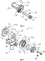
- FIG. 1 a possible embodiment of a joint body 20 is shown, in which a locking element 30 can be inserted.
- the joint body 20 has a joint body surface 21 which, together with a joint receiving surface 11, forms a hinge joint, which is pivotable about an axis of rotation 12. Accordingly, the hinge body surface is formed cylindrically with a circular cross section.
- the joint body surface 21 has a body locking structure 24, which in the in FIG. 1 shown embodiment is provided as a recess which extends into the joint body surface 21. As shown, the recess may extend across the entire width of the articulating body surface 21. However, it is also possible for the recess to extend only partially across the width of the articulated body surface 21.
- this can also be provided on the joint body 20 within the joint body surface 21 or on at least one end face of the joint body 20.
- the joint body 20 has at one end a securing portion 25, which is designed as a flange in the present embodiment. This provides, as already described above, a defined insertion depth of Hinge body 20 in a joint receptacle 10 (see FIG. 2 ) ready.
- locking member 30 allows for indirect locking of the body locking structure 24 and a receiving locking structure 14 of the hinge seat 10 (see FIG. 2 ). It is also possible to provide a direct locking between the body locking structure and the receiving locking structure. In such a case, the body locking structure and the receiving locking structure are complementary to each other, so that no locking member is necessary to cause a lock between the joint body 20 and the hinge seat 10.
- the locking element 30 is in the in FIG. 1 shown embodiment parallel to and at a distance from the axis of rotation 12 in the receptacle of the body locking structure 24 insertable.
- the recess of the body locking structure 24 is made complementary to the shape of the locking element 30. In the exemplary embodiment shown, it has a part-circular cross-section.
- the locking element 30 is inserted from the side into the body locking structure 24, on which the securing portion 25 of the joint body 20 is provided.
- the securing portion 25 designed as a flange has a through hole 27.
- the through-hole 27 is preferably formed with a thread into which a threaded portion 32 of the locking element 30 engages in order to secure the locking element 30 to the joint body 20. This backup prevents unintentional release of the lock.
- the threaded portion 32 preferably has a larger diameter than that of the body locking structure 24 via a form-fitting engageable locking portion 34 of the locking member 30. Furthermore, the locking member 30 at its insertion in the rear end behind the threaded portion 32, a head 33, in which an engagement of a tool, a tool engaging portion 35 is provided to screw the threaded portion 32 in the threaded through hole 27 of the joint body 20.
- the a hinge assembly 1 illustrative FIG. 2 shows that in FIG. 1 described locking element 30 in engagement with the body locking structure 24 of the joint body 20.
- the joint body 20 is inserted into a through hole 13 along the axis of rotation 12 of the joint. At least a part of the inner surface of the through hole 13 forms the hinge receiving surface 11, which is movable relative to the hinge body surface 21 of the joint body 20 in the assembled unlocked state.
- the hinge receiving surface 11 is interrupted by a recess which forms the receiving lock structure 14.
- This recess extends over the entire depth of the through hole 13.
- an embodiment of the recess is possible, which extends over only a part of the depth of the through hole 13.
- such an arrangement of the locking structures 14, 24 has the advantage of a very stable locking with little play.
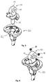
- the joint receptacle 10 on a connecting portion 16 which, as will be described in more detail below, for making a connection with a second joint component 60 is used (see FIGS. 3 and 4 ).
- a joint recording which is located on the tibial side of a knee joint replacement.
- FIG. 2 two adapter elements 40a, 40b shown, which are arranged on both sides of the through hole 13 of the joint seat 10. As related to the below FIGS. 5 and 6 is described, the adapter elements 40a, 40b are arranged or inserted laterally to the first joint component 50.
- the adapter elements 40a, 40b have detents 42 which prevent rotation about the axis of rotation 12 relative to the first hinge component 50.
- the adapter element 40b has on the side facing the securing portion 25 a stop surface 43 which contacts the securing portion 25 when the joint body 20 is inserted.
- this has a through hole 47 with a locking element recess 45.
- the locking element recess 45 is at least partially designed so that it receives a portion of the threaded portion 32 of the locking member 30, but preferably does not go into this with threaded engagement.
- the locking element recess 45 preferably narrows towards the side of the adapter element 40b opposite the abutment surfaces 43, as in the case of the second adapter element 40a in FIG. 2 recognizable, so that thereafter only the locking portion 34 of the locking element 30 can be inserted. It will be understood that the adapter element 40b may be implemented with a locking element recess 45 which is provided continuously only for receiving the locking section 34.
- a locking element recess 45 is preferably provided on the locking section 34 in the case of both adapter elements 40a, 40b
- embodiments are still conceivable in which only the adapter element 40b located on the side of the securing section 25 has a locking element recess 45.
- the locking section 34 is received in both adapter elements 40a, 40b, a more stable locking is possible because the locking element 30 can be supported on both sides by the joint receptacle 10.
- the adapter element 40b also has in the in FIG. 2 In the embodiment shown in the stop surface 43, a receptacle 46 for a fastening element 26.
- This receptacle 46 is preferably formed as a threaded hole.
- the fastening element 26 is inserted, which via a through hole 22 in the securing portion 25 of the joint body 20, the joint body 20 on the adapter element 40b guaranteed. In this way it can be ensured that in the unlocked state of the joint structure 1, a relative movement only between the joint receiving surface 11 and the joint body surface 21 is possible.
- this may be omitted in alternative embodiments.
- the locking member 30 is inserted into the through hole 27 of the joint body 20, the locking element recess 45 in the adapter member 40b, the receiving latch structure 14 and the locking element recess 45 of the adapter element 40a only when they assume a locking position in which they are aligned.
- the joint body 20 is connected directly to a first joint component 50 instead of the adapter element 40, accordingly at least the receiving locking structure 14 and the body locking structure 24 must be aligned with each other and using a locking element 30 corresponding to the recess in the first recess Joint component 50.
- the angle between the first hinge component 50 and the second hinge component 60 which the hinge assembly 1 provides in the locked state is, depending on the embodiment, a corresponding relative arrangement of the female latch structure 14, the body latch structure 24, the latch recess 45, and / or the detents 42 Rotation axis 12 to each other adjustable.
- an adjustment of this angle is most easily possible by a corresponding arrangement of the detents 42 on the adapter elements 40a and 40b. Consequently, by appropriate placement of the detents 42 on the adapter elements 40a and 40b different adapter elements may be provided for different locking angles.
- two or three receiving locking structures 14 are provided which, as described, are even more preferably designed as a recess in the joint receptacle 11.
- a surgeon may select a first limb-arranged female interlocking structure 14 or a second limb-arranged female interlocking structure 14. It is also conceivable to choose a locking position between an extension and a flexion of the joint, which may be advantageous for walking with a walking aid, for example.
- a centering means 28 can furthermore be provided which, when the locking position is reached, engages noticeably in a centering recess 19 of the joint receptacle 10.
- a centering pin is provided as centering means 28, which can engage in the securing portion 25 of the joint body 20 in a centering recess 19 through a centering through hole 29, which signals to an operator that the locking position has been reached is and thus the locking member 30 can be inserted.
- joint structure 1 In the following, the assembly of the joint structure 1 will now be described in more detail with reference to a knee joint replacement, but it can also be carried out on other joints, such as, for example, an elbow joint.
- second joint component 60 is a tibial component, which can be already implanted in a retrofit of the joint structure 1 in the fall of a retrofit in the knee of a patient or implant as a new implant.
- the connecting section of the joint receptacle 10 is inserted into a corresponding connecting section 62 of the second joint component 60.
- the assembly of the joint receptacle 10 takes place with the second joint component 60 via a positive connection and subsequent fixation with fasteners 18.
- other mounting options of the second joint component 60 with the hinge assembly 10 are conceivable, such as a cone connection.
- first joint component 50 already be implanted, so that a previously existing joint structure is replaced by the joint structure 10, or newly implanted together with the joint structure 10.
- the first joint component 50 shown is a femoral component of a knee joint.
- 10 adapter elements 40a, 40b are used in the context of the joint structure. Consequently, the hinge assembly 10, as described above, is a modular system that makes the hinge assembly of a can replace common Gelenkendoprothese with the locked joint structure 1 of the present invention.
- the adapter elements 40a, 40b are each inserted via an insertion projection 49 into corresponding through holes 59 of the first joint component 50.
- these through holes 59 may be provided for a hinge axis.
- the latches 42 of the adapter elements 40a, 40b are engaged with corresponding latches 52 of the first hinge component 50 upon insertion of the adapter elements 40a, 40b.
- each adapter element 40 has two detents 42 which cooperate with two detents 52 of the first hinge component to fix the respective adapter element 40 in the corresponding through hole 59 in the rotational direction.
- the locking position and thus the angle between the first joint component 50 and the second joint component can be determined by the choice of the adapter elements 40 by the latches are provided according to the circumference of the adapter elements.
- FIGS. 5 and 6 It can be seen from the locking element recess 45 and the receiving locking structure 14 positioned by the detents 42 and 52 that the exemplary knee joint replacement is in extension in the locked state. However, as discussed above, it may be advantageous to choose a different angle, such as an angle at which the patient can assume a sitting position.
- FIG. 6 shows the pre-assembled with the adapter elements 40a, 40b first joint component 50 and pre-assembled with the joint receiving 10 second joint component 60 prior to their positioning to each other.
- the first joint component 50 may have, in addition to the joint formed by the joint structure 1, a further joint surface 55 which, in the assembled state of the joint, interacts with a joint surface 65 mounted on the second joint component.
- first joint component 50 and the second joint component 60 are arranged relative to one another such that the through-hole 47 of the adapter elements 40a and 40b and the through-hole 13 of the joint receptacle 10 are aligned with one another.
- the hinge body 20 can be inserted via the through hole 47 of the first adapter member 40b, the through hole 13 of the hinge receiver 10, and the through hole 47 of the second adapter member 40a.
- first joint component 50 when the first joint component 50 is an already implanted joint component, bone tissue may be located in front of the through holes 59 of the first joint component 50. Accordingly, a passage to at least one of the through holes 59 must first be created intraoperatively. This is preferably done with a hollow milling machine, with which a bone cylinder with a diameter is taken laterally along the axis of rotation 12 of the joint, so that a free access to the at least one through hole 59 of the first joint component 50 is formed. After assembly, the removed bone cylinder can be used again to re-close the access to the respective through hole 59 created.
- the securing of the joint body takes place via a single securing section 25 designed as a flange. Consequently, access to one of the through-holes 59 is sufficient to retrofit the joint replacement with the joint structure 1. This has the advantage that the bone tissue and thus the patient are spared.
- FIG. 7 it can be seen that the joint body 20 can be used with already engaged locking element 30. It is understood that this is not necessary, but instead the locking element 30 is only used when a locking of the joint is desired or for a locking first the joint body 20 and then the locking member 30 is used.
- the hinge body 20 and the locking member 30 are used in this way, must in the embodiment shown in addition to the aforementioned through holes 47 and 13, the locking element recess 45 of at least one of the adapter elements 40a, 40b and the recess designed as a receiving locking structure 14 are aligned, ie are in the locked position.
- FIG. 8 Finally, Figure 1 shows the joint assembly 1 in a state mounted with the first joint component 50 and the second joint component 60. As can be seen, the hinge body 20 is secured to the first hinge component 50 via the securing portion 25 and the fastener 26. Consequently, in the embodiment shown in the joint structure 1, only a relative movement between the joint receiving surface 11 and the joint body surface 21 is possible.
- centering means can be removed.
- the centering means as described above as an aid to find the locking position, but instead to use it as additional securing elements against rotation of the joint body 20 relative to the first joint component 50.
Landscapes
- Health & Medical Sciences (AREA)
- Orthopedic Medicine & Surgery (AREA)
- Physical Education & Sports Medicine (AREA)
- Cardiology (AREA)
- Oral & Maxillofacial Surgery (AREA)
- Transplantation (AREA)
- Engineering & Computer Science (AREA)
- Biomedical Technology (AREA)
- Heart & Thoracic Surgery (AREA)
- Vascular Medicine (AREA)
- Life Sciences & Earth Sciences (AREA)
- Animal Behavior & Ethology (AREA)
- General Health & Medical Sciences (AREA)
- Public Health (AREA)
- Veterinary Medicine (AREA)
- Prostheses (AREA)
- Bridges Or Land Bridges (AREA)
Abstract
Description
- Die vorliegende Erfindung betrifft einen Gelenkaufbau für eine ein Scharniergelenk ausbildende Gelenkendoprothese sowie ein Verfahren zu dessen Verriegelung.
- Es kann notwendig oder von Vorteil sein, ein Gelenk im Rahmen einer Behandlung ruhig zu stellen. Indikationen hierfür, die eine solche Ruhigstellung eines Gelenks erfordern, sind zum Beispiel Entzündungen im Bereich des Gelenks, eine Schwächung oder Reizung des Bänderapparats, der das Gelenk umgibt, oder eine Fraktur des Knochengewebes.
- Eine Ruhigstellung eines Gelenks kann dabei auch im Zusammenhang mit einem künstlichen Gelenk von Vorteil sein, das bereits implantiert oder noch zu implantieren ist. Insbesondere bei einer Entzündung im Gelenkbereich, die beispielsweise durch ein abgenutztes natives Gelenk hervorgerufen werden kann, stellt sich zudem das Problem, dass entzündetes Gewebe entfernt werden muss, jedoch noch kein Gelenkersatz implantiert werden sollte, da dessen Beweglichkeit eine weitere Reizung des umliegenden Gewebes zur Folge hat.
- Aus diesem Grund wird anstelle eines vollständigen Gelenkersatzes beispielsweise zumindest zweitweise ein Arthrodesenagel implantiert, der das betroffene Gelenk blockiert, indem er es überbrückt. Sobald sich die gesundheitliche Situation des Patienten ausreichend gebessert hat, kann der Arthrodesenagel in einem erneuten Eingriff wieder entfernt werden und durch einen Gelenkersatz ersetzt werden. Hierfür muss der Arthrodesenagel wieder entfernt werden, was eine weitere Belastung des Patienten zur Folge hat. Insgesamt sind folglich zwei größere Eingriffe notwendig, um den Patienten zu behandeln.
- Ist bereits ein künstlicher Gelenkersatz implantiert, so kann eine Entzündung des umliegenden Knochen- oder Weichteilgewebes oder Abnutzung eine Revision dieses Gelenks notwendig machen. Die Revision eines Gelenks ist ebenfalls ein relativ starker Eingriff, der das Gewebe eines Patienten stark belastet und häufig mit einem erheblichen Verlust an Knochengewebe verbunden ist. Deswegen ist es unter Umständen von Vorteil, auch hier das Gelenk mittels eines Arthrodesenagels ruhig zu stellen. Die Folge sind wiederum die oben bereits beschriebenen zwei Eingriffe.
- Weiterhin kann nach einer Implantation eines künstlichen Gelenks oder nach dessen Revision zudem eine anfängliche Ruhigstellung des neuen künstlichen Gelenks die Heilung begünstigen, da sich der geschwächte Bänderapparat und das Knochengewebe von dem Eingriff erholen können. Auch kann es direkt nach einer Implantation eines künstlichen Gelenks zu kleineren Reizungen und Infekten kommen, die keine Revision notwendig machen, jedoch durch eine temporäre Ruhigstellung besser behandelt werden können. Hierfür gibt es derzeit nach Kenntnis der Erfinder keine praktikable Lösung, außer dem Patienten Bettruhe zu verordnen und damit dessen Bewegungsfreiheit entsprechend stark einzuschränken.
- Hiervon ausgehend war es eine Aufgabe der vorliegenden Erfindung, eine Möglichkeit bereitzustellen, welche eine möglichst schonende Ruhigstellung des Gelenkbereichs ermöglicht, ohne die Mobilität eines Patienten zu stark einschränken zu müssen.
- Die hierfür gefundene Lösung wird durch den Gelenkaufbau nach Anspruch 1 und die Verriegelung eines Gelenkaufbaus nach Anspruch 12 definiert. Die jeweiligen abhängigen Ansprüche definieren dabei bevorzugte Ausführungsformen des Gelenkaufbaus bzw. des Verriegelungsverfahrens.
- Der Gelenkaufbau der vorliegenden Erfindung für eine ein Scharniergelenk ausbildende Gelenkendoprothese weist dabei eine Gelenkaufnahme mit einer Gelenkaufnahmefläche und einer Aufnahmeverriegelungsstruktur sowie einen Gelenkkörper auf, der in der Gelenkaufnahme aufnehmbar ist und wiederum eine Gelenkkörperfläche und eine Körperverriegelungsstruktur aufweist. Die Gelenkaufnahmefläche und die Gelenkkörperfläche sind relativ zueinander in eine Stellung bewegbar, in der die Aufnahmeverriegelungsstruktur und die Körperverriegelungsstruktur eine Verriegelungsposition einnehmen, in der sie für einen verriegelten Zustand zwischen der Gelenkaufnahme und dem Gelenkkörper in Eingriff bringbar sind.
- Durch diesen Gelenkaufbau kann die Gelenkendoprothese ruhiggestellt werden und hat im verriegelten Zustand dementsprechend die Wirkung eines Arthrodesenagels. Damit wird der Drehung des Scharniergelenks vorgebeugt. Zudem kann durch ein Lösen der Verriegelung diese Blockade des Gelenkaufbaus und damit der Gelenkendoprothese wieder rückgängig gemacht werden. Als Ergebnis wird eine Reizung oder Entzündung des betroffenen Gelenks behandelt, ohne dass eine Revision der Gelenkendoprothese notwendig ist.
- Weiterhin hat der Gelenkaufbau insbesondere den Vorteil, dass eine Verriegelung des Scharniergelenks durch einen kleinen Einschnitt in das Gewebe des Patienten, der die Körperverriegelungsstruktur und die Aufnahmeverriegelungsstruktur zugänglich macht, möglich ist. Ein solcher minimalinvasiver Eingriff minimiert die Belastung des Patienten.
- Durch die Blockade des Gelenks wird zudem Schmerzen vorgebeugt, die anderweitig durch die normale Beweglichkeit des Gelenks hervorgerufen werden könnten. Damit ist ein Patient in der Lage, kurze Distanzen weiter selbst zurücklegen, ohne dabei Hilfe von außen zu benötigen.
- Bei dem Scharniergelenk bildet der Gelenkkörper die Achse des Scharniergelenks und die Gelenkaufnahme das Lager für diese Achse aus. Derartige Scharniergelenke treten bei Tieren und bei Menschen beispielsweise beim Kniegelenk oder beim Ellenbogengelenk auf. Dementsprechend ist die Verwendung des Begriffs Patienten nicht beschränkend auf Menschen auszulegen.
- Bei einer bevorzugten Ausführungsform grenzt die Aufnahmeverriegelungsstruktur an die Gelenkaufnahmefläche und die Körperverriegelungsstruktur an die Gelenkkörperfläche an.
- Eine derartige Anordnung der Aufnahmeverriegelungsstruktur und der Körperverriegelungsstruktur hat den Vorteil, dass die Verriegelung in unmittelbarer Nähe der Lauffläche des Scharniergelenks erfolgt und somit ein besonders geringes Spiel im verriegelten Zustand erreicht wird, da die Verriegelung dort stattfindet, wo das Gelenk über die Laufflächen seine Beweglichkeit erhält. Folglich wird der Bewegung des Gelenks genau dort vorgebeugt, wo diese entsteht. Durch das hierdurch ermöglichte geringere Spiel wird zudem einem möglichen Versagen der Verriegelung vorgebeugt.
- Bei einer weiteren besonders bevorzugten Ausführungsform ist die Aufnahmeverriegelungsstruktur als Aussparung in der Gelenkaufnahmefläche und/oder die Körperverriegelungsstruktur als Aussparung in der Gelenkkörperfläche ausgebildet.
- Auch bei dieser Ausführungsform wird eine Verriegelung an den Laufflächen des Gelenks mit wenig Spiel erreicht.
- Sind die Körperverriegelungsstruktur und die Aufnahmeverriegelungsstruktur komplementär zueinander ausgebildet, erfolgt eine Verriegelung durch einen direkten Formschluss zwischen den beiden Verriegelungsstrukturen.
- Bei einer weiteren Ausführungsform sind die Aufnahmeverriegelungsstruktur und die Körperverriegelungsstruktur mit einem Verriegelungselement in Eingriff bringbar, wobei das Verriegelungselement vorzugsweise in der Verriegelungsposition in die Aufnahmeverriegelungsstruktur und die Körperverriegelungsstruktur einführbar ist.
- Folglich werden bei dieser Ausführungsform die Aufnahmeverriegelungsstruktur und die Körperverriegelungsstruktur indirekt miteinander in Eingriff gebracht.
- Das Verriegelungselement hat den Vorteil, dass es nicht in dem Gelenkaufbau verbleibt, wenn keine Verriegelung des Gelenkaufbaus gewünscht ist. Mit anderen Worten handelt es sich um ein getrenntes Verriegelungselement. Damit wird zum einen die Konstruktion des Gelenkaufbaus vereinfacht und zum anderen der Möglichkeit vorgebeugt, dass das Verriegelungselement das Gelenk nicht unbeabsichtigt verriegelt. In dieser Ausführung ist das Verriegelungselement somit nicht nur lösbar sondern auch entfernbar ausgeführt. Auch hier reicht der zuvor bereits beschriebene kleine Einschnitt in Gelenknähe aus, um die Verriegelung auszuführen und wieder rückgängig zu machen.
- Weiterhin ist bei dieser Ausführungsform vorzugsweise sowohl die Aufnahmeverriegelungsstruktur als auch die Körperverriegelungsstruktur als Aussparung ausgebildet. Die beiden Aussparungen bilden in der Verriegelungsposition zusammen eine Verriegelungsaussparung aus. Mit anderen Worten fluchten die Aufnahmeverriegelungsstruktur und die Körperverriegelungsstruktur in der Verriegelungsposition miteinander, sodass ein Verriegelungselement einführbar ist. Die durch die Aufnahmeverriegelungsstruktur und die Körperverriegelungsstruktur ausgebildete Verriegelungsaussparung ist bevorzugt rotationssymmetrisch, noch bevorzugter zylindrisch und am bevorzugtesten kreisförmig zylindrisch. Weiterhin erstrecken sich die Aussparungen vorzugsweise in die jeweilige Fläche, sodass ein Verriegelungselement von außerhalb der Fläche eingeführt werden kann.
- Bei einer weiteren bevorzugten Ausführungsform sind die Gelenkaufnahme und der Gelenkkörper relativ zueinander um eine Rotationsachse schwenkbar und ist das Verriegelungselement im Wesentlichen parallel zu der Rotationsachse einführbar.
- Bei dieser Ausführungsform wird durch die Einführbarkeit des Verriegelungselements parallel zu der Rotationsachse des Scharniergelenks ein besonders einfacher Zugang zum Gelenk von lateral oder medial für eine Verriegelung oder Entriegelung des Gelenks von außen ermöglicht.
- Bei einer weiteren bevorzugten Ausführungsform weist der Gelenkkörper einen Sicherungsabschnitt für eine Sicherung des Gelenkkörpers an einer ersten Gelenkkomponente auf, wobei der Sicherungsabschnitt vorzugsweise als mindestens ein Flansch an einem Ende des Gelenkkörpers ausgebildet ist.
- Der Sicherungsabschnitt verhindert eine Trennung des Gelenkkörpers und der Gelenkaufnahme nach einer Montage und gewährleistet so eine einwandfreie Funktion des Gelenkaufbaus. Zudem kann der Sicherungsabschnitt so ausgeführt sein, dass er als Anschlag dient, der ein definiertes Einschieben bei der Montage des Gelenkaufbaus ermöglicht.
- Der Sicherungsabschnitt ist vorzugsweise als Flansch ausgeführt, der in Richtung der Rotationsachse an zumindest einem Ende des Gelenkkörpers angebracht ist. Vorzugsweise ist der Flansch einstückig mit dem Flansch verbunden. Eine Sicherung des Sicherungsabschnitts und damit des Gelenkkörpers kann folglich durch ein Anbringen des Sicherungsabschnitts an einer ersten Gelenkkomponente erfolgen.
- Es ist möglich, an dem Gelenkkörper in axialer Richtung beidseitig Flansche vorzusehen, die im montierten Zustand beidseitig von der Gelenkaufnahme einer Trennung des Gelenkkörpers von der Gelenkaufnahme vorbeugen. Dabei kann der Gelenkkörper im unverriegelten Zustand durch die beiden Flansche nur in axialer Richtung gesichert sein und sich um die Rotationsachse des Scharniergelenks und relativ zu der ersten Gelenkkomponente drehen.
- Bei einer besonders bevorzugten Ausführungsform ist der Sicherungsabschnitt mit einem Befestigungselement an der ersten Gelenkkomponente befestigt.
- Folglich erfolgt über mindestens ein Befestigungselement eine vollständige Sicherung des Gelenkkörpers an der ersten Gelenkkomponente, d.h. diese ist gegen ein axiales Herausrutschen sowie eine Drehung relativ zu der ersten Gelenkkomponente gesichert. Dementsprechend kann der Sicherungsabschnitt bei dieser Ausführungsform durch lediglich einen Flansch ausgebildet sein, was eine kompakte Bauweise des Gelenkaufbaus möglich macht.
- Die vollständige Sicherung über das Befestigungselement erfolgt dabei vorzugsweise außerhalb der Gelenkachse und kann am einfachsten über eine Gewindeverbindung ausgeführt werden.
- Bei einer weiteren besonders bevorzugten Ausführungsform ist mindestens ein Adapterelement zwischen dem Gelenkkörper und der ersten Gelenkkomponente vorgesehen, das eine Stützfläche zum Unterstützen der Gelenkkörperfläche aufweist.
- Die Verwendung eines Adapterelements zwischen dem Gelenkkörper und der ersten Gelenkkomponente ermöglicht das Nachrüsten einer bereits implantierten Gelenkendoprothese mit dem Gelenkaufbau. Dies hat den Vorteil, dass eine bereits implantierte Komponente der Gelenkendoprothese nicht aus dem Knochen entfernt werden muss und so den Patienten schont. Damit bildet der Gelenkaufbau eine sinnvolle Ergänzung für bestehende Gelenkimplantatsysteme und erweitert die Einsatzmöglichkeiten dieser.
- Im verriegelten Zustand wird bei einem mit einem Adapter versehenen Gelenkaufbau vorzugsweise einer relativen Drehung zwischen der Gelenkaufnahme und dem Adapter vorgebeugt.
- Bei einer weiteren Ausführungsform weist das Adapterelement eine Arretierung auf, die einer Drehung zwischen dem Adapterelement und der ersten Gelenkkomponente vorbeugt.
- Diese Arretierung beugt einer Drehung zwischen dem Adapterelement und der ersten Gelenkkomponente sowohl im unverriegelten Zustand als auch im verriegelten Zustand vor. Vorzugsweise ist die Arretierung in Form von zwei Anschlagflächen ausgebildet, die im montierten Zustand mit zwei Anschlagflächen der ersten Gelenkkomponente in Drehrichtung zusammenwirken. Folglich sorgt die Arretierung dafür, dass eine Verriegelung durchgehend zwischen der Gelenkaufnahme und der ersten Gelenkkomponente erfolgt.
- Über die Arretierung kann zudem über ihre entsprechende Anordnung der Verriegelungswinkel zwischen der Gelenkaufnahme und der ersten Gelenkkomponente gewählt werden. Beispielsweise kann es für einen Patienten von Vorteil sein, dass die Verriegelung im Falle eines Kniegelenks in einer Stellung des Gelenkaufbaus erfolgt, in welcher der Patient sitzt. Dies trifft insbesondere auf Patienten zu, die einen Rollstuhl verwenden.
- Bei einer weiteren besonders bevorzugten Ausführungsform ist das Verriegelungselement vorzugweise über einen Gewindeabschnitt relativ zu dem Gelenkkörper fixierbar.
- Über einen derartigen Gewindeabschnitt kann das Verriegelungselement relativ zu dem Gelenkaufbau gesichert werden, wenn es für eine Verriegelung des Scharniergelenks im eingeführten Zustand ist. Damit wird einem versehentlichen oder unbeabsichtigten Herausbewegen des Verriegelungselements vorgebeugt. Insbesondere bei einem Einführen des Verriegelungselements parallel zu der Rotationsachse des Scharniergelenks kann die Fixierung über den Gewindeabschnitt durch einfaches Einschrauben des Verriegelungselements in eine Gelenkkomponente, d. h. die Gelenkseite der Gelenkaufnahme oder des Gelenkkörpers, ein Adapterelement und/oder einen Sicherungsabschnitt erfolgen.
- Bei einer weiteren besonders bevorzugten Ausführungsform weist die Gelenkaufnahme einen Verbindungsabschnitt für eine Verbindung mit einer zweiten Gelenkkomponente auf.
- Bei dieser Ausführung wird der gleiche Vorteil erreicht, wie im Falle des oben beschriebenen Adapterelements. Genauer gesagt ist es bei dieser Ausführungsform möglich, den Gelenkaufbau bei einer zweiten Gelenkkomponente, die der ersten Gelenkkomponente funktionell gegenüberliegt, nachzurüsten. Auch hier kann somit auf eine Revision einer bereits implantierten Gelenkkomponente verzichtet werden.
- Bei einer weiteren besonders bevorzugten Ausführungsform weist der Gelenkaufbau eine weitere Aufnahmeverriegelungsstruktur und/oder eine weitere Körperverriegelungsstruktur auf, die angeordnet ist, um mindestens eine weitere Verriegelungsposition für eine Verriegelung des Gelenkaufbaus bereitzustellen.
- Bei dieser Ausführungsform ist es möglich, die Verriegelung des Gelenkaufbaus und damit des Gelenkersatzes in unterschiedlichen Winkelstellungen vorzunehmen. Folglich kann der Verriegelungswinkel an die jeweiligen Bedürfnisse des Patienten angepasst werden. So ist es beispielsweise nicht immer von Vorteil eine Verriegelung vorzunehmen, sodass das betreffende Körperglied in einem gestreckten Zustand ist, wie zum Beispiel bei der oben erwähnten Verwendung eines Rollstuhls.
- Besonders bevorzugt werden dabei zwei, drei oder vier Aufnahmeverriegelungs- oder Körperverriegelungsstrukturen vorgesehen, die mit nur einer der jeweils anderen Struktur in eine entsprechende Anzahl von Verriegelungspositionen bringbar sind.
- Weiterhin stellt die vorliegende Erfindung ein Verfahren zur Verriegelung eines Gelenkaufbaus für eine ein Scharniergelenk ausbildende Gelenkendoprothese bereit, wobei das Verfahren die folgenden Schritte umfasst. Bei einem Schritt erfolgt das Einführen eines Gelenkkörpers, der eine Gelenkkörperfläche und eine Körperverriegelungsstruktur aufweist, in eine Gelenkaufnahme, die eine Gelenkaufnahmefläche und eine Aufnahmeverriegelungsstruktur aufweist. Weiterhin sieht das Verfahren ein Bewegen der Gelenkkörperfläche und der Gelenkaufnahmefläche relativ zueinander vor, sodass die Körperverriegelungsstruktur und die Aufnahmeverriegelungsstruktur eine Verriegelungsposition einnehmen. Als Teil des Verfahrens erfolgt das Verriegeln des Gelenkkörpers und der Gelenkaufnahme in der Verriegelungsposition durch in Eingriff bringen der Körperverriegelungsstruktur und der Aufnahmeverriegelungsstruktur.
- Damit ermöglicht dieser Aufbau eine Verriegelung einer Gelenkendoprothese und macht somit die weit aufwändigere und für den Patienten stärker belastende Verwendung eines Arthrodesenagels überflüssig. Zudem ist die Verriegelung vorzugsweise lösbar vorgesehen, sodass nach Erreichen des Behandlungsziels, welches durch die Verriegelung bezweckt wird, die Verriegelung wieder rückgängig gemacht werden und der Patient die Gelenkendoprothese wieder als solche verwenden kann.
- Bei einer weiteren Ausführungsform des Verfahrens zur Montage eines Gelenkaufbaus erfolgt die Verriegelung zwischen der Körperverriegelungsstruktur und der Aufnahmeverriegelungsstruktur mit einem Verriegelungselement.
- Der Einsatz eines Verriegelungselements zum Verriegeln des Gelenkaufbaus hat insbesondere den oben beschriebenen Vorteil, dass für die Verriegelung lediglich ein minimalinvasiver Eingriff erforderlich ist. Wenn das Verriegelungselement zudem entfernbar ausgebildet ist, ermöglicht dies eine vollständige Entfernung desselben, wenn keine Verriegelung des Gelenkaufbaus mehr notwendig ist. Dabei erfolgt auch der Eingriff zum Entfernen des Verriegelungselements minimalinvasiv.
- Bei einer weiteren Ausführungsform des Verfahrens zur Montage eines Gelenkaufbaus wird der Gelenkkörper über ein Adapterelement mit einer ersten Gelenkkomponente verbunden.
- Ein derartiger modularer Aufbau des Gelenkaufbaus in Bezug auf eine erste Gelenkkomponente durch die Verwendung eines Adapterelements ermöglicht den oben bereits beschriebenen vorteilhaften Einsatz bei einer bereits implantierten ersten Gelenkkomponente. Zudem ist bei Verwendung einer lösbaren bzw. entfernbaren Verriegelung keine Entnahme des Gelenkaufbaus erforderlich, was ebenfalls die Belastung eines Patienten verringert.
- Bei einer besonders bevorzugten Ausführungsform weist das Adapterelement eine Stützfläche, die mit der Gelenkaufnahmefläche der Gelenkaufnahme in Kontakt gebracht wird, und eine Arretierung auf, die einer relativen Drehung zwischen dem Adapterelement und der ersten Gelenkkomponente vorbeugt.
- Folglich übernimmt das Adapterelement die Lagerung des Gelenkkörpers, während über die Arretierung einer relativen Drehung zwischen dem Adapterelement und der ersten Gelenkkomponente vorgebeugt wird und damit jegliche Drehung zwischen dem Gelenkkörper und der Gelenkaufnahme direkt auf die erste Gelenkkomponente übertragen wird.
- Bei einer weiteren Ausführungsform wird die Gelenkaufnahme an einer zweiten Gelenkkomponente befestigt.
- Wie oben bereits beschrieben kann hierdurch eine medizinisch nicht notwendige Revision der zweiten Gelenkkomponente durch einfaches Nachrüsten des Gelenkaufbaus verhindert werden.
- In den folgenden Figuren sind gleiche oder gleichwirkende Merkmale mit gleichen Bezugszeichen versehen. Dabei zeigen die Figuren eine mögliche Ausführungsform und die Montage eines Gelenkaufbaus. Von dieser ausgehend werden nachfolgend auch andere Ausführungsformen erläutert, die ebenfalls in den Schutzbereich der Ansprüche fallen. Insbesondere zeigt
-
Figur 1 einen Gelenkkörper mit einem einzuführenden Verriegelungselement, -
Figur 2 einen Gelenkaufbau mit einer Gelenkaufnahme und einem Gelenkkörper, -
Figur 3 den modularen Aufbau einer zweiten Gelenkkomponente und einer Gelenkaufnahme, -
Figur 4 das Befestigen der Gelenkaufnahme an der zweiten Gelenkkomponente, -
Figur 5 zwei in eine erste Gelenkkomponente einsetzbare Adapterelemente, -
Figur 6 eine in eine zweite Gelenkkomponente eingesetzte Gelenkaufnahme und eine erste mit dieser zu montierenden Gelenkkomponente, -
Figur 7 eine erste und eine zweite Gelenkkomponente, die für ein Einführen eines Gelenkkörpers und eines Verriegelungselements zueinander ausgerichtet sind, und -
Figur 8 eine Ausführungsform eines Gelenkaufbaus, der eine erste und eine zweite Gelenkkomponente miteinander verbindet. - In
Figur 1 ist eine mögliche Ausführungsform eines Gelenkkörpers 20 dargestellt, in den ein Verriegelungselement 30 einführbar ist. Der Gelenkkörper 20 weist eine Gelenkkörperfläche 21 auf, die zusammen mit einer Gelenkaufnahmefläche 11 ein Scharniergelenk ausbildet, das um eine Rotationsachse 12 schwenkbar ist. Dementsprechend ist die Gelenkkörperfläche zylindrisch mit einem kreisförmigen Querschnitt ausgebildet. - Die Gelenkkörperfläche 21 weist eine Körperverriegelungsstruktur 24 auf, die bei dem in
Figur 1 gezeigten Ausführungsbeispiel als Aussparung vorgesehen ist, die sich in die Gelenkkörperfläche 21 erstreckt. Wie gezeigt, kann sich die Aussparung über die gesamte Breite der Gelenkkörperfläche 21 erstrecken. Allerdings ist es auch möglich, dass sich die Aussparung nur teilweise über die Breite der Gelenkkörperfläche 21 erstreckt. - Bei einer anderen Ausführung der Körperverriegelungsstruktur 24 kann diese an dem Gelenkkörper 20 auch innerhalb der Gelenkkörperfläche 21 oder an mindestens einer Stirnfläche des Gelenkkörpers 20 vorgesehen sein.
- In der
Figur 1 weist der Gelenkkörper 20 an einem Ende einen Sicherungsabschnitt 25 auf, der bei dem vorliegenden Ausführungsbeispiel als Flansch ausgeführt ist. Dieser stellt, wie oben bereits beschrieben, eine definierte Einführtiefe des Gelenkkörpers 20 in eine Gelenkaufnahme 10 (sieheFigur 2 ) bereit. - Das ebenfalls in
Figur 1 veranschaulichte Verriegelungselement 30 ermöglicht eine indirekte Verriegelung der Körperverriegelungsstruktur 24 und einer Aufnahmeverriegelungsstruktur 14 der Gelenkaufnahme 10 (sieheFigur 2 ). Ebenso ist es möglich, eine direkte Verriegelung zwischen der Körperverriegelungsstruktur und der Aufnahmeverriegelungsstruktur vorzusehen. In so einem Fall sind die Körperverriegelungsstruktur und die Aufnahmeverriegelungsstruktur komplementär zueinander ausgeführt, sodass kein Verriegelungselement notwendig ist, um eine Verriegelung zwischen dem Gelenkkörper 20 und der Gelenkaufnahme 10 hervorzurufen. - Das Verriegelungselement 30 ist in der in
Figur 1 gezeigten Ausführungsform parallel zu und in einem Abstand von der Rotationsachse 12 in die Aufnahme der Körperverriegelungsstruktur 24 einführbar. Die Aussparung der Körperverriegelungsstruktur 24 ist komplementär zu der Form des Verriegelungselement 30 ausgeführt. In der gezeigten beispielhaften Ausführungsform weist sie einen teilkreisförmigen Querschnitt auf. - Weiterhin ist das Verriegelungselement 30 von der Seite aus in die Körperverriegelungsstruktur 24 einführbar, auf welcher der Sicherungsabschnitt 25 des Gelenkkörpers 20 vorgesehen ist. Hierfür weist der als Flansch ausgebildete Sicherungsabschnitt 25 ein Durchgangsloch 27 auf. Das Durchgangsloch 27 ist vorzugsweise mit einem Gewinde ausgebildet, in das ein Gewindeabschnitt 32 des Verriegelungselements 30 eingreift, um das Verriegelungselement 30 an dem Gelenkkörper 20 zu sichern. Durch diese Sicherung wird ein unbeabsichtigtes Lösen der Verriegelung verhindert.
- Der Gewindeabschnitt 32 weist vorzugsweise einen größeren Durchmesser auf als der mit der Körperverriegelungsstruktur 24 über einen Formschluss in Eingriff bringbare Verriegelungsabschnitt 34 des Verriegelungselements 30. Weiterhin weist das Verriegelungselement 30 an seinem in Einführrichtung hinteren Ende hinter dem Gewindeabschnitt 32 einen Kopf 33 auf, in dem für einen Eingriff eines Werkzeugs ein Werkzeugeingriffsabschnitt 35 vorgesehen ist, um den Gewindeabschnitt 32 in das mit einem Gewinde vorgesehene Durchgangsloch 27 des Gelenkkörpers 20 zu schrauben.
- Die einen Gelenkaufbau 1 veranschaulichende
Figur 2 zeigt das inFigur 1 beschriebene Verriegelungselement 30 im Eingriff mit der Körperverriegelungsstruktur 24 des Gelenkkörpers 20. Wie derFigur 2 zu entnehmen ist, ist der Gelenkkörper 20 in ein Durchgangsloch 13 entlang der Rotationsachse 12 des Gelenks einführbar. Zumindest ein Teil der Innenfläche des Durchgangslochs 13 bildet die Gelenkaufnahmefläche 11 aus, die im montierten unverriegelten Zustand relativ zu der Gelenkkörperfläche 21 des Gelenkkörpers 20 bewegbar ist. - Bei der in
Figur 2 veranschaulichten Ausführungsform wird die Gelenkaufnahmefläche 11 durch eine Aussparung unterbrochen, welche die Aufnahmeverriegelungsstruktur 14 ausbildet. Diese Aussparung erstreckt sich über die gesamte Tiefe des Durchgangslochs 13. Wie bereits im Zusammenhang mit der Körperverriegelungsstruktur 24 beschrieben, ist allerdings ebenso eine Ausführung der Aussparung möglich, die sich nur über einen Teil der Tiefe des Durchgangslochs 13 erstreckt. Wie oben bereits ausgeführt, hat ein solches Anordnen der Verriegelungsstrukturen 14, 24 den Vorteil einer sehr stabilen Verriegelung mit wenig Spiel. - Wenn der Gelenkkörper 20 somit in die Gelenkaufnahme 10 eingeführt ist, ermöglicht das Verriegelungselement 30, welches im eingeführten Zustand sowohl mit der Körperverriegelungsstruktur 24 als auch mit der Aufnahmeverriegelungsstruktur 14 in Eingriff ist, eine Verriegelung des Scharniergelenks, die gegen eine Relativbewegung zwischen dem Gelenkkörper 20 und der Gelenkaufnahme 10 vorbeugt. Bei gelöstem bzw. entferntem Verriegelungselement 30 ist hingegen eine Relativbewegung zwischen dem Gelenkkörper 20 und der Gelenkaufnahme 10 möglich, sodass der Gelenkaufbau eine normale Funktion der Gelenkendoprothese ermöglicht.
- Wie weiter der
Figur 2 zu entnehmen ist, weist die Gelenkaufnahme 10 einen Verbindungsabschnitt 16 auf, der, wie weiter unten noch näher beschrieben wird, für das Herstellen einer Verbindung mit einer zweiten Gelenkkomponente 60 dient (sieheFiguren 3 und 4 ). Bei der inFigur 2 gezeigten beispielhaften Ausführungsform der Gelenkaufnahme 10 handelt es sich um eine Gelenkaufnahme, die sich auf der tibialen Seite eines Kniegelenkersatzes befindet. - Weiterhin sind in
Figur 2 zwei Adapterelemente 40a, 40b dargestellt, die beidseitig von dem Durchgangsloch 13 der Gelenkaufnahme 10 angeordnet sind. Wie weiter unten im Zusammenhang mit denFiguren 5 und 6 beschrieben wird, sind die Adapterelemente 40a, 40b seitlich zu der ersten Gelenkkomponente 50 angeordnet oder eingesetzt. - Die Adapterelemente 40a, 40b weisen Arretierungen 42 auf, die einer Drehung um die Rotationsachse 12 relativ zu der ersten Gelenkkomponente 50 vorbeugen. Alternativ zu den nachfolgend weiter im Detail beschriebenen Adapterelementen ist es auch möglich, eine erste Gelenkkomponente 50 vorzusehen, die ohne Adapterelement ein in diese intergriertes Durchgangsloch 47 mit Verriegelungselementaussparung 45 aufweist.
- Das Adapterelement 40b weist auf der dem Sicherungsabschnitt 25 zugewandten Seite eine Anschlagfläche 43 auf, die bei eingeführtem Gelenkkörper 20 den Sicherungsabschnitt 25 berührt.
- Wie bei der gezeigten Ausführungsform des Adapterelements 40b erkennbar, weist dieses ein Durchgangsloch 47 mit einer Verriegelungselementaussparung 45 auf. Die Verriegelungselementaussparung 45 ist dabei zumindest abschnittsweise so ausgeführt, dass sie einen Teil des Gewindeabschnitts 32 von dem Verriegelungselement 30 aufnimmt, jedoch bevorzugt nicht mit diesem in Gewindeeingriff geht.
- Die Verriegelungselementaussparung 45 verengt sich vorzugsweise zu der der Anschlagflächen 43 gegenüberliegenden Seite des Adapterelements 40b hin, wie bei dem zweiten Adapterelement 40a in
Figur 2 erkennbar, sodass danach lediglich der Verriegelungsabschnitt 34 des Verriegelungselements 30 einführbar ist. Es ist verständlich, dass das Adapterelement 40b mit einer Verriegelungselementaussparung 45 ausgeführt sein kann, die durchgehend nur für die Aufnahme des Verriegelungsabschnitts 34 vorgesehen ist. - Auch wenn bevorzugt bei beiden Adapterelementen 40a, 40b eine Verriegelungselementaussparung 45 den Verriegelungsabschnitt 34 vorgesehen ist, so sind dennoch Ausführungsformen denkbar, bei denen nur das auf der Seite des Sicherungsabschnitts 25 befindliche Adapterelement 40b eine Verriegelungselementaussparung 45 aufweist. Jedoch ist bei einer Aufnahme des Verriegelungsabschnitts 34 in beiden Adapterelementen 40a, 40b eine stabilere Verriegelung möglich, da sich das Verriegelungselement 30 beidseitig von der Gelenkaufnahme 10 abstützen kann.
- Das Adapterelement 40b weist zudem bei der in
Figur 2 gezeigten Ausführungsform in der Anschlagfläche 43 eine Aufnahme 46 für ein Befestigungselement 26 auf. Diese Aufnahme 46 ist bevorzugt als Gewindeloch ausgebildet. In die Aufnahme 46 ist das Befestigungselement 26 einführbar, das über ein Durchgangsloch 22 in dem Sicherungsabschnitt 25 des Gelenkkörpers 20 den Gelenkkörper 20 an dem Adapterelement 40b sichert. Hierdurch kann gewährleistet werden, dass im unverriegelten Zustand des Gelenkaufbaus 1 eine Relativbewegung nur zwischen der Gelenkaufnahmefläche 11 und der Gelenkkörperfläche 21 möglich ist. - Wie oben beschrieben, kann hierauf bei alternativen Ausführungsformen verzichtet werden. Beispielsweise ist es möglich, den Gelenkkörper an beiden Enden über als Flansche ausgebildete Sicherungsabschnitte 25 in dem Durchgangsloch 13 der Gelenkaufnahme 10 und dem Durchgangsloch 47 der Adapterelemente 40 zu sichern.
- Wie weiterhin in der
Figur 2 zu erkennen, ist das Verriegelungselement 30 nur dann in das Durchgangsloch 27 des Gelenkkörpers 20, die Verriegelungselementaussparung 45 in dem Adapterelement 40b, die Aufnahmeverriegelungsstruktur 14 und die Verriegelungselementaussparung 45 des Adapterelements 40a einführbar, wenn diese eine Verriegelungsposition einnehmen, in der sie zueinander fluchten. - Für den Fall, dass der Gelenkkörper 20 anstatt über das Adapterelement 40 direkt mit einer ersten Gelenkkomponente 50 verbunden ist, müssen dementsprechend zumindest die Aufnahmeverriegelungsstruktur 14 und die Körperverriegelungsstruktur 24 miteinander fluchten und bei Verwendung eines Verriegelungselements 30 entsprechend die der Verriegelungselementaussparung 45 entsprechende Aussparung in der ersten Gelenkkomponente 50.
- Der Winkel zwischen der ersten Gelenkkomponente 50 und der zweiten Gelenkkomponente 60, den der Gelenkaufbau 1 im verriegelten Zustand bereitstellt, ist je nach Ausführungsform durch eine entsprechende relative Anordnung der Aufnahmeverriegelungsstruktur 14, der Körperverriegelungsstruktur 24, der Verriegelungselementaussparung 45 und/oder der Arretierungen 42 um die Rotationsachse 12 zueinander einstellbar.
- Bei der dargestellten Ausführungsform ist eine Einstellung dieses Winkels am einfachsten durch eine entsprechende Anordnung der Arretierungen 42 an den Adapterelementen 40a und 40b möglich. Folglich können durch eine entsprechende Platzierung der Arretierungen 42 an den Adapterelementen 40a und 40b unterschiedliche Adapterelemente für unterschiedliche Verriegelungswinkel vorgesehen sein.
- Bei einer anderen oder ergänzenden Ausführung ist es möglich, wie oben bereits beschrieben, mehrere Aufnahmeverriegelungsstrukturen 14 und/oder Körperverriegelungsstrukturen 24 vorzusehen, um für die Verriegelung mehrere Verriegelungswinkel für die Gelenkendoprothese 90 zur Verfügung zu haben.
- Besonders bevorzugt werden zwei oder drei Aufnahmeverriegelungsstrukturen 14 vorgesehen, die, wie beschrieben, noch bevorzugter als Aussparung in der Gelenkaufnahme 11 ausgebildet sind. Beispielsweise kann ein Operateur je nach Patient eine erste für eine Extension der Gliedmaße angeordnete Aufnahmeverriegelungsstruktur 14 oder eine zweite für eine Beugung der Gliedmaße angeordnete Aufnahmeverriegelungsstruktur 14 auswählen. Es ist auch denkbar eine Verriegelungsposition zwischen einer Extension und einer Beugung des Gelenks zu wählen, die beispielsweise für ein Gehen mit einer Gehhilfe von Vorteil sein kann.
- Um intraoperativ durch eine Relativbewegung zwischen der Gelenkaufnahmefläche 11 und der Gelenkkörperfläche 21 die Verriegelungsposition leichter zu finden, kann weiterhin ein Zentriermittel 28 vorgesehen sein, dass bei Erreichen der Verriegelungsposition spürbar in eine Zentrieraussparung 19 der Gelenkaufnahme 10 eingreift. Bei der in
Figur 2 gezeigten Ausführungsform wird als Zentriermittel 28 ein Zentrierstift vorgesehen, der durch ein Zentrierdurchgangsloch 29 in dem Sicherungsabschnitt 25 des Gelenkkörpers 20 in einer Zentrieraussparung 19 einrasten kann, was einem Operateur signalisiert, dass die Verriegelungsposition erreicht worden ist und somit das Verriegelungselement 30 eingeführt werden kann. - Im Folgenden wird nunmehr die Montage des Gelenkaufbaus 1 näher anhand eines Kniegelenkersatzes beschrieben, ist aber ebenso an anderen Gelenken durchführbar, wie zum Beispiel einem Ellenbogengelenk.
- Die in
Figur 3 dargestellte zweite Gelenkkomponente 60 ist eine Tibiakomponente, die bei einer Nachrüstung des Gelenkaufbaus 1 im Fallen einer Nachrüstung bereits in dem Knie eines Patienten implantiert sein kann oder als neues Implantat zu implantieren ist. Für eine Montage des Gelenkaufbaus wird in einem Schritt nach Öffnung des Kniegelenks der Verbindungsabschnitt der Gelenkaufnahme 10 in einen korrespondierenden Verbindungsabschnitt 62 der zweiten Gelenkkomponente 60 eingesetzt. Wie in denFiguren 3 und 4 zu erkennen, erfolgt die Montage der Gelenkaufnahme 10 mit der zweiten Gelenkkomponente 60 über einen Formschluss und anschließender Fixierung mit Befestigungselementen 18. Alternativ sind auch andere Befestigungsmöglichkeiten der zweiten Gelenkkomponente 60 mit dem Gelenkaufbau 10 denkbar, wie zum Beispiel eine Konusverbindung. - Wie für die zweite Gelenkkomponente 60 beschrieben, kann auch die in den
Figuren 5 und 6 gezeigte erste Gelenkkomponente 50 bereits implantiert sein, sodass ein zuvor vorhandener Gelenkaufbau durch den Gelenkaufbau 10 ausgetauscht wird, oder neu zusammen mit dem Gelenkaufbau 10 implantiert werden. - Bei der in der beispielhaften Ausführungsform in
Figur 5 gezeigten ersten Gelenkkomponente 50 handelt es sich um eine Femurkomponente eines Kniegelenks. Zudem werden im Rahmen des Gelenkaufbaus 10 Adapterelemente 40a, 40b eingesetzt. Folglich handelt es sich bei dem Gelenkaufbau 10, wie oben beschrieben, um ein modulares Systems, das den Gelenkaufbau einer gewöhnlichen Gelenkendoprothese mit dem verriegelten Gelenkaufbau 1 der vorliegenden Erfindung ersetzen kann. - Im vorliegenden Fall werden die Adapterelemente 40a, 40b jeweils über einen Einsetzvorsprung 49 in entsprechende Durchgangslöcher 59 der ersten Gelenkkomponente 50 eingesetzt. Bei Verwendung der ersten Gelenkkomponente 50 mit einem gewöhnlichen nicht verriegelbaren Gelenkaufbau können diese Durchgangslöcher 59 für eine Gelenkachse vorgesehen sein. Die Arretierungen 42 der Adapterelemente 40a, 40b werden beim Einsetzen der Adapterelemente 40a, 40b mit entsprechenden Arretierungen 52 der ersten Gelenkkomponente 50 in Eingriff gebracht. Wie in
Figur 5 zu erkennen ist, weist jedes Adapterelement 40 zwei Arretierungen 42 auf, die mit zwei Arretierungen 52 der ersten Gelenkkomponente zusammenwirken, um das jeweilige Adapterelement 40 in dem entsprechenden Durchgangsloch 59 in Rotationsrichtung zu fixieren. - Vorzugsweise kann über die Wahl der Adapterelemente 40 die Verriegelungsposition und damit der Winkel zwischen der ersten Gelenkkomponente 50 und der zweiten Gelenkkomponente festgelegt werden, indem die Arretierungen entsprechend am Umfang der Adapterelemente vorgesehen werden.
- Wie den
Figuren 5 und 6 anhand der durch die Arretierungen 42 und 52 positionierte Verriegelungselementaussparung 45 und der Aufnahmeverriegelungsstruktur 14 erkennbar, befindet sich der beispielhafte Kniegelenkersatz im verriegelten Zustand in Extension. Wie oben bereits erläutert, kann es jedoch von Vorteil sein, einen anderen Winkel zu wählen, wie zum Beispiel einen Winkel, mit dem der Patient eine Sitzstellung einnehmen kann. -
Figur 6 zeigt die mit den Adapterelementen 40a, 40b vormontierte erste Gelenkkomponente 50 und die mit der Gelenkaufnahme 10 vormontierte zweite Gelenkkomponente 60 vor deren Positionierung zueinander. Wie inFigur 6 zu erkennen, kann die erste Gelenkkomponente 50 neben dem durch den Gelenkaufbau 1 ausgebildeten Gelenk eine weitere Gelenkfläche 55 aufweisen, die im montierten Zustand des Gelenks mit einer an der zweiten Gelenkkomponente montierten Gelenkfläche 65 zusammenwirkt. - In
Figur 7 sind die erste Gelenkkomponente 50 und die zweite Gelenkkomponente 60 so zueinander angeordnet, dass das Durchgangsloch 47 der Adapterelemente 40a und 40b und das Durchgangsloch 13 der Gelenkaufnahme 10 zueinander fluchten. Folglich kann in diesem Zustand der Gelenkkörper 20 über das Durchgangsloch 47 des ersten Adapterelements 40b, das Durchgangsloch 13 der Gelenkaufnahme 10 und das Durchgangsloch 47 des zweiten Adapterelements 40a eingeführt werden. - In diesem Zusammenhang ist anzumerken, dass wenn es sich bei der ersten Gelenkkomponente 50 um eine bereits implantierte Gelenkkomponente handelt, sich vor den Durchgangslöchern 59 der ersten Gelenkkomponente 50 Knochengewebe befinden kann. Dementsprechend muss intraoperativ zunächst ein Durchgang zu zumindest einem der Durchgangslöcher 59 geschaffen werden. Dies erfolgt vorzugsweise mit einer Hohlfräse, mit der ein Knochenzylinder mit einem Durchmesser seitlich entlang der Rotationsachse 12 des Gelenks entnommen wird, sodass ein freier Zugang zu dem mindestens einen Durchgangsloch 59 der ersten Gelenkkomponente 50 entsteht. Nach der Montage kann der entnommene Knochenzylinder wieder eingesetzt werden, um den erzeugten Zugang zu dem jeweiligen Durchgangsloch 59 wieder zu verschließen.
- Bei der in den Figuren gezeigten Ausführungsform erfolgt die Sicherung des Gelenkkörpers über einen einzigen als Flansch ausgeführten Sicherungsabschnitt 25. Folglich reicht ein Zugang zu einem der Durchgangslöcher 59, um den Gelenkersatz mit dem Gelenkaufbau 1 nachzurüsten. Dies hat den Vorteil, dass das Knochengewebe und damit der Patient geschont werden.
- Weiterhin ist der
Figur 7 zu entnehmen, dass der Gelenkkörper 20 mit bereits einem in Eingriff befindlichen Verriegelungselement 30 eingesetzt werden kann. Es ist verständlich, dass dies nicht notwendig ist, sondern stattdessen das Verriegelungselement 30 erst dann eingesetzt wird, wenn eine Verriegelung des Gelenks gewünscht ist oder auch für eine Verriegelung erst der Gelenkkörper 20 und dann das Verriegelungselement 30 eingesetzt wird. - Wenn, wie in
Figur 7 gezeigt, der Gelenkkörper 20 und das Verriegelungselement 30 auf diese Weise eingesetzt werden, müssen bei der gezeigten Ausführungsform dementsprechend neben den vorgenannten Durchgangslöchern 47 und 13 auch die Verriegelungselementaussparung 45 von zumindest einem der Adapterelemente 40a, 40b sowie die als Aussparung ausgeführte Aufnahmeverriegelungsstruktur 14 fluchten, d. h. sich in der Verriegelungsposition befinden. -
Figur 8 zeigt schließlich den Gelenkaufbau 1 in einem mit der ersten Gelenkkomponente 50 und der zweiten Gelenkkomponente 60 montierten Zustand. Wie zu erkennen ist, ist der Gelenkkörper 20 über den Sicherungsabschnitt 25 und das Befestigungselement 26 an der ersten Gelenkkomponente 50 gesichert. Folglich ist bei der gezeigten Ausführungsform in dem Gelenkaufbau 1 lediglich eine Relativbewegung zwischen der Gelenkaufnahmefläche 11 und der Gelenkkörperfläche 21 möglich. - Dies hat unter anderem den Vorteil, dass das durch den Gelenkaufbau 1 ausgebildete Gelenk von der Knochenseite her abgeschlossen ist, sodass einem Eindringen von Fremdpartikeln in das Gelenk vorgebeugt wird. Als Ergänzung ist es möglich, statt eines Durchgangsloch 47 bei dem Adapterelement 40a, das dem Adapterelement 40b gegenüberliegt, an dem der Sicherungsabschnitt 25 des Gelenkkörpers 20 anliegt, ein Sackloch vorzusehen oder auch eine Kappe, wieder Durchgangsloch 47 des Adapterelements 40a bedeckt. Damit wird auch einem Eindringen von Fremdpartikeln von der anderen Seite des Gelenkaufbaus 1 aus vorgebeugt.
- Weiterhin wird in der
Figur 8 dargestellt, dass die Zentriermittel entnommen werden können. Alternativ oder ergänzend ist es möglich, die Zentriermittel nicht wie zuvor beschrieben als Hilfsmittel einzusetzen, um die Verriegelungsposition zu finden, sondern diese stattdessen als zusätzliche Sicherungselemente gegen ein Verdrehen des Gelenkkörpers 20 relativ zu der ersten Gelenkkomponente 50 einzusetzen. -
- 1
- Gelenkaufbau
- 10
- Gelenkaufnahme
- 11
- Gelenkaufnahmefläche
- 12
- Rotationsmittelpunkt
- 13
- Durchgangsloch
- 14
- Aufnahmeverriegelungsstruktur
- 16
- Verbindungsabschnitt
- 18
- Befestigungselement
- 19
- Zentrieraussparung
- 20
- Gelenkkörper
- 21
- Gelenkkörperfläche
- 22
- Durchgangsloch für das Befestigungselement 26
- 24
- Körperverriegelungsstruktur
- 25
- Sicherungsabschnitt
- 26
- Befestigungselement
- 27
- Durchgangsloch
- 28
- Zentriermittel
- 29
- Zentrierdurchgangsloch
- 30
- Verriegelungselement
- 32
- Gewindeabschnitt des Verriegelungselements
- 33
- Kopf des Verriegelungselements
- 34
- Verriegelungsabschnitt
- 40a,b
- Adapterelement
- 41
- Stützfläche für Gelenkkörper
- 42
- Arretierung
- 43
- Anschlagfläche
- 44
- Stützfläche für Verriegelungselement
- 45
- Verriegelungselementaussparung
- 46
- Aufnahme für das Befestigungselement 26
- 47
- Durchgangsloch zur Aufnahme des Gelenkkörpers
- 48
- Aufnahme für das Zentriermittel 28
- 49
- Einsetzvorsprung
- 50
- erste Gelenkkomponente
- 52
- Arretierung
- 55
- Gelenkfläche der ersten Gelenkkomponente
- 59
- Durchgangsloch der ersten Gelenkkomponente
- 60
- zweite Gelenkkomponente
- 62
- Verbindungsabschnitt
- 65
- Gelenkfläche der zweiten Gelenkkomponente
- 70
- dritte Gelenkkomponente
- 80
- vierte Gelenkkomponente
- 90
- Gelenkendoprothese
Claims (16)
- Gelenkaufbau (1) für eine ein Scharniergelenk ausbildende Gelenkendoprothese (90), der aufweist:- eine Gelenkaufnahme (10), die eine Gelenkaufnahmefläche (11) und eine Aufnahmeverriegelungsstruktur (14) aufweist,- einen Gelenkkörper (20), der in der Gelenkaufnahme (10) aufnehmbar ist und eine Gelenkkörperfläche (21) und eine Körperverriegelungsstruktur (24) aufweist,wobei die Gelenkaufnahmefläche (11) und die Gelenkkörperfläche (21) relativ zueinander in eine Stellung bewegbar sind, in der die Aufnahmeverriegelungsstruktur (14) und die Körperverriegelungsstruktur (24) eine Verriegelungsposition einnehmen, in der sie für einen verriegelten Zustand zwischen der Gelenkaufnahme (10) und dem Gelenkkörper (20) in Eingriff bringbar sind.
- Gelenkaufbau nach Anspruch 1, bei dem die Aufnahmeverriegelungsstruktur (14) an die Gelenkaufnahmefläche (11) und die Körperverriegelungsstruktur (24) an die Gelenkkörperfläche (21) angrenzt.
- Gelenkaufbau nach Anspruch 1 oder 2, bei dem die Aufnahmeverriegelungsstruktur (14) als Aussparung in der Gelenkaufnahmefläche (11) und/oder die Körperverriegelungsstruktur (24) als Aussparung in der Gelenkkörperfläche (21) ausgebildet ist.
- Gelenkaufbau nach einem der vorstehenden Ansprüche, bei dem die Aufnahmeverriegelungsstruktur (14) und die Körperverriegelungsstruktur (24) mit einem Verriegelungselement (30) in Eingriff bringbar sind, wobei das Verriegelungselement (30) vorzugsweise in der Verriegelungsposition in die Aufnahmeverriegelungsstruktur (14) und die Körperverriegelungsstruktur (24) einführbar ist.
- Gelenkaufbau nach Anspruch 4, bei dem die Gelenkaufnahme (10) und der Gelenkkörper (20) relativ zueinander um eine Rotationsachse (12) schwenkbar sind und das Verriegelungselement (30) im Wesentlichen parallel zu der Rotationsachse (12) einführbar ist.
- Gelenkaufbau nach einem der vorstehenden Ansprüche, bei dem der Gelenkkörper (20) einen Sicherungsabschnitt (25) für eine Sicherung des Gelenkkörpers (20) an einer ersten Gelenkkomponente (50) aufweist, wobei der Sicherungsabschnitt (25) vorzugsweise als Flansch an einem Ende des Gelenkkörpers (20) ausgebildet ist.
- Gelenkaufbau nach Anspruch 6, bei dem der Sicherungsabschnitt (25) mit einem Befestigungselement (26) an der ersten Gelenkkomponente (50) befestigt ist.
- Gelenkaufbau nach Anspruch 6 oder 7, bei dem mindestens ein Adapterelement (40) zwischen dem Gelenkkörper (20) und der ersten Gelenkkomponente (50) vorgesehen ist, das eine Stützfläche (41) zum Unterstützen der Gelenkkörperfläche (21) aufweist.
- Gelenkaufbau nach Anspruch 8, bei dem das Adapterelement (40) eine Arretierung (42) aufweist, die einer Drehung zwischen dem Adapterelement (40) und der ersten Gelenkkomponente (50) vorbeugt.
- Gelenkaufbau nach einem der Ansprüche 4 bis 9, bei dem das Verriegelungselement (30) vorzugweise über einen Gewindeabschnitt (32) relativ zu dem Gelenkkörper (20) fixierbar ist.
- Gelenkaufbau nach einem der vorstehenden Ansprüche, bei dem die Gelenkaufnahme (10) einen Verbindungsabschnitt (16) für eine Verbindung mit einer zweiten Gelenkkomponente (60) aufweist.
- Gelenkaufbau nach einem der vorstehenden Ansprüche, der mindestens eine weitere Aufnahmeverriegelungsstruktur (14) und/oder eine weitere Körperverriegelungsstruktur (24) aufweist, die angeordnet ist, um mindestens eine weitere Verriegelungsposition für eine Verriegelung des Gelenkaufbaus bereitzustellen.
- Verfahren zur Verriegelung eines Gelenkaufbaus (1) für eine ein Scharniergelenk ausbildende Gelenkendoprothese (90), wobei das Verfahren die Schritte umfasst:- Einführen eines Gelenkkörpers (20), der eine Gelenkkörperfläche (21) und eine Körperverriegelungsstruktur (24) aufweist, in eine Gelenkaufnahme (10), die eine Gelenkaufnahmefläche (11) und eine Aufnahmeverriegelungsstruktur (14) aufweist;- Bewegen der Gelenkkörperfläche (21) und der Gelenkaufnahmefläche (11) relativ zueinander, sodass die Körperverriegelungsstruktur (24) und die Aufnahmeverriegelungsstruktur (14) eine Verriegelungsposition einnehmen;- Verriegeln des Gelenkkörpers (20) und der Gelenkaufnahme (10) in der Verriegelungsposition durch in Eingriff bringen der Körperverriegelungsstruktur (24) und der Aufnahmeverriegelungsstruktur (14).
- Verfahren zur Montage eines Gelenkaufbaus nach Anspruch 13, bei dem die Verriegelung zwischen der Körperverriegelungsstruktur (24) und der Aufnahmeverriegelungsstruktur (14) mit einem Verriegelungselement (30) erfolgt.
- Verfahren zur Montage eines Gelenkaufbaus nach Anspruch 13 oder 14, bei dem der Gelenkkörper (20) über ein Adapterelement (40) mit einer ersten Gelenkkomponente (50) verbunden wird, wobei das Adapterelement (40) vorzugsweise eine Stützfläche (44), die mit der Gelenkaufnahmefläche (11) der Gelenkaufnahme (10) in Kontakt gebracht wird, und eine Arretierung (42), die einer relativen Drehung zwischen dem Adapterelement (40) und der ersten Gelenkkomponente (50) vorbeugt, aufweist.
- Verfahren zur Montage eines Gelenkaufbaus nach einem der Ansprüche 13 bis 15, bei dem die Gelenkaufnahme (10) an einer zweiten Gelenkkomponente (60) befestigt wird.
Priority Applications (7)
| Application Number | Priority Date | Filing Date | Title |
|---|---|---|---|
| ES16159418T ES2773660T3 (es) | 2016-03-09 | 2016-03-09 | Estructura articulada |
| EP16159418.9A EP3216425B1 (de) | 2016-03-09 | 2016-03-09 | Gelenkaufbau |
| PCT/EP2017/055165 WO2017153322A1 (de) | 2016-03-09 | 2017-03-06 | Gelenkaufbau |
| US16/082,954 US10973643B2 (en) | 2016-03-09 | 2017-03-06 | Joint configuration |
| AU2017229259A AU2017229259B2 (en) | 2016-03-09 | 2017-03-06 | Joint configuration |
| RU2018135294A RU2721591C2 (ru) | 2016-03-09 | 2017-03-06 | Соединительная структура |
| CN201780015813.XA CN108778192B (zh) | 2016-03-09 | 2017-03-06 | 关节结构 |
Applications Claiming Priority (1)
| Application Number | Priority Date | Filing Date | Title |
|---|---|---|---|
| EP16159418.9A EP3216425B1 (de) | 2016-03-09 | 2016-03-09 | Gelenkaufbau |
Publications (2)
| Publication Number | Publication Date |
|---|---|
| EP3216425A1 true EP3216425A1 (de) | 2017-09-13 |
| EP3216425B1 EP3216425B1 (de) | 2019-12-25 |
Family
ID=55527344
Family Applications (1)
| Application Number | Title | Priority Date | Filing Date |
|---|---|---|---|
| EP16159418.9A Active EP3216425B1 (de) | 2016-03-09 | 2016-03-09 | Gelenkaufbau |
Country Status (7)
| Country | Link |
|---|---|
| US (1) | US10973643B2 (de) |
| EP (1) | EP3216425B1 (de) |
| CN (1) | CN108778192B (de) |
| AU (1) | AU2017229259B2 (de) |
| ES (1) | ES2773660T3 (de) |
| RU (1) | RU2721591C2 (de) |
| WO (1) | WO2017153322A1 (de) |
Cited By (1)
| Publication number | Priority date | Publication date | Assignee | Title |
|---|---|---|---|---|
| EP3763335A1 (de) * | 2019-07-11 | 2021-01-13 | Waldemar Link GmbH & Co. KG | Gelenkimplantat für eine verabreichung eines arzneimittels |
Citations (4)
| Publication number | Priority date | Publication date | Assignee | Title |
|---|---|---|---|---|
| WO2006087582A1 (en) * | 2005-02-21 | 2006-08-24 | Ardemed Innovations Limited | Joint devices |
| FR2935894A1 (fr) * | 2008-09-15 | 2010-03-19 | C2F Implants | Prothese d'articulation du genou, du type dit a "charniere". |
| WO2013144392A1 (es) * | 2012-03-29 | 2013-10-03 | Universidad De Málaga | Prótesis de rodilla con movilidad regulable |
| US20140025172A1 (en) * | 2012-07-17 | 2014-01-23 | Kim John Chillag | Lockable implants and related methods |
Family Cites Families (10)
| Publication number | Priority date | Publication date | Assignee | Title |
|---|---|---|---|---|
| ES2120367B1 (es) * | 1996-06-13 | 1999-05-16 | Levante Ind Quirurgicas | Rodilla de tumoracion. |
| RU37931U1 (ru) | 2003-12-01 | 2004-05-20 | Общество с ограниченной ответственностью Нейроортопедический центр "ОртоС" | Модуль коленный (варианты) |
| RU51490U1 (ru) | 2004-07-12 | 2006-02-27 | Валерий Михайлович Попков | Эндопротез локтевого сустава |
| EP1721585B1 (de) * | 2005-05-09 | 2012-05-30 | Aesculap AG | Gekoppelte Knieendoprothese |
| RU60344U1 (ru) | 2006-08-14 | 2007-01-27 | Общество с ограниченной ответственностью Нейроортопедический центр "ОртоС" | Модуль коленный |
| US8328873B2 (en) * | 2007-01-10 | 2012-12-11 | Biomet Manufacturing Corp. | Knee joint prosthesis system and method for implantation |
| RU2380061C1 (ru) | 2008-08-04 | 2010-01-27 | Общество с ограниченной ответственностью Нейроортопедический центр "ОртоС" | Модуль коленный |
| RU2433803C1 (ru) | 2010-04-28 | 2011-11-20 | Общество с ограниченной ответственностью "ИЛЬКОМ" | Модульный эндопротез коленного сустава |
| US8795387B1 (en) * | 2012-02-16 | 2014-08-05 | Matthew William Razink | Prosthetic wrist |
| DE102015102391B3 (de) * | 2015-02-19 | 2016-06-23 | Implantcast Gmbh | Endoprothese für die Kniegelenkarthrodese |
-
2016
- 2016-03-09 ES ES16159418T patent/ES2773660T3/es active Active
- 2016-03-09 EP EP16159418.9A patent/EP3216425B1/de active Active
-
2017
- 2017-03-06 WO PCT/EP2017/055165 patent/WO2017153322A1/de not_active Ceased
- 2017-03-06 AU AU2017229259A patent/AU2017229259B2/en not_active Ceased
- 2017-03-06 US US16/082,954 patent/US10973643B2/en active Active
- 2017-03-06 RU RU2018135294A patent/RU2721591C2/ru active
- 2017-03-06 CN CN201780015813.XA patent/CN108778192B/zh not_active Expired - Fee Related
Patent Citations (4)
| Publication number | Priority date | Publication date | Assignee | Title |
|---|---|---|---|---|
| WO2006087582A1 (en) * | 2005-02-21 | 2006-08-24 | Ardemed Innovations Limited | Joint devices |
| FR2935894A1 (fr) * | 2008-09-15 | 2010-03-19 | C2F Implants | Prothese d'articulation du genou, du type dit a "charniere". |
| WO2013144392A1 (es) * | 2012-03-29 | 2013-10-03 | Universidad De Málaga | Prótesis de rodilla con movilidad regulable |
| US20140025172A1 (en) * | 2012-07-17 | 2014-01-23 | Kim John Chillag | Lockable implants and related methods |
Cited By (3)
| Publication number | Priority date | Publication date | Assignee | Title |
|---|---|---|---|---|
| EP3763335A1 (de) * | 2019-07-11 | 2021-01-13 | Waldemar Link GmbH & Co. KG | Gelenkimplantat für eine verabreichung eines arzneimittels |
| WO2021005152A1 (de) * | 2019-07-11 | 2021-01-14 | Waldemar Link Gmbh & Co. Kg | Gelenkimplantat für eine verabreichung eines arzneimittels |
| US12453635B2 (en) | 2019-07-11 | 2025-10-28 | Waldemar Link Gmbh & Co. Kg | Joint implant for administering a pharmaceutical product |
Also Published As
| Publication number | Publication date |
|---|---|
| US20190099275A1 (en) | 2019-04-04 |
| US10973643B2 (en) | 2021-04-13 |
| WO2017153322A1 (de) | 2017-09-14 |
| RU2018135294A (ru) | 2020-04-09 |
| RU2721591C2 (ru) | 2020-05-20 |
| AU2017229259A1 (en) | 2018-10-18 |
| AU2017229259B2 (en) | 2021-04-01 |
| CN108778192A (zh) | 2018-11-09 |
| EP3216425B1 (de) | 2019-12-25 |
| ES2773660T3 (es) | 2020-07-14 |
| RU2018135294A3 (de) | 2020-04-09 |
| CN108778192B (zh) | 2021-08-03 |
Similar Documents
| Publication | Publication Date | Title |
|---|---|---|
| EP0791342B1 (de) | Schenkelhalsendoprothese für ein künstliches Hüftgelenk | |
| EP0079441B1 (de) | Endoprothese zum Ersatz stabförmiger Knochen | |
| DE60224470T2 (de) | Hüftimplantataufbau | |
| DE60313902T2 (de) | Anpassbare Prothese für lange Knochen | |
| EP1959871B1 (de) | Facettengelenkprothese | |
| DE69934639T2 (de) | In einem Gehäuse mit Innengewinde befestigter femoraler Schaft für eine modulare Knieprothese | |
| DE3917916C1 (de) | ||
| DE69808438T2 (de) | Hüftprothese | |
| DE69934060T2 (de) | Femoraler Schaftbausatz für eine modulare Knieprothese | |
| DE69934055T2 (de) | Femurteil einer modularen Knieprothese | |
| EP3763335B1 (de) | Gelenkimplantat für eine verabreichung eines arzneimittels | |
| DE2323456A1 (de) | Kuenstliches hueftgelenk | |
| EP2394606A1 (de) | Prothese zum teilweisen Ersatz eines Röhrenknochens | |
| DE102008045291A1 (de) | Kniearthrodese-Implantat | |
| EP0290735A1 (de) | Bausatz zum intraoperativen Aufbau einer Femurkopfprothese | |
| DE19841688A1 (de) | Hohle verschließbare Vorrichtung für das zeitweilige oder endgültige chirurgische Anbringen in einem Knochen, um einen Durchgang zum Innenraum eines Hohlraumes oder zu einem innenliegenden anatomischen Ort von Säugetieren zur Verfügung zu stellen | |
| DE8708707U1 (de) | Gerätesatz zur Behandlung von Brüchen des Femurs | |
| EP1675516A1 (de) | System zur minimalinvasiven versorgung einer fraktur eines knochens, insbesondere einer proximalen humerus-oder femurfraktur | |
| DE4442204A1 (de) | Modulare Gelenkprothese | |
| EP0791344A2 (de) | Kniegelenkendoprothese | |
| DE4442206A1 (de) | Gelenkprothese | |
| EP2066265B1 (de) | Hüftimplantat | |
| EP3216425B1 (de) | Gelenkaufbau | |
| DE102008062226A1 (de) | Retrograder Femurnagel | |
| AT502137B1 (de) | Primärschaft für eine hüftgelenksprothese |
Legal Events
| Date | Code | Title | Description |
|---|---|---|---|
| PUAI | Public reference made under article 153(3) epc to a published international application that has entered the european phase |
Free format text: ORIGINAL CODE: 0009012 |
|
| STAA | Information on the status of an ep patent application or granted ep patent |
Free format text: STATUS: THE APPLICATION HAS BEEN PUBLISHED |
|
| AK | Designated contracting states |
Kind code of ref document: A1 Designated state(s): AL AT BE BG CH CY CZ DE DK EE ES FI FR GB GR HR HU IE IS IT LI LT LU LV MC MK MT NL NO PL PT RO RS SE SI SK SM TR |
|
| AX | Request for extension of the european patent |
Extension state: BA ME |
|
| STAA | Information on the status of an ep patent application or granted ep patent |
Free format text: STATUS: REQUEST FOR EXAMINATION WAS MADE |
|
| 17P | Request for examination filed |
Effective date: 20170926 |
|
| RBV | Designated contracting states (corrected) |
Designated state(s): AL AT BE BG CH CY CZ DE DK EE ES FI FR GB GR HR HU IE IS IT LI LT LU LV MC MK MT NL NO PL PT RO RS SE SI SK SM TR |
|
| STAA | Information on the status of an ep patent application or granted ep patent |
Free format text: STATUS: EXAMINATION IS IN PROGRESS |
|
| 17Q | First examination report despatched |
Effective date: 20181218 |
|
| RIC1 | Information provided on ipc code assigned before grant |
Ipc: A61F 2/38 20060101AFI20190702BHEP Ipc: A61F 2/30 20060101ALN20190702BHEP |
|
| GRAP | Despatch of communication of intention to grant a patent |
Free format text: ORIGINAL CODE: EPIDOSNIGR1 |
|
| STAA | Information on the status of an ep patent application or granted ep patent |
Free format text: STATUS: GRANT OF PATENT IS INTENDED |
|
| INTG | Intention to grant announced |
Effective date: 20190823 |
|
| RIC1 | Information provided on ipc code assigned before grant |
Ipc: A61F 2/38 20060101AFI20190812BHEP Ipc: A61F 2/30 20060101ALN20190812BHEP |
|
| RIN1 | Information on inventor provided before grant (corrected) |
Inventor name: DAENIKE, ANDREAS Inventor name: BORCHERS, UDO Inventor name: JENDRO, GUENTHER Inventor name: EWALD, JOERG Inventor name: LINK, HELMUT D. |
|
| GRAS | Grant fee paid |
Free format text: ORIGINAL CODE: EPIDOSNIGR3 |
|
| GRAA | (expected) grant |
Free format text: ORIGINAL CODE: 0009210 |
|
| STAA | Information on the status of an ep patent application or granted ep patent |
Free format text: STATUS: THE PATENT HAS BEEN GRANTED |
|
| AK | Designated contracting states |
Kind code of ref document: B1 Designated state(s): AL AT BE BG CH CY CZ DE DK EE ES FI FR GB GR HR HU IE IS IT LI LT LU LV MC MK MT NL NO PL PT RO RS SE SI SK SM TR |
|
| REG | Reference to a national code |
Ref country code: GB Ref legal event code: FG4D Free format text: NOT ENGLISH |
|
| REG | Reference to a national code |
Ref country code: CH Ref legal event code: EP |
|
| REG | Reference to a national code |
Ref country code: AT Ref legal event code: REF Ref document number: 1216312 Country of ref document: AT Kind code of ref document: T Effective date: 20200115 |
|
| REG | Reference to a national code |
Ref country code: DE Ref legal event code: R096 Ref document number: 502016008109 Country of ref document: DE |
|
| REG | Reference to a national code |
Ref country code: IE Ref legal event code: FG4D Free format text: LANGUAGE OF EP DOCUMENT: GERMAN |
|
| REG | Reference to a national code |
Ref country code: SE Ref legal event code: TRGR |
|
| REG | Reference to a national code |
Ref country code: NL Ref legal event code: MP Effective date: 20191225 |
|
| PG25 | Lapsed in a contracting state [announced via postgrant information from national office to epo] |
Ref country code: FI Free format text: LAPSE BECAUSE OF FAILURE TO SUBMIT A TRANSLATION OF THE DESCRIPTION OR TO PAY THE FEE WITHIN THE PRESCRIBED TIME-LIMIT Effective date: 20191225 Ref country code: NO Free format text: LAPSE BECAUSE OF FAILURE TO SUBMIT A TRANSLATION OF THE DESCRIPTION OR TO PAY THE FEE WITHIN THE PRESCRIBED TIME-LIMIT Effective date: 20200325 Ref country code: GR Free format text: LAPSE BECAUSE OF FAILURE TO SUBMIT A TRANSLATION OF THE DESCRIPTION OR TO PAY THE FEE WITHIN THE PRESCRIBED TIME-LIMIT Effective date: 20200326 Ref country code: LT Free format text: LAPSE BECAUSE OF FAILURE TO SUBMIT A TRANSLATION OF THE DESCRIPTION OR TO PAY THE FEE WITHIN THE PRESCRIBED TIME-LIMIT Effective date: 20191225 Ref country code: LV Free format text: LAPSE BECAUSE OF FAILURE TO SUBMIT A TRANSLATION OF THE DESCRIPTION OR TO PAY THE FEE WITHIN THE PRESCRIBED TIME-LIMIT Effective date: 20191225 Ref country code: BG Free format text: LAPSE BECAUSE OF FAILURE TO SUBMIT A TRANSLATION OF THE DESCRIPTION OR TO PAY THE FEE WITHIN THE PRESCRIBED TIME-LIMIT Effective date: 20200325 |
|
| REG | Reference to a national code |
Ref country code: LT Ref legal event code: MG4D |
|
| PG25 | Lapsed in a contracting state [announced via postgrant information from national office to epo] |
Ref country code: RS Free format text: LAPSE BECAUSE OF FAILURE TO SUBMIT A TRANSLATION OF THE DESCRIPTION OR TO PAY THE FEE WITHIN THE PRESCRIBED TIME-LIMIT Effective date: 20191225 Ref country code: HR Free format text: LAPSE BECAUSE OF FAILURE TO SUBMIT A TRANSLATION OF THE DESCRIPTION OR TO PAY THE FEE WITHIN THE PRESCRIBED TIME-LIMIT Effective date: 20191225 |
|
| PG25 | Lapsed in a contracting state [announced via postgrant information from national office to epo] |
Ref country code: AL Free format text: LAPSE BECAUSE OF FAILURE TO SUBMIT A TRANSLATION OF THE DESCRIPTION OR TO PAY THE FEE WITHIN THE PRESCRIBED TIME-LIMIT Effective date: 20191225 |
|
| REG | Reference to a national code |
Ref country code: ES Ref legal event code: FG2A Ref document number: 2773660 Country of ref document: ES Kind code of ref document: T3 Effective date: 20200714 |
|
| PG25 | Lapsed in a contracting state [announced via postgrant information from national office to epo] |
Ref country code: RO Free format text: LAPSE BECAUSE OF FAILURE TO SUBMIT A TRANSLATION OF THE DESCRIPTION OR TO PAY THE FEE WITHIN THE PRESCRIBED TIME-LIMIT Effective date: 20191225 Ref country code: PT Free format text: LAPSE BECAUSE OF FAILURE TO SUBMIT A TRANSLATION OF THE DESCRIPTION OR TO PAY THE FEE WITHIN THE PRESCRIBED TIME-LIMIT Effective date: 20200520 Ref country code: EE Free format text: LAPSE BECAUSE OF FAILURE TO SUBMIT A TRANSLATION OF THE DESCRIPTION OR TO PAY THE FEE WITHIN THE PRESCRIBED TIME-LIMIT Effective date: 20191225 Ref country code: CZ Free format text: LAPSE BECAUSE OF FAILURE TO SUBMIT A TRANSLATION OF THE DESCRIPTION OR TO PAY THE FEE WITHIN THE PRESCRIBED TIME-LIMIT Effective date: 20191225 Ref country code: NL Free format text: LAPSE BECAUSE OF FAILURE TO SUBMIT A TRANSLATION OF THE DESCRIPTION OR TO PAY THE FEE WITHIN THE PRESCRIBED TIME-LIMIT Effective date: 20191225 |
|
| PG25 | Lapsed in a contracting state [announced via postgrant information from national office to epo] |
Ref country code: SK Free format text: LAPSE BECAUSE OF FAILURE TO SUBMIT A TRANSLATION OF THE DESCRIPTION OR TO PAY THE FEE WITHIN THE PRESCRIBED TIME-LIMIT Effective date: 20191225 Ref country code: IS Free format text: LAPSE BECAUSE OF FAILURE TO SUBMIT A TRANSLATION OF THE DESCRIPTION OR TO PAY THE FEE WITHIN THE PRESCRIBED TIME-LIMIT Effective date: 20200425 Ref country code: SM Free format text: LAPSE BECAUSE OF FAILURE TO SUBMIT A TRANSLATION OF THE DESCRIPTION OR TO PAY THE FEE WITHIN THE PRESCRIBED TIME-LIMIT Effective date: 20191225 |
|
| REG | Reference to a national code |
Ref country code: DE Ref legal event code: R097 Ref document number: 502016008109 Country of ref document: DE |
|
| PG25 | Lapsed in a contracting state [announced via postgrant information from national office to epo] |
Ref country code: MC Free format text: LAPSE BECAUSE OF FAILURE TO SUBMIT A TRANSLATION OF THE DESCRIPTION OR TO PAY THE FEE WITHIN THE PRESCRIBED TIME-LIMIT Effective date: 20191225 Ref country code: DK Free format text: LAPSE BECAUSE OF FAILURE TO SUBMIT A TRANSLATION OF THE DESCRIPTION OR TO PAY THE FEE WITHIN THE PRESCRIBED TIME-LIMIT Effective date: 20191225 |
|
| PLBE | No opposition filed within time limit |
Free format text: ORIGINAL CODE: 0009261 |
|
| STAA | Information on the status of an ep patent application or granted ep patent |
Free format text: STATUS: NO OPPOSITION FILED WITHIN TIME LIMIT |
|
| PG25 | Lapsed in a contracting state [announced via postgrant information from national office to epo] |
Ref country code: SI Free format text: LAPSE BECAUSE OF FAILURE TO SUBMIT A TRANSLATION OF THE DESCRIPTION OR TO PAY THE FEE WITHIN THE PRESCRIBED TIME-LIMIT Effective date: 20191225 |
|
| 26N | No opposition filed |
Effective date: 20200928 |
|
| REG | Reference to a national code |
Ref country code: BE Ref legal event code: MM Effective date: 20200331 |
|
| PG25 | Lapsed in a contracting state [announced via postgrant information from national office to epo] |
Ref country code: LU Free format text: LAPSE BECAUSE OF NON-PAYMENT OF DUE FEES Effective date: 20200309 |
|
| PG25 | Lapsed in a contracting state [announced via postgrant information from national office to epo] |
Ref country code: BE Free format text: LAPSE BECAUSE OF NON-PAYMENT OF DUE FEES Effective date: 20200331 Ref country code: PL Free format text: LAPSE BECAUSE OF FAILURE TO SUBMIT A TRANSLATION OF THE DESCRIPTION OR TO PAY THE FEE WITHIN THE PRESCRIBED TIME-LIMIT Effective date: 20191225 |
|
| PGFP | Annual fee paid to national office [announced via postgrant information from national office to epo] |
Ref country code: IE Payment date: 20210322 Year of fee payment: 6 |
|
| PGFP | Annual fee paid to national office [announced via postgrant information from national office to epo] |
Ref country code: TR Payment date: 20210301 Year of fee payment: 6 |
|
| PGFP | Annual fee paid to national office [announced via postgrant information from national office to epo] |
Ref country code: CH Payment date: 20220324 Year of fee payment: 7 |
|
| REG | Reference to a national code |
Ref country code: AT Ref legal event code: MM01 Ref document number: 1216312 Country of ref document: AT Kind code of ref document: T Effective date: 20210309 |
|
| PG25 | Lapsed in a contracting state [announced via postgrant information from national office to epo] |
Ref country code: MT Free format text: LAPSE BECAUSE OF FAILURE TO SUBMIT A TRANSLATION OF THE DESCRIPTION OR TO PAY THE FEE WITHIN THE PRESCRIBED TIME-LIMIT Effective date: 20191225 Ref country code: CY Free format text: LAPSE BECAUSE OF FAILURE TO SUBMIT A TRANSLATION OF THE DESCRIPTION OR TO PAY THE FEE WITHIN THE PRESCRIBED TIME-LIMIT Effective date: 20191225 |
|
| PG25 | Lapsed in a contracting state [announced via postgrant information from national office to epo] |
Ref country code: MK Free format text: LAPSE BECAUSE OF FAILURE TO SUBMIT A TRANSLATION OF THE DESCRIPTION OR TO PAY THE FEE WITHIN THE PRESCRIBED TIME-LIMIT Effective date: 20191225 |
|
| PG25 | Lapsed in a contracting state [announced via postgrant information from national office to epo] |
Ref country code: AT Free format text: LAPSE BECAUSE OF NON-PAYMENT OF DUE FEES Effective date: 20210309 |
|
| PG25 | Lapsed in a contracting state [announced via postgrant information from national office to epo] |
Ref country code: IE Free format text: LAPSE BECAUSE OF NON-PAYMENT OF DUE FEES Effective date: 20220309 |
|
| P01 | Opt-out of the competence of the unified patent court (upc) registered |
Effective date: 20230518 |
|
| REG | Reference to a national code |
Ref country code: CH Ref legal event code: PL |
|
| PG25 | Lapsed in a contracting state [announced via postgrant information from national office to epo] |
Ref country code: LI Free format text: LAPSE BECAUSE OF NON-PAYMENT OF DUE FEES Effective date: 20230331 Ref country code: CH Free format text: LAPSE BECAUSE OF NON-PAYMENT OF DUE FEES Effective date: 20230331 |
|
| PGFP | Annual fee paid to national office [announced via postgrant information from national office to epo] |
Ref country code: ES Payment date: 20250416 Year of fee payment: 10 |
|
| PGFP | Annual fee paid to national office [announced via postgrant information from national office to epo] |
Ref country code: IT Payment date: 20250331 Year of fee payment: 10 |
|
| PGFP | Annual fee paid to national office [announced via postgrant information from national office to epo] |
Ref country code: SE Payment date: 20260323 Year of fee payment: 11 |
|
| PGFP | Annual fee paid to national office [announced via postgrant information from national office to epo] |
Ref country code: GB Payment date: 20260317 Year of fee payment: 11 |
|
| PGFP | Annual fee paid to national office [announced via postgrant information from national office to epo] |
Ref country code: DE Payment date: 20260320 Year of fee payment: 11 |
|
| PGFP | Annual fee paid to national office [announced via postgrant information from national office to epo] |
Ref country code: FR Payment date: 20260324 Year of fee payment: 11 |