EP3216616A1 - Procédé d'impression - Google Patents
Procédé d'impression Download PDFInfo
- Publication number
- EP3216616A1 EP3216616A1 EP17159486.4A EP17159486A EP3216616A1 EP 3216616 A1 EP3216616 A1 EP 3216616A1 EP 17159486 A EP17159486 A EP 17159486A EP 3216616 A1 EP3216616 A1 EP 3216616A1
- Authority
- EP
- European Patent Office
- Prior art keywords
- image
- raster image
- algorithm
- cutting
- parts
- Prior art date
- Legal status (The legal status is an assumption and is not a legal conclusion. Google has not performed a legal analysis and makes no representation as to the accuracy of the status listed.)
- Withdrawn
Links
Images

Classifications
-
- G—PHYSICS
- G06—COMPUTING OR CALCULATING; COUNTING
- G06K—GRAPHICAL DATA READING; PRESENTATION OF DATA; RECORD CARRIERS; HANDLING RECORD CARRIERS
- G06K15/00—Arrangements for producing a permanent visual presentation of the output data, e.g. computer output printers
- G06K15/02—Arrangements for producing a permanent visual presentation of the output data, e.g. computer output printers using printers
- G06K15/18—Conditioning data for presenting it to the physical printing elements
- G06K15/1867—Post-processing of the composed and rasterized print image
- G06K15/1868—Post-processing of the composed and rasterized print image for fitting to an output condition, e.g. paper colour or format
-
- G—PHYSICS
- G06—COMPUTING OR CALCULATING; COUNTING
- G06K—GRAPHICAL DATA READING; PRESENTATION OF DATA; RECORD CARRIERS; HANDLING RECORD CARRIERS
- G06K15/00—Arrangements for producing a permanent visual presentation of the output data, e.g. computer output printers
- G06K15/02—Arrangements for producing a permanent visual presentation of the output data, e.g. computer output printers using printers
- G06K15/18—Conditioning data for presenting it to the physical printing elements
- G06K15/1835—Transforming generic data
- G06K15/1842—Geometric transformations, e.g. on raster data
- G06K15/1843—Changing size or raster resolution
-
- H—ELECTRICITY
- H04—ELECTRIC COMMUNICATION TECHNIQUE
- H04N—PICTORIAL COMMUNICATION, e.g. TELEVISION
- H04N1/00—Scanning, transmission or reproduction of documents or the like, e.g. facsimile transmission; Details thereof
- H04N1/00567—Handling of original or reproduction media, e.g. cutting, separating, stacking
-
- H—ELECTRICITY
- H04—ELECTRIC COMMUNICATION TECHNIQUE
- H04N—PICTORIAL COMMUNICATION, e.g. TELEVISION
- H04N1/00—Scanning, transmission or reproduction of documents or the like, e.g. facsimile transmission; Details thereof
- H04N1/387—Composing, repositioning or otherwise geometrically modifying originals
- H04N1/3876—Recombination of partial images to recreate the original image
Definitions
- the present invention relates to a method of printing for producing large size printed products that exceed a maximum print size of a printer or a maximum available media size.
- Wide format printing is known in the art.
- flatbed printers of the Océ Arizona product line are configured to print large size images on a wide variety of large substrates, e.g. larger than A3.
- the image needs to be divided in a plurality of parts that are smaller than the maximum print size of the printer. Then the plurality of parts of the image is printed as a plurality of panels (or tiles) which are assembled after printing to form a complete product. The assembling of the complete product is also termed stitching.
- a disadvantage of the prior art is that the edges of the plurality of panels remain visible after assembly of the complete product. This effect is even more pronounced in case of 3D prints (i.e. printed products of a 3D image comprising color and height information), e.g. fine art reproductions where the printed product has additional important properties like topology (relief), gloss and transparency.
- This object can be obtained with a printing method comprising the steps of:
- the above method can also be used to facilitate transportation and reduce transportation costs and/or to reducing the risk of damaging (fragile) printed products, even if the printed product could be produced in a single step.
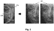
- a method according to the present invention is a method for optimal division of the digital image, meaning that the contours of the obtained plurality of partial images run across the digital image, while methods known in the prior art provide cutting lines along the contours of the digital image.
- the digital image comprises height information for each pixel and the algorithm for determining optimal division of the digital image into a plurality of parts is based on height information of the plurality of pixels.
- the digital image may comprise further information for each pixel, for example (but not limited to) gloss information and transparency information, and the algorithm for determining optimal division of the digital image into a plurality of parts is based on said further information, in particular on gloss and/or transparency information.
- the image processing step c) further comprises adding an excess of pixels to the plurality of partial images, such that the plurality of partial images exceed the defined plurality of accompanying contours, wherein cutting step f is performed after printing step c to remove a part of the substrate containing the excess of pixels from the partial image printed in step c.
- cutting step f is performed after printing step c to remove a part of the substrate containing the excess of pixels from the partial image printed in step c.
- the cutting is performed at an angle of between 0.2° and 3°, preferably between 0.5° and 2°, relative to the normal vector of the printed surface, such that after cutting and assembling, the panels touch one another at the top edge side, i.e. the edges of the adjacent printed partial images touch one another. Substrate visibility in the final (assembled) print product is hence further reduced.
- the cutting step f is performed prior to the printing step c.
- the method according to the present embodiment may be preferred in case the cutting step is detrimental for the printed material or in case the printed structure is too fragile for the cutting process.
- the algorithm for determining optimal division of the digital image into a plurality of parts provides a cutting trajectory through areas of the digital image with high surface roughness (of the final printed product).
- surfaces having a surface roughness Ra of below 0.2 ⁇ m may have a glossy appearance.
- High surface roughness in the context of the present invention may therefore be construed as a surface having a Ra of above 0.2 ⁇ m, in particular Ra >> 0.2 ⁇ m. It is an advantage of the present embodiment, that glossy areas (i.e. smooth areas having a low surface roughness.) in the image are avoided in the cutting step, such that the transition between two adjacent panels is less visible.
- the algorithm for determining optimal division of the digital image into a plurality of parts provides a cutting trajectory through areas of the digital image with dark colors.
- the dark colored areas show less pronounced transitions between the partial images.
- other factors such as the used cutting technique, substrate material and printing material may be of influence in determining the preferred color range for cutting.
- the algorithm for determining optimal division of the digital image into a plurality of parts comprises a step of avoiding the cutting trajectory to go through critical 3D shapes (such as overhanging parts or particularly known fragile (micro) structures).
- the algorithm for determining optimal division of the digital image into a plurality of parts comprises a step of smoothening the obtained trajectory in order to avoid sharp direction transitions in the trajectory.
- the algorithm for determining optimal division of the digital image into a plurality of parts comprises a step of taking into account requirements and/or restrictions of the used cutting technology. For example selection of criteria based on cutting technology induced artifacts or capabilities of the cutting technology, e.g. critical curvature of the cutting trajectory above which the risk of damage significantly increases.
- the substrate is not particularly limited to any kind.
- the substrate is selected from the group consisting of vinyl, paper, PVC, PET, dibond, textile, foam, cardboard, wood, ceramics and metals.
- the algorithm for determining optimal division of the digital image into a plurality of parts provides contours of the plurality of partial images, wherein the contours of the plurality of partial images are determined with a constraint that the obtained plurality of panels can be assembled to form a mechanically stable printed product.
- a preferential form of the cutting trajectory may be introduced, e.g. a puzzle like structure.
- a 3D-image is adapted at the location of the determined cutting trajectory to reduce the visibility of the transversal area after cutting.
- the printed layers building the height of the image at the location of the cutting trajectory can be printed in the same color, in particular the same color as the top layer of the digital image at that location.
- the present invention relates to a printed object, obtained with a method according to the present invention.
- the printed object is fine art reproduction.
- the printed object comprises a plurality of parts that are assembled after production of the plurality of parts to form the printed object.
- the present invention relates to a printer comprising a controller configured for performing a method according to the present invention.
- the controller comprises an algorithm for determining optimal division of the digital image into a plurality of parts based on the color information of the plurality of pixels of the digital image.
- the controller comprises an algorithm for determining optimal division of the digital image into a plurality of parts based on the height information of the plurality of pixels of the digital image.
- the digital image may comprise further information for each pixel, for example (but not limited to) gloss information and transparency information
- the controller comprises an algorithm for determining optimal division of the digital image into a plurality of parts based on said further information, in particular on gloss and/or transparency information.
- the controller comprises an algorithm for determining optimal division of the digital image into a plurality of parts based on critical feature information of the digital image.
- the controller comprises a user interface for entering input data based on which the algorithm generates a trajectory for optimal division of the digital image.
- the input data comprise at least one selected from the group consisting of: requirements and/or restrictions of the cutting technology; substrate type; ink type; maximum size of division parts of the product; number of division parts of the product; and user defined critical features in the digital image.
- the presented invention relates to a method that aims at producing a cutting trajectory design that preserves critical features (optionally user defined) of printed matter, in particular relief printed matter.
- the cutting trajectory is formed by a set of points characterized by their coordinates in the digital (relief) image.
- the cutting trajectory is then submitted to a cutting machine (e.g. CNC-cutter-milling machine; laser-beam cutter; water-beam cutter, etc) to produce a plurality of substrates (e.g. panels, tiles) comprising a corresponding plurality of parts of the digital (relief) image.
- the plurality of parts of the digital image can be printed prior or after cutting the substrate into the plurality of substrates.
- the plurality of substrates can be packaged, shipped and reassembled to form the complete (relief) printed product, e.g. a fine art reproduction.
- the cutting trajectory used in a method according to the present invention is generated based on specific features such as (but not limited to) color, height, gloss and translucency of a digital image to be printed and in accordance with a method (from now on termed "cutting trajectory generation") described below.
- Trajectory generation starts with defining a cutting trajectory search area within the digital image to be printed. This area defines a region where the image or the (printed) substrate can be divided into two parts, based on the size of the print and the maximum size of the printing area and/or the available maximum substrate size.
- the cutting trajectory is enclosed by the search area and crosses this search area (e.g. having a rectangular shape) in a first direction, for example a vertical direction (e.g. from the top to the bottom of the search area).
- the same procedure can be performed in a second direction substantially perpendicular to the first direction (e.g. from left to right), to produce tiles that can be easily handled.
- the cutting trajectory generation of the present example comprises three main steps, which will be further described in the sections below (numbering of the steps corresponds to the numbering in Fig. 1 :
- other input elements may be (but not limited to) cutter capabilities, substrate and marking material characteristics (not shown).
- Step 1 Setting the critical feature criterion
- the cutting trajectory generation starts with specifying a criterion which describes the areas of the digital image or the printed substrate that the cutting trajectory path should preferably not cross: the critical feature criterion.
- the critical feature criterion is based on knowledge of the risk of damaging the printed matter during cutting and prevents that the cutting trajectory runs through areas of the digital image or the printed substrate with a high risk of being damaged during cutting. This criterion may be dependent on image information, but also on the used cutting technique and/or used print substrates and/or used print materials.
- the criterion may be (partially) user defined, and may be (partially) automatically determined or a combination of both.
- the digital image may comprise color and/or height (relief) and/or gloss and/or translucency information. Based on the print input, the user may specify critical features that must be preserved and hence preferably avoided by the cutting process. For example:
- the critical features criterion may be represented as a grey level image (critical features map), wherein the grey level indicates the importance of regions in the digital image containing critical features and the differences in grey levels in the critical features map indicates the relative importance critical features in the digital image. For example, regions containing highly critical features are considered to be highly important regions to avoid in the cutting process and such regions are indicated with high grey value (black). The other way around is also a possibility. This is a matter of convention.
- the critical features criterion may be determined by using the following features of the digital image:
- the cutting trajectory generation may comprise detection (automatic or manually) of isolated features having a critical shape, for example:
- a map indicating the location of isolated features having a critical shape, 1d in Fig.1 may be manually or semi-automatically determined.
- the global criterion may be expressed as a linear combination of multiple image criteria, taking into account the relative importance of a single image criterion by weight factors as expressed in equation 1.
- the global criterion shown in Fig. 1 is composed by adding the height map, the color map, the gloss map and the isolated features with critical shape map with all weight factors being 0.25.
- the grey-level of the dots in the global criterion map 1e indicates the importance of avoidance of a certain area in the cutting process.
- Step 2 Cutting trajectory initialization
- the user manually draws a cutting trajectory by approximately indicating one or more regions where the cutting trajectory should be located.
- high precision (which would be time consuming and prone to errors) is not required because in a next step of the cutting trajectory generation, refinement of the initially indicated cutting trajectory will be performed.
- an algorithm such as a minimum cost path search algorithm like the Dijkstra method may be used to determine an initial cutting trajectory.
- a minimum cost path search algorithm like the Dijkstra method
- a global criterion 1e based on a critical feature preservation map allowed to automatically select an initial cutting trajectory 2a that preserves the region with high lightness, high elevation, and high gloss and containing isolated features with critical shape. Criteria such as edges related to strong elevation differences (height map gradients) and other criteria disclosed above (but not limited to those), may also be used in defining a global criterion.
- the initial cutting trajectory 2a may show abrupt and/or sharp direction changes, oscillations and may be too close from edges of critical features. That is the reason why, a refinement stage is proposed as Step 3.
- Step 3 Cutting trajectory refinement:
- the refinement step consists in producing a cutting trajectory, C that crosses the search area under the following two constraints:
- Cutting trajectory refinement may be inspired by methods and/or algorithms known in the prior art, for example the so called active contour method (also called snake method or algorithm, see 4 in Fig. 1 ). This class of algorithms is used for detecting the boundaries of shapes in an image.
- the partial differential equation can be minimized using approaches known from prior art.
- the coordinates of the starting point and end point of the cutting trajectory are the boundary conditions for solving the partial differential equation.
- Minimizing E ensures that the cutting trajectory C satisfies the two previously mentioned constraints, i.e. it is smooth and it crosses the search area at points where the critical features criterion is used as a guide towards the desired solution.
- the minimization of E crit may involve the generation of a force field (based on a criterion map, e.g. the global criterion map, see 4 in Fig. 1 ) that will guide the cutting trajectory to areas where the criterion is low, i.e. where cutting is least critical.
- a criterion map e.g. the global criterion map, see 4 in Fig. 1
- a repulsive force field that is derived from the critical feature criterion (e.g. global criterion) may be computed.
- the force field may be designed to provide the desired properties to the final curve. For example, the user may want the curve to be as far as possible from the critical features. So a repulsive force vector flow centered on each feature can be built.
- the force field will guide the cutting trajectory through the search region where the force field is neutral, e.g. force is zero or force cancellation (force vectors of adjacent pixels at least partially cancel one another).
- the evolution of the cutting trajectory will be implemented by a snake algorithm parameterized by the, so determined, repulsive force field.
- Repulsive force fields regarding critical features can be determined based on several criteria and also based on a combination of criteria. For example:
- This method is particularly suitable for cutting trajectory generation in cases wherein (but not limited to):
Landscapes
- Engineering & Computer Science (AREA)
- General Engineering & Computer Science (AREA)
- Physics & Mathematics (AREA)
- General Physics & Mathematics (AREA)
- Theoretical Computer Science (AREA)
- Multimedia (AREA)
- Signal Processing (AREA)
- Image Processing (AREA)
- Ink Jet (AREA)
Applications Claiming Priority (1)
| Application Number | Priority Date | Filing Date | Title |
|---|---|---|---|
| EP16159546 | 2016-03-10 |
Publications (1)
| Publication Number | Publication Date |
|---|---|
| EP3216616A1 true EP3216616A1 (fr) | 2017-09-13 |
Family
ID=55696889
Family Applications (1)
| Application Number | Title | Priority Date | Filing Date |
|---|---|---|---|
| EP17159486.4A Withdrawn EP3216616A1 (fr) | 2016-03-10 | 2017-03-07 | Procédé d'impression |
Country Status (2)
| Country | Link |
|---|---|
| US (1) | US20170262742A1 (fr) |
| EP (1) | EP3216616A1 (fr) |
Cited By (1)
| Publication number | Priority date | Publication date | Assignee | Title |
|---|---|---|---|---|
| WO2019076436A1 (fr) * | 2017-10-16 | 2019-04-25 | Hp Indigo B.V. | Appareil de traitement d'images |
Families Citing this family (1)
| Publication number | Priority date | Publication date | Assignee | Title |
|---|---|---|---|---|
| US10997784B2 (en) | 2018-12-18 | 2021-05-04 | Microsoft Technology Licensing, Llc | Generating space models from map files |
Citations (4)
| Publication number | Priority date | Publication date | Assignee | Title |
|---|---|---|---|---|
| US4631596A (en) | 1984-02-24 | 1986-12-23 | Canon Kabushiki Kaisha | Image communications apparatus for long-size copy image |
| EP0971532A2 (fr) * | 1998-07-10 | 2000-01-12 | Canon Kabushiki Kaisha | Procédé et appareil de commande d'impression |
| US20030044200A1 (en) * | 2001-08-28 | 2003-03-06 | Xerox Corporation | Method and arrangement for providing alignment indicia in a printed image |
| EP1650954A1 (fr) | 2004-10-21 | 2006-04-26 | Noritsu Koki Co., Ltd. | Appareil de traitement d'image |
-
2017
- 2017-03-03 US US15/449,698 patent/US20170262742A1/en not_active Abandoned
- 2017-03-07 EP EP17159486.4A patent/EP3216616A1/fr not_active Withdrawn
Patent Citations (4)
| Publication number | Priority date | Publication date | Assignee | Title |
|---|---|---|---|---|
| US4631596A (en) | 1984-02-24 | 1986-12-23 | Canon Kabushiki Kaisha | Image communications apparatus for long-size copy image |
| EP0971532A2 (fr) * | 1998-07-10 | 2000-01-12 | Canon Kabushiki Kaisha | Procédé et appareil de commande d'impression |
| US20030044200A1 (en) * | 2001-08-28 | 2003-03-06 | Xerox Corporation | Method and arrangement for providing alignment indicia in a printed image |
| EP1650954A1 (fr) | 2004-10-21 | 2006-04-26 | Noritsu Koki Co., Ltd. | Appareil de traitement d'image |
Cited By (2)
| Publication number | Priority date | Publication date | Assignee | Title |
|---|---|---|---|---|
| WO2019076436A1 (fr) * | 2017-10-16 | 2019-04-25 | Hp Indigo B.V. | Appareil de traitement d'images |
| US11232335B2 (en) | 2017-10-16 | 2022-01-25 | Hp Indigo B.V. | Printing sub-images to create complete image |
Also Published As
| Publication number | Publication date |
|---|---|
| US20170262742A1 (en) | 2017-09-14 |
Similar Documents
| Publication | Publication Date | Title |
|---|---|---|
| US20180143617A1 (en) | Method for printing colored object of 3d printer | |
| US9552634B2 (en) | Methods and systems for automated selection of regions of an image for secondary finishing and generation of mask image of same | |
| RU2709860C1 (ru) | Классификаторы плотности на основе областей плоскости | |
| US20180307208A1 (en) | Method of inwardly decreasing coloring contour of color 3d object | |
| US20160210088A1 (en) | Nesting method and apparatus | |
| EP3439280A1 (fr) | Procédé et système de mise en forme d'objet | |
| US8923616B2 (en) | Image-content dependent print cutting system | |
| Karow | Font technology | |
| US20120223996A1 (en) | Print data compensation for variations in paper position within a printing system | |
| US20070146737A1 (en) | Print data generating apparatus a print data generating method | |
| US9272528B2 (en) | Image processing device and method expanding aquired image data into printing data corresponding to a multi-layer image with color values less than or equal to a maximum ink amount | |
| US20170262742A1 (en) | Method of printing | |
| WO2000051827A1 (fr) | Procede de fabrication de cartes a couches generees par ordinateur et cartes a couches obtenues selon ce procede | |
| JP4886539B2 (ja) | 画像処理方法 | |
| CN113619121A (zh) | 三维物体打印方法、数据处理装置、计算机设备 | |
| US20220180791A1 (en) | Display medium, processing device, and processing program | |
| EP2277713B1 (fr) | Objet imprimé, appareil de formation d'objet imprimé et procédé de formation d'objet imprimé | |
| CN106256545A (zh) | 图像处理装置以及图像处理方法 | |
| EP3346690B1 (fr) | Procédé de découpage et d'impression d'objet 3d multicolore | |
| US20190064773A1 (en) | Method for indenting coloring areas of colored 3d object | |
| JP4225337B2 (ja) | 画像処理装置及び画像処理方法 | |
| JP5738613B2 (ja) | インクジェットプリンタおよび画像形成方法 | |
| JP2016210082A (ja) | プリンタ | |
| US10471730B2 (en) | Method of relief printing and a relief printer | |
| US11094231B2 (en) | Metal poster with relief printed frame |
Legal Events
| Date | Code | Title | Description |
|---|---|---|---|
| PUAI | Public reference made under article 153(3) epc to a published international application that has entered the european phase |
Free format text: ORIGINAL CODE: 0009012 |
|
| STAA | Information on the status of an ep patent application or granted ep patent |
Free format text: STATUS: THE APPLICATION HAS BEEN PUBLISHED |
|
| AK | Designated contracting states |
Kind code of ref document: A1 Designated state(s): AL AT BE BG CH CY CZ DE DK EE ES FI FR GB GR HR HU IE IS IT LI LT LU LV MC MK MT NL NO PL PT RO RS SE SI SK SM TR |
|
| AX | Request for extension of the european patent |
Extension state: BA ME |
|
| STAA | Information on the status of an ep patent application or granted ep patent |
Free format text: STATUS: REQUEST FOR EXAMINATION WAS MADE |
|
| 17P | Request for examination filed |
Effective date: 20180313 |
|
| RBV | Designated contracting states (corrected) |
Designated state(s): AL AT BE BG CH CY CZ DE DK EE ES FI FR GB GR HR HU IE IS IT LI LT LU LV MC MK MT NL NO PL PT RO RS SE SI SK SM TR |
|
| STAA | Information on the status of an ep patent application or granted ep patent |
Free format text: STATUS: THE APPLICATION IS DEEMED TO BE WITHDRAWN |
|
| 18D | Application deemed to be withdrawn |
Effective date: 20191001 |