EP3216751A1 - Dispositif de soutirage, fût et procédé de soutirage - Google Patents
Dispositif de soutirage, fût et procédé de soutirage Download PDFInfo
- Publication number
- EP3216751A1 EP3216751A1 EP17000398.2A EP17000398A EP3216751A1 EP 3216751 A1 EP3216751 A1 EP 3216751A1 EP 17000398 A EP17000398 A EP 17000398A EP 3216751 A1 EP3216751 A1 EP 3216751A1
- Authority
- EP
- European Patent Office
- Prior art keywords
- beverage
- gas
- expansion device
- attachment
- channel
- Prior art date
- Legal status (The legal status is an assumption and is not a legal conclusion. Google has not performed a legal analysis and makes no representation as to the accuracy of the status listed.)
- Granted
Links
Images


Classifications
-
- B—PERFORMING OPERATIONS; TRANSPORTING
- B67—OPENING, CLOSING OR CLEANING BOTTLES, JARS OR SIMILAR CONTAINERS; LIQUID HANDLING
- B67D—DISPENSING, DELIVERING OR TRANSFERRING LIQUIDS, NOT OTHERWISE PROVIDED FOR
- B67D1/00—Apparatus or devices for dispensing beverages on draught
- B67D1/02—Beer engines or like manually-operable pumping apparatus
-
- B—PERFORMING OPERATIONS; TRANSPORTING
- B67—OPENING, CLOSING OR CLEANING BOTTLES, JARS OR SIMILAR CONTAINERS; LIQUID HANDLING
- B67D—DISPENSING, DELIVERING OR TRANSFERRING LIQUIDS, NOT OTHERWISE PROVIDED FOR
- B67D1/00—Apparatus or devices for dispensing beverages on draught
- B67D1/0003—Apparatus or devices for dispensing beverages on draught the beverage being a single liquid
- B67D1/0004—Apparatus or devices for dispensing beverages on draught the beverage being a single liquid the beverage being stored in a container, e.g. bottle, cartridge, bag-in-box, bowl
-
- B—PERFORMING OPERATIONS; TRANSPORTING
- B67—OPENING, CLOSING OR CLEANING BOTTLES, JARS OR SIMILAR CONTAINERS; LIQUID HANDLING
- B67D—DISPENSING, DELIVERING OR TRANSFERRING LIQUIDS, NOT OTHERWISE PROVIDED FOR
- B67D1/00—Apparatus or devices for dispensing beverages on draught
- B67D1/04—Apparatus utilising compressed air or other gas acting directly or indirectly on beverages in storage containers
- B67D1/0412—Apparatus utilising compressed air or other gas acting directly or indirectly on beverages in storage containers the whole dispensing unit being fixed to the container
-
- B—PERFORMING OPERATIONS; TRANSPORTING
- B67—OPENING, CLOSING OR CLEANING BOTTLES, JARS OR SIMILAR CONTAINERS; LIQUID HANDLING
- B67D—DISPENSING, DELIVERING OR TRANSFERRING LIQUIDS, NOT OTHERWISE PROVIDED FOR
- B67D1/00—Apparatus or devices for dispensing beverages on draught
- B67D1/04—Apparatus utilising compressed air or other gas acting directly or indirectly on beverages in storage containers
- B67D1/045—Apparatus utilising compressed air or other gas acting directly or indirectly on beverages in storage containers using elastic bags and pistons actuated by air or other gas
-
- B—PERFORMING OPERATIONS; TRANSPORTING
- B67—OPENING, CLOSING OR CLEANING BOTTLES, JARS OR SIMILAR CONTAINERS; LIQUID HANDLING
- B67D—DISPENSING, DELIVERING OR TRANSFERRING LIQUIDS, NOT OTHERWISE PROVIDED FOR
- B67D1/00—Apparatus or devices for dispensing beverages on draught
- B67D1/08—Details
- B67D1/0801—Details of beverage containers, e.g. casks, kegs
- B67D1/0802—Dip tubes
-
- B—PERFORMING OPERATIONS; TRANSPORTING
- B67—OPENING, CLOSING OR CLEANING BOTTLES, JARS OR SIMILAR CONTAINERS; LIQUID HANDLING
- B67D—DISPENSING, DELIVERING OR TRANSFERRING LIQUIDS, NOT OTHERWISE PROVIDED FOR
- B67D1/00—Apparatus or devices for dispensing beverages on draught
- B67D1/08—Details
- B67D1/12—Flow or pressure control devices or systems, e.g. valves, gas pressure control, level control in storage containers
- B67D1/1252—Gas pressure control means, e.g. for maintaining proper carbonation
-
- B—PERFORMING OPERATIONS; TRANSPORTING
- B67—OPENING, CLOSING OR CLEANING BOTTLES, JARS OR SIMILAR CONTAINERS; LIQUID HANDLING
- B67D—DISPENSING, DELIVERING OR TRANSFERRING LIQUIDS, NOT OTHERWISE PROVIDED FOR
- B67D1/00—Apparatus or devices for dispensing beverages on draught
- B67D1/08—Details
- B67D1/0801—Details of beverage containers, e.g. casks, kegs
- B67D2001/0822—Pressurised rigid containers, e.g. kegs, figals
- B67D2001/0825—Pressurised rigid containers, e.g. kegs, figals details of dip tube
Definitions
- the following invention relates to a dispensing attachment for liquid containers such as beverage barrels, especially beer kegs, a beverage keg with the tap attachment and a corresponding tapping method.
- dispensers are known for placement on beer vessels, such as cans or barrels containing several liters of beer, which allow beer to be poured by exposing the contents to gas such as CO 2 and providing such carbonic acid pressure the beer from the container is promoted and it is attractively and tastefully filled with appropriate foam crown in glasses.
- gas such as CO 2
- the tapping of the beer then takes place via a tap, which is often arranged close to the ground on a vertical wall or on the pressure cap on the lid of the can or barrel.
- a printing attachment of this kind which can be placed on beverage cans to pressurize the beverage by means of a arranged in the pressure lid carbon dioxide cartridge with gas, is in the DE 10 2007 032 414 B4 described.
- a pressure attachment which in addition to the pressurization also allows an omission of the drink is in DE 10 2009 041 115 A1 disclosed.
- This hood-like pressure tap attachment that can be placed on beer containers, includes a Gaszu 1500rohr, there called sword, which extends from the pressure tap attachment in the beer container, and further a CO 2 cartridge, via a valve arrangement with the Gaszu 1500rohr in fluidic Connection stands.
- the CO 2 cartridge is arranged in the hood and displaceable by an actuating device against a mandrel, so that the mandrel penetrate a closure of the cartridge neck and can release a channel for the escape of the gas from the cartridge, extending to a gas inlet opening of the gas supply pipe extends.
- the pressure tap attachment has a telescopic outlet tube which, at its end pointing into the hood, opens into a valve which can be opened by a lever arrangement, which can be fluidically connected to a riser channel which extends into the gas feed tube.
- the amount of carbon dioxide in the beverage may adversely vary. So may be present at the beginning of the tapping process too high a content, so that the draft beer foams excessively, while with increasing emptying of the beverage keg, the content of carbon dioxide can decrease, so that the beer tapped then tastes stale.
- US 534 541 A discloses a tap with an elongated dispensing tube that projects into the interior of the barrel with one end portion.
- a longitudinally movable Gaszu melt is integrated in the dispensing tube.
- an expansion device is attached, which can be inflated via the gas supply pipe so as to provide a desired pressure for the pin in the beverage keg.
- the expansion device can be drawn into the extended dispensing tube through the movable gas supply tube.
- Another dispensing device which also avoids the contact of the beverage with a pressure medium is in US 1 977 862 A described.
- an expansion device integrated into the dispensing attachment is provided, which is transferred into a barrel bunghole after the attachment of the dispensing attachment.
- the beverage outlet tube is used as a guide or support device for the expansion device, which extends in the use arrangement of the dispensing attachment to just above the bottom of the barrel.
- lateral openings for receiving the drink from the barrel are provided at this bottom end of the beverage outlet pipe lateral openings for receiving the drink from the barrel are provided.
- the expansion device is sealingly attached, which can be inflated via a gas valve in the dispensing head, so as to pressurize the present in the barrel drink with pressure to tap.
- An inventive dispensing attachment is provided for placement on a beverage barrel dispensing attachment and beverage keg are so matched to each other in terms of their geometry that the dispensing nozzle can be placed on such, so predetermined, barrel when it is to be put into operation.
- the dispensing attachment has a base body having one or more fastener (s) with which it can be mounted on the beverage keg.
- the fastening elements can be designed for releasable or non-detachable fastening of the dispensing attachment.
- the nozzle attachment to a connection device for a gas source and a first valve assembly and a gas duct with an orifice, which, when the dispensing head sits on the beverage barrel, in the interior thereof.
- the gas channel can be opened and closed, so that gas when connected to a gas source, even if the dispensing unit is just arranged in operating arrangement on the beverage keg (ie Zapfhneschaft exists) can be supplied from the gas source with a specific, preset pressure.
- an actuating device is provided, with which the valve arrangement for opening the gas channel can be actuated.
- the connection device can be actuated to allow gas to flow, ie to release the fluidic connection to the gas source - this can be realized with a separate actuator or by coupling with the actuator of the valve assembly.
- the nozzle attachment to a second valve assembly and a riser channel with an orifice, which points in operation of the dispensing nozzle on the beverage barrel in the interior, and an outlet provided by a tap.
- the second valve arrangement which can be actuated with a further actuating device, opens and closes the connection between the riser channel and the outlet, so that upon actuation of this actuating device the beverage is tapped from the barrel can be.
- the dispensing attachment has a gas-tight expansion device, which surrounds the gas channel at its mouth, so that supplied gas does not reach the beverage present in the beverage barrel, but instead reaches the expansion device.
- the gas-tight expansion device can be converted from a non-expanded state to an expanded state.
- the expansion device is designed so that in the expanded state and consequently in the operating arrangement it has a volume which corresponds at least to an internal volume of the beverage keg to which the tap attachment can be placed. It is also conceivable that the expansion device in its fully expanded state may have a volume which is slightly smaller than the inner volume of the beverage keg, so that the expanded expansion device does not completely fill the inner volume of the keg.
- the expansion device should be designed so that they can have 100% of the inner volume of a predetermined beverage keg or even more in the expanded state - the latter, of course, can only fully unfold outside the barrel.
- the expansion device in the barrel, it will not be able to assume a larger volume than the internal volume of the keg.
- the over-dimensioning merely ensures that the expansion device can completely fill the inner volume of the drum.
- the tap attachment has a stabilizing device formed by a rod which, in FIG or on the expansion device and stabilizes it in the transition from the unexpanded state to the expanded state.
- the stabilizing device is formed by the rod with an internal channel, so that a gas supply pipe for supplying gas into the expansion device is provided.
- the gas supply pipe is attached so that the internal duct continues the gas duct.
- a gas outlet opening can be present anywhere along the rod or tube, both at the top, ie adjacent to the mouth of the gas channel, or at the distal end, so that the inner channel extends completely through the rod, or somewhere in between. It can also be provided more than one gas outlet opening.
- the rod extends so far away from the base body of the dispensing attachment that it protrudes in the interior of the beverage barrel when the dispensing attachment is arranged, preferably in or parallel to the longitudinal axis of the beverage barrel.
- the tubes that extend from the tap attachment into the beverage barrel all serve to drink, so that the beer to be tapped by the inside of the barrel, sometimes reaching to the keg beverage outlet pipe rises
- the drink through the Steigkanal with the mouth which is located near the tap attachment, pushed through the tap.
- the tube which extends through the container and is used to stabilize the expansion device, is provided for inflating the expansion device.
- the length of the rod is adapted to that of the expansion device, and at least corresponds to its length in its unexpanded state in order to stabilize the expansion of the expansion device can.
- the expansion device disposed at the mouth of the gas channel thus also surrounds the rod or the gas supply tube, through which the gas is supplied into the expansion device.
- the expansion device With the gas discharge opening provided by the gas supply pipe at the lower end of the expansion device with an expansion device having different areas in terms of their expansion capability, can be achieved, that the expansion device now initially expands close to the ground, so that the present in the barrel beverage is pushed from bottom to top in the direction of riser.
- a stabilizing device may consist of a plurality of rods which are hingedly connected to each other and optionally biased to form a scaffold, similar to an umbrella frame. Such a linkage may also be at least partially attached to the wall of the expansion device.
- the gas-tight expansion device may be formed by a balloon of an elastic material having a smaller surface area in the unexpanded state than in the expanded state.
- the gas-tight expansion device may be through a bag or bellows of an inelastic or at least less elastic material than the balloon, wherein such expansion device is present folded in the unexpanded state and thus has only a small volume.
- such an expansion device the surface of which does not differ substantially between the unexpanded and the expanded state, is deployed by the supplied gas to thereby occupy a correspondingly larger volume.
- the nozzle attachment may have a suitable adapter.
- Suitable adapters include, for example, flanges or fittings that are detachable - e.g. by screw - or insoluble, z.
- Example, by welding or soldering, can be attached to the mouth of the gas channel and have one or more contact portions for gas-tight attachment of the expansion device. This can be done detachably or permanently, for example by means of gluing, welding, clipping or clamping.
- the adapter may be configured to releasably secure the expansion device to the gas channel such that, as it were, either the adapter or the expansion device is releasably secured, so that, if reused, the expansion device may be easily detached for cleaning or replacement can.
- the adapter can be used to attach the stabilizer.
- the adapter can be used to produce the glass flow, ie the fluid Connection between the gas channel and the inner channel of the Gaszu Publishedrohres be used.
- a device for keeping the riser channel is arranged at the mouth of the riser channel.
- This can be formed by a curved sieve or a remote basket device with side openings.
- the curvature or the paragraph extends away from the riser channel, ie in the direction of the barrel interior, when the dispensing attachment is arranged on a beverage barrel. This prevents that the mouth of the riser channel can be blocked by the expansion device in a partially expanded state before reaching full expansion. Even if the expansion device abuts against the inside of the drum facing side of the screen or basket device, the lateral openings remain free.
- An alternative device for keeping the riser channel free can be a crown device arranged around its mouth, which is formed by a plurality of wedge-like boundary walls, which tap radially toward the mouth and whose height increases towards the mouth.
- a device for keeping the riser channel free can be part of the expansion device.
- This may have on its outer wall at least one bead-like depression which extends to the mouth of the riser channel, approximately in a spiral shape. It can also be two or more parallel to the mouth of the riser channel extending webs, each of which a pair in the expanded state of the expansion device forms a fluid channel on the inner wall of the beverage keg, when the expansion device, respectively.
- the dispensing attachment is arranged in operating order on the beverage barrel.
- the dispensing attachment can have a connection device which can be connected to an external gas source via a connecting line.
- an internal gas source preferably a gas cartridge
- a holder is provided in the main body of the dispensing attachment. The dispenser then has a connection device which is connected via a connecting line to the internal gas source. The holder can be designed so that the gas cartridge can be replaced if a multiple use of the tap attachment is provided.
- actuating device for actuating the first valve arrangement and the second actuating device for actuating the second valve arrangement of the dispensing unit are combined in a common device in which both functionalities are coupled.
- the main body of the dispensing unit may be constructed in the manner of a bracket or framework, it is preferred for the base unit to be hood-shaped as a pressure hood, wherein the fastening element can be provided by a peripheral hood rim which is offset from the hood side wall.
- the hood edge, the z. B. can be equipped with a circumferential Umgriffelement or distributed Umgriffierin, comes with the arrangement of the tap attachment on the drinks barrel with an upper edge of the beverage barrel engaged.
- An inventive arrangement of beverage keg and dispensing attachment is characterized in that the dispensing attachment is an inventive dispensing attachment, wherein the expansion device extends into the barrel interior.
- the beverage keg or the tap attachment (or both) at least one spacer element, which at least one inner wall of the beverage keg, z. B. the inner shell surface extends. It can also be provided several such spacers.
- a spacer element provides a fluid channel on the wall of the barrel, so that even with very widely expanded expansion device still liquid can get up from the bottom of the drum in the direction of the riser mouth.
- spacer elements which may be, for example, rod-shaped, tubular or channel-shaped, can also provide drum base and drum cover for fluid channels so that fluid communication between the drum base, inner shell surface of the beverage keg and the drum cover can take place as far as the mouth of the riser channel.
- the spacer elements may be attached to the drum wall or be inserted like a cage, the inner walls of the barrel can also be made already profiled; but it can also be loose spacer elements in the barrel, which lie with the expanding expansion device to the wall.
- a preferred spacer element may be a gutter device with a cross-sectional profile, which may be open u-, v-, c- or w-shaped or a closed hollow profile.
- the cross-sectional profile tapers from a lower opening in relation to the arrangement in the beverage barrel to an upper opening, wherein the wall thickness or the wall stability of the gutter device increases from the lower opening to the upper opening.
- This gutter device is disposed on the shell inner surface of the beverage keg and extends from the bottom to the top, so that the bottom opening at the bottom and the top opening abuts the ceiling, wherein the gutter device at both ends recesses or passage openings which a fluid channel from the bottom of the beverage keg through the gutter device to the ceiling of the beverage keg provides, even if the expansion device is already far expanded.
- the gutter device may be made of an elastically or plastically deformable material and thus be pressed during expansion in contact with the expansion device first down in the area with thinner wall thickness / stability and then upwardly extending to the shell inner surface. This change in shape takes place only when the expansion device fills the entire interior of the beverage keg. This ensures that the fluid from the gutter device is finally pushed out into the riser channel.
- a spacer such as the bead-like depression or the adjacent webs provide in the expanded state of the expansion device for a fluid channel, which extends along the inner walls of the beverage keg, floor, inner surface and / or ceiling.
- a further process step may provide for the stabilization of the expansion device in the beverage-filled beverage keg upon the transition from the unexpanded state to the expanded state by a stabilizer, the gas for transferring the expander from the unexpanded state to the expanded state by the stabilizer he follows.
- This is designed as a gas supply pipe, which is surrounded by the expansion device and continues the gas passage.
- the beverage present in the beverage barrel has an unchanged carbon dioxide content until completely emptied, which is optimally adjusted when the beverage is bottled in the beverage barrel.
- the device according to the invention relates to a dispensing attachment both alone and in the arrangement on a beverage keg.
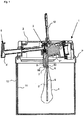
- an inventive dispensing attachment 1 in the arrangement according to the invention is also shown on a beverage barrel 10, wherein the representations differ only with respect to the expansion device 4.
- Fig. 1 shows the expansion device 4 in a non-expanded state, Fig. 2 in a partially expanded state and Fig. 3 in a nearly fully expanded state.
- the arranged on the beverage barrel 10 dispensing unit 1 has in the example shown a hood-like body 2, in which the hood edge 2 'represents or comprises a fastener with which the dispensing unit 1 is mounted on the beverage barrel 10.
- a gas channel 5 "runs here in several sections through the main body 2 and projects with a vertical, delimited by the mouth 50 section into the barrel 10.
- the gas supply pipe 5 is surrounded by a balloon 4, which represents the expansion device which is attached with an adapter 6 around the mouth end 50 of the gas channel 5' and this connects gas-tight with the gas supply pipe 5, which contributes to the stabilization of the balloon 4 in the beverage-filled barrel 10.
- the balloon 4 is made of an elastic, gas-tight material.
- the tap is a telescoping device shown in its telescoped arrangement.
- the tap 9 can be pushed back for storage and transport of the tap attachment 1 or in combination with the barrel 10 in a non-telescoped position, so that it does not protrude beyond the hood main body 2.
- Such a telescopic tap is in the DE 10 2009 041 115 A1 to which reference is thus made in its entirety.
- a spacer 11 In order to ensure the flow of beverage from the barrel 10 into the tap attachment 1 even with increasing expansion of the expansion device 4 to the fully expanded state in which the expansion device 4 fills the entire internal volume of the barrel 10, is a spacer 11 and an outwardly curved screening device 7 is provided at the mouth 80 of the riser 8.
- a gutter device 11 is shown as a spacer element, and in Fig. 5 the arrangement of two such gutter devices 11 in a beverage barrel 10 can be seen. Unlike shown, it is also possible that only such a gutter device 11 or even three or more are arranged in a barrel 10.
- the gutter device 11 has an open cross-sectional profile which tapers from the lower opening 111 to the upper opening 110, while the wall thickness inversely increases from the lower area 113 'to the upper 113, so that overall the wall stability increases from bottom to top ,
- the gutter device 11 in the arrangement in the barrel 10, in which they open with the side of the inner surface of the beverage keg 10 abuts and extends from the floor to the ceiling can provide a fluid communication between the floor and ceiling of the barrel 10, the gutter device 11 at both ends recesses as passage openings 112.
- the channel device 11 shown has a C-shaped cross-sectional profile, but it is also deviating profile shapes and closed profiles conceivable.
- the gutter device 11 can be made of an elastically or plastically deformable material, so that the gutter wall during expansion in contact with the expansion device 4, first down in the area 113 ', which has the lower stability by the larger cross section and the smaller wall thickness, and then after running upward to the upper area 113 is pressed against the barrel wall. This change in shape takes place only when the expansion device fills the entire interior of the beverage keg, so that the fluid in the gutter device 11 is finally pushed out.
- the expansion device 4 may be formed with a bead-like groove 4 ', as in Fig. 6 is shown by way of example.
- a bead-like groove two parallel webs are also conceivable, which likewise limit a fluid channel on the outer wall of the expansion device 4.
- the bead-like groove 4 ' runs like a thread or helically around the outer wall of the expansion device 4.
- the expansion of the expansion device 4 is effected by gas supply through the gas channel 5 " Fig. 7 is sketched from a gas cartridge 16, which is received in a holder provided for this purpose 18 in the base body 2 of the dispensing attachment.
- a connecting line 17, which in Fig. 4 is shown in dashed lines gas supplied from an external gas source.
- the connecting device 15 is designed according to the corresponding.
- a mechanism may be provided which pushes the gas cartridge against a mandrel of the connection device. This is also detailed in the DE 10 2009 041 115 A1 described.
- Fig. 7 the valve assembly 13 for opening the gas channel 5 "by means of the actuator 14, so that gas from the cartridge 16 (or via the connection line 17 from the external gas source) in the gas supply tube lying in the channel 5 'and from there into the expansion device (not in Fig. 7 can be shown).
- the actuating device 14 may, unlike the tap lever 12, for example, be designed as a rotating mechanism, as shown in the sketched Fig. 7 is indicated.
- Fig. 8 shows various devices for keeping the mouth 80 of the riser channel 8.
- a screening device 7 is shown, which is arched away from the mouth 80 in the direction of the barrel interior.
- the meshes of the sieve device 7 provide the lateral openings 7 'which, even with an expanded expansion device, keep a fluid connection between the inside of the trough and the riser channel 8 clear, as well as in FIG Fig. 3 you can see.
- Fig. 8b is shown as an alternative to a remote basket device 7 with openings 7 'in its cylindrical (or prismatic) side wall.
- Fig. 8c ) and d) show a designated as a crown device 70 device for keeping the riser 8.
- the boundary walls 71 define radial grooves 7 'which form the lateral openings.
- the gas used may, but need not be, CO 2 , which in the case of potential leaks of the expansion device, has no detrimental effect on the beverage.
Landscapes
- Devices For Dispensing Beverages (AREA)
Applications Claiming Priority (1)
| Application Number | Priority Date | Filing Date | Title |
|---|---|---|---|
| DE102016002938.2A DE102016002938A1 (de) | 2016-03-11 | 2016-03-11 | Zapfaufsatz, Getränkefass und Zapfverfahren |
Publications (3)
| Publication Number | Publication Date |
|---|---|
| EP3216751A1 true EP3216751A1 (fr) | 2017-09-13 |
| EP3216751A8 EP3216751A8 (fr) | 2018-05-16 |
| EP3216751B1 EP3216751B1 (fr) | 2020-05-13 |
Family
ID=59700286
Family Applications (1)
| Application Number | Title | Priority Date | Filing Date |
|---|---|---|---|
| EP17000398.2A Active EP3216751B1 (fr) | 2016-03-11 | 2017-03-13 | Dispositif de soutirage, fût et procédé de soutirage |
Country Status (2)
| Country | Link |
|---|---|
| EP (1) | EP3216751B1 (fr) |
| DE (1) | DE102016002938A1 (fr) |
Cited By (2)
| Publication number | Priority date | Publication date | Assignee | Title |
|---|---|---|---|---|
| CN113497255A (zh) * | 2021-06-30 | 2021-10-12 | 上海杰宁新能源科技发展有限公司 | 一种应用于氢燃料电池的精密流道钛金属接头 |
| CN121404668A (zh) * | 2025-12-26 | 2026-01-27 | 保视丽(上海)新材料科技有限公司 | 一种气液汲取结构及含有该结构的hdpe超净桶 |
Citations (8)
| Publication number | Priority date | Publication date | Assignee | Title |
|---|---|---|---|---|
| US534541A (en) | 1895-02-19 | Faucet and attachments therefor | ||
| US1977862A (en) | 1933-06-20 | 1934-10-23 | Harry A Uhler | Extractor |
| AU6478780A (en) * | 1979-11-28 | 1981-06-04 | Ampac Pty. Ltd. | Dispensing device |
| EP0312342A2 (fr) * | 1987-10-13 | 1989-04-19 | Wells F. Stackhouse | Un dispositif pour contrôler la distribution d'un liquide |
| US20090095776A1 (en) * | 2007-10-15 | 2009-04-16 | Peter Turner | Wine preservation system and method |
| DE102007032414B4 (de) | 2007-07-12 | 2009-09-03 | Fass-Frisch Gmbh | Druckaufsatz für getränkehaltige Gefäße und Verfahren zum Betreiben desselben |
| DE102009041115A1 (de) | 2009-09-15 | 2011-03-31 | Fass-Frisch Gmbh | Druck-Zapfaufsatz für Biercontainer und Verfahren zum Betreiben desselben |
| WO2013074782A1 (fr) * | 2011-11-15 | 2013-05-23 | Jett Innovation, Llc | Appareil et procédé pour déplacer de l'air à partir de conteneurs à vin |
Family Cites Families (3)
| Publication number | Priority date | Publication date | Assignee | Title |
|---|---|---|---|---|
| US3300102A (en) * | 1965-03-12 | 1967-01-24 | Budzich Tadeusz | Inflatable bag fluid dispensing device |
| CN100545077C (zh) * | 2002-11-29 | 2009-09-30 | 英博有限公司 | 关于桶的提升管 |
| GB0324905D0 (en) * | 2003-10-24 | 2003-11-26 | Interbrew Sa | Alcohol beverage appliance with gas connection |
-
2016
- 2016-03-11 DE DE102016002938.2A patent/DE102016002938A1/de not_active Ceased
-
2017
- 2017-03-13 EP EP17000398.2A patent/EP3216751B1/fr active Active
Patent Citations (8)
| Publication number | Priority date | Publication date | Assignee | Title |
|---|---|---|---|---|
| US534541A (en) | 1895-02-19 | Faucet and attachments therefor | ||
| US1977862A (en) | 1933-06-20 | 1934-10-23 | Harry A Uhler | Extractor |
| AU6478780A (en) * | 1979-11-28 | 1981-06-04 | Ampac Pty. Ltd. | Dispensing device |
| EP0312342A2 (fr) * | 1987-10-13 | 1989-04-19 | Wells F. Stackhouse | Un dispositif pour contrôler la distribution d'un liquide |
| DE102007032414B4 (de) | 2007-07-12 | 2009-09-03 | Fass-Frisch Gmbh | Druckaufsatz für getränkehaltige Gefäße und Verfahren zum Betreiben desselben |
| US20090095776A1 (en) * | 2007-10-15 | 2009-04-16 | Peter Turner | Wine preservation system and method |
| DE102009041115A1 (de) | 2009-09-15 | 2011-03-31 | Fass-Frisch Gmbh | Druck-Zapfaufsatz für Biercontainer und Verfahren zum Betreiben desselben |
| WO2013074782A1 (fr) * | 2011-11-15 | 2013-05-23 | Jett Innovation, Llc | Appareil et procédé pour déplacer de l'air à partir de conteneurs à vin |
Cited By (3)
| Publication number | Priority date | Publication date | Assignee | Title |
|---|---|---|---|---|
| CN113497255A (zh) * | 2021-06-30 | 2021-10-12 | 上海杰宁新能源科技发展有限公司 | 一种应用于氢燃料电池的精密流道钛金属接头 |
| CN113497255B (zh) * | 2021-06-30 | 2023-06-09 | 上海杰宁新能源科技发展有限公司 | 一种应用于氢燃料电池的精密流道钛金属接头 |
| CN121404668A (zh) * | 2025-12-26 | 2026-01-27 | 保视丽(上海)新材料科技有限公司 | 一种气液汲取结构及含有该结构的hdpe超净桶 |
Also Published As
| Publication number | Publication date |
|---|---|
| DE102016002938A1 (de) | 2017-09-14 |
| EP3216751B1 (fr) | 2020-05-13 |
| EP3216751A8 (fr) | 2018-05-16 |
Similar Documents
| Publication | Publication Date | Title |
|---|---|---|
| DE69904235T2 (de) | Behälter zum aufbewahren und abgeben von getränke, insbesondere von bier | |
| DE69933793T2 (de) | Ventilarmatur für Getränkebehälter, Getränkebehälter und Verfahren zum Füllen und Entleeren eines Getränkebehälters | |
| DE69635283T2 (de) | Zusammenlegbarer Behälter | |
| EP2209735B1 (fr) | Dispositif pour soutirer des liquides d'un récipient | |
| DE2531697C2 (de) | Vorrichtung zum Öffnen eines mit Flüssigkeiten, insbesondere unter Druck stehenden Getränken, gefüllten Behälters und zum Ausschenken | |
| EP3216751B1 (fr) | Dispositif de soutirage, fût et procédé de soutirage | |
| EP1763486B1 (fr) | Robinet de prise a usage unique pour recipient de liquide sous pression | |
| DE60301499T2 (de) | Abgabevorrichtung von unter druck stehender flüssigkeit | |
| DE102012021775B4 (de) | Vorrichtung zum Befüllen oder zum Entleeren eines Behältnisses | |
| DE69103705T2 (de) | Verbesserung eines Zapfhahnes. | |
| DE4330005A1 (de) | Vorrichtung zur Aufnahme und Abgabe von Flüssigkeiten | |
| DE102014008234A1 (de) | Ventilaufsatz, eine Befüllvorrichtung, eine Befüllanordnung und ein Verfahren zum Befüllen und Entleeren von Behältnissen mit Flüssigkeit | |
| DE2639918C3 (de) | Anschlußanordnung für Getränkebehälter | |
| DE2304538A1 (de) | Zusammenfaltbarer innenbehaelter fuer druckbehaelter | |
| AT410658B (de) | Ausgiessvorrichtung für einen flüssigkeitsbehälter | |
| EP2303760B1 (fr) | Bec de soutirage pour un contenant | |
| WO2017129176A1 (fr) | Dispositif de fermeture de récipients | |
| DE8214181U1 (de) | Ziehharmonikafoermiger Weinbehaelter | |
| DE19649567A1 (de) | Flüssigkeitsbehälter | |
| DE102010048902A1 (de) | Zapfeinrichtung | |
| DE102016117829A1 (de) | Zapfsystem zum Zapfen von Flüssigkeiten | |
| CH686527A5 (de) | Vorrichtung zum Aufpumpen von Reifen. | |
| DE3303357A1 (de) | Verfahren zum entleeren von unter druck stehenden zapfleitungen | |
| DE19503234A1 (de) | Vorrichtung zur Bevorratung von Flüssigkeiten | |
| DE9300928U1 (de) | Flaschenzapfanlage |
Legal Events
| Date | Code | Title | Description |
|---|---|---|---|
| PUAI | Public reference made under article 153(3) epc to a published international application that has entered the european phase |
Free format text: ORIGINAL CODE: 0009012 |
|
| STAA | Information on the status of an ep patent application or granted ep patent |
Free format text: STATUS: THE APPLICATION HAS BEEN PUBLISHED |
|
| AK | Designated contracting states |
Kind code of ref document: A1 Designated state(s): AL AT BE BG CH CY CZ DE DK EE ES FI FR GB GR HR HU IE IS IT LI LT LU LV MC MK MT NL NO PL PT RO RS SE SI SK SM TR |
|
| AX | Request for extension of the european patent |
Extension state: BA ME |
|
| STAA | Information on the status of an ep patent application or granted ep patent |
Free format text: STATUS: REQUEST FOR EXAMINATION WAS MADE |
|
| 17P | Request for examination filed |
Effective date: 20180307 |
|
| RBV | Designated contracting states (corrected) |
Designated state(s): AL AT BE BG CH CY CZ DE DK EE ES FI FR GB GR HR HU IE IS IT LI LT LU LV MC MK MT NL NO PL PT RO RS SE SI SK SM TR |
|
| STAA | Information on the status of an ep patent application or granted ep patent |
Free format text: STATUS: EXAMINATION IS IN PROGRESS |
|
| 17Q | First examination report despatched |
Effective date: 20190724 |
|
| GRAP | Despatch of communication of intention to grant a patent |
Free format text: ORIGINAL CODE: EPIDOSNIGR1 |
|
| STAA | Information on the status of an ep patent application or granted ep patent |
Free format text: STATUS: GRANT OF PATENT IS INTENDED |
|
| INTG | Intention to grant announced |
Effective date: 20191203 |
|
| GRAS | Grant fee paid |
Free format text: ORIGINAL CODE: EPIDOSNIGR3 |
|
| GRAA | (expected) grant |
Free format text: ORIGINAL CODE: 0009210 |
|
| STAA | Information on the status of an ep patent application or granted ep patent |
Free format text: STATUS: THE PATENT HAS BEEN GRANTED |
|
| AK | Designated contracting states |
Kind code of ref document: B1 Designated state(s): AL AT BE BG CH CY CZ DE DK EE ES FI FR GB GR HR HU IE IS IT LI LT LU LV MC MK MT NL NO PL PT RO RS SE SI SK SM TR |
|
| REG | Reference to a national code |
Ref country code: GB Ref legal event code: FG4D Free format text: NOT ENGLISH |
|
| REG | Reference to a national code |
Ref country code: CH Ref legal event code: EP |
|
| REG | Reference to a national code |
Ref country code: DE Ref legal event code: R096 Ref document number: 502017005196 Country of ref document: DE |
|
| REG | Reference to a national code |
Ref country code: AT Ref legal event code: REF Ref document number: 1270025 Country of ref document: AT Kind code of ref document: T Effective date: 20200615 |
|
| REG | Reference to a national code |
Ref country code: LT Ref legal event code: MG4D |
|
| REG | Reference to a national code |
Ref country code: NL Ref legal event code: MP Effective date: 20200513 |
|
| PG25 | Lapsed in a contracting state [announced via postgrant information from national office to epo] |
Ref country code: SE Free format text: LAPSE BECAUSE OF FAILURE TO SUBMIT A TRANSLATION OF THE DESCRIPTION OR TO PAY THE FEE WITHIN THE PRESCRIBED TIME-LIMIT Effective date: 20200513 Ref country code: GR Free format text: LAPSE BECAUSE OF FAILURE TO SUBMIT A TRANSLATION OF THE DESCRIPTION OR TO PAY THE FEE WITHIN THE PRESCRIBED TIME-LIMIT Effective date: 20200814 Ref country code: LT Free format text: LAPSE BECAUSE OF FAILURE TO SUBMIT A TRANSLATION OF THE DESCRIPTION OR TO PAY THE FEE WITHIN THE PRESCRIBED TIME-LIMIT Effective date: 20200513 Ref country code: IS Free format text: LAPSE BECAUSE OF FAILURE TO SUBMIT A TRANSLATION OF THE DESCRIPTION OR TO PAY THE FEE WITHIN THE PRESCRIBED TIME-LIMIT Effective date: 20200913 Ref country code: FI Free format text: LAPSE BECAUSE OF FAILURE TO SUBMIT A TRANSLATION OF THE DESCRIPTION OR TO PAY THE FEE WITHIN THE PRESCRIBED TIME-LIMIT Effective date: 20200513 Ref country code: NO Free format text: LAPSE BECAUSE OF FAILURE TO SUBMIT A TRANSLATION OF THE DESCRIPTION OR TO PAY THE FEE WITHIN THE PRESCRIBED TIME-LIMIT Effective date: 20200813 Ref country code: PT Free format text: LAPSE BECAUSE OF FAILURE TO SUBMIT A TRANSLATION OF THE DESCRIPTION OR TO PAY THE FEE WITHIN THE PRESCRIBED TIME-LIMIT Effective date: 20200914 |
|
| PG25 | Lapsed in a contracting state [announced via postgrant information from national office to epo] |
Ref country code: LV Free format text: LAPSE BECAUSE OF FAILURE TO SUBMIT A TRANSLATION OF THE DESCRIPTION OR TO PAY THE FEE WITHIN THE PRESCRIBED TIME-LIMIT Effective date: 20200513 Ref country code: HR Free format text: LAPSE BECAUSE OF FAILURE TO SUBMIT A TRANSLATION OF THE DESCRIPTION OR TO PAY THE FEE WITHIN THE PRESCRIBED TIME-LIMIT Effective date: 20200513 Ref country code: BG Free format text: LAPSE BECAUSE OF FAILURE TO SUBMIT A TRANSLATION OF THE DESCRIPTION OR TO PAY THE FEE WITHIN THE PRESCRIBED TIME-LIMIT Effective date: 20200813 Ref country code: RS Free format text: LAPSE BECAUSE OF FAILURE TO SUBMIT A TRANSLATION OF THE DESCRIPTION OR TO PAY THE FEE WITHIN THE PRESCRIBED TIME-LIMIT Effective date: 20200513 |
|
| PG25 | Lapsed in a contracting state [announced via postgrant information from national office to epo] |
Ref country code: AL Free format text: LAPSE BECAUSE OF FAILURE TO SUBMIT A TRANSLATION OF THE DESCRIPTION OR TO PAY THE FEE WITHIN THE PRESCRIBED TIME-LIMIT Effective date: 20200513 Ref country code: NL Free format text: LAPSE BECAUSE OF FAILURE TO SUBMIT A TRANSLATION OF THE DESCRIPTION OR TO PAY THE FEE WITHIN THE PRESCRIBED TIME-LIMIT Effective date: 20200513 |
|
| PG25 | Lapsed in a contracting state [announced via postgrant information from national office to epo] |
Ref country code: CZ Free format text: LAPSE BECAUSE OF FAILURE TO SUBMIT A TRANSLATION OF THE DESCRIPTION OR TO PAY THE FEE WITHIN THE PRESCRIBED TIME-LIMIT Effective date: 20200513 Ref country code: RO Free format text: LAPSE BECAUSE OF FAILURE TO SUBMIT A TRANSLATION OF THE DESCRIPTION OR TO PAY THE FEE WITHIN THE PRESCRIBED TIME-LIMIT Effective date: 20200513 Ref country code: ES Free format text: LAPSE BECAUSE OF FAILURE TO SUBMIT A TRANSLATION OF THE DESCRIPTION OR TO PAY THE FEE WITHIN THE PRESCRIBED TIME-LIMIT Effective date: 20200513 Ref country code: EE Free format text: LAPSE BECAUSE OF FAILURE TO SUBMIT A TRANSLATION OF THE DESCRIPTION OR TO PAY THE FEE WITHIN THE PRESCRIBED TIME-LIMIT Effective date: 20200513 Ref country code: SM Free format text: LAPSE BECAUSE OF FAILURE TO SUBMIT A TRANSLATION OF THE DESCRIPTION OR TO PAY THE FEE WITHIN THE PRESCRIBED TIME-LIMIT Effective date: 20200513 Ref country code: IT Free format text: LAPSE BECAUSE OF FAILURE TO SUBMIT A TRANSLATION OF THE DESCRIPTION OR TO PAY THE FEE WITHIN THE PRESCRIBED TIME-LIMIT Effective date: 20200513 Ref country code: DK Free format text: LAPSE BECAUSE OF FAILURE TO SUBMIT A TRANSLATION OF THE DESCRIPTION OR TO PAY THE FEE WITHIN THE PRESCRIBED TIME-LIMIT Effective date: 20200513 |
|
| REG | Reference to a national code |
Ref country code: DE Ref legal event code: R097 Ref document number: 502017005196 Country of ref document: DE |
|
| PG25 | Lapsed in a contracting state [announced via postgrant information from national office to epo] |
Ref country code: SK Free format text: LAPSE BECAUSE OF FAILURE TO SUBMIT A TRANSLATION OF THE DESCRIPTION OR TO PAY THE FEE WITHIN THE PRESCRIBED TIME-LIMIT Effective date: 20200513 Ref country code: PL Free format text: LAPSE BECAUSE OF FAILURE TO SUBMIT A TRANSLATION OF THE DESCRIPTION OR TO PAY THE FEE WITHIN THE PRESCRIBED TIME-LIMIT Effective date: 20200513 |
|
| PLBE | No opposition filed within time limit |
Free format text: ORIGINAL CODE: 0009261 |
|
| STAA | Information on the status of an ep patent application or granted ep patent |
Free format text: STATUS: NO OPPOSITION FILED WITHIN TIME LIMIT |
|
| 26N | No opposition filed |
Effective date: 20210216 |
|
| PG25 | Lapsed in a contracting state [announced via postgrant information from national office to epo] |
Ref country code: SI Free format text: LAPSE BECAUSE OF FAILURE TO SUBMIT A TRANSLATION OF THE DESCRIPTION OR TO PAY THE FEE WITHIN THE PRESCRIBED TIME-LIMIT Effective date: 20200513 |
|
| PG25 | Lapsed in a contracting state [announced via postgrant information from national office to epo] |
Ref country code: MC Free format text: LAPSE BECAUSE OF FAILURE TO SUBMIT A TRANSLATION OF THE DESCRIPTION OR TO PAY THE FEE WITHIN THE PRESCRIBED TIME-LIMIT Effective date: 20200513 |
|
| REG | Reference to a national code |
Ref country code: CH Ref legal event code: PL |
|
| GBPC | Gb: european patent ceased through non-payment of renewal fee |
Effective date: 20210313 |
|
| REG | Reference to a national code |
Ref country code: BE Ref legal event code: MM Effective date: 20210331 |
|
| PG25 | Lapsed in a contracting state [announced via postgrant information from national office to epo] |
Ref country code: CH Free format text: LAPSE BECAUSE OF NON-PAYMENT OF DUE FEES Effective date: 20210331 Ref country code: LI Free format text: LAPSE BECAUSE OF NON-PAYMENT OF DUE FEES Effective date: 20210331 Ref country code: LU Free format text: LAPSE BECAUSE OF NON-PAYMENT OF DUE FEES Effective date: 20210313 Ref country code: IE Free format text: LAPSE BECAUSE OF NON-PAYMENT OF DUE FEES Effective date: 20210313 Ref country code: FR Free format text: LAPSE BECAUSE OF NON-PAYMENT OF DUE FEES Effective date: 20210331 Ref country code: GB Free format text: LAPSE BECAUSE OF NON-PAYMENT OF DUE FEES Effective date: 20210313 |
|
| PG25 | Lapsed in a contracting state [announced via postgrant information from national office to epo] |
Ref country code: BE Free format text: LAPSE BECAUSE OF NON-PAYMENT OF DUE FEES Effective date: 20210331 |
|
| REG | Reference to a national code |
Ref country code: AT Ref legal event code: MM01 Ref document number: 1270025 Country of ref document: AT Kind code of ref document: T Effective date: 20220313 |
|
| PG25 | Lapsed in a contracting state [announced via postgrant information from national office to epo] |
Ref country code: HU Free format text: LAPSE BECAUSE OF FAILURE TO SUBMIT A TRANSLATION OF THE DESCRIPTION OR TO PAY THE FEE WITHIN THE PRESCRIBED TIME-LIMIT; INVALID AB INITIO Effective date: 20170313 |
|
| PG25 | Lapsed in a contracting state [announced via postgrant information from national office to epo] |
Ref country code: CY Free format text: LAPSE BECAUSE OF FAILURE TO SUBMIT A TRANSLATION OF THE DESCRIPTION OR TO PAY THE FEE WITHIN THE PRESCRIBED TIME-LIMIT Effective date: 20200513 |
|
| PG25 | Lapsed in a contracting state [announced via postgrant information from national office to epo] |
Ref country code: AT Free format text: LAPSE BECAUSE OF NON-PAYMENT OF DUE FEES Effective date: 20220313 |
|
| PG25 | Lapsed in a contracting state [announced via postgrant information from national office to epo] |
Ref country code: MK Free format text: LAPSE BECAUSE OF FAILURE TO SUBMIT A TRANSLATION OF THE DESCRIPTION OR TO PAY THE FEE WITHIN THE PRESCRIBED TIME-LIMIT Effective date: 20200513 |
|
| PG25 | Lapsed in a contracting state [announced via postgrant information from national office to epo] |
Ref country code: TR Free format text: LAPSE BECAUSE OF FAILURE TO SUBMIT A TRANSLATION OF THE DESCRIPTION OR TO PAY THE FEE WITHIN THE PRESCRIBED TIME-LIMIT Effective date: 20200513 |
|
| PG25 | Lapsed in a contracting state [announced via postgrant information from national office to epo] |
Ref country code: MT Free format text: LAPSE BECAUSE OF FAILURE TO SUBMIT A TRANSLATION OF THE DESCRIPTION OR TO PAY THE FEE WITHIN THE PRESCRIBED TIME-LIMIT Effective date: 20200513 |
|
| PGFP | Annual fee paid to national office [announced via postgrant information from national office to epo] |
Ref country code: DE Payment date: 20250417 Year of fee payment: 9 |