EP3216939A1 - Fenêtre de toit avec dispositif de verrouillage - Google Patents
Fenêtre de toit avec dispositif de verrouillage Download PDFInfo
- Publication number
- EP3216939A1 EP3216939A1 EP17159654.7A EP17159654A EP3216939A1 EP 3216939 A1 EP3216939 A1 EP 3216939A1 EP 17159654 A EP17159654 A EP 17159654A EP 3216939 A1 EP3216939 A1 EP 3216939A1
- Authority
- EP
- European Patent Office
- Prior art keywords
- sash
- movable barrier
- frame
- recess
- roof window
- Prior art date
- Legal status (The legal status is an assumption and is not a legal conclusion. Google has not performed a legal analysis and makes no representation as to the accuracy of the status listed.)
- Withdrawn
Links
- 230000004888 barrier function Effects 0.000 claims abstract description 77
- 230000008878 coupling Effects 0.000 claims abstract description 10
- 238000010168 coupling process Methods 0.000 claims abstract description 10
- 238000005859 coupling reaction Methods 0.000 claims abstract description 10
- 230000000881 depressing effect Effects 0.000 claims description 4
- 230000006835 compression Effects 0.000 claims description 3
- 238000007906 compression Methods 0.000 claims description 3
- 230000000284 resting effect Effects 0.000 claims description 3
- 238000009423 ventilation Methods 0.000 abstract description 19
- 230000002401 inhibitory effect Effects 0.000 description 2
- 238000000034 method Methods 0.000 description 2
- 230000003090 exacerbative effect Effects 0.000 description 1
- 239000011521 glass Substances 0.000 description 1
Images
Classifications
-
- E—FIXED CONSTRUCTIONS
- E04—BUILDING
- E04D—ROOF COVERINGS; SKY-LIGHTS; GUTTERS; ROOF-WORKING TOOLS
- E04D13/00—Special arrangements or devices in connection with roof coverings; Protection against birds; Roof drainage ; Sky-lights
- E04D13/03—Sky-lights; Domes; Ventilating sky-lights
- E04D13/035—Sky-lights; Domes; Ventilating sky-lights characterised by having movable parts
- E04D13/0351—Sky-lights; Domes; Ventilating sky-lights characterised by having movable parts the parts pivoting about a fixed axis
-
- E—FIXED CONSTRUCTIONS
- E04—BUILDING
- E04D—ROOF COVERINGS; SKY-LIGHTS; GUTTERS; ROOF-WORKING TOOLS
- E04D13/00—Special arrangements or devices in connection with roof coverings; Protection against birds; Roof drainage ; Sky-lights
- E04D13/03—Sky-lights; Domes; Ventilating sky-lights
- E04D13/035—Sky-lights; Domes; Ventilating sky-lights characterised by having movable parts
- E04D13/0351—Sky-lights; Domes; Ventilating sky-lights characterised by having movable parts the parts pivoting about a fixed axis
- E04D13/0354—Sky-lights; Domes; Ventilating sky-lights characterised by having movable parts the parts pivoting about a fixed axis the parts being flat
-
- E—FIXED CONSTRUCTIONS
- E05—LOCKS; KEYS; WINDOW OR DOOR FITTINGS; SAFES
- E05C—BOLTS OR FASTENING DEVICES FOR WINGS, SPECIALLY FOR DOORS OR WINDOWS
- E05C1/00—Fastening devices with bolts moving rectilinearly
- E05C1/08—Fastening devices with bolts moving rectilinearly with latching action
Definitions
- the present invention relates to a locking apparatus and in particular to a locking apparatus for a roof window.
- Roof windows generally consist of a frame, within which a sash is mounted which rotates about a pivot point between itself and the frame and carries the glass.
- the sash and frame also typically have a latch which secures the two components together when the sash is in the closed position.
- Modern latches also possess an additional feature which allows the user to move the latch handle and permit ventilation of the room without affecting the lock between the sash and the frame. While ventilation can occur without unlocking the latch between the sash and the frame, when the latch handle is moved into the ventilation position, the sash can be readily rotated from either the interior or exterior of the window.
- the present invention provides a window comprising a frame, a sash pivotally mounted within the frame, and a latch means for releasably coupling the sash and frame together in a closed coplanar position, the window having a sash movement restriction means mounted thereon comprising a movable barrier means operable between a locking position and an open position via biasing means the movable barrier means has a sloped contact surfaces formed for allowing movement of the sash or frame over the sloped surface of the movable barrier means.
- the window is a roof window.
- the sash is substantially restricted from moving away from the closed position.
- the sash is free to pivot relative to the frame when the latch means is in the disengaged position.
- the latch means having a locked position for securely coupling the sash and frame together in a coplanar position, the latch means having a ventilation position for securely coupling the sash and frame together in a co-planar position allowing air to pass between the frame and the sash, and the latch means having a disengaged position wherein the frame and sash are decoupled allowing the sash to pivot about the frame.
- the sash when the latch means is in the ventilation position or in the disengaged position, the sash in unable to pivot away from the closed position when the moveable barrier means is in the locking position and is operable between the sash and the frame.
- the movable barrier means is locatable in or on the frame or sash.
- the movable barrier means is locatable at least partially in a recess formed in the frame or sash facing surface of the sash or frame respectively.
- the sash movement restriction means is located proximal to one end of the window.
- the sash movement restriction means is located proximal to the end of the window having the latch means.
- a recess is formed in the frame for receiving at least a part of the movable barrier means.
- the biasing means is disposed between the frame or sash and the movable barrier means.
- the biasing means is integrally formed with the movable barrier means.
- the biasing means and movable barrier means is formed as a homogenous one piece component.
- the biasing means is disposed between a recess in the frame or sash and the movable barrier means.
- the movable barrier means allows the sash to move from an open position to a closed position but prevents the sash from moving from a closed position to an open position.
- the movable barrier means is movable from a locking position to an open position and back to a locking position by moving the sash past the movable barrier means in the direction of closing of the sash.
- the movable barrier means is movable between a locking position and a closed position by moving the sash past the movable barrier means in the direction of closing the sash.
- the movable barrier means is movable from a locking position to an open position manually by a user.
- the movable barrier means protrudes from the recess in the frame or sash.
- the movable barrier means is in a locking position when the sash is in a closed position thereby inhibiting the movement of the sash unless the movable barrier is manipulated by a user.
- the movable barrier means protrudes from, is flush with, or is below the surface of the frame or sash.
- the movable barrier means has a sash locking member protrudable from the recess of the sash or frame and a biasing member located within the recess.
- the biasing member comprises a flexible element mechanically coupleable between the sash locking member and the recess.
- the flexible element comprises a flexible member mechanically coupled to the sash locking member.
- the flexible member extends along part of the base of the recess.
- this allows the flexible member to extend along the base of the recess as a result of compression of the flexible member due to depression of the sash locking member.
- the flexible member has a heel spacing the flexible member away from the base of the recess, the flexible member extending to a toe resting on the base of the recess.
- a gap exists between the underside of the flexible member and the base of the recess.
- the sash locking member is mechanically coupled to the heel of the flexible member protruding forward from the heel in a jaw like configuration, defining an expanding mouth between the flexible member and the sash locking member.
- the mechanical coupling between the sash locking member and the heel of the flexible member is flexible.
- a gap exists between the top of the flexible member and a base of the sash locking member.
- this gap allows the sash locking member to move in and out of the recess between the locking position and the open position.
- the flexible member is a flexible ramp.
- an insert is located in the recess.
- the insert is an open profile thin walled insert.
- the insert is formed for snug fitting in the recess.
- the insert has a generally C-Channel cross section.
- the insert and the movable barrier means have co-operating retaining members for retaining the movable barrier means in the recess.
- the insert has two overhang members protruding part of the way across the opening of the insert.
- the sloped surface of the movable barrier means is orientated relative to the sash or frame so that closing the sash causes the sash or frame to move in a direction up the sloped surface simultaneously depressing the movable barrier means between the locking position and the open position.
- the sloped surface of the movable barrier means is orientated relative to the sash or frame so that closing the sash causes the sash or frame to move in a direction up the sloped surface simultaneously depressing the movable barrier means into the recess between the locking position and the open position.
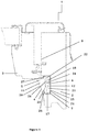
- a section through a roof window indicated generally by the reference numeral 1 having a frame 2, a sash 3 pivotally mounted within the frame 2 and a latch not shown for releasably coupling the sash 3 and frame 2 together in a closed coplanar position.
- the window 1 has a sash movement restriction arrangement 4 mounted on the frame having a movable barrier 5 operable between a locking position as shown in the drawing and an open position by a biasing arrangement 6.
- the movable barrier 5 When the movable barrier 5 is in the locking position, the sash 3 is substantially restricted from moving away from the closed coplanar position.
- the movable barrier 5 When the movable barrier 5 is in the open position, the sash 3 is free to pivot relative to the frame 2 when the latch is in the disengaged position.
- the latch has a locked position for securely coupling the sash 3 and frame 2 together in a coplanar position.
- the latch also has a ventilation position for securely coupling the sash 3 and frame 2 together in a co-planar position allowing air to pass between the frame 2 and the sash 3.
- the latch also has a third disengaged position wherein the frame 2 and sash 3 are decoupled allowing the sash 3 to pivot about the frame 2.
- the sash 3 in unable to pivot away from the closed position when the moveable barrier 5 is in the locking position operating between the sash 3 and the frame 2. This prevents access from the outside by intruders simply pushing a bar through the ventilation gap to open the latch when the latch is in the ventilation position or by simply pushing the sash 3 open if the latch is in the disengaged position.
- the movable barrier 5 is located in the frame 2 partially in a recess 7 formed in the sash facing surface 8 of the frame 2.
- the biasing arrangement 6 is disposed between the frame 2 and the movable barrier 5.
- the biasing arrangement 6 is integrally formed with the movable barrier 5.
- the biasing arrangement 6 and movable barrier 5 are formed as a homogenous one piece component.
- the biasing arrangement 6 is disposed between a recess 7 in the frame 2 and the movable barrier 5.
- the movable barrier 5 allows the sash 3 to move from an open position to a closed position but prevents the sash 3 from moving from a closed position to an open position.
- the movable barrier 5 is movable from a locking position to an open position and back to a locking position by moving the sash 3 past the movable barrier 5 in the direction of closing of the sash 3.
- the movable barrier 5 is movable between a locking position and a closed position by moving the sash 3 past the movable barrier 5 in the direction of closing the sash 3.
- the movable barrier 5 is movable from a locking position to an open position manually by a user.
- the movable barrier 5 protrudes from the recess 7 in the frame in the normally biased condition.
- the movable barrier 5 is in a locking position when the sash 3 is in a closed position thereby inhibiting the movement of the sash 3 unless the movable barrier 5 is manipulated by a user.
- the movable barrier 5 In the open position, the movable barrier 5 is flush with or below the surface of the frame 2.
- the movable barrier 5 has a sash locking member 11 protruding from the recess 7 of the frame 2 and a biasing member 12 located within the recess 7.
- the biasing member 12 has a flexible element 14 mechanically coupled between the sash locking member 11 and the recess 7.
- the flexible element 14 comprises a flexible ramp 14 mechanically coupled to the sash locking member 11.
- the flexible ramp 14 extends along part of the base 15 of the recess 7.
- this allows the ramp 14 to extend along the base 15 of the recess 7 as a result of compression of the ramp 14 due to depression of the sash locking member 11 into the recess 7.
- the flexible ramp 14 has a heel 17 spacing the ramp 14 away from the base 15 of the recess 7, the ramp 14 extending to a toe 18 resting on the base 15 of the recess 7.
- a gap 21 exists between the underside of the flexible ramp 14 and the base 15 of the recess 7.
- the sash locking member 11 is mechanically coupled to the heel 17 of the flexible ramp 14 protruding forward from the heel 17 in a jaw like configuration, defining an expanding mouth 22 between the flexible ramp 14 and the sash locking member 11.
- the mechanical coupling 23 between the sash locking member 11 and the heel 17 of the flexible ramp 14 is also flexible.
- a gap 24 exists between the top of the flexible ramp 14 and a base of the sash locking member 11.
- this gap 24 allows the sash locking member 11 to move in and out of the recess 7 between the locking position and the open position.
- An insert 25 is located in the recess 7 and the insert 25 is an open profile thin walled insert.
- the insert 25 is formed for snug fitting in the recess 7 and has a generally C-Channel cross section.
- the insert 25 and the movable barrier 5 have co-operating retaining members 26, 27 for retaining the movable barrier 5 in the recess 7.
- the insert 25 has two overhang members 26 protruding part of the way across the opening of the insert 25.
- the movable barrier 5 has a sloped contact surface 28 formed for allowing movement of the sash 3 over the sloped surface 28 of the movable barrier 5.
- the sloped surface 28 of the movable barrier 5 is orientated relative to the frame 2 so that closing the sash 3 causes the sash 3 to move in a direction up the sloped surface 28 simultaneously depressing the movable barrier 5 into the recess 7 between the locking position and the open position.
Landscapes
- Engineering & Computer Science (AREA)
- Architecture (AREA)
- Civil Engineering (AREA)
- Structural Engineering (AREA)
- Mechanical Engineering (AREA)
- Specific Sealing Or Ventilating Devices For Doors And Windows (AREA)
- Wing Frames And Configurations (AREA)
Applications Claiming Priority (2)
| Application Number | Priority Date | Filing Date | Title |
|---|---|---|---|
| GB201222087 | 2012-12-07 | ||
| EP13196336.5A EP2740853B1 (fr) | 2012-12-07 | 2013-12-09 | Fenêtre de toit avec dispositif de verrouillage |
Related Parent Applications (1)
| Application Number | Title | Priority Date | Filing Date |
|---|---|---|---|
| EP13196336.5A Division EP2740853B1 (fr) | 2012-12-07 | 2013-12-09 | Fenêtre de toit avec dispositif de verrouillage |
Publications (1)
| Publication Number | Publication Date |
|---|---|
| EP3216939A1 true EP3216939A1 (fr) | 2017-09-13 |
Family
ID=49911130
Family Applications (2)
| Application Number | Title | Priority Date | Filing Date |
|---|---|---|---|
| EP17159654.7A Withdrawn EP3216939A1 (fr) | 2012-12-07 | 2013-12-09 | Fenêtre de toit avec dispositif de verrouillage |
| EP13196336.5A Active EP2740853B1 (fr) | 2012-12-07 | 2013-12-09 | Fenêtre de toit avec dispositif de verrouillage |
Family Applications After (1)
| Application Number | Title | Priority Date | Filing Date |
|---|---|---|---|
| EP13196336.5A Active EP2740853B1 (fr) | 2012-12-07 | 2013-12-09 | Fenêtre de toit avec dispositif de verrouillage |
Country Status (2)
| Country | Link |
|---|---|
| EP (2) | EP3216939A1 (fr) |
| PL (1) | PL2740853T3 (fr) |
Families Citing this family (1)
| Publication number | Priority date | Publication date | Assignee | Title |
|---|---|---|---|---|
| PL248508B1 (pl) | 2022-05-18 | 2025-12-22 | Fakro Pp Spolka Z Ograniczona Odpowiedzialnoscia | Rama okienna z profilem wypełniającym |
Citations (6)
| Publication number | Priority date | Publication date | Assignee | Title |
|---|---|---|---|---|
| JPS56159529U (fr) * | 1980-04-28 | 1981-11-27 | ||
| GB2233701A (en) * | 1989-06-29 | 1991-01-16 | Uniqey | Door lock |
| GB2283275A (en) * | 1993-10-29 | 1995-05-03 | John Harold Jonas | Door catch |
| US6021606A (en) * | 1998-10-01 | 2000-02-08 | The Bilco Company | Lifting mechanism for horizontal hinged doors |
| WO2004018812A1 (fr) * | 2002-08-16 | 2004-03-04 | Vkr Holding A/S | Dispositif de verrouillage de fenetre |
| EP2157262A1 (fr) * | 2008-08-19 | 2010-02-24 | T.J.de Rooij Wood Desing | Sécurité anti-cambriolage pour tabatière |
-
2013
- 2013-12-09 EP EP17159654.7A patent/EP3216939A1/fr not_active Withdrawn
- 2013-12-09 EP EP13196336.5A patent/EP2740853B1/fr active Active
- 2013-12-09 PL PL13196336T patent/PL2740853T3/pl unknown
Patent Citations (6)
| Publication number | Priority date | Publication date | Assignee | Title |
|---|---|---|---|---|
| JPS56159529U (fr) * | 1980-04-28 | 1981-11-27 | ||
| GB2233701A (en) * | 1989-06-29 | 1991-01-16 | Uniqey | Door lock |
| GB2283275A (en) * | 1993-10-29 | 1995-05-03 | John Harold Jonas | Door catch |
| US6021606A (en) * | 1998-10-01 | 2000-02-08 | The Bilco Company | Lifting mechanism for horizontal hinged doors |
| WO2004018812A1 (fr) * | 2002-08-16 | 2004-03-04 | Vkr Holding A/S | Dispositif de verrouillage de fenetre |
| EP2157262A1 (fr) * | 2008-08-19 | 2010-02-24 | T.J.de Rooij Wood Desing | Sécurité anti-cambriolage pour tabatière |
Also Published As
| Publication number | Publication date |
|---|---|
| EP2740853B1 (fr) | 2017-03-08 |
| PL2740853T3 (pl) | 2017-09-29 |
| EP2740853A1 (fr) | 2014-06-11 |
Similar Documents
| Publication | Publication Date | Title |
|---|---|---|
| US8272164B2 (en) | Double hung sash lock with tilt lock release buttons | |
| US11371263B2 (en) | Latch arrangement having a stop latch | |
| EP3423652B1 (fr) | Agencement de verrou ayant une poignée | |
| US20080030028A1 (en) | Reach Out Lock | |
| US9670691B2 (en) | Continuous handle for window | |
| US20080115545A1 (en) | Door panel integrated door stopper with operating mechanism integrated into the door lock housing | |
| NZ233276A (en) | Latching window stay | |
| JP2001115719A (ja) | 錠止可能な回転及び/又はスライド・ウイングシステム | |
| CN101657596A (zh) | 铰链装置 | |
| US10844650B2 (en) | Emergency exit window system | |
| EP3216939A1 (fr) | Fenêtre de toit avec dispositif de verrouillage | |
| US8136300B2 (en) | Window or door frame having brace device | |
| US9260893B1 (en) | Window lock | |
| GB2391901A (en) | Lockable stay | |
| JP2009243146A (ja) | サッシ用錠装置 | |
| EP2937496B1 (fr) | Fonctionnement de poignée pour porte pliable/coulissante | |
| US20070029817A1 (en) | Safety lock | |
| JP2017214708A (ja) | 開き扉の施解錠機構 | |
| EP2310592B1 (fr) | Dispositif de verrouillage pour fenêtre de toit | |
| US1046833A (en) | Combined window lock and ventilator. | |
| CN100510302C (zh) | 锁装置及门窗设备 | |
| AU2021290420B2 (en) | A latch assembly | |
| JP5300284B2 (ja) | 扉装置 | |
| KR200418405Y1 (ko) | 창문 잠김장치 | |
| EP1749960A1 (fr) | Assemblage coulissante et pivotante et dispositif de fermeture et d'ouverture |
Legal Events
| Date | Code | Title | Description |
|---|---|---|---|
| PUAI | Public reference made under article 153(3) epc to a published international application that has entered the european phase |
Free format text: ORIGINAL CODE: 0009012 |
|
| STAA | Information on the status of an ep patent application or granted ep patent |
Free format text: STATUS: THE APPLICATION HAS BEEN PUBLISHED |
|
| AC | Divisional application: reference to earlier application |
Ref document number: 2740853 Country of ref document: EP Kind code of ref document: P |
|
| AK | Designated contracting states |
Kind code of ref document: A1 Designated state(s): AL AT BE BG CH CY CZ DE DK EE ES FI FR GB GR HR HU IE IS IT LI LT LU LV MC MK MT NL NO PL PT RO RS SE SI SK SM TR |
|
| STAA | Information on the status of an ep patent application or granted ep patent |
Free format text: STATUS: REQUEST FOR EXAMINATION WAS MADE |
|
| 17P | Request for examination filed |
Effective date: 20180313 |
|
| RBV | Designated contracting states (corrected) |
Designated state(s): AL AT BE BG CH CY CZ DE DK EE ES FI FR GB GR HR HU IE IS IT LI LT LU LV MC MK MT NL NO PL PT RO RS SE SI SK SM TR |
|
| STAA | Information on the status of an ep patent application or granted ep patent |
Free format text: STATUS: EXAMINATION IS IN PROGRESS |
|
| 17Q | First examination report despatched |
Effective date: 20190205 |
|
| GRAP | Despatch of communication of intention to grant a patent |
Free format text: ORIGINAL CODE: EPIDOSNIGR1 |
|
| STAA | Information on the status of an ep patent application or granted ep patent |
Free format text: STATUS: GRANT OF PATENT IS INTENDED |
|
| INTG | Intention to grant announced |
Effective date: 20210114 |
|
| STAA | Information on the status of an ep patent application or granted ep patent |
Free format text: STATUS: THE APPLICATION IS DEEMED TO BE WITHDRAWN |
|
| 18D | Application deemed to be withdrawn |
Effective date: 20210526 |