EP3217018B1 - Propellerlüfter, propellerlüftervorrichtung und ausseneinheit für klimaanlage - Google Patents
Propellerlüfter, propellerlüftervorrichtung und ausseneinheit für klimaanlage Download PDFInfo
- Publication number
- EP3217018B1 EP3217018B1 EP14905593.1A EP14905593A EP3217018B1 EP 3217018 B1 EP3217018 B1 EP 3217018B1 EP 14905593 A EP14905593 A EP 14905593A EP 3217018 B1 EP3217018 B1 EP 3217018B1
- Authority
- EP
- European Patent Office
- Prior art keywords
- propeller fan
- protrusion
- blade
- air
- airflow velocity
- Prior art date
- Legal status (The legal status is an assumption and is not a legal conclusion. Google has not performed a legal analysis and makes no representation as to the accuracy of the status listed.)
- Active
Links
Images




Classifications
-
- F—MECHANICAL ENGINEERING; LIGHTING; HEATING; WEAPONS; BLASTING
- F04—POSITIVE - DISPLACEMENT MACHINES FOR LIQUIDS; PUMPS FOR LIQUIDS OR ELASTIC FLUIDS
- F04D—NON-POSITIVE-DISPLACEMENT PUMPS
- F04D29/00—Details, component parts, or accessories
- F04D29/26—Rotors specially for elastic fluids
- F04D29/32—Rotors specially for elastic fluids for axial flow pumps
- F04D29/38—Blades
- F04D29/384—Blades characterised by form
-
- F—MECHANICAL ENGINEERING; LIGHTING; HEATING; WEAPONS; BLASTING
- F04—POSITIVE - DISPLACEMENT MACHINES FOR LIQUIDS; PUMPS FOR LIQUIDS OR ELASTIC FLUIDS
- F04D—NON-POSITIVE-DISPLACEMENT PUMPS
- F04D29/00—Details, component parts, or accessories
- F04D29/66—Combating cavitation, whirls, noise, vibration or the like; Balancing
- F04D29/661—Combating cavitation, whirls, noise, vibration or the like; Balancing especially adapted for elastic fluid pumps
- F04D29/667—Combating cavitation, whirls, noise, vibration or the like; Balancing especially adapted for elastic fluid pumps by influencing the flow pattern, e.g. suppression of turbulence
-
- F—MECHANICAL ENGINEERING; LIGHTING; HEATING; WEAPONS; BLASTING
- F05—INDEXING SCHEMES RELATING TO ENGINES OR PUMPS IN VARIOUS SUBCLASSES OF CLASSES F01-F04
- F05D—INDEXING SCHEME FOR ASPECTS RELATING TO NON-POSITIVE-DISPLACEMENT MACHINES OR ENGINES, GAS-TURBINES OR JET-PROPULSION PLANTS
- F05D2240/00—Components
- F05D2240/20—Rotors
- F05D2240/30—Characteristics of rotor blades, i.e. of any element transforming dynamic fluid energy to or from rotational energy and being attached to a rotor
- F05D2240/303—Characteristics of rotor blades, i.e. of any element transforming dynamic fluid energy to or from rotational energy and being attached to a rotor related to the leading edge of a rotor blade
-
- F—MECHANICAL ENGINEERING; LIGHTING; HEATING; WEAPONS; BLASTING
- F05—INDEXING SCHEMES RELATING TO ENGINES OR PUMPS IN VARIOUS SUBCLASSES OF CLASSES F01-F04
- F05D—INDEXING SCHEME FOR ASPECTS RELATING TO NON-POSITIVE-DISPLACEMENT MACHINES OR ENGINES, GAS-TURBINES OR JET-PROPULSION PLANTS
- F05D2240/00—Components
- F05D2240/20—Rotors
- F05D2240/30—Characteristics of rotor blades, i.e. of any element transforming dynamic fluid energy to or from rotational energy and being attached to a rotor
- F05D2240/304—Characteristics of rotor blades, i.e. of any element transforming dynamic fluid energy to or from rotational energy and being attached to a rotor related to the trailing edge of a rotor blade
Definitions
- the present invention relates to a propeller fan, a propeller fan apparatus, and an outdoor unit for an air conditioning apparatus.
- Related-art propeller fan shapes may include a propeller fan shape as disclosed in Japanese Patent No. 2590514 (page 7, FIG. 9 ).
- a blade mounting angle ⁇ gradually decreases from a blade root portion to a blade intermediate portion, and the blade mounting angle ⁇ increases from the blade intermediate portion to a blade distal edge.
- the blade mounting angle ⁇ at the blade distal edge is set large to increase axial velocity at the blade distal edge, thereby achieving the suppression of turbulence of air at the distal edge and reduction of noise.
- the blade mounting angle ⁇ is set large at the blade root portion to secure a high airflow rate.
- Patent Literature 1 With the technology disclosed in Patent Literature 1, an airflow velocity distribution on downstream of the fan is not equalized, with the result that a region having a high airflow velocity is locally formed. Thus, there has been a problem in that noise is increased when a structure such as a grille is present on downstream of the fan.
- the present invention has been made to solve the problem described above, and has an object to provide a propeller fan which is reduced in noise.
- a propeller fan as set forth in claim 1. Further, in order to achieve the same object, there is provided a propeller fan apparatus as set forth in claim 4.
- the propeller fan which is reduced in noise can be provided.
- FIG. 1 is a front view of an outdoor unit for an air conditioning apparatus according to a first embodiment of the present invention.
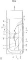
- FIG. 2 is a plan view of an internal configuration of the outdoor unit for an air conditioning apparatus according to the first embodiment of the present invention.
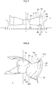
- FIG. 3 is a perspective view of a propeller fan according to the first embodiment of the present invention.
- an outdoor unit 100 for an air conditioning apparatus includes a case 51.
- the case 51 is configured as a housing which has a pair of left and right side surfaces 51a and 51c, a front surface 51b, a back surface 51d, a top surface 51e, and a bottom surface 51f.
- the side surface 51a and the back surface 51d have opening portions for taking air from outside (see the arrows A).
- the front surface 51b has an air outlet being an opening portion for blowing air to outside (see the arrows A).
- the air outlet is covered with a lattice-shaped fan grille 4.
- a propeller fan 1 In the case 51 of the outdoor unit 100 for an air conditioning apparatus, there are accommodated a propeller fan 1, a fan motor (drive source) 61, a bellmouth 3, and a heat exchanger 68.
- the propeller fan 1, as one example, is connected to the fan motor 61 which is arranged on the back surface 51d side with respect to the propeller fan 1, and is rotated by a driving force of the fan motor 61.
- the heat exchanger 68 is arranged in the vicinity of the side surface 51a and the back surface 51d, and extends to form a substantially L-shape in plan view along the side surface 51a and the back surface 51d.
- the bellmouth 3 On a radially outer side of the propeller fan 1, the bellmouth 3 is arranged.
- the bellmouth 3 forms a loop shape or a ring shape along a rotation direction of the propeller fan 1.
- the arrows A in FIG. 2 and FIG. 3 exemplify a flow of air.
- the arrows A are mere examples for illustration, and do not accurately represent an actual flow.
- the propeller fan 1 includes a boss 1a and a plurality of blades 2. As one example, in the first embodiment, the propeller fan 1 includes three blades 2.
- the boss 1a forms a center portion of the propeller fan 1.
- a rotation center line RC of the propeller fan 1 extends through the boss 1a.
- the shape of the boss 1a is not particularly limited, and may be formed into, for example, a columnar shape or a conical shape.
- the three blades 2 are fixed to an outer peripheral surface of the boss 1a.
- the blades 2 are partially surrounded by the bellmouth 3 in plan view. That is, respective downstream portions of the blades 2 are located, in plan view, within an inner region of the bellmouth 3 which is surrounded by the bellmouth 3, and respective upstream portions of the blades 2 are located, in plan view, outside the inner region of the bellmouth 3 which is surrounded by the bellmouth 3. That is, the respective upstream portions of the blades 2 are located on upstream of an upstream end, which is an inlet end, of the bellmouth 3.
- the fan grille 4 is arranged on downstream of the propeller fan 1.
- the three blades 2 have the same shape, though not particularly limited. Thus, description is made of one blade 2.
- the blade has, as extending from an inner peripheral edge 23 to an outer peripheral edge 24 in a radial direction of the blade, at least one of a shape in which a part of a leading edge 21 protrudes toward a positive pressure surface 2a side, or a shape in which a part of a trailing edge 22 protrudes toward a negative pressure surface 2b side.
- the blade 2 has, as extending from an innermost periphery to an outermost periphery in the radial direction, at least one of a shape in which the leading edge 21 locally protrudes toward the positive pressure surface 2a side, or a shape in which the trailing edge 22 locally protrudes toward the negative pressure surface 2b side.
- the blade 2 of the illustrated example has both the shape in which a part of the leading edge 21 protrudes toward the positive pressure surface 2a side and the shape in which a part of the trailing edge 22 protrudes toward the negative pressure surface 2b side.
- the above-mentioned protrusion at a part of the leading edge 21 is a protrusion toward downstream in the air-blowing direction
- the above-mentioned protrusion at a part of the trailing edge 22 is a protrusion toward upstream in the air-blowing direction.
- a center 28 of the protrusion at the leading edge 21 in the radial direction and a center 28 of the protrusion at the trailing edge 22 in the radial direction are located on a radially outer side with respect to a radial position of 0.5Rt from the rotation center line RC, that is, located on a radially outer side with respect to a radial position at a half of the blade radius from the rotation center line RC.
- Each of the center 28 of the protrusion at the leading edge 21 in the radial direction and the center 28 of the protrusion at the trailing edge 22 in the radial direction represents a central position in the radial direction between a protrusion-start radial position 26, which is an innermost position of the protrusion in the radial direction, and a protrusion-end radial position 27, which is an outermost position of the protrusion in the radial direction.
- both a partial leading edge-side protrusion area 31, which starts from the above-mentioned protrusion at a part 21a of the leading edge 21, and a partial trailing edge-side protrusion area 32, which starts from the above-mentioned protrusion at a part 22a of the trailing edge 22, extend in front-back direction of a rotation trajectory.
- a protrusion height of the partial leading edge-side protrusion area 31, which starts from the protrusion at the part 21a of the leading edge 21, is maximum at the leading edge 21 and gradually decreases toward the trailing edge 22.
- a protrusion height of the partial trailing edge-side protrusion area 32, which starts from the protrusion at the part 22a of the trailing edge 22, is maximum at the trailing edge 22 and gradually decreases toward the leading edge 21.
- a curved line of a blade surface connecting the leading edge 21 or the part 21a to the trailing edge 22 or the part 22a has a substantially arc shape.
- FIG. 4 is an illustration of a blowing airflow velocity distribution of a propeller fan according to a comparison example.
- FIG. 5 is an illustration of a blowing airflow velocity distribution of the propeller fan according to the present invention.
- FIG. 6 is a graph for showing the blowing airflow velocity distribution of the propeller fan according to the present invention.
- the blowing airflow velocity distribution of the propeller fan including only blades 2' each having neither the leading edge-side protrusion area 31 nor the trailing edge-side protrusion area 32 described above exhibits the airflow velocity distribution in which, as illustrated in FIG. 4 , the airflow velocity is maximum in the vicinity of the outer peripheral edge 24 of the blade 2' .
- the airflow velocity gradually increases from the inner peripheral edge 23 toward the outer peripheral edge 24 of the blade 2' because the movement velocity of the blade 2' is higher on the outer peripheral side of the blade 2' to increase the amount of work of the blade 2'.
- the airflow velocity decreases at the outermost part in the vicinity of the outer peripheral edge 24 because there is leakage through a clearance between the blade 2' and the bellmouth 3 at the outer peripheral edge 24 of the blade 2' or because the amount of work is originally small due to protrusion at a part of the blade 2' on upstream in the air-blowing direction from the bellmouth 3.
- the above-mentioned configuration of the propeller fan 1 according to the first embodiment of the present invention reduces the velocity component in the turning direction in the region having the maximum airflow velocity in the blowing airflow velocity distribution from the propeller fan 1, thereby being capable of effectively decreasing the amount of work of the blade 2 and relatively increasing the amount of work of the blade 2 at the inner peripheral edge 23.
- more equalized blowing airflow velocity distribution can be achieved in the radial direction of the blade 2 so that the noise which is generated when the air stream passes through the fan grille 4 arranged on downstream of the propeller fan 1 is reduced, thereby being capable of reducing noise of the propeller fan.
- the curved line of the blade surface connecting the leading edge 21 or the part 21a to the trailing edge 22 or the part 22a has the substantially arc shape.
- the propeller fan according to the comparison example and the propeller fan 1 according to the first embodiment of the present invention are compared.
- an apparent maximum portion of the airflow velocity can be seen near a radius ratio of 0.8.
- the airflow velocity near the radius ratio of 0.8 is reduced as compared to the case of the propeller fan according to the comparison example.
- the airflow velocity in the region at the radius ratio of 0.6 or less on an inner peripheral side of the blade is increased as compared to the case of the propeller fan according to the comparison example.
- the radius ratio is a ratio of a radial position on the blade when the blade radius Rt, which is a radius of the propeller fan, is 1.
- the normalized airflow velocity is the airflow velocity which is normalized when a maximum value of the blowing airflow velocity distribution of the propeller fan according to the comparison example is 1.
- a propeller fan and an outdoor unit for an air conditioning apparatus which are reduced in noise can be provided.
- FIG. 7 is a plan view for illustrating a propeller fan and a periphery thereof according to the second embodiment of the present invention.
- details other than those described below are the same as the details of the above-mentioned first embodiment.
- maximum protrusion radial positions 25 of the protrusion at the leading edge 21 and the protrusion at the trailing edge 22 are located on an outer side in the radial direction with respect to a radial position of the centers 28 of the protrusions in the radial direction between the protrusion-start radial position 26 and the protrusion-end radial position 27.
- FIG. 7 is a plan view for illustrating a propeller fan and a periphery thereof according to the third embodiment of the present invention.
- details other than those described below are the same as the details of the first embodiment or the second embodiment described above.
- the maximum protrusion radial positions 25 of the protrusion at the leading edge 21 and the protrusion at the trailing edge 22 are located on the outer side in the radial direction with respect to the radial position of the centers 28 of the protrusions in the radial direction between the protrusion-start radial position 26 and the protrusion-end radial position 27.
- the maximum protrusion radial positions 25 of the protrusion at the leading edge 21 and the protrusion at the trailing edge 22 are arranged at positions substantially matching with the maximum portion of the blowing airflow velocity distribution. That is, when the maximum protrusion radial positions 25 are to be set, the blowing airflow velocity distribution is obtained with regard to a blade which is different only in condition that the protrusion is arranged neither at the leading edge nor at the trailing edge. Then, the maximum protrusion radial positions 25 are set at positions of the maximum portion of the blowing airflow velocity distribution. Specifically, as described above in relation to FIG.
- the blowing airflow velocity distribution of the propeller fan according to the comparison example has a maximum portion of the airflow velocity distribution near the radius ratio of 0.8, which is a radial position at 0.8Rt from the rotation center line RC.
- the maximum protrusion radial positions 25 of the protrusion at the leading edge 21 and the protrusion at the trailing edge 22 are arranged at the radial positions of 0.8Rt from the rotation center line RC.
- the airflow velocity can be reduced at most.
- the positions at which the airflow velocity is reduced at most are set so as to substantially match with the maximum portion of the blowing airflow velocity distribution of the propeller fan 1.
- the blowing airflow velocity distribution of the propeller fan 1 can be further equalized, and the noise which is generated when the air stream passes through the fan grille 4 arranged on downstream of the propeller fan 1 is reduced, thereby being capable of reducing noise of the propeller fan.
- FIG. 8 is a perspective view of a propeller fan according to the fourth embodiment of the present invention.
- FIG. 9 is a graph for showing L/Rt and a maximum value of a normalized airflow velocity of the propeller fan according to the fourth embodiment of the present invention.
- details other than those described below are the same as the details of any one of the first embodiment, the second embodiment, and the third embodiment described above.
- a protrusion height L of the maximum protrusion radial positions 25 of the protrusion at the leading edge 21 and the protrusion at the trailing edge 22 of the blade 2 is set so as to satisfy L/Rt ⁇ 0.1.
- the relative velocity of the air stream which flows along the blade surface is increased.
- Such an increase in relative velocity may become a factor of increasing the noise.
- the maximum value of the normalized airflow velocity is constant.
- the factor of increasing the noise may be dominant.
- the protrusion is formed so as to satisfy L/Rt ⁇ 0.1 as described above.
- the propeller fan incorporated into an outdoor unit for an air conditioning apparatus.
- the propeller fan according to the present invention is not limited thereto.
- the present invention can be carried out as a propeller fan apparatus including the propeller fan, the bellmouth, and the fan grille, which are described above.
- the bellmouth surrounds a portion of the propeller fan on downstream in the air-blowing direction in plan view, and a portion of the propeller fan on upstream in the air-blowing direction is arranged outside the bellmouth in plan view.
- the fan grille is arranged on downstream of the propeller fan in the air-blowing direction.
- the propeller fan apparatus can be used for a refrigeration cycle system (system with a refrigeration circuit including at least a compressor, a condenser, an expansion device, and an evaporator) such as a refrigeration apparatus other than the air conditioning apparatus.
- the propeller fan apparatus can also be used for a ventilation device, an air-sending device, and a drier, which do not require employment of a heat-exchanging element.
- the case where three blades are arranged is illustrated as the preferred mode of carrying out the present invention.
- the present invention can also be carried out with the number of blades other than three. Also with such a configuration, the above-mentioned advantageous actions and effects can be obtained.
- illustration is made of the mode in which the blade has both the shape in which a part of the leading edge protrudes toward the positive pressure surface side and the shape in which a part of the trailing edge protrudes toward the negative pressure surface side.
- this mode is a mere example of the present invention.
- the blade in relation to the present invention may be in a mode of having the protrusion at the leading edge and no protrusion at the trailing edge, or in a mode of having the protrusion at the trailing edge and no protrusion at the leading edge.
Landscapes
- Engineering & Computer Science (AREA)
- Mechanical Engineering (AREA)
- General Engineering & Computer Science (AREA)
- Structures Of Non-Positive Displacement Pumps (AREA)
- Air-Conditioning Room Units, And Self-Contained Units In General (AREA)
- Other Air-Conditioning Systems (AREA)
Claims (5)
- Propellerlüfter (1), der Folgendes umfasst:eine Nabe (1a) undein an der Nabe (1a) befestigtes Blatt (2),wobei das Blatt (2) eine aus einer Form, in der ein Teil einer Vorderkante (21) des Blatts (2) in Richtung einer Seite einer Überdruckfläche (2a) vorsteht, und einer Form, in der ein Teil einer Hinterkante (22) des Blatts (2) in Richtung einer Seite einer Unterdruckfläche (2b) vorsteht, aufweist,wobei ein Mittelpunkt eines Vorsprungs in radialer Richtung des Blatts (2) auf einer radial äußeren Seite in Bezug auf eine radiale Position in der Hälfte des Blattradius von einer Rotationsmittellinie angeordnet ist, dadurch gekennzeichnet, dassdie maximale radiale Vorsprungposition des Vorsprungs auf einer radial äußeren Seite in Bezug auf eine radiale Position des Mittelpunkts des Vorsprungs in radialer Richtung angeordnet ist.
- Propellerlüfter (1) nach Anspruch 1,
wobei der Lüfter eine Blasluftstromgeschwindigkeitsverteilung aufweist und
wobei die maximale radiale Vorsprungposition an einer Position angeordnet ist, die mit einem Maximalgeschwindigkeitsabschnitt der Blasluftstromgeschwindigkeitsverteilung übereinstimmt. - Propellerlüfter (1) nach Anspruch 1 oder 2,
wobei eine Vorsprunghöhe L des Vorsprungs an der maximalen radialen Vorsprungposition so festgelegt ist, dass gilt: L/Rt<0,1,
worin Rt für einen Blattradius von der Rotationsmittellinie zu einer Außenumfangskante (24) des Blatts (2) steht. - Propellerlüftervorrichtung, die Folgendes umfasst:einen Propellerlüfter (1) nach einem der Ansprüche 1 bis 3;einen Trichter (3) undein Lüftergitter (4),wobei der Trichter (3) einen stromabwärts gelegenen Abschnitt des Propellerlüfters (1) in eine Luftblasrichtung in einer Draufsicht umgibt,wobei ein stromaufwärts gelegener Abschnitt des Propellerlüfters (1) in der Luftblasrichtung in einer Draufsicht an einer Außenseite des Trichters (3) angeordnet ist, undwobei das Lüftergitter (4) stromabwärts in Bezug auf den Propellerlüfter (1) in der Luftblasrichtung angeordnet ist.
- Außeneinheit (100) für eine Klimatisierungsvorrichtung, die einen Propellerlüfter (1) nach einem der Ansprüche 1 bis 3 umfasst.
Applications Claiming Priority (1)
| Application Number | Priority Date | Filing Date | Title |
|---|---|---|---|
| PCT/JP2014/079190 WO2016071948A1 (ja) | 2014-11-04 | 2014-11-04 | プロペラファン、プロペラファン装置および空気調和装置用室外機 |
Publications (3)
| Publication Number | Publication Date |
|---|---|
| EP3217018A1 EP3217018A1 (de) | 2017-09-13 |
| EP3217018A4 EP3217018A4 (de) | 2018-05-30 |
| EP3217018B1 true EP3217018B1 (de) | 2020-09-16 |
Family
ID=55908705
Family Applications (1)
| Application Number | Title | Priority Date | Filing Date |
|---|---|---|---|
| EP14905593.1A Active EP3217018B1 (de) | 2014-11-04 | 2014-11-04 | Propellerlüfter, propellerlüftervorrichtung und ausseneinheit für klimaanlage |
Country Status (3)
| Country | Link |
|---|---|
| EP (1) | EP3217018B1 (de) |
| JP (1) | JP6377172B2 (de) |
| WO (1) | WO2016071948A1 (de) |
Families Citing this family (7)
| Publication number | Priority date | Publication date | Assignee | Title |
|---|---|---|---|---|
| WO2018020708A1 (ja) * | 2016-07-27 | 2018-02-01 | シャープ株式会社 | プロペラファンおよび流体送り装置 |
| JP6849366B2 (ja) * | 2016-09-29 | 2021-03-24 | 山洋電気株式会社 | リバーシブルフローファン |
| USD980965S1 (en) | 2019-05-07 | 2023-03-14 | Carrier Corporation | Leading edge of a fan blade |
| US11187083B2 (en) | 2019-05-07 | 2021-11-30 | Carrier Corporation | HVAC fan |
| US20220186742A1 (en) * | 2019-05-21 | 2022-06-16 | Mitsubishi Electric Corporation | Axial fan, air-sending device, and refrigeration cycle apparatus |
| CN114641619B (zh) * | 2019-11-12 | 2024-10-29 | 三菱电机株式会社 | 轴流风扇、送风装置及制冷循环装置 |
| WO2021192036A1 (ja) * | 2020-03-24 | 2021-09-30 | 三菱電機株式会社 | 軸流ファン、送風装置、及び、冷凍サイクル装置 |
Family Cites Families (15)
| Publication number | Priority date | Publication date | Assignee | Title |
|---|---|---|---|---|
| JPS5818097U (ja) * | 1981-07-30 | 1983-02-03 | 日産デイ−ゼル工業株式会社 | 内燃機関の冷却フアン |
| JPS59165598U (ja) * | 1983-04-20 | 1984-11-06 | 大日本インキ化学工業株式会社 | 送風機 |
| DE9013099U1 (de) * | 1990-09-14 | 1991-11-07 | Moser, Josef, 8058 Pretzen | Rotor |
| JP4501575B2 (ja) * | 2004-07-26 | 2010-07-14 | 三菱電機株式会社 | 軸流送風機 |
| JP4400686B2 (ja) * | 2008-01-07 | 2010-01-20 | ダイキン工業株式会社 | プロペラファン |
| US8128359B2 (en) * | 2009-03-12 | 2012-03-06 | Listan Asia Inc. | Air fan module and a flow directing blade assembly thereof |
| DE102009035689A1 (de) * | 2009-07-30 | 2011-02-03 | Eads Deutschland Gmbh | Fluiddynamisch wirksamer Rotor |
| JP5263198B2 (ja) * | 2010-02-26 | 2013-08-14 | パナソニック株式会社 | 羽根車と送風機及びそれを用いた空気調和機 |
| TWI464328B (zh) * | 2010-11-05 | 2014-12-11 | Delta Electronics Inc | 風扇結構 |
| KR20130039481A (ko) * | 2011-10-12 | 2013-04-22 | 엘지전자 주식회사 | 축류팬 및 공기 조화기 |
| US9249666B2 (en) * | 2011-12-22 | 2016-02-02 | General Electric Company | Airfoils for wake desensitization and method for fabricating same |
| JP5252070B2 (ja) * | 2011-12-28 | 2013-07-31 | ダイキン工業株式会社 | 軸流ファン |
| US20150217851A1 (en) * | 2012-08-16 | 2015-08-06 | Richard Kelso | Wing configuration |
| KR20140136180A (ko) * | 2013-05-20 | 2014-11-28 | 삼성전자주식회사 | 프로펠러 팬 및 이를 구비하는 공기 조화기 |
| FR3023329B1 (fr) * | 2014-07-03 | 2019-08-02 | Safran Aircraft Engines | Stator ondule pour diminuer le bruit cree par l'interaction avec un rotor |
-
2014
- 2014-11-04 EP EP14905593.1A patent/EP3217018B1/de active Active
- 2014-11-04 JP JP2016557365A patent/JP6377172B2/ja active Active
- 2014-11-04 WO PCT/JP2014/079190 patent/WO2016071948A1/ja not_active Ceased
Non-Patent Citations (1)
| Title |
|---|
| None * |
Also Published As
| Publication number | Publication date |
|---|---|
| EP3217018A1 (de) | 2017-09-13 |
| WO2016071948A1 (ja) | 2016-05-12 |
| EP3217018A4 (de) | 2018-05-30 |
| JP6377172B2 (ja) | 2018-08-22 |
| JPWO2016071948A1 (ja) | 2017-05-25 |
Similar Documents
| Publication | Publication Date | Title |
|---|---|---|
| EP3217018B1 (de) | Propellerlüfter, propellerlüftervorrichtung und ausseneinheit für klimaanlage | |
| CN107923410B (zh) | 螺旋桨式风扇、螺旋桨式风扇装置及空气调节装置用室外机 | |
| CN111279085B (zh) | 离心送风机、送风装置、空调装置以及制冷循环装置 | |
| EP3452727B1 (de) | Einlass für axiallüfter | |
| US9829004B2 (en) | Turbo fan and air conditioner | |
| EP3333431B1 (de) | Zentrifugalgebläse, klimatisierungsvorrichtung und kältekreislaufvorrichtung | |
| US10052931B2 (en) | Outdoor cooling unit in vehicle air-conditioning apparatus | |
| US9945391B2 (en) | Diffuser collar | |
| US9739287B2 (en) | Fan and motor assembly and method of assembling | |
| EP3018362B1 (de) | Luftgebläse und ausseneinheit | |
| US9970454B2 (en) | Propeller fan, blower device, and outdoor equipment | |
| EP3372841B1 (de) | Axiallüfter und klimaanlage mit diesem axiallüfter | |
| EP3372839A1 (de) | Gebläse, ausseneinheit und kühlzyklusvorrichtung | |
| US9897108B2 (en) | Propeller fan, air blower, outdoor unit | |
| GB2562395A (en) | Blower and air conditioner employing same | |
| US20190101131A1 (en) | Centrifugal Blower, Air Conditioner, and Refrigeration Cycle Apparatus | |
| US20170008368A1 (en) | Blower | |
| US11187239B2 (en) | Propeller fan, air-sending device, and refrigeration cycle apparatus | |
| JP2014020235A (ja) | 軸流送風機およびこれを用いた空気調和機の室内機 | |
| JP2016160905A (ja) | 遠心ファン | |
| EP3916238A1 (de) | Ventilatorgebläse, innenraumeinheit und klimaanlage | |
| CN110892201A (zh) | 空气调节机 | |
| EP3534015B1 (de) | Propellerlüfter, aussenmaschine und kältekreislaufvorrichtung | |
| WO2018096658A1 (ja) | 送風機、室外機及び冷凍サイクル装置 | |
| CN115704405A (zh) | 用于风机的风圈和空调外机 |
Legal Events
| Date | Code | Title | Description |
|---|---|---|---|
| STAA | Information on the status of an ep patent application or granted ep patent |
Free format text: STATUS: THE INTERNATIONAL PUBLICATION HAS BEEN MADE |
|
| PUAI | Public reference made under article 153(3) epc to a published international application that has entered the european phase |
Free format text: ORIGINAL CODE: 0009012 |
|
| STAA | Information on the status of an ep patent application or granted ep patent |
Free format text: STATUS: REQUEST FOR EXAMINATION WAS MADE |
|
| 17P | Request for examination filed |
Effective date: 20170509 |
|
| AK | Designated contracting states |
Kind code of ref document: A1 Designated state(s): AL AT BE BG CH CY CZ DE DK EE ES FI FR GB GR HR HU IE IS IT LI LT LU LV MC MK MT NL NO PL PT RO RS SE SI SK SM TR |
|
| AX | Request for extension of the european patent |
Extension state: BA ME |
|
| DAX | Request for extension of the european patent (deleted) | ||
| A4 | Supplementary search report drawn up and despatched |
Effective date: 20180502 |
|
| RIC1 | Information provided on ipc code assigned before grant |
Ipc: F04D 29/38 20060101AFI20180424BHEP Ipc: F04D 29/66 20060101ALI20180424BHEP |
|
| GRAP | Despatch of communication of intention to grant a patent |
Free format text: ORIGINAL CODE: EPIDOSNIGR1 |
|
| STAA | Information on the status of an ep patent application or granted ep patent |
Free format text: STATUS: GRANT OF PATENT IS INTENDED |
|
| RIC1 | Information provided on ipc code assigned before grant |
Ipc: F04D 29/66 20060101ALI20200409BHEP Ipc: F04D 29/38 20060101AFI20200409BHEP |
|
| INTG | Intention to grant announced |
Effective date: 20200430 |
|
| GRAS | Grant fee paid |
Free format text: ORIGINAL CODE: EPIDOSNIGR3 |
|
| GRAA | (expected) grant |
Free format text: ORIGINAL CODE: 0009210 |
|
| STAA | Information on the status of an ep patent application or granted ep patent |
Free format text: STATUS: THE PATENT HAS BEEN GRANTED |
|
| AK | Designated contracting states |
Kind code of ref document: B1 Designated state(s): AL AT BE BG CH CY CZ DE DK EE ES FI FR GB GR HR HU IE IS IT LI LT LU LV MC MK MT NL NO PL PT RO RS SE SI SK SM TR |
|
| REG | Reference to a national code |
Ref country code: GB Ref legal event code: FG4D |
|
| REG | Reference to a national code |
Ref country code: CH Ref legal event code: EP |
|
| REG | Reference to a national code |
Ref country code: DE Ref legal event code: R096 Ref document number: 602014070366 Country of ref document: DE |
|
| REG | Reference to a national code |
Ref country code: IE Ref legal event code: FG4D |
|
| REG | Reference to a national code |
Ref country code: AT Ref legal event code: REF Ref document number: 1314388 Country of ref document: AT Kind code of ref document: T Effective date: 20201015 |
|
| PG25 | Lapsed in a contracting state [announced via postgrant information from national office to epo] |
Ref country code: BG Free format text: LAPSE BECAUSE OF FAILURE TO SUBMIT A TRANSLATION OF THE DESCRIPTION OR TO PAY THE FEE WITHIN THE PRESCRIBED TIME-LIMIT Effective date: 20201216 Ref country code: HR Free format text: LAPSE BECAUSE OF FAILURE TO SUBMIT A TRANSLATION OF THE DESCRIPTION OR TO PAY THE FEE WITHIN THE PRESCRIBED TIME-LIMIT Effective date: 20200916 Ref country code: FI Free format text: LAPSE BECAUSE OF FAILURE TO SUBMIT A TRANSLATION OF THE DESCRIPTION OR TO PAY THE FEE WITHIN THE PRESCRIBED TIME-LIMIT Effective date: 20200916 Ref country code: SE Free format text: LAPSE BECAUSE OF FAILURE TO SUBMIT A TRANSLATION OF THE DESCRIPTION OR TO PAY THE FEE WITHIN THE PRESCRIBED TIME-LIMIT Effective date: 20200916 Ref country code: GR Free format text: LAPSE BECAUSE OF FAILURE TO SUBMIT A TRANSLATION OF THE DESCRIPTION OR TO PAY THE FEE WITHIN THE PRESCRIBED TIME-LIMIT Effective date: 20201217 Ref country code: NO Free format text: LAPSE BECAUSE OF FAILURE TO SUBMIT A TRANSLATION OF THE DESCRIPTION OR TO PAY THE FEE WITHIN THE PRESCRIBED TIME-LIMIT Effective date: 20201216 |
|
| REG | Reference to a national code |
Ref country code: AT Ref legal event code: MK05 Ref document number: 1314388 Country of ref document: AT Kind code of ref document: T Effective date: 20200916 |
|
| REG | Reference to a national code |
Ref country code: NL Ref legal event code: MP Effective date: 20200916 |
|
| PG25 | Lapsed in a contracting state [announced via postgrant information from national office to epo] |
Ref country code: RS Free format text: LAPSE BECAUSE OF FAILURE TO SUBMIT A TRANSLATION OF THE DESCRIPTION OR TO PAY THE FEE WITHIN THE PRESCRIBED TIME-LIMIT Effective date: 20200916 Ref country code: LV Free format text: LAPSE BECAUSE OF FAILURE TO SUBMIT A TRANSLATION OF THE DESCRIPTION OR TO PAY THE FEE WITHIN THE PRESCRIBED TIME-LIMIT Effective date: 20200916 |
|
| REG | Reference to a national code |
Ref country code: LT Ref legal event code: MG4D |
|
| PG25 | Lapsed in a contracting state [announced via postgrant information from national office to epo] |
Ref country code: EE Free format text: LAPSE BECAUSE OF FAILURE TO SUBMIT A TRANSLATION OF THE DESCRIPTION OR TO PAY THE FEE WITHIN THE PRESCRIBED TIME-LIMIT Effective date: 20200916 Ref country code: RO Free format text: LAPSE BECAUSE OF FAILURE TO SUBMIT A TRANSLATION OF THE DESCRIPTION OR TO PAY THE FEE WITHIN THE PRESCRIBED TIME-LIMIT Effective date: 20200916 Ref country code: SM Free format text: LAPSE BECAUSE OF FAILURE TO SUBMIT A TRANSLATION OF THE DESCRIPTION OR TO PAY THE FEE WITHIN THE PRESCRIBED TIME-LIMIT Effective date: 20200916 Ref country code: PT Free format text: LAPSE BECAUSE OF FAILURE TO SUBMIT A TRANSLATION OF THE DESCRIPTION OR TO PAY THE FEE WITHIN THE PRESCRIBED TIME-LIMIT Effective date: 20210118 Ref country code: LT Free format text: LAPSE BECAUSE OF FAILURE TO SUBMIT A TRANSLATION OF THE DESCRIPTION OR TO PAY THE FEE WITHIN THE PRESCRIBED TIME-LIMIT Effective date: 20200916 Ref country code: CZ Free format text: LAPSE BECAUSE OF FAILURE TO SUBMIT A TRANSLATION OF THE DESCRIPTION OR TO PAY THE FEE WITHIN THE PRESCRIBED TIME-LIMIT Effective date: 20200916 |
|
| PG25 | Lapsed in a contracting state [announced via postgrant information from national office to epo] |
Ref country code: ES Free format text: LAPSE BECAUSE OF FAILURE TO SUBMIT A TRANSLATION OF THE DESCRIPTION OR TO PAY THE FEE WITHIN THE PRESCRIBED TIME-LIMIT Effective date: 20200916 Ref country code: AL Free format text: LAPSE BECAUSE OF FAILURE TO SUBMIT A TRANSLATION OF THE DESCRIPTION OR TO PAY THE FEE WITHIN THE PRESCRIBED TIME-LIMIT Effective date: 20200916 Ref country code: AT Free format text: LAPSE BECAUSE OF FAILURE TO SUBMIT A TRANSLATION OF THE DESCRIPTION OR TO PAY THE FEE WITHIN THE PRESCRIBED TIME-LIMIT Effective date: 20200916 Ref country code: PL Free format text: LAPSE BECAUSE OF FAILURE TO SUBMIT A TRANSLATION OF THE DESCRIPTION OR TO PAY THE FEE WITHIN THE PRESCRIBED TIME-LIMIT Effective date: 20200916 Ref country code: IS Free format text: LAPSE BECAUSE OF FAILURE TO SUBMIT A TRANSLATION OF THE DESCRIPTION OR TO PAY THE FEE WITHIN THE PRESCRIBED TIME-LIMIT Effective date: 20210116 |
|
| REG | Reference to a national code |
Ref country code: DE Ref legal event code: R119 Ref document number: 602014070366 Country of ref document: DE |
|
| PG25 | Lapsed in a contracting state [announced via postgrant information from national office to epo] |
Ref country code: MC Free format text: LAPSE BECAUSE OF FAILURE TO SUBMIT A TRANSLATION OF THE DESCRIPTION OR TO PAY THE FEE WITHIN THE PRESCRIBED TIME-LIMIT Effective date: 20200916 Ref country code: SK Free format text: LAPSE BECAUSE OF FAILURE TO SUBMIT A TRANSLATION OF THE DESCRIPTION OR TO PAY THE FEE WITHIN THE PRESCRIBED TIME-LIMIT Effective date: 20200916 |
|
| REG | Reference to a national code |
Ref country code: CH Ref legal event code: PL |
|
| PLBE | No opposition filed within time limit |
Free format text: ORIGINAL CODE: 0009261 |
|
| STAA | Information on the status of an ep patent application or granted ep patent |
Free format text: STATUS: NO OPPOSITION FILED WITHIN TIME LIMIT |
|
| PG25 | Lapsed in a contracting state [announced via postgrant information from national office to epo] |
Ref country code: LU Free format text: LAPSE BECAUSE OF NON-PAYMENT OF DUE FEES Effective date: 20201104 |
|
| REG | Reference to a national code |
Ref country code: BE Ref legal event code: MM Effective date: 20201130 |
|
| 26N | No opposition filed |
Effective date: 20210617 |
|
| PG25 | Lapsed in a contracting state [announced via postgrant information from national office to epo] |
Ref country code: SI Free format text: LAPSE BECAUSE OF FAILURE TO SUBMIT A TRANSLATION OF THE DESCRIPTION OR TO PAY THE FEE WITHIN THE PRESCRIBED TIME-LIMIT Effective date: 20200916 Ref country code: LI Free format text: LAPSE BECAUSE OF NON-PAYMENT OF DUE FEES Effective date: 20201130 Ref country code: CH Free format text: LAPSE BECAUSE OF NON-PAYMENT OF DUE FEES Effective date: 20201130 Ref country code: DK Free format text: LAPSE BECAUSE OF FAILURE TO SUBMIT A TRANSLATION OF THE DESCRIPTION OR TO PAY THE FEE WITHIN THE PRESCRIBED TIME-LIMIT Effective date: 20200916 |
|
| PG25 | Lapsed in a contracting state [announced via postgrant information from national office to epo] |
Ref country code: IE Free format text: LAPSE BECAUSE OF NON-PAYMENT OF DUE FEES Effective date: 20201104 Ref country code: IT Free format text: LAPSE BECAUSE OF FAILURE TO SUBMIT A TRANSLATION OF THE DESCRIPTION OR TO PAY THE FEE WITHIN THE PRESCRIBED TIME-LIMIT Effective date: 20200916 |
|
| PG25 | Lapsed in a contracting state [announced via postgrant information from national office to epo] |
Ref country code: DE Free format text: LAPSE BECAUSE OF NON-PAYMENT OF DUE FEES Effective date: 20210601 |
|
| PG25 | Lapsed in a contracting state [announced via postgrant information from national office to epo] |
Ref country code: IS Free format text: LAPSE BECAUSE OF FAILURE TO SUBMIT A TRANSLATION OF THE DESCRIPTION OR TO PAY THE FEE WITHIN THE PRESCRIBED TIME-LIMIT Effective date: 20210116 Ref country code: TR Free format text: LAPSE BECAUSE OF FAILURE TO SUBMIT A TRANSLATION OF THE DESCRIPTION OR TO PAY THE FEE WITHIN THE PRESCRIBED TIME-LIMIT Effective date: 20200916 Ref country code: MT Free format text: LAPSE BECAUSE OF FAILURE TO SUBMIT A TRANSLATION OF THE DESCRIPTION OR TO PAY THE FEE WITHIN THE PRESCRIBED TIME-LIMIT Effective date: 20200916 Ref country code: CY Free format text: LAPSE BECAUSE OF FAILURE TO SUBMIT A TRANSLATION OF THE DESCRIPTION OR TO PAY THE FEE WITHIN THE PRESCRIBED TIME-LIMIT Effective date: 20200916 |
|
| PG25 | Lapsed in a contracting state [announced via postgrant information from national office to epo] |
Ref country code: MK Free format text: LAPSE BECAUSE OF FAILURE TO SUBMIT A TRANSLATION OF THE DESCRIPTION OR TO PAY THE FEE WITHIN THE PRESCRIBED TIME-LIMIT Effective date: 20200916 |
|
| PG25 | Lapsed in a contracting state [announced via postgrant information from national office to epo] |
Ref country code: BE Free format text: LAPSE BECAUSE OF NON-PAYMENT OF DUE FEES Effective date: 20201130 |
|
| P01 | Opt-out of the competence of the unified patent court (upc) registered |
Effective date: 20230512 |
|
| PG25 | Lapsed in a contracting state [announced via postgrant information from national office to epo] |
Ref country code: NL Free format text: LAPSE BECAUSE OF NON-PAYMENT OF DUE FEES Effective date: 20200923 |
|
| PGFP | Annual fee paid to national office [announced via postgrant information from national office to epo] |
Ref country code: GB Payment date: 20230928 Year of fee payment: 10 |
|
| PGFP | Annual fee paid to national office [announced via postgrant information from national office to epo] |
Ref country code: FR Payment date: 20230929 Year of fee payment: 10 |
|
| REG | Reference to a national code |
Ref country code: GB Ref legal event code: 746 Effective date: 20240325 |
|
| GBPC | Gb: european patent ceased through non-payment of renewal fee |
Effective date: 20241104 |
|
| PG25 | Lapsed in a contracting state [announced via postgrant information from national office to epo] |
Ref country code: GB Free format text: LAPSE BECAUSE OF NON-PAYMENT OF DUE FEES Effective date: 20241104 |
|
| PG25 | Lapsed in a contracting state [announced via postgrant information from national office to epo] |
Ref country code: FR Free format text: LAPSE BECAUSE OF NON-PAYMENT OF DUE FEES Effective date: 20241130 |