EP3217042B1 - Verfahren und anordnung zur steuerung von fahrzuständen eines nutzfahrzeugs - Google Patents
Verfahren und anordnung zur steuerung von fahrzuständen eines nutzfahrzeugs Download PDFInfo
- Publication number
- EP3217042B1 EP3217042B1 EP17158436.0A EP17158436A EP3217042B1 EP 3217042 B1 EP3217042 B1 EP 3217042B1 EP 17158436 A EP17158436 A EP 17158436A EP 3217042 B1 EP3217042 B1 EP 3217042B1
- Authority
- EP
- European Patent Office
- Prior art keywords
- driving state
- control
- control element
- reverse
- state
- Prior art date
- Legal status (The legal status is an assumption and is not a legal conclusion. Google has not performed a legal analysis and makes no representation as to the accuracy of the status listed.)
- Active
Links
Images

Classifications
-
- F—MECHANICAL ENGINEERING; LIGHTING; HEATING; WEAPONS; BLASTING
- F16—ENGINEERING ELEMENTS AND UNITS; GENERAL MEASURES FOR PRODUCING AND MAINTAINING EFFECTIVE FUNCTIONING OF MACHINES OR INSTALLATIONS; THERMAL INSULATION IN GENERAL
- F16H—GEARING
- F16H59/00—Control inputs to control units of change-speed- or reversing-gearings for conveying rotary motion
- F16H59/02—Selector apparatus
- F16H59/08—Range selector apparatus
-
- F—MECHANICAL ENGINEERING; LIGHTING; HEATING; WEAPONS; BLASTING
- F16—ENGINEERING ELEMENTS AND UNITS; GENERAL MEASURES FOR PRODUCING AND MAINTAINING EFFECTIVE FUNCTIONING OF MACHINES OR INSTALLATIONS; THERMAL INSULATION IN GENERAL
- F16H—GEARING
- F16H61/00—Control functions within control units of change-speed- or reversing-gearings for conveying rotary motion ; Control of exclusively fluid gearing, friction gearing, gearings with endless flexible members or other particular types of gearing
- F16H61/22—Locking of the control input devices
-
- B—PERFORMING OPERATIONS; TRANSPORTING
- B60—VEHICLES IN GENERAL
- B60K—ARRANGEMENT OR MOUNTING OF PROPULSION UNITS OR OF TRANSMISSIONS IN VEHICLES; ARRANGEMENT OR MOUNTING OF PLURAL DIVERSE PRIME-MOVERS IN VEHICLES; AUXILIARY DRIVES FOR VEHICLES; INSTRUMENTATION OR DASHBOARDS FOR VEHICLES; ARRANGEMENTS IN CONNECTION WITH COOLING, AIR INTAKE, GAS EXHAUST OR FUEL SUPPLY OF PROPULSION UNITS IN VEHICLES
- B60K20/00—Arrangement or mounting of change-speed gearing control devices in vehicles
- B60K20/02—Arrangement or mounting of change-speed gearing control devices in vehicles of initiating means
-
- F—MECHANICAL ENGINEERING; LIGHTING; HEATING; WEAPONS; BLASTING
- F16—ENGINEERING ELEMENTS AND UNITS; GENERAL MEASURES FOR PRODUCING AND MAINTAINING EFFECTIVE FUNCTIONING OF MACHINES OR INSTALLATIONS; THERMAL INSULATION IN GENERAL
- F16H—GEARING
- F16H59/00—Control inputs to control units of change-speed- or reversing-gearings for conveying rotary motion
- F16H59/02—Selector apparatus
- F16H59/0278—Constructional features of the selector lever, e.g. grip parts, mounting or manufacturing
-
- F—MECHANICAL ENGINEERING; LIGHTING; HEATING; WEAPONS; BLASTING
- F16—ENGINEERING ELEMENTS AND UNITS; GENERAL MEASURES FOR PRODUCING AND MAINTAINING EFFECTIVE FUNCTIONING OF MACHINES OR INSTALLATIONS; THERMAL INSULATION IN GENERAL
- F16H—GEARING
- F16H59/00—Control inputs to control units of change-speed- or reversing-gearings for conveying rotary motion
- F16H59/02—Selector apparatus
- F16H59/08—Range selector apparatus
- F16H59/10—Range selector apparatus comprising levers
-
- F—MECHANICAL ENGINEERING; LIGHTING; HEATING; WEAPONS; BLASTING
- F16—ENGINEERING ELEMENTS AND UNITS; GENERAL MEASURES FOR PRODUCING AND MAINTAINING EFFECTIVE FUNCTIONING OF MACHINES OR INSTALLATIONS; THERMAL INSULATION IN GENERAL
- F16H—GEARING
- F16H59/00—Control inputs to control units of change-speed- or reversing-gearings for conveying rotary motion
- F16H59/02—Selector apparatus
- F16H2059/0239—Up- and down-shift or range or mode selection by repeated movement
-
- F—MECHANICAL ENGINEERING; LIGHTING; HEATING; WEAPONS; BLASTING
- F16—ENGINEERING ELEMENTS AND UNITS; GENERAL MEASURES FOR PRODUCING AND MAINTAINING EFFECTIVE FUNCTIONING OF MACHINES OR INSTALLATIONS; THERMAL INSULATION IN GENERAL
- F16H—GEARING
- F16H59/00—Control inputs to control units of change-speed- or reversing-gearings for conveying rotary motion
- F16H59/02—Selector apparatus
- F16H2059/0256—Levers for forward-reverse selection only, e.g. for working machines having a separate lever for switching between forward and reverse mode
-
- F—MECHANICAL ENGINEERING; LIGHTING; HEATING; WEAPONS; BLASTING
- F16—ENGINEERING ELEMENTS AND UNITS; GENERAL MEASURES FOR PRODUCING AND MAINTAINING EFFECTIVE FUNCTIONING OF MACHINES OR INSTALLATIONS; THERMAL INSULATION IN GENERAL
- F16H—GEARING
- F16H59/00—Control inputs to control units of change-speed- or reversing-gearings for conveying rotary motion
- F16H59/02—Selector apparatus
- F16H59/0278—Constructional features of the selector lever, e.g. grip parts, mounting or manufacturing
- F16H2059/0282—Lever handles with lock mechanisms, e.g. for allowing selection of reverse gear or releasing lever from park position
-
- F—MECHANICAL ENGINEERING; LIGHTING; HEATING; WEAPONS; BLASTING
- F16—ENGINEERING ELEMENTS AND UNITS; GENERAL MEASURES FOR PRODUCING AND MAINTAINING EFFECTIVE FUNCTIONING OF MACHINES OR INSTALLATIONS; THERMAL INSULATION IN GENERAL
- F16H—GEARING
- F16H59/00—Control inputs to control units of change-speed- or reversing-gearings for conveying rotary motion
- F16H59/02—Selector apparatus
- F16H2059/0295—Selector apparatus with mechanisms to return lever to neutral or datum position, e.g. by return springs
-
- F—MECHANICAL ENGINEERING; LIGHTING; HEATING; WEAPONS; BLASTING
- F16—ENGINEERING ELEMENTS AND UNITS; GENERAL MEASURES FOR PRODUCING AND MAINTAINING EFFECTIVE FUNCTIONING OF MACHINES OR INSTALLATIONS; THERMAL INSULATION IN GENERAL
- F16H—GEARING
- F16H59/00—Control inputs to control units of change-speed- or reversing-gearings for conveying rotary motion
- F16H59/02—Selector apparatus
- F16H59/08—Range selector apparatus
- F16H2059/081—Range selector apparatus using knops or discs for rotary range selection
-
- F—MECHANICAL ENGINEERING; LIGHTING; HEATING; WEAPONS; BLASTING
- F16—ENGINEERING ELEMENTS AND UNITS; GENERAL MEASURES FOR PRODUCING AND MAINTAINING EFFECTIVE FUNCTIONING OF MACHINES OR INSTALLATIONS; THERMAL INSULATION IN GENERAL
- F16H—GEARING
- F16H59/00—Control inputs to control units of change-speed- or reversing-gearings for conveying rotary motion
- F16H59/02—Selector apparatus
- F16H59/04—Ratio selector apparatus
- F16H59/06—Ratio selector apparatus the ratio being infinitely variable
Definitions
- the invention relates to a method and an arrangement for controlling driving states of a commercial vehicle.
- WO 2013/106504 A discloses a control device for a work machine with which it is possible to switch between the forward position, the standstill position and the reverse position.
- the present invention has for its object to simplify the control of the commercial vehicle during its operation. This object is achieved in accordance with the features of independent claims 1 and 10.
- the method according to claim 1 enables a mutual control of the driving states “forward” and “backward” of a commercial vehicle by means of a control member.
- forward means a forward drive driven by a transmission of the utility vehicle
- backward means a reverse drive driven by the transmission of the utility vehicle.
- a current driving state (“Forward” or “Backward")
- a new target driving state (“Backward” or “Forward”) can be controlled by means of the control element.
- a driving state "standstill” which corresponds to a stationary output of the vehicle transmission without separation of the drive train by a clutch.
- This driving condition is also referred to as active standstill and is particularly possible for tractors with a continuously variable transmission.
- Such continuously variable transmissions also enable starting from a standstill without a starting clutch.
- the neutral position of the gearbox or the opening of the drive clutch can constitute the "standstill" driving state.
- the "standstill” driving state is often desired or required as a temporary operating state or intermediate state when the direction of travel is intended to be changed ("forward” to “backward” or “backward” to “forward”) in order to ensure that the commercial vehicle is safe in terms of driving technology and safety during operation support.
- the driving state "standstill” ends the drive movement of the drive axle (s) of the commercial vehicle during a current driving state “forward” or “backward”.
- At least one further driving state can preferably also be provided.
- control of the commercial vehicle in particular a tractor or another agricultural vehicle, during its Operation (for example a loading activity) is now simplified in a user-friendly manner by the control element being actuated in the event of an intentional change of the current driving state to a target driving state in such a way that the driving state "standstill" is first automatically activated before the target driving state is activated.
- control of a driving state is to be understood in the sense that this driving state is achieved or activated by actuating the control member.
- control function for the "standstill” driving state and the control movement required for this can therefore advantageously be integrated into a control member and its control movements, which is also provided for controlling the actual change of direction. Consequently, the user can easily make an intended one Control the change of direction and control the "standstill” driving state, since the control of the "standstill” driving state is integrated in the control process of the change of direction.
- the "standstill" driving state is controlled automatically during an intended activation of a target driving state, it is ensured without additional control effort on the part of the user or the driver that the "standstill” driving state is only activated before a change of direction.
- This control principle helps to reduce the number of different operating functions and / or operating elements for controlling the commercial vehicle.
- a corresponding arrangement with the control element and possibly further operating elements can thus be provided in a correspondingly space-saving and less complex manner.
- the control element is preferably used to control the desired driving state by means of an alternating control movement, with the "standstill” driving state being reached automatically before or during such an alternating control movement.
- the control of the temporary driving state "standstill” is user-friendly and intuitively integrated into the sequence of the change control movement.
- control member is releasably locked during a current driving state, this locking must be released before the change-control movement is carried out. This causes accidental incorrect operation of the control body reliably avoided.
- the release of this locking can preferably activate the temporary driving state "standstill” in an additional function. The driving state "standstill” is therefore automatically controlled without additional operating effort before an intended change control movement.
- a push button on the control element can be actuated. Pressing this pushbutton can then simultaneously activate the "standstill" driving state.
- This multiple function of the push button supports a structurally simple structure of the control element.
- a defined section or part of the change-control movement of the control member can be regarded as a basic control movement in such a way that the driving state “standstill” is activated or activated by performing the basic control movement.
- the alternating control movement of the control member to activate a target driving state preferably comprises a repeated execution of the basic control movement, in particular consisting of a repeated execution of the basic control movement.
- the driving state is "standstill" when the basic control movement is carried out for the first time controlled, while a subsequent subsequent execution of the same basic control movement controls the target driving state.
- reliable actuation of the control member is supported in that at least one latching position is provided for releasably engaging the control member while the change-over control movement or basic control movement is being carried out.
- the transfer of the control member into a latching position corresponds to the activation of a driving state (in particular “forward”, “backward” or “standstill”), as a result of which the activation of the various driving states can take place even more intuitively for the user.
- a driving state in particular “forward”, “backward” or “standstill”
- control element is in a middle rest position during a current driving state.
- current status of the control member can be clearly recognized by a user in a simple manner.
- control element After control of the "standstill" driving state or a target driving state, the control element returns automatically to its rest position (by means of a suitable mechanism) returned, whereby the handling of the control member for the user or driver is further simplified.
- control member preferably being designed as a pivotable control lever.
- control element can be designed as a rotatable or rotatable roller, as a result of which the control element can be arranged in a particularly space-saving manner and can be operated comfortably with one finger on the part of the user.
- An arrangement in the driver's cabin can have the control element for changing the direction of travel.
- This arrangement can also contain further control elements for controlling or performing different functions of the commercial vehicle (e.g. a tractor or another agricultural vehicle).
- An actuating instrument for controlling a work function (e.g. transporting material by means of a loading shovel) of the commercial vehicle can also be provided as part of the arrangement.
- the control member is preferably arranged on the aforementioned operating instrument. As a result, the user can control both work functions and desired changes of direction with the same hand on a single actuating instrument.
- Fig. 1 shows a first embodiment for the handling and operation of a lever-like control member 10 which is pivotally mounted about a schematically illustrated pivot bearing 12.
- the pivot bearing 12 is coupled in a manner not shown here to a control mechanism which, depending on the pivot position of the control member 10, activates a desired new driving state (target driving state).
- target driving state target driving state
- the control member 10 is in a middle rest position 14. In this rest position 14, the control member 10 is releasably locked - for example by means of a locking pin 13 which engages in the pivot bearing 12 under prestress by a spring force and when actuated of the push button 16 can be pressed out of the pivot bearing 12.
- the user must first release the locking mechanism of the control member 10.
- a push button 16 is pressed in the direction of the pivot bearing 12. This actuation of the push button 16 automatically activates the driving state S.
- the reverse drive of the commercial vehicle is first defined and automatically ended before the actual change of direction.
- the control element 10 Only after the locking device has been released, that is to say only after the driving state S has been activated, can the control element 10 carry out an alternating control movement 18 by pivoting it in the direction of a desired position 20. In the current driving state R, this target position 20 corresponds to the target driving state F.
- a basically the same actuation of the Control device 10 is provided if the vehicle is to change to the desired driving state R in a current driving state F.
- the control element 10 performs an alternating control movement 22 in the opposite direction to the alternating control movement 18 in the direction of a target position 21, which corresponds to the target driving state R.
- the control element 10 is automatically returned to its rest position 14 by means of a suitable mechanism.
- the control member 10 according to Fig. 2 is again in the rest position in a current driving state F, R or S.
- the control element 10 can be secured against unintentional movements from the rest position by a spring force and / or releasable locking or the like.
- the control member 10 is in turn pivoted in order to carry out a change control movement 18 or 22 for a change of direction.
- the change control movement 18 or 22 is composed of two basic control movements 24 or 26 carried out in succession. The basic control movement 24 or 26 is therefore carried out once to control the target driving state.
- control element 10 After the basic control movement 24 or 26 or the alternating control movement 18 or 22 has been carried out - ie after activation of the driving state S or the target driving state F or R - the control element 10 automatically returns to its rest position 14 by means of a suitable mechanism returned. In this control scheme too, the user must inevitably or automatically activate driving state S before the desired driving state F or R is activated.
- the control member 10 according to Fig. 3 differs from the variant according to Fig. 2 in particular by a different configuration of the change control movement 18 or 22.
- the basic control movement 24 or 26 for controlling the temporary driving state S here forms a first section of the entire change control movement 18 or 22.
- the desired driving state F or R is activated.
- a user-friendly handling of the control member 10 is supported in that, starting from the rest position 14, the states S, F and R to be controlled each correspond to a specific latching position 28, 30, 32 or 34. In these latching positions 28, 30, 32, 34, the control member 10 is releasably engaged, so that the activated driving state is clearly signaled to the user.
- This releasable latching is achieved, for example, by means of a latching element 36, which is pretensioned by a spring force and presses against a control track 38 of the pivot bearing 12 or snaps into individual recesses 40, 42 of this control track 38.
- control member 10 is automatically returned to its rest position 14 by means of a suitable mechanism, at least after the change control movement 18 or 22 has been carried out - ie after the activation of the target driving state F or R.
- control member 10 can be designed as a pivotable control lever.
- control element 10 according to FIG Fig. 4 be designed as a rotatable or rotatable control roller, which is suitable for operation by means of a finger or thumb of the user.
- the same control schemes or control movements can be realized with this control roller as with the aid of 1 to 3 described.
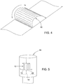
- FIG. 5 An actuating instrument 44 (for example a so-called joystick) is shown, which is equipped with appropriate control functions for controlling various work functions of a commercial vehicle, for example a tractor or another agricultural vehicle.
- the control element 10 is integrated into this actuating instrument by being arranged on a lateral surface of the actuating instrument 44. In deviation from this, an arrangement can also be provided on an upper, front, rear or lower surface of the actuating instrument 44.
- the user or driver of the commercial vehicle can therefore control both work functions and the desired change of direction in a very user-friendly manner with one hand and a single actuating instrument.
Landscapes
- Engineering & Computer Science (AREA)
- General Engineering & Computer Science (AREA)
- Mechanical Engineering (AREA)
- Chemical & Material Sciences (AREA)
- Combustion & Propulsion (AREA)
- Transportation (AREA)
- Arrangement Or Mounting Of Control Devices For Change-Speed Gearing (AREA)
- Mechanical Control Devices (AREA)
- Control Of Transmission Device (AREA)
Description
- Die Erfindung betrifft ein Verfahren und eine Anordnung zur Steuerung von Fahrzuständen eines Nutzfahrzeugs.
- Nutzfahrzeuge werden u.a. dazu verwendet, bestimmte Arbeitsfunktionen auszuführen. Dies können z.B. Lade- oder Transportarbeiten sein, zu deren Durchführung das Nutzfahrzeug über geeignete Werkzeuge verfügt. Bei einem landwirtschaftlichen Nutzfahrzeug sind diese Werkzeuge beispielsweise als eine bewegliche Ladeschaufel, Mistgabel oder ein anderes Arbeitsgerät ausgebildet. Für eine Betätigung dieser Werkzeuge sind in der Fahrerkabine des Nutzfahrzeugs üblicherweise entsprechende Betätigungselemente und -instrumente vorgesehen. Außerdem muss der Fahrer während der Ausführung solcher Arbeitsfunktionen oftmals die Fahrtrichtung zwischen "Vorwärts" und "Rückwärts" wechseln. Hierzu ist ebenfalls mindestens ein entsprechendes Betätigungselement für den Fahrer vorgesehen.
-
WO 2013/106504 A offenbart ein Steuerorgan für eine Arbeitsmaschine, mit dem zwischen Vorwärtsposition, Stillstandsposition und Rückwärtsposition umgeschaltet werden kann. - Der vorliegenden Erfindung liegt die Aufgabe zugrunde, die Steuerung des Nutzfahrzeugs während seines Betriebs zu vereinfachen. Diese Aufgabe wird gemäß den Merkmalen der unabhängigen Patentansprüche 1 und 10 gelöst.
- Das Verfahren gemäß Patentanspruch 1 ermöglicht mittels eines Steuerorgans eine wechselseitige Ansteuerung der Fahrzustände "Vorwärts" und "Rückwärts" eines Nutzfahrzeugs. Dabei bedeutet "Vorwärts" eine von einem Getriebe des Nutzfahrzeugs angetriebene Vorwärtsfahrt und "Rückwärts" eine von dem Getriebe des Nutzfahrzeugs angetriebene Rückwärtsfahrt. Aus einem aktuellen Fahrzustand ("Vorwärts" bzw. "Rückwärts") heraus ist mittels des Steuerorgans ein neuer Soll-Fahrzustand ("Rückwärts" bzw. "Vorwärts") ansteuerbar.
- Weiterhin ist ein Fahrzustand "Stillstand" vorgesehen, der einem stillstehenden Abtrieb des Fahrzeug-Getriebes ohne Trennung des Antriebsstranges durch eine Kupplung entspricht. Dieser Fahrzustand wird auch als aktiver Stillstand bezeichnet und ist insbesondere bei Traktoren mit stufenlosem Getriebe möglich. Derartige Stufenlosgetriebe ermöglichen auch ein Anfahren aus dem Stillstand ohne Anfahrkupplung. Bei Getrieben, die keinen aktiven Stillstand ermöglichen, kann die Neutralstellung des Getriebes oder das Öffnen der Fahrkupplung den Fahrzustand "Stillstand" bilden.
- Ungeachtet dessen ist der Fahrzustand "Stillstand" bei einem beabsichtigten Fahrtrichtungswechsel ("Vorwärts" nach "Rückwärts" oder "Rückwärts" nach "Vorwärts") als temporärer Betriebszustand bzw. Zwischenzustand oftmals erwünscht oder erforderlich, um das Nutzfahrzeug während seines Betriebes fahrtechnisch und sicherheitstechnisch zu unterstützen. Dabei beendet der Fahrzustand "Stillstand" die Antriebsbewegung der Antriebsachse(n) des Nutzfahrzeugs während eines aktuellen Fahrzustandes "Vorwärts" oder "Rückwärts".
- Vorzugsweise kann auch mindestens ein weiterer Fahrzustand vorgesehen sein.
- Die Steuerung des Nutzfahrzeugs, insbesondere eines Traktors oder eines anderen landwirtschaftlichen Fahrzeugs, während seines Betriebs (z.B. eine Ladetätigkeit) wird nun benutzerfreundlich vereinfacht, indem bei einem beabsichtigten Wechsel des aktuellen Fahrzustandes zu einem Soll-Fahrzustand das Steuerorgan derart betätigt wird, dass vor der Ansteuerung des Soll-Fahrzustandes automatisch zunächst der Fahrzustand "Stillstand" angesteuert wird.
- Der Begriff "Ansteuerung" eines Fahrzustandes (z.B. Soll-Fahrzustand oder "Stillstand") ist in dem Sinne zu verstehen, dass dieser Fahrzustand mittels einer Betätigung des Steuerorgans erreicht bzw. aktiviert wird.
- Dies bedeutet, dass bei einem beabsichtigten Wechsel von einem aktuellen Fahrzustand "Vorwärts" zu einem Soll-Fahrzustand "Rückwärts" oder von einem aktuellen Fahrzustand "Rückwärts" zu einem Soll-Fahrzustand "Vorwärts" zwangsläufig oder automatisch zuerst der Fahrzustand "Stillstand" angesteuert wird. Erst danach kann der eigentlich beabsichtigte Soll-Fahrzustand erreicht bzw. aktiviert werden. Hierdurch wird eine intuitive und sehr einfache Steuerung des Nutzfahrzeugs durch den Fahrzeugführer bzw. Benutzer ermöglicht, indem bei dem Richtungswechsel von "Vorwärts" nach "Rückwärts" und umgekehrt für den temporären Fahrzustand "Stillstand" herkömmlich erforderliche zusätzliche und umständliche Steuervorgänge mit anderen Steuerwegen und/oder zusätzlichen Bedienelementen vermieden werden. Vorteilhaft kann deshalb die Steuerfunktion für den Fahrzustand "Stillstand" und auch die hierfür erforderliche Steuerbewegung in ein Steuerorgan und dessen Steuerbewegungen integriert werden, welches auch zur Steuerung des eigentlichen Fahrtrichtungswechsels vorgesehen ist. Folglich kann der Benutzer auf einfache Weise einen beabsichtigten Fahrtrichtungswechsel steuern und den Fahrzustand "Stillstand" ansteuern, da das Ansteuern des Fahrzustandes "Stillstand" in den Steuervorgang des Fahrtrichtungswechsels integriert ist.
- Da der Fahrzustand "Stillstand" während einer beabsichtigten Ansteuerung eines Soll-Fahrzustandes automatisch angesteuert wird, ist ohne zusätzlichen Steuerungsaufwand seitens des Benutzers bzw. Fahrzeugführers gewährleistet, dass vor einem Fahrtrichtungswechsel erst der Fahrzustand "Stillstand" aktiviert wird.
- Dieses Ansteuerungs-Prinzip trägt dazu bei, dass die Anzahl unterschiedlicher Bedienungsfunktionen und/oder Bedienelemente zur Steuerung des Nutzfahrzeugs reduziert werden kann. Somit kann auch eine entsprechende Anordnung mit dem Steuerorgan und ggf. weiteren Bedienelementen entsprechend raumsparender und weniger komplex bereitgestellt werden.
- Vorzugsweise wird das Ansteuern des Soll-Fahrzustandes von dem Steuerorgan mittels einer Wechsel-Steuerbewegung durchgeführt, wobei der Fahrzustand "Stillstand" vor oder während einer derartigen Wechsel-Steuerbewegung automatisch erreicht wird. Hierdurch ist die Ansteuerung des temporären Fahrzustandes "Stillstand" bedienerfreundlich und intuitiv in den Ablauf der Wechsel-Steuerbewegung integriert.
- In einer vorteilhaften Ausführungsform ist das Steuerorgan während eines aktuellen Fahrzustandes lösbar arretiert, wobei diese Arretierung vor der Durchführung der Wechsel-Steuerbewegung gelöst werden muss. Hierdurch sind versehentliche Fehlbedienungen des Steuerorgans zuverlässig vermieden. Das Lösen dieser Arretierung kann vorzugsweise in einer zusätzlichen Funktion den temporären Fahrzustand "Stillstand" aktivieren. Der Fahrzustand "Stillstand" wird folglich ohne zusätzlichen Bedienungsaufwand automatisch vor einer beabsichtigten Wechsel-Steuerbewegung angesteuert.
- Zum Lösen der Arretierung kann beispielsweise ein Druckknopf an dem Steuerorgan betätigt werden. Eine Betätigung dieses Druccknopfes kann dann gleichzeitig eine Aktivierung des Fahrzustandes "Stillstand" bewirken. Diese Mehrfachfunktion des Druckknopfes unterstützt einen konstruktiv einfachen Aufbau des Steuerorgans.
- Alternativ kann ein definierter Abschnitt oder Bestandteil der Wechsel-Steuerbewegung des Steuerorgans als eine Grund-Steuerbewegung betrachtet werden, derart, dass der Fahrzustand "Stillstand" mittels einer Durchführung der Grund-Steuerbewegung angesteuert bzw. aktiviert wird. Hierdurch können unterschiedliche Bewegungsabläufe des Steuerorgans zum Ansteuern des Soll-Fahrzustands einerseits und des Fahrzustands "Stillstand" andererseits auf einfache Weise vermieden werden.
- Eine bedienungsfreundliche Ansteuerung mittels des Steuerorgans wird weiter unterstützt, indem die Wechsel-Steuerbewegung des Steuerorgans zur Aktivierung eines Soll-Fahrzustandes vorzugsweise eine wiederholte Durchführung der Grund-Steuerbewegung umfasst, insbesondere aus einer wiederholten Durchführung der Grund-Steuerbewegung besteht. Beispielsweise wird der Fahrzustand "Stillstand" durch eine erstmalige Durchführung der Grund-Steuerbewegung angesteuert, während eine sich daran anschließende nochmalige Durchführung derselben Grund-Steuerbewegung den Soll-Fahrzustand ansteuert. Hierdurch bleiben die Steuerbewegungen zur Ansteuerung der verschiedenen Fahrzustände besonders einfach und benutzerfreundlich.
- In einer weiteren bevorzugten Ausführungsform wird eine zuverlässige Betätigung des Steuerorgans unterstützt, indem während der Durchführung der Wechsel-Steuerbewegung oder Grund-Steuerbewegung mindestens eine Rastposition zum lösbaren Einrasten des Steuerorgans vorgesehen ist. Mittels der Rastposition(en) wird technisch einfach immer eine eindeutige Position des Steuerorgans während der verschiedenen Ansteuerungs-Vorgänge erzielt.
- Insbesondere entspricht das Überführen des Steuerorgans in eine Rastposition dem Ansteuern eines Fahrzustandes (insbesondere "Vorwärts", "Rückwärts" oder "Stillstand"), wodurch die Ansteuerung der verschiedenen Fahrzustände für den Benutzer noch intuitiver erfolgen kann.
- Erfindungsgemäß ist vorgesehen, dass sich das Steuerorgan während eines aktuellen Fahrzustandes in einer mittleren Ruheposition befindet. Hierdurch ist der aktuelle Status des Steuerorgans für einen Benutzer auf einfache Weise eindeutig erkennbar.
- Das Steuerorgan wird nach Ansteuerung des Fahrzustandes "Stillstand" oder eines Soll-Fahrzustandes selbsttätig (mittels eines geeigneten Mechanismus) wieder in seine Ruheposition zurückgeführt, wodurch die Handhabung des Steuerorgans für den Benutzer bzw. Fahrzeugführer weiter vereinfacht ist.
- Die einzelnen Steuerbewegungen des Steuerorgans können besonders einfach und intuitiv ausgeführt werden, indem das Steuerorgan vorzugsweise als schwenkbarer Steuerhebel ausgebildet ist.
- Alternativ kann das Steuerorgan als eine rotierbare bzw. drehbare Walze ausgebildet sein, wodurch das Steuerorgan besonders raumsparend angeordnet und komfortabel mit einem Finger seitens des Benutzers bedient werden kann.
- In der Fahrerkabine kann eine Anordnung das Steuerorgan für den Fahrtrichtungswechsel aufweisen. Diese Anordnung kann noch weitere Bedienelemente zur Steuerung oder Durchführung unterschiedlicher Funktionen des Nutzfahrzeugs (z.B. ein Traktor oder ein anderes landwirtschaftliches Fahrzeug) enthalten. Dabei kann auch ein Betätigungsinstrument zur Steuerung einer Arbeitsfunktion (z.B. Transport von Material mittels einer Ladeschaufel) des Nutzfahrzeugs als Bestandteil der Anordnung vorgesehen sein. Um die verschiedenen notwendigen Fahrtrichtungswechsel während solcher Arbeitsfunktionen für den Benutzer bzw. Fahrzeugführer komfortabler zu gestalten, ist das Steuerorgan vorzugsweise an dem vorgenannten Betätigungsinstrument angeordnet. Hierdurch kann der Benutzer mit derselben Hand an einem einzigen Betätigungsinstrument sowohl Arbeitsfunktionen als auch gewünschte Fahrtrichtungswechsel steuern.
- Das erfindungsgemäße Verfahren und eine entsprechende Anordnung werden im Folgenden anhand der beigefügten Zeichnungen näher erläutert. Dabei sind hinsichtlich ihrer Funktion übereinstimmende bzw. vergleichbare Bauteile mit denselben Bezugszeichen gekennzeichnet. Es zeigen:
-
Fig. 1 eine schematische Seitenansicht der Handhabung eines Steuerorgans in einer ersten Ausführungsform, -
Fig. 2 eine schematische Seitenansicht der Handhabung eines Steuerorgans in einer zweiten Ausführungsform, -
Fig. 3 eine schematische Seitenansicht der Handhabung eines Steuerorgans in einer dritten Ausführungsform, -
Fig. 4 eine perspektivische Darstellung einer weiteren Ausführungsform des Steuerorgans, und -
Fig. 5 eine perspektivische Darstellung eines Betätigungsinstrumentes mit einem integrierten Steuerorgan. - Anhand von
Fig. 1 bis Fig. 5 wird das Verfahren und die Anordnung mit einem Steuerorgan 10 zur Steuerung eines Fahrtrichtungswechsels eines Nutzfahrzeugs näher erläutert. Dabei sind mindestens folgende Fahrzustände für das Nutzfahrzeug möglich: - "Vorwärts" (mit dem Bezugszeichen "F") für eine von dem Getriebe des Nutzfahrzeugs angetriebene Vorwärtsfahrt,
- "Rückwärts" (mit dem Bezugszeichen "R") für eine von dem Getriebe des Nutzfahrzeugs angetriebene Rückwärtsfahrt, und
- "Stillstand" (mit dem Bezugszeichen "S") für einen stehenden Abtrieb des Getriebes ohne Trennung des Antriebsstranges des Nutzfahrzeugs. Bei Getrieben, die keinen aktiven Stillstand ermöglichen, kann die Neutralstellung des Getriebes oder das Öffnen der Fahrkupplung an die Stelle eines derartigen aktiven Stillstands treten.
-
Fig. 1 zeigt eine erste Ausführungsform für die Handhabung und Funktionsweise eines hebelartigen Steuerorgans 10, welches um ein schematisch dargestelltes Schwenklager 12 schwenkbar gelagert ist. Das Schwenklager 12 ist in hier nicht dargestellter Weise mit einem Steuermechanismus gekoppelt, der je nach Schwenkposition des Steuerorgans 10 einen gewünschten neuen Fahrzustand (Soll-Fahrzustand) aktiviert. Während eines aktuellen Fahrzustandes F, R oder S befindet sich das Steuerorgan 10 in einer mittleren Ruheposition 14. In dieser Ruheposition 14 ist das Steuerorgan 10 lösbar arretiert - beispielsweise mittels eines Arretierzapfens 13, der durch eine Federkraft vorgespannt in das Schwenklager 12 eingreift und bei Betätigung des Druccknopfes 16 aus dem Schwenklager 12 gedrückt werden kann. Fährt das Nutzfahrzeug beispielsweise aktuell rückwärts (R) und soll ein Fahrtrichtungswechsel nach F durchgeführt werden, muss der Benutzer zunächst die Arretierung des Steuerorgans 10 lösen. Hierzu wird ein Druckknopf 16 in Richtung des Schwenklagers 12 gedrückt. Diese Betätigung des Druckknopfes 16 aktiviert automatisch den Fahrzustand S. Auf diese Weise wird vor dem eigentlichen Fahrtrichtungswechsel erst der Rückwärts-Antrieb des Nutzfahrzeugs definiert und automatisch beendet. Erst nach Lösen der Arretierung, d.h. erst nach Aktivierung des Fahrzustandes S kann das Steuerorgan 10 eine Wechsel-Steuerbewegung 18 durchführen, indem es in Richtung einer Soll-Position 20 geschwenkt wird. Diese Soll-Position 20 entspricht bei aktuellem Fahrzustand R dem Soll-Fahrzustand F. Eine prinzipiell gleiche Betätigung des Steuerorgans 10 ist vorgesehen, wenn das Fahrzeug bei einem aktuellen Fahrzustand F in den Soll-Fahrzustand R wechseln soll. Das Steuerorgan 10 führt dabei eine zur Wechsel-Steuerbewegung 18 gegenläufige Wechsel-Steuerbewegung 22 in Richtung einer Soll-Position 21 durch, welche dem Soll-Fahrzustand R entspricht. Nach Ansteuerung des Soll-Fahrzustandes F oder R wird das Steuerorgan 10 mittels eines geeigneten Mechanismus selbsttätig wieder in seine Ruheposition 14 zurückgeführt. - Das Steuerorgan 10 gemäß
Fig. 2 liegt bei einem aktuellen Fahrzustand F, R oder S wiederum in der Ruheposition ein. Durch eine Federkraft und/oder lösbare Arretierung oder dergleichen kann das Steuerorgan 10 gegen unbeabsichtigte Bewegungen aus der Ruheposition heraus gesichert sein. Das Steuerorgan 10 wird wiederum geschwenkt, um eine Wechsel-Steuerbewegung 18 bzw. 22 für einen Fahrtrichtungswechsel durchzuführen. Allerdings setzt sich hier die Wechsel-Steuerbewegung 18 bzw. 22 aus zwei nacheinander durchgeführten Grund-Steuerbewegungen 24 bzw. 26 zusammen. Die Grund-Steuerbewegung 24 bzw. 26 wird also einmal wiederholt durchgeführt, um den Soll-Fahrzustand anzusteuern. Nach Durchführung der Grund-Steuerbewegung 24 bzw. 26 oder der Wechsel-Steuerbewegung 18 bzw. 22 - d.h. nach Aktivierung des Fahrzustandes S oder des Soll-Fahrzustandes F bzw. R - wird das Steuerorgan 10 mittels eines geeigneten Mechanismus selbsttätig wieder in seine Ruheposition 14 zurückgeführt. Auch bei diesem Steuerungsschema muss der Benutzer zwangsläufig bzw. automatisch erst den Fahrzustand S aktivieren, bevor der gewünschte Soll-Fahrzustand F oder R angesteuert wird. - Das Steuerorgan 10 gemäß
Fig. 3 unterscheidet sich von der Variante gemäßFig. 2 insbesondere durch eine andere Ausgestaltung der Wechsel-Steuerbewegung 18 bzw. 22. Die Grund-Steuerbewegung 24 bzw. 26 zur Ansteuerung des temporären Fahrzustandes S bildet hier einen ersten Abschnitt der gesamten Wechsel-Steuerbewegung 18 bzw. 22. Nachdem die gesamte Wechsel-Steuerbewegung 18 bzw. 22 durchgeführt wird, ist der gewünschte Soll-Fahrzustand F oder R aktiviert. Eine bedienungsfreundliche Handhabung des Steuerorgans 10 wird unterstützt, indem ausgehend von der Ruheposition 14 die anzusteuernden Zustände S, F und R jeweils einer spezifischen Rastposition 28, 30, 32 oder 34 entsprechen. In diesen Rastpositionen 28, 30, 32, 34 ist das Steuerorgan 10 lösbar eingerastet, so dass dem Benutzer der angesteuerte Fahrzustand eindeutig signalisiert wird. Dieses lösbare Einrasten wird beispielsweise mittels eines Rastelementes 36 erzielt, welches durch eine Federkraft vorgespannt gegen eine Steuerbahn 38 des Schwenklagers 12 drückt bzw. in einzelne Ausnehmungen 40, 42 dieser Steuerbahn 38 einrastet. - Bei der Variante gemäß
Fig. 3 wird das Steuerorgan 10 zumindest nach Durchführung der Wechsel-Steuerbewegung 18 bzw. 22 - d.h. nach Aktivierung des Soll-Fahrzustandes F bzw. R - mittels eines geeigneten Mechanismus selbsttätig wieder in seine Ruheposition 14 zurückgeführt. - Wie anhand von
Fig. 1 bis Fig. 3 dargestellt, kann das Steuerorgan 10 als schwenkbarer Steuerhebel ausgebildet sein. Alternativ kann das Steuerorgan 10 gemäßFig. 4 als drehbare bzw. rotationsfähige Steuerwalze ausgebildet sein, welche zur Bedienung mittels eines Fingers bzw. Daumens des Benutzers geeignet ist. Prinzipiell können bei dieser Steuerwalze dieselben Ansteuer-Schemata bzw. Steuerbewegungen realisiert werden, wie anhand vonFig. 1 bis Fig. 3 geschildert. - In
Fig. 5 ist ein Betätigungsinstrument 44 (z.B. ein sogenannter Joystick) dargestellt, welches mit entsprechenden Steuerfunktionen ausgestattet zur Steuerung verschiedener Arbeitsfunktionen eines Nutzfahrzeugs, z.B. eines Traktors oder eines anderen landwirtschaftlichen Fahrzeugs, verwendet wird. In dieses Betätigungsinstrument ist das Steuerorgan 10 integriert, indem es an einer seitlichen Oberfläche des Betätigungsinstrumentes 44 angeordnet ist. Abweichend davon kann auch eine Anordnung an einer oberen, vorderen, hinteren oder unteren Oberfläche des Betätigungsinstrumentes 44 vorgesehen sein. Der Benutzer bzw. Fahrer des Nutzfahrzeugs kann deshalb sehr bedienungsfreundlich mit einer Hand und einem einzigen Betätigungsinstrument sowohl Arbeitsfunktionen als auch erwünschte Fahrtrichtungswechsel steuern.
Claims (13)
- Verfahren zur wechselweisen Ansteuerung folgender Fahrzustände eines Nutzfahrzeugs mittels eines Steuerorgans (10) :- "Vorwärts" (F) für eine von einem Getriebe des Nutzfahrzeugs angetriebene Vorwärtsfahrt, und- "Rückwärts" (R) für eine von dem Getriebe des Nutzfahrzeugs angetriebene Rückwärtsfahrt,
wobei aus einem aktuellen Fahrzustand "Vorwärts" oder "Rückwärts" heraus ein Soll-Fahrzustand "Rückwärts" (R) oder "Vorwärts" (F) ansteuerbar ist,
wobei ein weiterer Fahrzustand "Stillstand" (S) für einen stillstehenden Abtrieb des Getriebes ohne Trennung des Antriebsstranges des Nutzfahrzeugs vorgesehen ist, und wobei vor der Ansteuerung des Soll-Fahrzustandes "Rückwärts" (R) oder "Vorwärts" (F) der Fahrzustand "Stillstand" (S) angesteuert wird, dadurch gekennzeichnet, dass sich das Steuerorgan (10) während eines aktuellen Fahrzustandes (F, R, S) in einer mittleren Ruheposition (14) befindet, in die das Steuerorgan (10) nach Ansteuerung des Fahrzustandes "Stillstand" (S) und/oder des Soll-Fahrzustandes "Vorwärts" (F) oder "Rückwärts" selbsttätig wieder zurückgeführt wird. - Verfahren nach Anspruch 1, dadurch gekennzeichnet, dass zum Ansteuern des Soll-Fahrzustandes (F, R) von dem Steuerorgan (10) eine Wechsel-Steuerbewegung (18, 22) durchgeführt wird, wobei der Fahrzustand "Stillstand" (S) vor oder während der Wechsel-Steuerbewegung (18, 22) angesteuert wird.
- Verfahren nach Anspruch 2, dadurch gekennzeichnet, dass das Steuerorgan (10) während des aktuellen Fahrzustandes lösbar arretiert ist, wobei diese Arretierung (13) vor Durchführung der Wechsel-Steuerbewegung (18, 22) gelöst wird.
- Verfahren nach Anspruch 3, dadurch gekennzeichnet, dass der Fahrzustand "Stillstand" (S) durch Lösen der Arretierung (13) angesteuert wird.
- Verfahren nach Anspruch 2 oder 3, dadurch gekennzeichnet, dass der Fahrzustand "Stillstand" (S) mittels einer Grund-Steuerbewegung (24, 26) als Bestandteil der Wechsel-Steuerbewegung (18, 22) des Steuerorgans (10) angesteuert wird.
- Verfahren nach Anspruch 5, dadurch gekennzeichnet, dass die Wechsel-Steuerbewegung (18, 22) des Steuerorgans (10) zur Ansteuerung des Soll-Fahrzustandes (F, R) eine wiederholte Durchführung der Grund-Steuerbewegung (24, 26) des Steuerorgans (10) umfasst.
- Verfahren nach einem der Ansprüche 2 bis 6, dadurch gekennzeichnet, dass während der Wechsel-Steuerbewegung (18, 22) oder Grund-Steuerbewegung (24, 26) mindestens eine Rastposition (28, 30, 32, 34) zum lösbaren Einrasten des Steuerorgans (10) vorgesehen ist.
- Verfahren nach Anspruch 7, dadurch gekennzeichnet, dass der Fahrzustand "Stillstand" (S) mittels Überführen des Steuerorgans (10) in eine Rastposition (28, 32) angesteuert wird.
- Verfahren nach Anspruch 7 oder 8, dadurch gekennzeichnet, dass der Soll-Fahrzustand (F, R) mittels Überführen des Steuerorgans (10) in eine Rastposition (30, 34) angesteuert wird.
- Anordnung mit einem Steuerorgan (10) zur wechselweisen Ansteuerung folgender Fahrzustände eines Nutzfahrzeugs:- "Vorwärts" (F) für eine von einem Getriebe des Nutzfahrzeugs angetriebene Vorwärtsfahrt, und- "Rückwärts" (R) für eine von dem Getriebe des Nutzfahrzeugs angetriebene Rückwärtsfahrt,
wobei aus einem aktuellen Fahrzustand "Vorwärts" oder "Rückwärts" heraus ein Soll-Fahrzustand "Rückwärts" (R) oder "Vorwärts" (F) ansteuerbar ist,
wobei ein weiterer Fahrzustand "Stillstand" (S) für einen stillstehenden Abtrieb des Getriebes ohne Trennung des Antriebsstranges des Nutzfahrzeugs vorgesehen ist, wobei das Steuerorgan (10) derart ausgebildet ist, dass es vor der Ansteuerung des Soll-Fahrzustandes "Rückwärts" (R) oder "Vorwärts" (F) den Fahrzustand "Stillstand" (S) ansteuert, dadurch gekennzeichnet, dass sich das Steuerorgan (10) während eines aktuellen Fahrzustandes (F, R, S) in einer mittleren Ruheposition (14) befindet, in die das Steuerorgan (10) nach Ansteuerung des Fahrzustandes "Stillstand" (S) und des Soll-Fahrzustandes "Vorwärts" (F) oder "Rückwärts" wieder selbsttätig zurückgeführt wird. - Anordnung nach Anspruch 10, dadurch gekennzeichnet, dass das Steuerorgan (10) als schwenkbarer Steuerhebel ausgebildet ist.
- Anordnung nach Anspruch 10, dadurch gekennzeichnet, dass das Steuerorgan (10) als drehbare Steuerwalze ausgebildet ist.
- Anordnung nach einem der Ansprüche 10 bis 12, dadurch gekennzeichnet, dass das Steuerorgan (10) an einem Betätigungsinstrument (44) angeordnet ist, welches zur Steuerung mindestens einer Arbeitsfunktion mittels des Nutzfahrzeugs ausgebildet ist.
Applications Claiming Priority (1)
| Application Number | Priority Date | Filing Date | Title |
|---|---|---|---|
| DE102016203763.3A DE102016203763A1 (de) | 2016-03-08 | 2016-03-08 | Verfahren und Anordnung zur Steuerung von Fahrzuständen eines Nutzfahrzeugs |
Publications (2)
| Publication Number | Publication Date |
|---|---|
| EP3217042A1 EP3217042A1 (de) | 2017-09-13 |
| EP3217042B1 true EP3217042B1 (de) | 2020-05-06 |
Family
ID=58192192
Family Applications (1)
| Application Number | Title | Priority Date | Filing Date |
|---|---|---|---|
| EP17158436.0A Active EP3217042B1 (de) | 2016-03-08 | 2017-02-28 | Verfahren und anordnung zur steuerung von fahrzuständen eines nutzfahrzeugs |
Country Status (3)
| Country | Link |
|---|---|
| US (1) | US10975962B2 (de) |
| EP (1) | EP3217042B1 (de) |
| DE (1) | DE102016203763A1 (de) |
Families Citing this family (2)
| Publication number | Priority date | Publication date | Assignee | Title |
|---|---|---|---|---|
| KR101954191B1 (ko) * | 2017-09-29 | 2019-03-05 | 경창산업주식회사 | 이중 힌지를 이용한 변속제어장치 |
| DE102019122975A1 (de) * | 2019-08-27 | 2021-03-04 | Bayerische Motoren Werke Aktiengesellschaft | Getriebesystem mit einem automatischen schaltgetriebe |
Family Cites Families (19)
| Publication number | Priority date | Publication date | Assignee | Title |
|---|---|---|---|---|
| US2916928A (en) * | 1940-10-09 | 1959-12-15 | Chrysler Corp | Power transmission |
| DE19502482A1 (de) * | 1995-01-27 | 1996-08-01 | Zahnradfabrik Friedrichshafen | Fahrschalter für ein Fahrzeug |
| DE19637533B4 (de) * | 1996-09-14 | 2007-03-22 | Zf Friedrichshafen Ag | Elektrischer Fahrschalter |
| JP4846913B2 (ja) * | 2001-03-06 | 2011-12-28 | 株式会社東海理化電機製作所 | シフト装置 |
| DE10140975A1 (de) * | 2001-08-27 | 2003-03-20 | Claas Selbstfahr Erntemasch | Vorrichtung zum Steuern eines landwirtschaftlichen Fahrzeugs |
| DE10217614B4 (de) * | 2002-04-19 | 2017-04-13 | Bayerische Motoren Werke Aktiengesellschaft | Bedienelement zum Anwählen von Betriebszuständen eines Getriebes |
| JP2006219034A (ja) * | 2005-02-10 | 2006-08-24 | Denso Corp | 運転許可装置 |
| US7603218B2 (en) * | 2005-07-16 | 2009-10-13 | Cnh America Llc | Apparatus and method to provide failsafe deceleration for an agricultural windrower |
| JP2008039112A (ja) * | 2006-08-08 | 2008-02-21 | Toyota Motor Corp | 自動変速機のシフト切換装置 |
| JP4735630B2 (ja) * | 2007-09-28 | 2011-07-27 | トヨタ自動車株式会社 | 自動変速制御装置 |
| US7984784B2 (en) * | 2008-05-23 | 2011-07-26 | Deere & Company | Directional transmission control with ECU authorization |
| DE112009005464B4 (de) * | 2009-12-22 | 2017-03-02 | Toyota Jidosha Kabushiki Kaisha | Schaltungssteuerungsvorrichtung für ein fahrzeug |
| RU2531787C1 (ru) * | 2010-08-31 | 2014-10-27 | Ниссан Мотор Ко., Лтд. | Устройство управления автоматической трансмиссией |
| DE102011087330A1 (de) * | 2011-11-29 | 2013-05-29 | Bayerische Motoren Werke Aktiengesellschaft | Betätigungsvorrichtung für ein Getriebe eines Kraftfahrzeugs |
| US8954245B2 (en) * | 2012-01-13 | 2015-02-10 | Caterpillar Inc. | Method of controlling gear ratio rate of change in continuously variable transmission |
| JP6094192B2 (ja) * | 2012-12-11 | 2017-03-15 | 三菱自動車工業株式会社 | シフト装置 |
| US20150020634A1 (en) * | 2013-07-18 | 2015-01-22 | Jay T. TenBrink | Lever style electronic shifter with concealed lever position |
| US20150114158A1 (en) * | 2013-10-24 | 2015-04-30 | Jay T. TenBrink | Transmission electronic shifter with dual mechanical detents |
| JP6601773B2 (ja) * | 2016-02-25 | 2019-11-06 | パナソニックIpマネジメント株式会社 | セレクタ |
-
2016
- 2016-03-08 DE DE102016203763.3A patent/DE102016203763A1/de not_active Withdrawn
-
2017
- 2017-02-28 EP EP17158436.0A patent/EP3217042B1/de active Active
- 2017-03-03 US US15/448,847 patent/US10975962B2/en active Active
Non-Patent Citations (1)
| Title |
|---|
| None * |
Also Published As
| Publication number | Publication date |
|---|---|
| EP3217042A1 (de) | 2017-09-13 |
| US20170261100A1 (en) | 2017-09-14 |
| DE102016203763A1 (de) | 2017-09-14 |
| US10975962B2 (en) | 2021-04-13 |
Similar Documents
| Publication | Publication Date | Title |
|---|---|---|
| DE2004249C3 (de) | Getriebeschalthebel-Baugruppe für ein mehrgängiges Fahrzeuggetriebe | |
| EP2583003A2 (de) | Vorrichtung zur bedienung von funktionen eines kraftfahrzeugs | |
| DE3221634C2 (de) | Vorrichtung zum Betätigen eines Getriebes eines vierradgetriebenen Kraftfahrzeugs | |
| DE19642956A1 (de) | Bedienungseinrichtung für lenkbare Nutzfahrzeuge, insbesondere Radfahrzeuge | |
| EP1836421B1 (de) | Vorrichtung zur betätigung von schaltgabeln | |
| EP3217042B1 (de) | Verfahren und anordnung zur steuerung von fahrzuständen eines nutzfahrzeugs | |
| DE102017123163B4 (de) | Bedienvorrichtung zum Steuern eines Werkzeuges oder einer Arbeitsmaschine | |
| DE102018121207B4 (de) | Fahrzeugschaltvorrichtung | |
| EP0941886A2 (de) | Fahrzeuggetriebebetätigungseinrichtung am Lenkrad | |
| DE202014007664U1 (de) | Umkonfigurierbares Lenkrad | |
| DE1932332C3 (de) | Als Gruppengetriebe ausgebildetes Zahnräderwechselgetriebe für Fahrzeuge, insbesondere für landwirtschaftlich nutzbare Fahrzeuge | |
| DE1680046B2 (de) | Schaltvorrichtung für Wechselgetriebe von Kraftfahrzeugen | |
| DE102014208350B4 (de) | Kraftfahrzeug mit einer Vorrichtung zur wenigstens teilweisen Steuerung der Längs- und/oder Querdynamik des Kraftfahrzeugs mit der Hand | |
| DE102011003586A1 (de) | Multifunktionsbedienelement | |
| DE2940508A1 (de) | Arbeitsfahrzeug, das von einer bedienungsperson zu begleiten ist | |
| DE102014208349B4 (de) | Kraftfahrzeug mit einer Vorrichtung zur wenigstens teilweisen Steuerung der Längs- und/oder Querdynamik des Kraftfahrzeugs mit der Hand | |
| DE102018220016A1 (de) | Shift-by-wire-vorrichtung | |
| DE60213369T2 (de) | Steuerungsvorrichtung für ein Kraftfahrzeug | |
| DE102021103595A1 (de) | Fahrzeuglenksystem und verfahren zum umschalten des kopplungsmechanismus | |
| DE102015223341A1 (de) | Lenkrad für ein Fahrzeug | |
| DE2851736C2 (de) | Sicherheitseinrichtung als Drehsicherung für eine aus Fahrersitz, Bedienungsstand und Lenkbetätigungseinrichtung bestehende drehbare Sitzbedienungseinheit eines Nutzfahrzeuges | |
| DE69108399T2 (de) | Gangschaltvorrichtung. | |
| DE2042827B2 (de) | Fotografische kamera, insbesondere laufbildkamera | |
| DE355698C (de) | Schaltvorrichtung fuer Zahnraederwechselgetriebe von Kraftfahrzeugen | |
| WO2025163174A1 (de) | Kinderwagen |
Legal Events
| Date | Code | Title | Description |
|---|---|---|---|
| PUAI | Public reference made under article 153(3) epc to a published international application that has entered the european phase |
Free format text: ORIGINAL CODE: 0009012 |
|
| STAA | Information on the status of an ep patent application or granted ep patent |
Free format text: STATUS: THE APPLICATION HAS BEEN PUBLISHED |
|
| AK | Designated contracting states |
Kind code of ref document: A1 Designated state(s): AL AT BE BG CH CY CZ DE DK EE ES FI FR GB GR HR HU IE IS IT LI LT LU LV MC MK MT NL NO PL PT RO RS SE SI SK SM TR |
|
| AX | Request for extension of the european patent |
Extension state: BA ME |
|
| STAA | Information on the status of an ep patent application or granted ep patent |
Free format text: STATUS: REQUEST FOR EXAMINATION WAS MADE |
|
| 17P | Request for examination filed |
Effective date: 20180313 |
|
| RBV | Designated contracting states (corrected) |
Designated state(s): AL AT BE BG CH CY CZ DE DK EE ES FI FR GB GR HR HU IE IS IT LI LT LU LV MC MK MT NL NO PL PT RO RS SE SI SK SM TR |
|
| RIC1 | Information provided on ipc code assigned before grant |
Ipc: F16H 59/08 20060101AFI20191024BHEP |
|
| GRAP | Despatch of communication of intention to grant a patent |
Free format text: ORIGINAL CODE: EPIDOSNIGR1 |
|
| STAA | Information on the status of an ep patent application or granted ep patent |
Free format text: STATUS: GRANT OF PATENT IS INTENDED |
|
| INTG | Intention to grant announced |
Effective date: 20191202 |
|
| GRAS | Grant fee paid |
Free format text: ORIGINAL CODE: EPIDOSNIGR3 |
|
| GRAA | (expected) grant |
Free format text: ORIGINAL CODE: 0009210 |
|
| STAA | Information on the status of an ep patent application or granted ep patent |
Free format text: STATUS: THE PATENT HAS BEEN GRANTED |
|
| AK | Designated contracting states |
Kind code of ref document: B1 Designated state(s): AL AT BE BG CH CY CZ DE DK EE ES FI FR GB GR HR HU IE IS IT LI LT LU LV MC MK MT NL NO PL PT RO RS SE SI SK SM TR |
|
| REG | Reference to a national code |
Ref country code: GB Ref legal event code: FG4D Free format text: NOT ENGLISH |
|
| REG | Reference to a national code |
Ref country code: AT Ref legal event code: REF Ref document number: 1267263 Country of ref document: AT Kind code of ref document: T Effective date: 20200515 Ref country code: CH Ref legal event code: EP |
|
| REG | Reference to a national code |
Ref country code: DE Ref legal event code: R096 Ref document number: 502017005089 Country of ref document: DE |
|
| REG | Reference to a national code |
Ref country code: IE Ref legal event code: FG4D Free format text: LANGUAGE OF EP DOCUMENT: GERMAN |
|
| REG | Reference to a national code |
Ref country code: FI Ref legal event code: FGE |
|
| REG | Reference to a national code |
Ref country code: LT Ref legal event code: MG4D |
|
| REG | Reference to a national code |
Ref country code: NL Ref legal event code: MP Effective date: 20200506 |
|
| PG25 | Lapsed in a contracting state [announced via postgrant information from national office to epo] |
Ref country code: GR Free format text: LAPSE BECAUSE OF FAILURE TO SUBMIT A TRANSLATION OF THE DESCRIPTION OR TO PAY THE FEE WITHIN THE PRESCRIBED TIME-LIMIT Effective date: 20200807 Ref country code: LT Free format text: LAPSE BECAUSE OF FAILURE TO SUBMIT A TRANSLATION OF THE DESCRIPTION OR TO PAY THE FEE WITHIN THE PRESCRIBED TIME-LIMIT Effective date: 20200506 Ref country code: IS Free format text: LAPSE BECAUSE OF FAILURE TO SUBMIT A TRANSLATION OF THE DESCRIPTION OR TO PAY THE FEE WITHIN THE PRESCRIBED TIME-LIMIT Effective date: 20200906 Ref country code: SE Free format text: LAPSE BECAUSE OF FAILURE TO SUBMIT A TRANSLATION OF THE DESCRIPTION OR TO PAY THE FEE WITHIN THE PRESCRIBED TIME-LIMIT Effective date: 20200506 Ref country code: NO Free format text: LAPSE BECAUSE OF FAILURE TO SUBMIT A TRANSLATION OF THE DESCRIPTION OR TO PAY THE FEE WITHIN THE PRESCRIBED TIME-LIMIT Effective date: 20200806 Ref country code: PT Free format text: LAPSE BECAUSE OF FAILURE TO SUBMIT A TRANSLATION OF THE DESCRIPTION OR TO PAY THE FEE WITHIN THE PRESCRIBED TIME-LIMIT Effective date: 20200907 |
|
| PG25 | Lapsed in a contracting state [announced via postgrant information from national office to epo] |
Ref country code: RS Free format text: LAPSE BECAUSE OF FAILURE TO SUBMIT A TRANSLATION OF THE DESCRIPTION OR TO PAY THE FEE WITHIN THE PRESCRIBED TIME-LIMIT Effective date: 20200506 Ref country code: HR Free format text: LAPSE BECAUSE OF FAILURE TO SUBMIT A TRANSLATION OF THE DESCRIPTION OR TO PAY THE FEE WITHIN THE PRESCRIBED TIME-LIMIT Effective date: 20200506 Ref country code: LV Free format text: LAPSE BECAUSE OF FAILURE TO SUBMIT A TRANSLATION OF THE DESCRIPTION OR TO PAY THE FEE WITHIN THE PRESCRIBED TIME-LIMIT Effective date: 20200506 Ref country code: BG Free format text: LAPSE BECAUSE OF FAILURE TO SUBMIT A TRANSLATION OF THE DESCRIPTION OR TO PAY THE FEE WITHIN THE PRESCRIBED TIME-LIMIT Effective date: 20200806 |
|
| PG25 | Lapsed in a contracting state [announced via postgrant information from national office to epo] |
Ref country code: AL Free format text: LAPSE BECAUSE OF FAILURE TO SUBMIT A TRANSLATION OF THE DESCRIPTION OR TO PAY THE FEE WITHIN THE PRESCRIBED TIME-LIMIT Effective date: 20200506 Ref country code: NL Free format text: LAPSE BECAUSE OF FAILURE TO SUBMIT A TRANSLATION OF THE DESCRIPTION OR TO PAY THE FEE WITHIN THE PRESCRIBED TIME-LIMIT Effective date: 20200506 |
|
| PG25 | Lapsed in a contracting state [announced via postgrant information from national office to epo] |
Ref country code: CZ Free format text: LAPSE BECAUSE OF FAILURE TO SUBMIT A TRANSLATION OF THE DESCRIPTION OR TO PAY THE FEE WITHIN THE PRESCRIBED TIME-LIMIT Effective date: 20200506 Ref country code: ES Free format text: LAPSE BECAUSE OF FAILURE TO SUBMIT A TRANSLATION OF THE DESCRIPTION OR TO PAY THE FEE WITHIN THE PRESCRIBED TIME-LIMIT Effective date: 20200506 Ref country code: RO Free format text: LAPSE BECAUSE OF FAILURE TO SUBMIT A TRANSLATION OF THE DESCRIPTION OR TO PAY THE FEE WITHIN THE PRESCRIBED TIME-LIMIT Effective date: 20200506 Ref country code: DK Free format text: LAPSE BECAUSE OF FAILURE TO SUBMIT A TRANSLATION OF THE DESCRIPTION OR TO PAY THE FEE WITHIN THE PRESCRIBED TIME-LIMIT Effective date: 20200506 Ref country code: SM Free format text: LAPSE BECAUSE OF FAILURE TO SUBMIT A TRANSLATION OF THE DESCRIPTION OR TO PAY THE FEE WITHIN THE PRESCRIBED TIME-LIMIT Effective date: 20200506 Ref country code: EE Free format text: LAPSE BECAUSE OF FAILURE TO SUBMIT A TRANSLATION OF THE DESCRIPTION OR TO PAY THE FEE WITHIN THE PRESCRIBED TIME-LIMIT Effective date: 20200506 |
|
| REG | Reference to a national code |
Ref country code: DE Ref legal event code: R097 Ref document number: 502017005089 Country of ref document: DE |
|
| PG25 | Lapsed in a contracting state [announced via postgrant information from national office to epo] |
Ref country code: SK Free format text: LAPSE BECAUSE OF FAILURE TO SUBMIT A TRANSLATION OF THE DESCRIPTION OR TO PAY THE FEE WITHIN THE PRESCRIBED TIME-LIMIT Effective date: 20200506 Ref country code: PL Free format text: LAPSE BECAUSE OF FAILURE TO SUBMIT A TRANSLATION OF THE DESCRIPTION OR TO PAY THE FEE WITHIN THE PRESCRIBED TIME-LIMIT Effective date: 20200506 |
|
| PLBE | No opposition filed within time limit |
Free format text: ORIGINAL CODE: 0009261 |
|
| STAA | Information on the status of an ep patent application or granted ep patent |
Free format text: STATUS: NO OPPOSITION FILED WITHIN TIME LIMIT |
|
| 26N | No opposition filed |
Effective date: 20210209 |
|
| PG25 | Lapsed in a contracting state [announced via postgrant information from national office to epo] |
Ref country code: SI Free format text: LAPSE BECAUSE OF FAILURE TO SUBMIT A TRANSLATION OF THE DESCRIPTION OR TO PAY THE FEE WITHIN THE PRESCRIBED TIME-LIMIT Effective date: 20200506 |
|
| PG25 | Lapsed in a contracting state [announced via postgrant information from national office to epo] |
Ref country code: MC Free format text: LAPSE BECAUSE OF FAILURE TO SUBMIT A TRANSLATION OF THE DESCRIPTION OR TO PAY THE FEE WITHIN THE PRESCRIBED TIME-LIMIT Effective date: 20200506 |
|
| REG | Reference to a national code |
Ref country code: BE Ref legal event code: MM Effective date: 20210228 |
|
| PG25 | Lapsed in a contracting state [announced via postgrant information from national office to epo] |
Ref country code: LI Free format text: LAPSE BECAUSE OF NON-PAYMENT OF DUE FEES Effective date: 20210228 Ref country code: LU Free format text: LAPSE BECAUSE OF NON-PAYMENT OF DUE FEES Effective date: 20210228 Ref country code: CH Free format text: LAPSE BECAUSE OF NON-PAYMENT OF DUE FEES Effective date: 20210228 |
|
| PG25 | Lapsed in a contracting state [announced via postgrant information from national office to epo] |
Ref country code: IE Free format text: LAPSE BECAUSE OF NON-PAYMENT OF DUE FEES Effective date: 20210228 |
|
| PG25 | Lapsed in a contracting state [announced via postgrant information from national office to epo] |
Ref country code: BE Free format text: LAPSE BECAUSE OF NON-PAYMENT OF DUE FEES Effective date: 20210228 |
|
| PG25 | Lapsed in a contracting state [announced via postgrant information from national office to epo] |
Ref country code: HU Free format text: LAPSE BECAUSE OF FAILURE TO SUBMIT A TRANSLATION OF THE DESCRIPTION OR TO PAY THE FEE WITHIN THE PRESCRIBED TIME-LIMIT; INVALID AB INITIO Effective date: 20170228 |
|
| PG25 | Lapsed in a contracting state [announced via postgrant information from national office to epo] |
Ref country code: CY Free format text: LAPSE BECAUSE OF FAILURE TO SUBMIT A TRANSLATION OF THE DESCRIPTION OR TO PAY THE FEE WITHIN THE PRESCRIBED TIME-LIMIT Effective date: 20200506 |
|
| PGFP | Annual fee paid to national office [announced via postgrant information from national office to epo] |
Ref country code: AT Payment date: 20240201 Year of fee payment: 8 |
|
| PG25 | Lapsed in a contracting state [announced via postgrant information from national office to epo] |
Ref country code: MK Free format text: LAPSE BECAUSE OF FAILURE TO SUBMIT A TRANSLATION OF THE DESCRIPTION OR TO PAY THE FEE WITHIN THE PRESCRIBED TIME-LIMIT Effective date: 20200506 |
|
| PG25 | Lapsed in a contracting state [announced via postgrant information from national office to epo] |
Ref country code: MT Free format text: LAPSE BECAUSE OF FAILURE TO SUBMIT A TRANSLATION OF THE DESCRIPTION OR TO PAY THE FEE WITHIN THE PRESCRIBED TIME-LIMIT Effective date: 20200506 |
|
| REG | Reference to a national code |
Ref country code: AT Ref legal event code: MM01 Ref document number: 1267263 Country of ref document: AT Kind code of ref document: T Effective date: 20250228 |
|
| PG25 | Lapsed in a contracting state [announced via postgrant information from national office to epo] |
Ref country code: AT Free format text: LAPSE BECAUSE OF NON-PAYMENT OF DUE FEES Effective date: 20250228 |
|
| PG25 | Lapsed in a contracting state [announced via postgrant information from national office to epo] |
Ref country code: TR Free format text: LAPSE BECAUSE OF FAILURE TO SUBMIT A TRANSLATION OF THE DESCRIPTION OR TO PAY THE FEE WITHIN THE PRESCRIBED TIME-LIMIT Effective date: 20200506 |
|
| PGFP | Annual fee paid to national office [announced via postgrant information from national office to epo] |
Ref country code: GB Payment date: 20260227 Year of fee payment: 10 |
|
| PGFP | Annual fee paid to national office [announced via postgrant information from national office to epo] |
Ref country code: DE Payment date: 20260121 Year of fee payment: 10 |
|
| PGFP | Annual fee paid to national office [announced via postgrant information from national office to epo] |
Ref country code: FI Payment date: 20260225 Year of fee payment: 10 Ref country code: IT Payment date: 20260219 Year of fee payment: 10 |
|
| PGFP | Annual fee paid to national office [announced via postgrant information from national office to epo] |
Ref country code: FR Payment date: 20260225 Year of fee payment: 10 |