EP3217150A1 - Vorrichtung zur drehwinkelerfassung und verfahren zur drehwinkelerfassung - Google Patents
Vorrichtung zur drehwinkelerfassung und verfahren zur drehwinkelerfassung Download PDFInfo
- Publication number
- EP3217150A1 EP3217150A1 EP14905520.4A EP14905520A EP3217150A1 EP 3217150 A1 EP3217150 A1 EP 3217150A1 EP 14905520 A EP14905520 A EP 14905520A EP 3217150 A1 EP3217150 A1 EP 3217150A1
- Authority
- EP
- European Patent Office
- Prior art keywords
- circuit
- excitation
- amplitude
- resolver
- frequency
- Prior art date
- Legal status (The legal status is an assumption and is not a legal conclusion. Google has not performed a legal analysis and makes no representation as to the accuracy of the status listed.)
- Granted
Links
Images

Classifications
-
- G—PHYSICS
- G01—MEASURING; TESTING
- G01D—MEASURING NOT SPECIALLY ADAPTED FOR A SPECIFIC VARIABLE; ARRANGEMENTS FOR MEASURING TWO OR MORE VARIABLES NOT COVERED IN A SINGLE OTHER SUBCLASS; TARIFF METERING APPARATUS; MEASURING OR TESTING NOT OTHERWISE PROVIDED FOR
- G01D5/00—Mechanical means for transferring the output of a sensing member; Means for converting the output of a sensing member to another variable where the form or nature of the sensing member does not constrain the means for converting; Transducers not specially adapted for a specific variable
- G01D5/12—Mechanical means for transferring the output of a sensing member; Means for converting the output of a sensing member to another variable where the form or nature of the sensing member does not constrain the means for converting; Transducers not specially adapted for a specific variable using electric or magnetic means
- G01D5/14—Mechanical means for transferring the output of a sensing member; Means for converting the output of a sensing member to another variable where the form or nature of the sensing member does not constrain the means for converting; Transducers not specially adapted for a specific variable using electric or magnetic means influencing the magnitude of a current or voltage
- G01D5/20—Mechanical means for transferring the output of a sensing member; Means for converting the output of a sensing member to another variable where the form or nature of the sensing member does not constrain the means for converting; Transducers not specially adapted for a specific variable using electric or magnetic means influencing the magnitude of a current or voltage by varying inductance, e.g. by a movable armature
-
- G—PHYSICS
- G01—MEASURING; TESTING
- G01D—MEASURING NOT SPECIALLY ADAPTED FOR A SPECIFIC VARIABLE; ARRANGEMENTS FOR MEASURING TWO OR MORE VARIABLES NOT COVERED IN A SINGLE OTHER SUBCLASS; TARIFF METERING APPARATUS; MEASURING OR TESTING NOT OTHERWISE PROVIDED FOR
- G01D5/00—Mechanical means for transferring the output of a sensing member; Means for converting the output of a sensing member to another variable where the form or nature of the sensing member does not constrain the means for converting; Transducers not specially adapted for a specific variable
- G01D5/12—Mechanical means for transferring the output of a sensing member; Means for converting the output of a sensing member to another variable where the form or nature of the sensing member does not constrain the means for converting; Transducers not specially adapted for a specific variable using electric or magnetic means
- G01D5/14—Mechanical means for transferring the output of a sensing member; Means for converting the output of a sensing member to another variable where the form or nature of the sensing member does not constrain the means for converting; Transducers not specially adapted for a specific variable using electric or magnetic means influencing the magnitude of a current or voltage
- G01D5/20—Mechanical means for transferring the output of a sensing member; Means for converting the output of a sensing member to another variable where the form or nature of the sensing member does not constrain the means for converting; Transducers not specially adapted for a specific variable using electric or magnetic means influencing the magnitude of a current or voltage by varying inductance, e.g. by a movable armature
- G01D5/204—Mechanical means for transferring the output of a sensing member; Means for converting the output of a sensing member to another variable where the form or nature of the sensing member does not constrain the means for converting; Transducers not specially adapted for a specific variable using electric or magnetic means influencing the magnitude of a current or voltage by varying inductance, e.g. by a movable armature by influencing the mutual induction between two or more coils
- G01D5/2066—Mechanical means for transferring the output of a sensing member; Means for converting the output of a sensing member to another variable where the form or nature of the sensing member does not constrain the means for converting; Transducers not specially adapted for a specific variable using electric or magnetic means influencing the magnitude of a current or voltage by varying inductance, e.g. by a movable armature by influencing the mutual induction between two or more coils by movement of a single coil with respect to a single other coil
-
- H—ELECTRICITY
- H02—GENERATION; CONVERSION OR DISTRIBUTION OF ELECTRIC POWER
- H02K—DYNAMO-ELECTRIC MACHINES
- H02K24/00—Machines adapted for the instantaneous transmission or reception of the angular displacement of rotating parts, e.g. synchro, selsyn
Definitions
- the present invention relates to a rotation angle detection device and a rotation angle detection method for detecting a rotation angle and rotation speed of a motor generator, by using a resolver.
- Resolvers which have a simpler structure than optical encoders and show little error with temperature change, are widely used as rotation angle detection devices for detecting the rotation angle and rotation speed of a motor generator.
- resolvers are susceptible to the effects of external magnetic flux generated by the motor coil, etc. of the motor generator. Therefore, in order to reduce the effects of external magnetic flux, various structural measures have been devised for the coils of a resolver (see, for example, PTL 1).
- the S/N ratio of the induction signal induced in the induction coil of the resolver is improved by raising the amplitude or frequency of the excitation signal which is applied to the excitation coil of the resolver.
- the detection accuracy of the rotation angle and rotation speed of the resolver (abbreviated as "resolver detection accuracy” below) is not required to be of the same level as during a driving operation of the motor generator. More specifically, the resolver detection accuracy during a power generating operation of the motor generator is sufficient provided that the detection accuracy enables the rotation speed to be detected.
- the resolver detection accuracy is not required to be of the same level as during a driving operation of the motor generator. Consequently, there is a problem in that it is inefficient to use the same excitation signal having a large amplitude or frequency during both, for instance, a driving operation, in which high resolver detection accuracy is required, and a power generating operation, in which it is sufficient to maintain a resolver detection accuracy that enables information about the rotation speed of the motor generator to be obtained.
- the present invention was devised in order to solve the abovementioned problem, an object thereof being to obtain a rotation angle detection device and a rotation angle detection method wherein downsizing can be achieved, and wherein a high resolver detection accuracy can be obtained during a driving operation of the motor generator, and when the motor generator is not performing a driving operation, the power consumption and amount of heat generated by the excitation circuit and resolver can be suppressed, while maintaining a resolver detection accuracy that enables information about the rotation speed of the motor generator to be obtained.
- the rotation angle detection device includes: a resolver which has an excitation coil and an induction coil, and which a magnetic field formed by an excitation signal applied to the excitation coil is frequency-modulated by rotation of a motor generator and induced in the induction coil; an excitation circuit which applies the excitation signal, which is sinusoidal, to the excitation coil of the resolver; a power supply circuit which supplies power to the excitation circuit; an amplification circuit which amplifies and outputs an amplitude of an induction signal induced in the induction coil; and an angle calculation unit which detects a rotation angle and a rotation speed of the motor generator, which is capable of a driving operation and a power generating operation, from the excitation signal output by the excitation circuit and from the induction signal output by the amplification circuit, the rotation angle detection device further including: a first switching circuit which, in an on state, switches an amplitude or a frequency of the excitation signal to an "amplitude value when on", or a "frequency when on", by which a required
- the rotation angle detection method is a rotation angle detection method used in a rotation angle detection device including: a resolver which has an excitation coil and an induction coil, and in which a magnetic field formed by an excitation signal applied to the excitation coil is frequency-modulated by rotation of a motor generator and induced in the induction coil; an excitation circuit which applies the excitation signal, which is sinusoidal, to the excitation coil of the resolver; a power supply circuit which supplies power to the excitation circuit; an amplification circuit which amplifies and outputs an amplitude of an induction signal which is induced in the induction coil; and an angle calculation unit which detects a rotation angle and a rotation speed of the motor generator, which is capable of a driving operation and a power generating operation, from the excitation signal output by the excitation circuit and from the induction signal output by the amplification circuit, the method including: an on switching step in which an amplitude or a frequency of the excitation signal is switched to an amplitude value when on or a frequency when
- the resolver detection accuracy is improved by raising the amplitude or frequency of the excitation signal. Furthermore, when a driving operation of the motor generator is not being performed, the amount of heat generated by the resolver and the excitation circuit is suppressed by reducing the amplitude or frequency of the excitation signal.
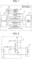
- Fig. 1 is a block drawing showing the configuration of a rotation angle detection device 1 according to a first embodiment of the present invention.
- the rotation angle detection device 1 of the first embodiment comprises a resolver 10, an excitation circuit 11, a power supply circuit 12, an amplification circuit 13, an angle calculation unit 14, a first switching circuit 21, a second switching circuit 22, and a control unit 23.
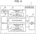
- Fig. 2 is a circuit diagram illustrating one example of the excitation circuit 11 in the rotation angle detection device 1 according to the first embodiment of the present invention. Below, the constituent elements and functions of the rotation angle detection device 1 according to the first embodiment will be described with reference to Fig. 1 and Fig. 2 .
- the resolver 10 has an excitation coil and an induction coil.
- a magnetic field produced by an excitation signal applied to the excitation coil of the resolver 10 is frequency-modulated by the rotation of a rotary shaft of the motor generator, and induced as an induction signal in the induction coil of the resolver 10. Consequently, by comparing the excitation signal and the induction signal, it is possible to detect the rotation angle and the rotation speed of the motor generator.
- the excitation circuit 11 applies a sinusoidal excitation signal to the excitation coil of the resolver 10.
- the amplitude or frequency of the excitation signal is made larger, then the magnetic field formed by the excitation signal becomes larger in relation to the effects of external magnetic flux, and therefore the S/N ratio of the resolver 10 is improved and the detection accuracy of the resolver 10 is improved.
- a push-pull circuit such as a transistor or operating amplifier, which is illustrated in Fig. 2 , is used for the excitation circuit 11, for example. If the excitation circuit 11 is a single power supply circuit, then a push-pull circuit is provided at each of the ends of the excitation coil of the resolver 10.
- the power supply circuit 12 supplies power to the excitation circuit 11.
- a series regulator, switching regulator or charge pump circuit, etc. is used as the power supply circuit 12.
- a configuration for outputting both positive and negative voltages may be required, depending on the configuration of the excitation circuit 11.
- the amplification circuit 13 is connected to the induction coil of the resolver 10 and amplifies the induction signal which is induced in the induction coil of the resolver 10 to a signal level required by the angle calculation unit 14, which is described hereinafter, and then outputs the amplified induction signal.
- the angle calculation unit 14 detects the envelope of the induction signal output by the amplification circuit 13, in synchronism with the excitation signal output by the excitation circuit 11, and detects the rotation angle and the rotation speed of the motor generator by using a trigonometric addition theorem.
- the first switching circuit 21 is provided in the excitation circuit 11, and is controlled to be switched on and off by the control unit 23.
- the first switching circuit 21 when in an on state, switches a feedback resistance 20 of the operating amplifier which constitutes the excitation circuit 11 illustrated in Fig. 2 to a first resistance which has a larger resistance value.
- the first switching circuit 21 it is possible to use, for example, a circuit which is formed by serial connection of a transistor switch and a first resistance, and which is connected in parallel with the feedback resistance 20 of the operating amplifier illustrated in Fig. 2 .
- a circuit formed by parallel connection of a transistor switch and the first resistance may be connected in series with the feedback resistance 20.
- the amplitude value when on of the excitation signal is set to an amplitude value of the excitation signal by which the required value of the detection accuracy of the resolver 10 can be satisfied during a driving operation of the motor generator, taking the effects of the external magnetic flux into consideration.
- the amplitude value when off of the excitation signal is set to an amplitude value of the excitation signal which makes it possible to supress the amount of heat generated by the excitation circuit 11 and the resolver 10, while maintaining a detection accuracy of the resolver 10 by which information about the rotation speed of the motor generator can be obtained, when not performing a driving operation of the motor generator.
- the resistance value of the first resistance and the resistance value of the feedback resistance 20 are set such that the size of the amplitude of the excitation signal applied to the excitation coil respectively becomes the amplitude value when on, and the amplitude value when off.
- the second switching circuit 22 is provided in the amplification circuit 13, and is switched on and off, together with the first switching circuit 21, by the control unit 23. In an on state, the second switching circuit 22 suppresses the amplification rate of the amplification circuit 13, by switching a resistance (not illustrated) which sets the amplification rate of the amplification circuit 13 to a second resistance having a smaller resistance value.
- the second switching circuit 22 it is possible to use, for example, a circuit which is formed by serial connection of a transistor switch and a second resistance, and which is connected in parallel with the resistance which sets the amplification rate of the amplification circuit 13.
- a circuit formed by parallel connection of a transistor switch and the second resistance may be connected in series with the resistance which sets the amplification rate of the amplification circuit 13.
- the resistance value of the second resistance is set in such a manner that the effect of increasing the amplitude of the excitation signal by the first switching circuit 21 and the effect of suppressing the amplitude of the induction signal by the second switching circuit 22 cancel each other out exactly when the first switching circuit 21 and the second switching circuit 22 are both in the on state. Therefore, the amplitude of the induction signal output by the amplification circuit 13 can be maintained at a uniform signal level required by the angle calculation unit 14, regardless of the on/off switching state of the first switching circuit 21 and the first switching circuit 21.
- the control unit 23 improves the detection accuracy of the resolver 10 by switching on both the first switching circuit 21 and the second switching circuit 22 during a driving operation of the motor generator in which a higher detection accuracy is required of the resolver 10. On the other hand, when a driving operation of the motor generator is not being performed, the control unit 23 suppresses the amount of heat generated by the excitation circuit 11 and the resolver 10, while maintaining the minimum detection accuracy of the resolver 10 which enables information about the rotation speed of the motor generator to be obtained, by switching off both the first switching circuit 21 and the second switching circuit 22.
- Fig. 3 is a flowchart illustrating a switching operation of the first switching circuit 21 and the second switching circuit 22 in the rotation angle detection device 1 according to the first embodiment of the present invention. Below, the switching operation of the first switching circuit 21 and the second switching circuit 22 by the control unit 23 is described specifically with reference to the flowchart illustrated in Fig. 3 .
- step S100 the control unit 23 checks whether or not a controller which controls the motor generator (not illustrated) has output a motor drive signal for driving operation of the motor generator.
- the control unit 23 advances to step S101, if the motor drive signal has output a motor drive signal (YES). If this is not the case (NO), then the control unit 23 waits for the motor drive signal to be output.
- step S101 the control unit 23 improves the detection accuracy of the resolver 10, by switching on both the first switching circuit 21 and the second switching circuit 22.
- the control unit 23 then advances to step S102.
- step S102 the control unit 23 monitors whether the motor drive signal output by the controller which controls the motor generator has stopped.
- the control unit 23 advances to step S103 if the output of the motor drive signal has stopped (YES). If this is not the case (NO), then the control unit 23 waits for output of the motor drive signal to be stopped.
- step S103 the control unit 23 suppresses the amount of heat generated by the excitation circuit 11 and the resolver 10, while maintaining a detection accuracy of the resolver 10 which enables information about the rotation speed of the motor generator to be obtained, by switching off both the first switching circuit 21 and the second switching circuit 22.
- the resolver detection accuracy is improved by raising the amplitude of the excitation signal, during a driving operation of the motor generator. Furthermore, when a driving operation of the motor generator is not being performed, the amount of heat generated by the resolver and the excitation circuit is suppressed by reducing the amplitude of the excitation signal.
- the first embodiment above describes a method which increases the amplitude of the excitation signal to improve the detection accuracy of the resolver 10 by providing the first switching circuit 21 in the excitation circuit 11 and switching the feedback resistance 20 of the operating amplifier of the excitation circuit 11.
- the second embodiment describes a method in which the amplitude of the excitation signal is raised in accordance with the output voltage of the power supply circuit 12 to improve the detection accuracy of the resolver 10, by providing the first switching circuit 21 in the power supply circuit 12 and switching the output voltage of the power supply circuit 12.
- Fig. 4 is a block drawing showing the configuration of the rotation angle detection device 2 according to the second embodiment of the present invention.
- Fig. 4 differs from Fig. 1 relating to the first embodiment in that the first switching circuit 21 is provided inside the power supply circuit 12 rather than inside the excitation circuit 11.
- the remainder of the configuration is the same as Fig. 1 and therefore explanation thereof is omitted here.
- the first switching circuit 21 according to the second embodiment illustrated in Fig. 4 is provided in the power supply circuit 12 and is controlled to be switched on and off by the control of the control unit 23.
- the first switching circuit 21 when in an on state, switches a feedback resistance (not illustrated) that sets the output voltage of the power supply circuit 12, to a third resistance which has a larger resistance value.
- a feedback resistance not illustrated
- the detection accuracy of the resolver 10 is improved, since the amplitude value of the excitation signal applied to the excitation coil becomes larger in accordance with the output voltage of the power supply circuit 12.
- the first switching circuit 21 it is possible to use, for example, a circuit which is formed by serial connection of a transistor switch and a third resistance, and which is connected in parallel with the feedback resistance of the power supply circuit 12.
- a circuit formed by parallel connection of a transistor switch and the third resistance may be connected in series with the feedback resistance of the power supply circuit 12.
- the resistance value of the third resistance, and the resistance value of the feedback resistance which sets the output value of the power supply circuit 12 are set in such a manner that the size of the amplitude of the excitation signal applied to the excitation coil respectively becomes the amplitude value when on, or the amplitude value when off, in accordance with the output voltage of the power supply circuit 12.
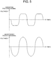
- Fig. 5 is an illustrative drawing showing an output waveform of the excitation circuit 11 of the rotation angle detection device 1 according to the second embodiment of the present invention.
- the first switching circuit 21 is off, there is a possibility of increased error in the detection accuracy of the resolver 10 caused by distortion of the output waveform of the operating amplifier in the excitation circuit 11, as illustrated in Fig. 5 , due to the fact that the output voltage of the power supply circuit 12 is set to a low voltage.
- the output voltage of the power supply circuit 12 is set to a low voltage in this way in cases where the motor generator is not performing a driving operation. Therefore, in cases such as this, the resolver detection accuracy is not required to be of the same level as during a driving operation of the motor generator, and therefore the distortion of the excitation signal has little effect on the detection accuracy of the resolver 10. Furthermore, when rotating idly, the motor generator rotates at a high number of revolutions, for example, about 1000 r/min, and therefore the effect of the distortion of the excitation signal on the detection accuracy of the resolver 10 is relatively small.
- the resolver detection accuracy is improved by raising the amplitude of the excitation signal in accordance with the output voltage of the power supply circuit, during a driving operation of the motor generator. Furthermore, when a driving operation of the motor generator is not being performed, the amount of heat generated by the resolver and the excitation circuit is suppressed by reducing the amplitude of the excitation signal in accordance with the output voltage of the power supply circuit.
- the first embodiment above describes a method which raises the amplitude of the excitation signal to improve the detection accuracy of the resolver 10 by switching the feedback resistance 20 of the operating amplifier of the excitation circuit 11.
- a third embodiment of the present invention describes a method which raises the frequency of the excitation signal to improve the detection accuracy of the resolver 10, by switching the resistance of the excitation circuit 11 which sets the transmission frequency of the excitation signal.
- FIG. 1 A block diagram illustrating the configuration of the rotation angle detection device 1 according to the third embodiment of the present invention is the same as Fig. 1 relating to the first embodiment described above.
- the third embodiment differs from the first embodiment described above in that the first switching circuit 21 switches the frequency of the excitation signal, rather than the size of the excitation signal.
- the remainder of the configuration is the same as Fig. 1 and therefore explanation thereof is omitted here.
- the first switching circuit 21 is provided in the excitation circuit 11, and is controlled to be switched on and off by the control of the control unit 23.
- the first switching circuit 21 switches a resistance (not illustrated) which sets the transmission frequency of the excitation circuit 11, to a fourth resistance.
- the first switching circuit 21 it is possible to use, for example, a circuit which is formed by serial connection of a transistor switch and a fourth resistance, and which is connected in parallel with the resistance which sets the transmission frequency of the excitation circuit 11.
- a circuit formed by parallel connection of a transistor switch and the fourth resistance may be connected in series with the resistance which sets the transmission frequency of the excitation circuit 11.
- the frequency when on of the excitation signal is set to a frequency value of the excitation signal by which the required value of the detection accuracy of the resolver 10 can be satisfied during a driving operation of the motor generator, taking the effects of the external magnetic flux into consideration.
- the frequency value when off of the excitation signal is set to a frequency value of the excitation signal which makes it possible to supress the amount of heat generated by the excitation circuit 11 and the resolver 10, while maintaining a detection accuracy of the resolver 10 by which information about the rotation speed of the motor generator can be obtained, when not performing a driving operation of the motor generator.
- the resistance value of the fourth resistance and the resistance value of the feedback resistance 20 are set such that the size of the frequency of the excitation signal applied to the excitation coil respectively becomes the frequency when on, and the frequency when off, taking the impedance characteristics of the excitation coil into consideration.
- the frequency of the excitation signal is required to have a sufficiently large value compared to the maximum value of the number of revolutions of the motor generator.
- the frequency when off can also be reduced, since it is sufficient to maintain a detection accuracy of the resolver 10 that enables information about the rotation speed of the motor generator to be obtained.
- the resolver detection accuracy is improved by raising the frequency of the excitation signal, during a driving operation of the motor generator. Furthermore, when a driving operation of the motor generator is not being performed, the amount of heat generated by the resolver and the excitation circuit is suppressed by reducing the frequency of the excitation signal.
- the first switching circuit 21 switches an existing resistance to the first resistance, the third resistance or the fourth resistance, when in an on state, but it is also possible to adopt a configuration wherein the first switching circuit 21 is provided with two resistances, a resistance for an on state and a resistance for an off state, and switches between these two resistances, when in the on state and the off state.
- the first switching circuit 21 when in the on state, the first switching circuit 21 is switched to the resistance for an on state which has a resistance value whereby the amplitude or frequency of the excitation signal becomes the amplitude value when on or the frequency when on described above, and when in the off state, the first switching circuit 21 is switched to the resistance for an off state which has a resistance value whereby the amplitude or frequency of the excitation signal becomes the amplitude value when off or the frequency when off described above.
Landscapes
- Physics & Mathematics (AREA)
- General Physics & Mathematics (AREA)
- Engineering & Computer Science (AREA)
- Power Engineering (AREA)
- Transmission And Conversion Of Sensor Element Output (AREA)
- Control Of Electric Motors In General (AREA)
Applications Claiming Priority (1)
| Application Number | Priority Date | Filing Date | Title |
|---|---|---|---|
| PCT/JP2014/079403 WO2016071980A1 (ja) | 2014-11-06 | 2014-11-06 | 回転角度検出装置および回転角度検出方法 |
Publications (3)
| Publication Number | Publication Date |
|---|---|
| EP3217150A1 true EP3217150A1 (de) | 2017-09-13 |
| EP3217150A4 EP3217150A4 (de) | 2018-06-20 |
| EP3217150B1 EP3217150B1 (de) | 2019-05-29 |
Family
ID=55908733
Family Applications (1)
| Application Number | Title | Priority Date | Filing Date |
|---|---|---|---|
| EP14905520.4A Not-in-force EP3217150B1 (de) | 2014-11-06 | 2014-11-06 | Vorrichtung zur drehwinkelerfassung und verfahren zur drehwinkelerfassung |
Country Status (5)
| Country | Link |
|---|---|
| US (1) | US10151605B2 (de) |
| EP (1) | EP3217150B1 (de) |
| JP (1) | JP6173612B2 (de) |
| CN (1) | CN107076577B (de) |
| WO (1) | WO2016071980A1 (de) |
Cited By (2)
| Publication number | Priority date | Publication date | Assignee | Title |
|---|---|---|---|---|
| DE102017217243B3 (de) | 2017-09-27 | 2018-09-13 | Deutsches Zentrum für Luft- und Raumfahrt e.V. | Resolver |
| EP3879693B1 (de) * | 2020-03-13 | 2024-11-20 | Hamilton Sundstrand Corporation | Nichtlineare trimmkopfstromversorgung mit grossem eingangsbereich und hohem wirkungsgrad |
Families Citing this family (1)
| Publication number | Priority date | Publication date | Assignee | Title |
|---|---|---|---|---|
| US12055390B2 (en) | 2022-03-30 | 2024-08-06 | Hamilton Sundstrand Corporation | Standalone resolver angle verification |
Family Cites Families (10)
| Publication number | Priority date | Publication date | Assignee | Title |
|---|---|---|---|---|
| JP3377050B2 (ja) * | 1993-02-12 | 2003-02-17 | 株式会社安川電機 | 絶対位置検出装置 |
| US6331759B1 (en) * | 1999-04-27 | 2001-12-18 | The Boeing Company | Pulse drive angle measurement system and method |
| JP3938902B2 (ja) * | 2002-11-27 | 2007-06-27 | 株式会社ジェイテクト | 角度検出装置及びそれを備えたトルクセンサ |
| CN101847501A (zh) * | 2009-03-25 | 2010-09-29 | 爱三工业株式会社 | 旋转变压器 |
| GB2481406B (en) * | 2010-06-22 | 2016-01-20 | Ametek Airtechnology Group Ltd | A resolver |
| JP5671920B2 (ja) * | 2010-10-04 | 2015-02-18 | 日産自動車株式会社 | モータ駆動装置 |
| JP5289420B2 (ja) | 2010-11-30 | 2013-09-11 | 三菱電機株式会社 | レゾルバ |
| JP5803428B2 (ja) * | 2011-08-25 | 2015-11-04 | 株式会社ジェイテクト | 回転センサ、及び回転角検出装置 |
| WO2015059911A1 (ja) * | 2013-10-21 | 2015-04-30 | パナソニックIpマネジメント株式会社 | 回転数検出装置 |
| JP2015145863A (ja) * | 2014-02-04 | 2015-08-13 | トヨタ自動車株式会社 | レゾルバ制御装置 |
-
2014
- 2014-11-06 WO PCT/JP2014/079403 patent/WO2016071980A1/ja not_active Ceased
- 2014-11-06 US US15/514,349 patent/US10151605B2/en active Active
- 2014-11-06 CN CN201480083057.0A patent/CN107076577B/zh not_active Expired - Fee Related
- 2014-11-06 EP EP14905520.4A patent/EP3217150B1/de not_active Not-in-force
- 2014-11-06 JP JP2016557391A patent/JP6173612B2/ja not_active Expired - Fee Related
Cited By (2)
| Publication number | Priority date | Publication date | Assignee | Title |
|---|---|---|---|---|
| DE102017217243B3 (de) | 2017-09-27 | 2018-09-13 | Deutsches Zentrum für Luft- und Raumfahrt e.V. | Resolver |
| EP3879693B1 (de) * | 2020-03-13 | 2024-11-20 | Hamilton Sundstrand Corporation | Nichtlineare trimmkopfstromversorgung mit grossem eingangsbereich und hohem wirkungsgrad |
Also Published As
| Publication number | Publication date |
|---|---|
| US10151605B2 (en) | 2018-12-11 |
| JP6173612B2 (ja) | 2017-08-02 |
| US20170276515A1 (en) | 2017-09-28 |
| CN107076577B (zh) | 2019-07-23 |
| EP3217150B1 (de) | 2019-05-29 |
| CN107076577A (zh) | 2017-08-18 |
| WO2016071980A1 (ja) | 2016-05-12 |
| EP3217150A4 (de) | 2018-06-20 |
| JPWO2016071980A1 (ja) | 2017-04-27 |
Similar Documents
| Publication | Publication Date | Title |
|---|---|---|
| US8405344B2 (en) | Method and apparatus for estimating a rotation speed of an electric motor | |
| JP6277796B2 (ja) | 電動ポンプ | |
| JP5824918B2 (ja) | インバータ制御装置及びインバータ制御方法 | |
| EP2770628B1 (de) | Sensorlose bürstenlose Gleichstrommotorcontroller mit variabler Verbindung für Raumanwendungen und gehärtete Anwendungen | |
| JP6361450B2 (ja) | 誘導電動機の制御装置 | |
| US9991785B2 (en) | Electric power converting device | |
| EP3217150B1 (de) | Vorrichtung zur drehwinkelerfassung und verfahren zur drehwinkelerfassung | |
| US7791911B2 (en) | Inverter device which maintains voltage during input voltage drop | |
| CN104852356B (zh) | 电动机的控制保护装置 | |
| JP2009536012A (ja) | 電気モータ、特にファンモータのコントロールユニット | |
| CN104682824B (zh) | 用于控制感应电动机的设备 | |
| US12404853B2 (en) | Electric oil pump for automobile transmission clutch engagement, electric oil pump control method for automobile transmission clutch engagement, vehicle, and vehicle electric oil pump for automobile transmission clutch engagement | |
| JP4674568B2 (ja) | モータインバータ | |
| WO2021117453A1 (ja) | 電動機の制御装置 | |
| JPWO2020096007A1 (ja) | 電力変換装置、圧送装置、制御方法、診断装置及び診断方法 | |
| JP2012075230A (ja) | ブラシレスモータの駆動制御装置 | |
| JP5807832B1 (ja) | 誘導電動機のための位相生成装置 | |
| CN203747714U (zh) | 用于麻醉机的无刷直流电机的控制装置 | |
| JP2021097436A (ja) | 電動機の制御装置 | |
| JP5092572B2 (ja) | 永久磁石形同期電動機の制御装置 | |
| KR100709816B1 (ko) | 영구자석식 동기 모터의 제어장치 | |
| JP6636852B2 (ja) | 電力変換装置 | |
| JP6123181B2 (ja) | モータ制御装置 | |
| JP2022049598A (ja) | モータの制御装置 | |
| JP2010279139A (ja) | モータ制御装置 |
Legal Events
| Date | Code | Title | Description |
|---|---|---|---|
| STAA | Information on the status of an ep patent application or granted ep patent |
Free format text: STATUS: THE INTERNATIONAL PUBLICATION HAS BEEN MADE |
|
| PUAI | Public reference made under article 153(3) epc to a published international application that has entered the european phase |
Free format text: ORIGINAL CODE: 0009012 |
|
| STAA | Information on the status of an ep patent application or granted ep patent |
Free format text: STATUS: REQUEST FOR EXAMINATION WAS MADE |
|
| 17P | Request for examination filed |
Effective date: 20170505 |
|
| AK | Designated contracting states |
Kind code of ref document: A1 Designated state(s): AL AT BE BG CH CY CZ DE DK EE ES FI FR GB GR HR HU IE IS IT LI LT LU LV MC MK MT NL NO PL PT RO RS SE SI SK SM TR |
|
| AX | Request for extension of the european patent |
Extension state: BA ME |
|
| DAX | Request for extension of the european patent (deleted) | ||
| A4 | Supplementary search report drawn up and despatched |
Effective date: 20180524 |
|
| RIC1 | Information provided on ipc code assigned before grant |
Ipc: G01D 5/20 20060101AFI20180517BHEP |
|
| GRAP | Despatch of communication of intention to grant a patent |
Free format text: ORIGINAL CODE: EPIDOSNIGR1 |
|
| STAA | Information on the status of an ep patent application or granted ep patent |
Free format text: STATUS: GRANT OF PATENT IS INTENDED |
|
| INTG | Intention to grant announced |
Effective date: 20181217 |
|
| GRAS | Grant fee paid |
Free format text: ORIGINAL CODE: EPIDOSNIGR3 |
|
| GRAA | (expected) grant |
Free format text: ORIGINAL CODE: 0009210 |
|
| STAA | Information on the status of an ep patent application or granted ep patent |
Free format text: STATUS: THE PATENT HAS BEEN GRANTED |
|
| AK | Designated contracting states |
Kind code of ref document: B1 Designated state(s): AL AT BE BG CH CY CZ DE DK EE ES FI FR GB GR HR HU IE IS IT LI LT LU LV MC MK MT NL NO PL PT RO RS SE SI SK SM TR |
|
| REG | Reference to a national code |
Ref country code: GB Ref legal event code: FG4D |
|
| REG | Reference to a national code |
Ref country code: CH Ref legal event code: EP |
|
| REG | Reference to a national code |
Ref country code: AT Ref legal event code: REF Ref document number: 1138539 Country of ref document: AT Kind code of ref document: T Effective date: 20190615 |
|
| REG | Reference to a national code |
Ref country code: DE Ref legal event code: R096 Ref document number: 602014047699 Country of ref document: DE |
|
| REG | Reference to a national code |
Ref country code: IE Ref legal event code: FG4D |
|
| REG | Reference to a national code |
Ref country code: NL Ref legal event code: MP Effective date: 20190529 |
|
| REG | Reference to a national code |
Ref country code: LT Ref legal event code: MG4D |
|
| PG25 | Lapsed in a contracting state [announced via postgrant information from national office to epo] |
Ref country code: NO Free format text: LAPSE BECAUSE OF FAILURE TO SUBMIT A TRANSLATION OF THE DESCRIPTION OR TO PAY THE FEE WITHIN THE PRESCRIBED TIME-LIMIT Effective date: 20190829 Ref country code: ES Free format text: LAPSE BECAUSE OF FAILURE TO SUBMIT A TRANSLATION OF THE DESCRIPTION OR TO PAY THE FEE WITHIN THE PRESCRIBED TIME-LIMIT Effective date: 20190529 Ref country code: PT Free format text: LAPSE BECAUSE OF FAILURE TO SUBMIT A TRANSLATION OF THE DESCRIPTION OR TO PAY THE FEE WITHIN THE PRESCRIBED TIME-LIMIT Effective date: 20190930 Ref country code: LT Free format text: LAPSE BECAUSE OF FAILURE TO SUBMIT A TRANSLATION OF THE DESCRIPTION OR TO PAY THE FEE WITHIN THE PRESCRIBED TIME-LIMIT Effective date: 20190529 Ref country code: HR Free format text: LAPSE BECAUSE OF FAILURE TO SUBMIT A TRANSLATION OF THE DESCRIPTION OR TO PAY THE FEE WITHIN THE PRESCRIBED TIME-LIMIT Effective date: 20190529 Ref country code: SE Free format text: LAPSE BECAUSE OF FAILURE TO SUBMIT A TRANSLATION OF THE DESCRIPTION OR TO PAY THE FEE WITHIN THE PRESCRIBED TIME-LIMIT Effective date: 20190529 Ref country code: AL Free format text: LAPSE BECAUSE OF FAILURE TO SUBMIT A TRANSLATION OF THE DESCRIPTION OR TO PAY THE FEE WITHIN THE PRESCRIBED TIME-LIMIT Effective date: 20190529 Ref country code: FI Free format text: LAPSE BECAUSE OF FAILURE TO SUBMIT A TRANSLATION OF THE DESCRIPTION OR TO PAY THE FEE WITHIN THE PRESCRIBED TIME-LIMIT Effective date: 20190529 |
|
| PG25 | Lapsed in a contracting state [announced via postgrant information from national office to epo] |
Ref country code: GR Free format text: LAPSE BECAUSE OF FAILURE TO SUBMIT A TRANSLATION OF THE DESCRIPTION OR TO PAY THE FEE WITHIN THE PRESCRIBED TIME-LIMIT Effective date: 20190830 Ref country code: RS Free format text: LAPSE BECAUSE OF FAILURE TO SUBMIT A TRANSLATION OF THE DESCRIPTION OR TO PAY THE FEE WITHIN THE PRESCRIBED TIME-LIMIT Effective date: 20190529 Ref country code: LV Free format text: LAPSE BECAUSE OF FAILURE TO SUBMIT A TRANSLATION OF THE DESCRIPTION OR TO PAY THE FEE WITHIN THE PRESCRIBED TIME-LIMIT Effective date: 20190529 Ref country code: BG Free format text: LAPSE BECAUSE OF FAILURE TO SUBMIT A TRANSLATION OF THE DESCRIPTION OR TO PAY THE FEE WITHIN THE PRESCRIBED TIME-LIMIT Effective date: 20190829 |
|
| REG | Reference to a national code |
Ref country code: AT Ref legal event code: MK05 Ref document number: 1138539 Country of ref document: AT Kind code of ref document: T Effective date: 20190529 |
|
| PG25 | Lapsed in a contracting state [announced via postgrant information from national office to epo] |
Ref country code: CZ Free format text: LAPSE BECAUSE OF FAILURE TO SUBMIT A TRANSLATION OF THE DESCRIPTION OR TO PAY THE FEE WITHIN THE PRESCRIBED TIME-LIMIT Effective date: 20190529 Ref country code: SK Free format text: LAPSE BECAUSE OF FAILURE TO SUBMIT A TRANSLATION OF THE DESCRIPTION OR TO PAY THE FEE WITHIN THE PRESCRIBED TIME-LIMIT Effective date: 20190529 Ref country code: EE Free format text: LAPSE BECAUSE OF FAILURE TO SUBMIT A TRANSLATION OF THE DESCRIPTION OR TO PAY THE FEE WITHIN THE PRESCRIBED TIME-LIMIT Effective date: 20190529 Ref country code: NL Free format text: LAPSE BECAUSE OF FAILURE TO SUBMIT A TRANSLATION OF THE DESCRIPTION OR TO PAY THE FEE WITHIN THE PRESCRIBED TIME-LIMIT Effective date: 20190529 Ref country code: DK Free format text: LAPSE BECAUSE OF FAILURE TO SUBMIT A TRANSLATION OF THE DESCRIPTION OR TO PAY THE FEE WITHIN THE PRESCRIBED TIME-LIMIT Effective date: 20190529 Ref country code: RO Free format text: LAPSE BECAUSE OF FAILURE TO SUBMIT A TRANSLATION OF THE DESCRIPTION OR TO PAY THE FEE WITHIN THE PRESCRIBED TIME-LIMIT Effective date: 20190529 Ref country code: AT Free format text: LAPSE BECAUSE OF FAILURE TO SUBMIT A TRANSLATION OF THE DESCRIPTION OR TO PAY THE FEE WITHIN THE PRESCRIBED TIME-LIMIT Effective date: 20190529 |
|
| PG25 | Lapsed in a contracting state [announced via postgrant information from national office to epo] |
Ref country code: IT Free format text: LAPSE BECAUSE OF FAILURE TO SUBMIT A TRANSLATION OF THE DESCRIPTION OR TO PAY THE FEE WITHIN THE PRESCRIBED TIME-LIMIT Effective date: 20190529 Ref country code: SM Free format text: LAPSE BECAUSE OF FAILURE TO SUBMIT A TRANSLATION OF THE DESCRIPTION OR TO PAY THE FEE WITHIN THE PRESCRIBED TIME-LIMIT Effective date: 20190529 |
|
| REG | Reference to a national code |
Ref country code: DE Ref legal event code: R097 Ref document number: 602014047699 Country of ref document: DE |
|
| PG25 | Lapsed in a contracting state [announced via postgrant information from national office to epo] |
Ref country code: TR Free format text: LAPSE BECAUSE OF FAILURE TO SUBMIT A TRANSLATION OF THE DESCRIPTION OR TO PAY THE FEE WITHIN THE PRESCRIBED TIME-LIMIT Effective date: 20190529 |
|
| PLBE | No opposition filed within time limit |
Free format text: ORIGINAL CODE: 0009261 |
|
| STAA | Information on the status of an ep patent application or granted ep patent |
Free format text: STATUS: NO OPPOSITION FILED WITHIN TIME LIMIT |
|
| PG25 | Lapsed in a contracting state [announced via postgrant information from national office to epo] |
Ref country code: PL Free format text: LAPSE BECAUSE OF FAILURE TO SUBMIT A TRANSLATION OF THE DESCRIPTION OR TO PAY THE FEE WITHIN THE PRESCRIBED TIME-LIMIT Effective date: 20190529 |
|
| 26N | No opposition filed |
Effective date: 20200303 |
|
| PG25 | Lapsed in a contracting state [announced via postgrant information from national office to epo] |
Ref country code: SI Free format text: LAPSE BECAUSE OF FAILURE TO SUBMIT A TRANSLATION OF THE DESCRIPTION OR TO PAY THE FEE WITHIN THE PRESCRIBED TIME-LIMIT Effective date: 20190529 |
|
| REG | Reference to a national code |
Ref country code: DE Ref legal event code: R119 Ref document number: 602014047699 Country of ref document: DE |
|
| REG | Reference to a national code |
Ref country code: CH Ref legal event code: PL |
|
| PG25 | Lapsed in a contracting state [announced via postgrant information from national office to epo] |
Ref country code: MC Free format text: LAPSE BECAUSE OF FAILURE TO SUBMIT A TRANSLATION OF THE DESCRIPTION OR TO PAY THE FEE WITHIN THE PRESCRIBED TIME-LIMIT Effective date: 20190529 Ref country code: LU Free format text: LAPSE BECAUSE OF NON-PAYMENT OF DUE FEES Effective date: 20191106 Ref country code: CH Free format text: LAPSE BECAUSE OF NON-PAYMENT OF DUE FEES Effective date: 20191130 Ref country code: LI Free format text: LAPSE BECAUSE OF NON-PAYMENT OF DUE FEES Effective date: 20191130 |
|
| REG | Reference to a national code |
Ref country code: BE Ref legal event code: MM Effective date: 20191130 |
|
| GBPC | Gb: european patent ceased through non-payment of renewal fee |
Effective date: 20191106 |
|
| PG25 | Lapsed in a contracting state [announced via postgrant information from national office to epo] |
Ref country code: IE Free format text: LAPSE BECAUSE OF NON-PAYMENT OF DUE FEES Effective date: 20191106 Ref country code: GB Free format text: LAPSE BECAUSE OF NON-PAYMENT OF DUE FEES Effective date: 20191106 Ref country code: DE Free format text: LAPSE BECAUSE OF NON-PAYMENT OF DUE FEES Effective date: 20200603 |
|
| PG25 | Lapsed in a contracting state [announced via postgrant information from national office to epo] |
Ref country code: BE Free format text: LAPSE BECAUSE OF NON-PAYMENT OF DUE FEES Effective date: 20191130 |
|
| PG25 | Lapsed in a contracting state [announced via postgrant information from national office to epo] |
Ref country code: CY Free format text: LAPSE BECAUSE OF FAILURE TO SUBMIT A TRANSLATION OF THE DESCRIPTION OR TO PAY THE FEE WITHIN THE PRESCRIBED TIME-LIMIT Effective date: 20190529 |
|
| PG25 | Lapsed in a contracting state [announced via postgrant information from national office to epo] |
Ref country code: IS Free format text: LAPSE BECAUSE OF FAILURE TO SUBMIT A TRANSLATION OF THE DESCRIPTION OR TO PAY THE FEE WITHIN THE PRESCRIBED TIME-LIMIT Effective date: 20190929 |
|
| PG25 | Lapsed in a contracting state [announced via postgrant information from national office to epo] |
Ref country code: MT Free format text: LAPSE BECAUSE OF FAILURE TO SUBMIT A TRANSLATION OF THE DESCRIPTION OR TO PAY THE FEE WITHIN THE PRESCRIBED TIME-LIMIT Effective date: 20190529 Ref country code: HU Free format text: LAPSE BECAUSE OF FAILURE TO SUBMIT A TRANSLATION OF THE DESCRIPTION OR TO PAY THE FEE WITHIN THE PRESCRIBED TIME-LIMIT; INVALID AB INITIO Effective date: 20141106 |
|
| PGFP | Annual fee paid to national office [announced via postgrant information from national office to epo] |
Ref country code: FR Payment date: 20211018 Year of fee payment: 8 |
|
| PG25 | Lapsed in a contracting state [announced via postgrant information from national office to epo] |
Ref country code: MK Free format text: LAPSE BECAUSE OF FAILURE TO SUBMIT A TRANSLATION OF THE DESCRIPTION OR TO PAY THE FEE WITHIN THE PRESCRIBED TIME-LIMIT Effective date: 20190529 |
|
| PG25 | Lapsed in a contracting state [announced via postgrant information from national office to epo] |
Ref country code: FR Free format text: LAPSE BECAUSE OF NON-PAYMENT OF DUE FEES Effective date: 20221130 |