EP3217355A1 - Verfahren und computerprogrammprodukte zur kalibrierung von stereobildgebungssystem durch verwendung eines planaren spiegels - Google Patents
Verfahren und computerprogrammprodukte zur kalibrierung von stereobildgebungssystem durch verwendung eines planaren spiegels Download PDFInfo
- Publication number
- EP3217355A1 EP3217355A1 EP16462003.1A EP16462003A EP3217355A1 EP 3217355 A1 EP3217355 A1 EP 3217355A1 EP 16462003 A EP16462003 A EP 16462003A EP 3217355 A1 EP3217355 A1 EP 3217355A1
- Authority
- EP
- European Patent Office
- Prior art keywords
- camera
- mirror
- image
- coordinate system
- images
- Prior art date
- Legal status (The legal status is an assumption and is not a legal conclusion. Google has not performed a legal analysis and makes no representation as to the accuracy of the status listed.)
- Withdrawn
Links
Images


Classifications
-
- G—PHYSICS
- G06—COMPUTING OR CALCULATING; COUNTING
- G06T—IMAGE DATA PROCESSING OR GENERATION, IN GENERAL
- G06T7/00—Image analysis
- G06T7/80—Analysis of captured images to determine intrinsic or extrinsic camera parameters, i.e. camera calibration
- G06T7/85—Stereo camera calibration
-
- G—PHYSICS
- G06—COMPUTING OR CALCULATING; COUNTING
- G06T—IMAGE DATA PROCESSING OR GENERATION, IN GENERAL
- G06T15/00—Three-dimensional [3D] image rendering
- G06T15/08—Volume rendering
-
- G—PHYSICS
- G06—COMPUTING OR CALCULATING; COUNTING
- G06T—IMAGE DATA PROCESSING OR GENERATION, IN GENERAL
- G06T7/00—Image analysis
- G06T7/50—Depth or shape recovery
- G06T7/55—Depth or shape recovery from multiple images
- G06T7/593—Depth or shape recovery from multiple images from stereo images
-
- G—PHYSICS
- G06—COMPUTING OR CALCULATING; COUNTING
- G06T—IMAGE DATA PROCESSING OR GENERATION, IN GENERAL
- G06T7/00—Image analysis
- G06T7/60—Analysis of geometric attributes
-
- G—PHYSICS
- G06—COMPUTING OR CALCULATING; COUNTING
- G06T—IMAGE DATA PROCESSING OR GENERATION, IN GENERAL
- G06T7/00—Image analysis
- G06T7/70—Determining position or orientation of objects or cameras
-
- H—ELECTRICITY
- H04—ELECTRIC COMMUNICATION TECHNIQUE
- H04N—PICTORIAL COMMUNICATION, e.g. TELEVISION
- H04N13/00—Stereoscopic video systems; Multi-view video systems; Details thereof
- H04N13/20—Image signal generators
- H04N13/204—Image signal generators using stereoscopic image cameras
- H04N13/207—Image signal generators using stereoscopic image cameras using a single two-dimensional [2D] image sensor
- H04N13/211—Image signal generators using stereoscopic image cameras using a single two-dimensional [2D] image sensor using temporal multiplexing
-
- H—ELECTRICITY
- H04—ELECTRIC COMMUNICATION TECHNIQUE
- H04N—PICTORIAL COMMUNICATION, e.g. TELEVISION
- H04N13/00—Stereoscopic video systems; Multi-view video systems; Details thereof
- H04N13/20—Image signal generators
- H04N13/204—Image signal generators using stereoscopic image cameras
- H04N13/207—Image signal generators using stereoscopic image cameras using a single two-dimensional [2D] image sensor
- H04N13/221—Image signal generators using stereoscopic image cameras using a single two-dimensional [2D] image sensor using the relative movement between cameras and objects
-
- H—ELECTRICITY
- H04—ELECTRIC COMMUNICATION TECHNIQUE
- H04N—PICTORIAL COMMUNICATION, e.g. TELEVISION
- H04N13/00—Stereoscopic video systems; Multi-view video systems; Details thereof
- H04N13/20—Image signal generators
- H04N13/204—Image signal generators using stereoscopic image cameras
- H04N13/207—Image signal generators using stereoscopic image cameras using a single two-dimensional [2D] image sensor
- H04N13/236—Image signal generators using stereoscopic image cameras using a single two-dimensional [2D] image sensor using varifocal lenses or mirrors
-
- H—ELECTRICITY
- H04—ELECTRIC COMMUNICATION TECHNIQUE
- H04N—PICTORIAL COMMUNICATION, e.g. TELEVISION
- H04N13/00—Stereoscopic video systems; Multi-view video systems; Details thereof
- H04N13/20—Image signal generators
- H04N13/204—Image signal generators using stereoscopic image cameras
- H04N13/246—Calibration of cameras
-
- H—ELECTRICITY
- H04—ELECTRIC COMMUNICATION TECHNIQUE
- H04N—PICTORIAL COMMUNICATION, e.g. TELEVISION
- H04N13/00—Stereoscopic video systems; Multi-view video systems; Details thereof
- H04N13/20—Image signal generators
- H04N13/282—Image signal generators for generating image signals corresponding to three or more geometrical viewpoints, e.g. multi-view systems
-
- G—PHYSICS
- G06—COMPUTING OR CALCULATING; COUNTING
- G06T—IMAGE DATA PROCESSING OR GENERATION, IN GENERAL
- G06T2207/00—Indexing scheme for image analysis or image enhancement
- G06T2207/10—Image acquisition modality
- G06T2207/10004—Still image; Photographic image
- G06T2207/10012—Stereo images
-
- G—PHYSICS
- G06—COMPUTING OR CALCULATING; COUNTING
- G06T—IMAGE DATA PROCESSING OR GENERATION, IN GENERAL
- G06T2207/00—Indexing scheme for image analysis or image enhancement
- G06T2207/10—Image acquisition modality
- G06T2207/10016—Video; Image sequence
- G06T2207/10021—Stereoscopic video; Stereoscopic image sequence
-
- G—PHYSICS
- G06—COMPUTING OR CALCULATING; COUNTING
- G06T—IMAGE DATA PROCESSING OR GENERATION, IN GENERAL
- G06T2207/00—Indexing scheme for image analysis or image enhancement
- G06T2207/10—Image acquisition modality
- G06T2207/10028—Range image; Depth image; 3D point clouds
-
- G—PHYSICS
- G06—COMPUTING OR CALCULATING; COUNTING
- G06T—IMAGE DATA PROCESSING OR GENERATION, IN GENERAL
- G06T2207/00—Indexing scheme for image analysis or image enhancement
- G06T2207/30—Subject of image; Context of image processing
- G06T2207/30244—Camera pose
Definitions
- the invention generally relates to the production of calibrated stereo images. More particularly, the present invention relates to methods of producing calibrated stereo images by using a planar mirror and computer program products to carry out the methods.
- the distance between a camera and a spatial point in a scene can be determined or well estimated from the position of the point within two or more associated images showing the same point, wherein either the scene is stationary or the associated images are captured simultaneously.
- the distance calculation is still possible if one or more planar mirrors are arranged in the scene, and some of the images are captured in the mirror.
- the three dimensional (3D) position of a point can be computed from basic geometric relationships when the relationship between the spatial position of the image recording device and the spatial position and specific parameters of the reflecting surfaces (e.g. mirrors) are known.
- the challenge in computing an unknown distance from multiple images using reflecting surfaces is called catadioptric stereo vision. In J. Gluckman and S.K.
- Calibrating a stereo (or multi-view) camera system is a difficult task. In general, it requires to find several corresponding points in the captured images, and then to solve a non-linear optimization problem with six to eight parameters (depending on whether or not the focal lengths of the cameras are known). In our proposed method, calibration can be obtained by reducing the aforementioned optimization problem to two independent, much simpler optimization problems, each having three or four parameters (depending on whether or not the focal lengths are known). Due to this decomposition of a more complex computation into two simpler computations, the method of the invention is faster, more reliable and more robust than the prior art calibration methods.
- the key idea of the calibration methods of the present invention is that by using the mirror view of the real camera along with multiple (different) views of an object in one or more captured images, the 3D coordinates of a point in the real space with respect to the mirror coordinate system can be easily determined. Additionally, by selecting two spatial points which both appear in the one or more captured images, the real distance between the two points can be determined on the basis of their corresponding image points.
- a method for calibrating a stereo imaging system by using at least one camera and a planar mirror comprising the steps of:
- the up-vector may be obtained by projecting a gravity vector on the mirror's plane or by selecting corresponding point pairs in the at least one image.
- a method for calibrating a stereo imaging system by using one camera and a planar mirror comprising the steps of:
- the camera is part of a camera device including any one of a mobile phone, a smart phone, a phablet, a tablet computer, a notebook, a digital camera or the like.
- a method of measuring a distance between two points of an object comprising the steps of:
- a method of depth estimation for an object comprising the steps of:
- a computer program product which includes computer-readable instructions that, when running on a computer, carry out the steps of the method according to the first aspect of the present invention.
- a computer program product which includes computer-readable instructions that, when running on a computer, carry out the steps of the method according to the second aspect of the present invention.
- image means the product of image capturing performed by an image recording device, such as an image sensor or a camera
- picture means a visual representation of an object or person within a captured image.
- An image may be a still image or a frame of a video sequence (also referred to as video image).
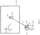
- FIG. 1 illustrates the coordinate systems used in the method of the present invention.
- a real camera device 100 has a Cartesian coordinate system K C having mutually orthogonal axes x C , y C and z C .
- the real camera device 100 comprises a real camera 110.
- the real camera device 100 may be any kind of processor-based device equipped with a camera or any sort of image sensor.
- the camera device 100 may include, for example, a mobile phone, a smart phone, a phablet, a tablet PC, a notebook, a digital camera, or the like, or any kind of other camera device capable for capturing an image.
- a planar mirror 140 also has a Cartesian coordinate system K M having mutually orthogonal axes x M , y M and z M , wherein axes x M and y M , and therefore the origo g of the coordinate system K M are all in the plane of the mirror 140.
- the real camera device 100 has a mirror view, called a virtual camera device 101 appearing behind the mirror.
- the virtual camera device 101 also has a virtual camera 111, which is a mirror view of the real camera 110.
- a vector m is defined to be perpendicular to the mirror 140 and to have a length which is equal to the distance between the mirror 140 and the real camera 110.
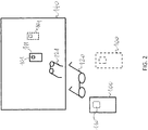
- calibration is based on the camera-mirror setup shown in Figure 2 .
- the real camera 110 captures multiple (at least two) images, each captured image showing only a mirror view (virtual object) 121 of a real object 120 and the virtual camera 111.
- the real object 120 can be within the field of view of the real camera 110 partly or entirely, it has no importance regarding the calibration procedure as only the points of the virtual objects are processed in the method of the invention according to its first aspect. It means that the real object may either be placed in a space volume between the real camera 100 and the mirror 140, or at a location that is farther from the mirror 140 than from the camera 100. In this latter case, the captured images do not contain the views of the real object 120 at all.
- the real camera device 100 has its camera 110 on its side facing the mirror 140 therefore the real camera 110 is depicted by dotted line in those Figures.
- two images I1 and I2 are shown for example, each one being captured at different camera positions.
- the virtual camera device has two pictures D1, D2, respectively, at different positions
- the virtual camera has two pictures C1, C2, respectively, at different positions
- the mirror view of the object i.e. the virtual object
- O1, 02 respectively, also at different positions.
- all of the images are preferably taken at different camera positions, while the relative position between the object and the mirror is assumed to be constant (in case of a stationary arrangement) or substantially constant (in case of a moving arrangement). If the images I1 and I2 are captured by two cameras simultaneously, the scene does not need to be stationary.
- step S200 at least two images are obtained using the aforementioned camera-mirror setup as shown in Figure 2 .
- Each of the images contains a mirror view of the real camera (i.e. the virtual camera) and a mirror view of an object.
- the image processing part of the method has the following four phases:
- the center of the pictures C1, C2 of the virtual cameras is first found in each of the images in step S206.
- M R t 0 0 0 1
- M is a complete homogenous transformation matrix
- R is a 3x3 rotation matrix
- t is a 3x1 translation vector
- n m ⁇ m ⁇
- m the vector pointing from the mirror to the camera and orthogonal to the mirror's plane. Consequently, ⁇ m ⁇ defines the distance between the mirror and the camera.
- the projection of the global vector u * onto the mirror's plane will result in an up-vector u of the mirror coordinate system K M .
- step S210 the distance between the mirror and the camera, i.e. the value of ⁇ m ⁇ is determined by calculating the aspect ratio of the camera in the image. To this end, the capturing focal length f of the camera is to be previously obtained in step S208.
- the focal length f of the camera is either a constant value and thus specified by the manufacturer of the camera or it is set by the user when capturing the images. In both cases, the focal length f of the camera is therefore assumed to be known.
- the above mentioned aspect ratio of the camera is defined as the ratio of the distance d u 1 , u 2 to the distance d U 1 , U 2 , wherein d u 1 , u 2 is the distance between two points u 1 , u 2 of the real camera device 100 and the d U 1 , U 2 is the distance between the respective points U 1 , U 2 of the picture of the virtual camera device (e.g. D1 in Figure 3 ).
- the distance is measured in the captured image in pixels, whereas the distance d U 1 , U 2 can be measured on the real camera device physically, for example in millimetre.
- a relative focal length H is to be obtained for the calculation of the vector m.
- Q be a point in the (either real or virtual) space and let p denote a respective pixel in the captured image.
- the pixel size s is a camera-specific parameter given by the manufacturer of the camera. Its value is typically about 1 micron.
- step S214 an up-vector u is defined for the mirror coordinate system K M in the following way.
- u * be any vector in the space.
- a possible selection for u * may be the gravity vector.
- Another option may be to select two points in the space with known distance from the mirror's plane. In this latter case one need to be able to find the corresponding pixels in the captured images. In fact it is not necessary to actually know this vector, it is only needed to know (or to calculate) its projection to the mirror plane, which vector is denoted by u.
- This projected vector u is regarded as the up-vector of the mirror coordinate system.
- the up-vector allows to define a coordinate transformation M** from the camera coordinate system to the mirror coordinate system in a more determined way, through setting the second column of the rotation matrix R to u. It is noted that at this point the rotation matrix R is entirely defined since the third column is the normalized mirror normal vector and the first column can be acquired from the principle of orthonormality.
- step S216 the origo of the mirror coordinate system K** M is determined. This can be done in several ways which will be introduced hereinafter.
- the origo of the mirror coordinate system is obtained by means of the free selection of a point in the space. Top this end, it is assumed that there is a point p at a known d distance from the mirror and this point is visible each of the at least one captured images. For example, this point may be selected as a mark on the mirror itself.
- the origo of the mirror coordinate system is considered to be the projection of this point p to the mirror's plane. Let the image pixel coordinates of the selected point p in the k-th image be p x k p y k , and let its distance from the mirror be d. Let g k be the base vector of the image ray.
- a second possible way of determining the origo of the mirror coordinate system is to select an arbitrary point in the mirror plane (e.g. the projection of the focal point of the camera), finding the associated image point in one of the captured images, and then finding a few further corresponding points in at least one other captured image.
- the origo of the mirror coordinate system can then be calculated by means of an optimization method (e.g. least mean square or the generalized Hough transform). It is noted that in this scheme, more than one associated point pair is needed for the calculations.
- a third possible way of determining the origo of the mirror coordinate system is to capture images I4, I5 by using two camera devices simultaneously in such a way that at least one of the images (without loss of generality let this be image 14) includes the pictures D1, D2' of the mirror views of both camera devices, while the other image (e.g. image 15) includes only the picture D2 of the mirror view of the second camera, as shown in Figure 9 .
- the images 14, I5 also show the pictures O1, 02 of the mirror view of an object.
- the projected points of the focal points of the cameras on the images are also known.
- the projected focal point of D2 be the common origo. Since the distance of D2 from the mirror and the pixel position of this point in image I4 is known, the translation to the common origo (the projection of D2 to the mirror plane) can be easily calculated for the first image.
- the coordinate transformation from the coordinate system of the image capturing camera into the mirror coordinate system is determined for each image in step S218.
- the advantage of the above described calibration method is that the coordinate transformation matrices M can be determined for each captured image separately, thus the calculation of the fundamental matrix F requires less computational force than in other known methods.
- the fundamental matrix F can be visualized by epipolar lines as shown in Figure 5 , in which the dashed lines of images I1 and I2 with the same letter are mutually corresponding epipolar lines. Accordingly, the corresponding epipolar line pairs in image I1 and image 12 are lines a1 and a2, respectively; lines b1 and b2, respectively; and lines c1 and c2, respectively. It means that any point in one of the images I1, I2 should belong to a real 3D point that has its picture on the other one of the images I1, I2 along the corresponding epipolar line (assuming that the mentioned point is not masked in the other images).
- the multiple views of the object is included within one image, wherein one of the views of the object is the picture of the real object and the other view of the object is its mirror view.
- the image shall also contain the mirror view of the capturing camera.
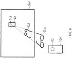
- calibration is based on the camera-mirror setup shown in Figure 6 .
- the real camera 110 captures both of the view and the mirror view of an object 120.
- the mirror view of the capturing camera device 100 with its camera 110 i.e. the virtual camera device 101 with its virtual camera 111
- the real object 120 shall be within the field of view of the real camera 110 at least partly.
- the real camera device 100 has its camera 110 on its side facing the mirror 140 therefore the real camera 110 is depicted by dotted line.
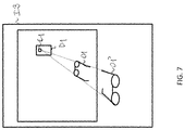
- FIG 7 an image 13 captured in the camera-mirror setup of Figure 6 is shown for example.
- the virtual camera device has a pictures D1
- the virtual camera has a picture C1
- the real object and the mirror view of the object i.e. the virtual object
- step S300 one image is obtained using the aforementioned camera-mirror setup as shown in Figure 6 .
- the captured image contains a picture of the mirror view of the real camera (i.e. the virtual camera), as well as pictures of the real view and the mirror view of an object.
- the image processing part of the method according to the second aspect of the present invention requires the only image processing phase of:
- an arbitrary mirror coordinate system is enough for the calibration of the camera-mirror setup shown in Figure 6 since only one image (i.e. image 13) is captured and consequently, it is not needed to determine a specific mirror coordinate system, which in the first aspect of the present invention was used to determine the coordinate transformations between the different camera coordinate systems.
- steps S306 to S312 correspond to steps S206 to S212 of the first method, respectively.
- step S306 the center of the picture C1 of the virtual camera is found in the image, then in step S308 the capturing focal length f of the camera is obtained, followed by the step S310, in which the distance between the mirror and the camera, i.e. the value of
- the mirror plane equation is obtained in step S312 on the basis of the captured image.
- the center of the picture C1 of the virtual camera is an epipole E of the stereo system defined by the real and virtual views of the object.
- a line v that connects the epipole E with any point V1 of the picture O1 of the real object in the image I3 also contains the corresponding point V2 of the picture 02 of the virtual object.
- ⁇ 1 c ⁇ d m T p 0 .
- ⁇ 2 ⁇ c ⁇ d m T q 0 .
- the coordinate transformation from the coordinate system of the image capturing camera into an arbitrary mirror coordinate system having an origo in the mirror's plane and a z-axis parallel to a normal vector of the mirror's plane can be determined in step S316.
- the distances between these points in the real 3D space can be calculated.
- the methods of the invention allow to determine real 3D coordinates of points which appear in any one of the at least one captured image.
- the methods of the invention can be further used, for example, to measure the distance between two points of an object, which are visible in at least two different views in the at least one captured image.
- the different views of the object may include, for example, two different mirror views in two captured images (cf. first aspect of the invention), or a real view and a mirror view of the object within one image (cf. second aspect of the invention).
- a method of measuring a distance between two points of an object comprising the steps of:
- a depth estimation for a captured object may be performed to generate a depth image of the object. Furthermore, once the stereo imaging system of the invention is calibrated through the above steps, the measurement of any kind of distances between two points becomes possible by finding associated point pairs in the at least one captured image.
- a method of depth estimation for an object comprising the steps of:
- the present invention also relates to a computer program product, which includes computer-readable instructions that, when running on a computer, carry out the above steps of the method according to the first aspect of the present invention.
- the present invention also relates to a computer program product, which includes computer-readable instructions that, when running on a computer, carry out the above steps of the method according to the second aspect of the present invention.
Landscapes
- Engineering & Computer Science (AREA)
- Multimedia (AREA)
- Signal Processing (AREA)
- Physics & Mathematics (AREA)
- General Physics & Mathematics (AREA)
- Theoretical Computer Science (AREA)
- Computer Vision & Pattern Recognition (AREA)
- Computer Graphics (AREA)
- Geometry (AREA)
- Length Measuring Devices By Optical Means (AREA)
- Image Processing (AREA)
- Image Analysis (AREA)
- Stereoscopic And Panoramic Photography (AREA)
Priority Applications (9)
| Application Number | Priority Date | Filing Date | Title |
|---|---|---|---|
| EP16462003.1A EP3217355A1 (de) | 2016-03-07 | 2016-03-07 | Verfahren und computerprogrammprodukte zur kalibrierung von stereobildgebungssystem durch verwendung eines planaren spiegels |
| US15/074,677 US10373337B2 (en) | 2016-03-07 | 2016-03-18 | Methods and computer program products for calibrating stereo imaging systems by using a planar mirror |
| CN201780028130.8A CN109155070A (zh) | 2016-03-07 | 2017-03-07 | 使用平面镜校准立体成像系统的方法和计算机程序产品 |
| PCT/HU2017/050006 WO2017153793A1 (en) | 2016-03-07 | 2017-03-07 | Methods and computer program products for calibrating stereo imaging systems by using a planar mirror |
| JP2018547935A JP2019510311A (ja) | 2016-03-07 | 2017-03-07 | 平面の鏡を用いたステレオ画像システムを較正するための方法およびコンピュータプログラム製品 |
| EP17713419.4A EP3427227B1 (de) | 2016-03-07 | 2017-03-07 | Verfahren und computerprogrammprodukte zur kalibrierung von stereobildgebungssystem durch verwendung eines planaren spiegels |
| US16/082,573 US10846885B2 (en) | 2016-03-07 | 2017-03-07 | Methods and computer program products for calibrating stereo imaging systems by using a planar mirror |
| ES17713419T ES2805425T3 (es) | 2016-03-07 | 2017-03-07 | Procedimientos y productos de programas informáticos para calibrar sistemas de imagen estéreo mediante el uso de un espejo plano |
| US16/448,876 US11010925B2 (en) | 2016-03-07 | 2019-06-21 | Methods and computer program products for calibrating stereo imaging systems by using a planar mirror |
Applications Claiming Priority (1)
| Application Number | Priority Date | Filing Date | Title |
|---|---|---|---|
| EP16462003.1A EP3217355A1 (de) | 2016-03-07 | 2016-03-07 | Verfahren und computerprogrammprodukte zur kalibrierung von stereobildgebungssystem durch verwendung eines planaren spiegels |
Publications (1)
| Publication Number | Publication Date |
|---|---|
| EP3217355A1 true EP3217355A1 (de) | 2017-09-13 |
Family
ID=55699597
Family Applications (2)
| Application Number | Title | Priority Date | Filing Date |
|---|---|---|---|
| EP16462003.1A Withdrawn EP3217355A1 (de) | 2016-03-07 | 2016-03-07 | Verfahren und computerprogrammprodukte zur kalibrierung von stereobildgebungssystem durch verwendung eines planaren spiegels |
| EP17713419.4A Not-in-force EP3427227B1 (de) | 2016-03-07 | 2017-03-07 | Verfahren und computerprogrammprodukte zur kalibrierung von stereobildgebungssystem durch verwendung eines planaren spiegels |
Family Applications After (1)
| Application Number | Title | Priority Date | Filing Date |
|---|---|---|---|
| EP17713419.4A Not-in-force EP3427227B1 (de) | 2016-03-07 | 2017-03-07 | Verfahren und computerprogrammprodukte zur kalibrierung von stereobildgebungssystem durch verwendung eines planaren spiegels |
Country Status (6)
| Country | Link |
|---|---|
| US (3) | US10373337B2 (de) |
| EP (2) | EP3217355A1 (de) |
| JP (1) | JP2019510311A (de) |
| CN (1) | CN109155070A (de) |
| ES (1) | ES2805425T3 (de) |
| WO (1) | WO2017153793A1 (de) |
Cited By (1)
| Publication number | Priority date | Publication date | Assignee | Title |
|---|---|---|---|---|
| CN113205555A (zh) * | 2021-05-28 | 2021-08-03 | 上海扩博智能技术有限公司 | 保持叶片位于相机视野中间的方法、系统、设备和存储介质 |
Families Citing this family (17)
| Publication number | Priority date | Publication date | Assignee | Title |
|---|---|---|---|---|
| JP2016125956A (ja) * | 2015-01-07 | 2016-07-11 | ソニー株式会社 | 情報処理装置、情報処理方法、および情報処理システム |
| EP3217355A1 (de) | 2016-03-07 | 2017-09-13 | Lateral Reality Kft. | Verfahren und computerprogrammprodukte zur kalibrierung von stereobildgebungssystem durch verwendung eines planaren spiegels |
| CN109300163B (zh) * | 2018-09-14 | 2021-09-24 | 高新兴科技集团股份有限公司 | 室内全景相机的空间标定方法、存储介质及电子设备 |
| CN111275766B (zh) * | 2018-12-05 | 2023-09-05 | 杭州海康威视数字技术股份有限公司 | 图像坐标系与gps坐标系的标定方法、装置及摄像机 |
| CN109886879B (zh) * | 2019-02-19 | 2022-11-01 | 广东建星建造第一工程有限公司 | 图形镜像处理方法、电子设备及存储介质 |
| CN109934878B (zh) * | 2019-03-25 | 2020-11-27 | 合肥工业大学 | 一种基于相机坐标系的线性标定系统及其方法 |
| CN112180362B (zh) * | 2019-07-05 | 2024-04-23 | 北京地平线机器人技术研发有限公司 | 雷达与相机之间的转换位姿确定方法、装置以及电子设备 |
| CN111028299A (zh) * | 2020-02-18 | 2020-04-17 | 吴怡锦 | 基于图像中点属性数据集计算标定点空间距的系统和方法 |
| CN111369447B (zh) * | 2020-03-09 | 2023-06-16 | 湖南警察学院 | 单目立体视觉图像中图像点的矫正方法 |
| US11282233B1 (en) * | 2020-09-08 | 2022-03-22 | Weta Digital Limited | Motion capture calibration |
| CN112258586B (zh) * | 2020-10-16 | 2022-10-21 | 中国石油大学(华东) | 一种面向单平面镜立体视觉模型参数的标定方法 |
| DE102020214248A1 (de) * | 2020-11-12 | 2022-05-12 | Robert Bosch Gesellschaft mit beschränkter Haftung | Verfahren zum Bereitstellen von Verformungsdaten für eine Verformungsanalyse, Verfahren zum Steuern einer Verformungsanalyse, Verfahren zum Herstellen zumindest eines vordefinierten punktsymmetrischen Bereichs und Vorrichtung |
| US11330021B1 (en) * | 2020-12-31 | 2022-05-10 | Benjamin Slotznick | System and method of mirroring a display of multiple video feeds in videoconferencing systems |
| US11621979B1 (en) | 2020-12-31 | 2023-04-04 | Benjamin Slotznick | Method and apparatus for repositioning meeting participants within a virtual space view in an online meeting user interface based on gestures made by the meeting participants |
| US11546385B1 (en) | 2020-12-31 | 2023-01-03 | Benjamin Slotznick | Method and apparatus for self-selection by participant to display a mirrored or unmirrored video feed of the participant in a videoconferencing platform |
| CN116051647B (zh) * | 2022-08-08 | 2024-06-25 | 荣耀终端有限公司 | 一种相机标定方法和电子设备 |
| CN118864735B (zh) * | 2024-09-25 | 2025-01-03 | 常州微亿智造科技有限公司 | 一种高反射面物体三维点云重建的方法 |
Citations (1)
| Publication number | Priority date | Publication date | Assignee | Title |
|---|---|---|---|---|
| EP2866446A1 (de) * | 2013-10-28 | 2015-04-29 | Lateral Reality Kft. | Verfahren und tragbare Multi-Kamera-Vorrichtung zur Herstellung von Stereobildern |
Family Cites Families (24)
| Publication number | Priority date | Publication date | Assignee | Title |
|---|---|---|---|---|
| US8189100B2 (en) * | 2006-07-25 | 2012-05-29 | Qualcomm Incorporated | Mobile device with dual digital camera sensors and methods of using the same |
| US8929645B2 (en) * | 2007-04-24 | 2015-01-06 | 21 Ct, Inc. | Method and system for fast dense stereoscopic ranging |
| US8723928B2 (en) * | 2008-07-11 | 2014-05-13 | Panasonic Corporation | Three-dimensional shape measuring apparatus, integrated circuit, and three-dimensional shape measuring method |
| CN101577002B (zh) * | 2009-06-16 | 2011-12-28 | 天津理工大学 | 应用于目标检测的鱼眼镜头成像系统标定方法 |
| US20110007205A1 (en) * | 2009-07-08 | 2011-01-13 | Dechnia, LLC | Rear to forward facing camera adapter |
| KR101055411B1 (ko) * | 2010-03-12 | 2011-08-09 | 이상원 | 입체 영상 생성 방법 및 그 장치 |
| US8908015B2 (en) * | 2010-03-24 | 2014-12-09 | Appcessories Llc | Apparatus and method for producing images for stereoscopic viewing |
| CN101923730B (zh) * | 2010-09-21 | 2012-05-02 | 北京大学 | 基于鱼眼相机和多平面镜装置的三维重建方法 |
| US8896667B2 (en) * | 2010-10-25 | 2014-11-25 | Aptina Imaging Corporation | Stereoscopic imaging systems with convergence control for reducing conflicts between accomodation and convergence |
| US10200671B2 (en) * | 2010-12-27 | 2019-02-05 | 3Dmedia Corporation | Primary and auxiliary image capture devices for image processing and related methods |
| US9230325B2 (en) * | 2011-08-19 | 2016-01-05 | University Of Rochester | Three-dimensional model acquisition using planar mirrors |
| EP2615580B1 (de) * | 2012-01-13 | 2016-08-17 | Softkinetic Software | Automatische Szenenkalibrierung |
| CN103177442A (zh) * | 2013-03-04 | 2013-06-26 | 北京邮电大学 | 一种无重叠视场的相机与二维激光的标定方法 |
| US9749541B2 (en) * | 2013-04-16 | 2017-08-29 | Tout Inc. | Method and apparatus for displaying and recording images using multiple image capturing devices integrated into a single mobile device |
| CA2819956C (en) * | 2013-07-02 | 2022-07-12 | Guy Martin | High accuracy camera modelling and calibration method |
| US20150103146A1 (en) * | 2013-10-16 | 2015-04-16 | Qualcomm Incorporated | Conversion of at least one non-stereo camera into a stereo camera |
| KR102033309B1 (ko) | 2013-10-25 | 2019-10-17 | 현대모비스 주식회사 | 운전석 위치를 고려하는 빔 포밍 마이크 제어 장치 및 방법 |
| US9615081B2 (en) * | 2013-10-28 | 2017-04-04 | Lateral Reality Kft. | Method and multi-camera portable device for producing stereo images |
| JP2015191186A (ja) * | 2014-03-28 | 2015-11-02 | 富士通株式会社 | ステレオアダプタ及びステレオ撮像装置 |
| CN104200477B (zh) * | 2014-09-11 | 2018-04-06 | 云南大学 | 基于空间平行圆求解平面折反射摄像机内参数的方法 |
| CN104284177A (zh) * | 2014-10-28 | 2015-01-14 | 天津大学 | 会聚立体图像视差控制方法 |
| CN105321174B (zh) * | 2015-09-23 | 2019-03-26 | 浙江大学 | 一种多平面镜反射跟踪云台系统标定方法 |
| EP3217355A1 (de) * | 2016-03-07 | 2017-09-13 | Lateral Reality Kft. | Verfahren und computerprogrammprodukte zur kalibrierung von stereobildgebungssystem durch verwendung eines planaren spiegels |
| US9930320B2 (en) * | 2016-05-04 | 2018-03-27 | Apple Inc. | Resolving three dimensional spatial information using time-shared structured lighting that embeds digital communication |
-
2016
- 2016-03-07 EP EP16462003.1A patent/EP3217355A1/de not_active Withdrawn
- 2016-03-18 US US15/074,677 patent/US10373337B2/en active Active
-
2017
- 2017-03-07 CN CN201780028130.8A patent/CN109155070A/zh active Pending
- 2017-03-07 ES ES17713419T patent/ES2805425T3/es active Active
- 2017-03-07 JP JP2018547935A patent/JP2019510311A/ja active Pending
- 2017-03-07 US US16/082,573 patent/US10846885B2/en not_active Expired - Fee Related
- 2017-03-07 EP EP17713419.4A patent/EP3427227B1/de not_active Not-in-force
- 2017-03-07 WO PCT/HU2017/050006 patent/WO2017153793A1/en not_active Ceased
-
2019
- 2019-06-21 US US16/448,876 patent/US11010925B2/en not_active Expired - Fee Related
Patent Citations (1)
| Publication number | Priority date | Publication date | Assignee | Title |
|---|---|---|---|---|
| EP2866446A1 (de) * | 2013-10-28 | 2015-04-29 | Lateral Reality Kft. | Verfahren und tragbare Multi-Kamera-Vorrichtung zur Herstellung von Stereobildern |
Non-Patent Citations (3)
| Title |
|---|
| HU ET AL., MULTIPLE-VIEW 3-D RECONSTRUCTION USING A MIRROR, Retrieved from the Internet <URL:ftp://ftp.cs.rochester.edu/pub/papers/robotics/05.tr863.Multiple-view 3-d reconstruction using a mirror.pdf> |
| J. GLUCKMAN; S.K. NAYAR: "Catadioptric Stereo Using Planar Mirrors", INTERNATIONAL JOURNAL ON COMPUTER VISION, vol. 44, no. 1, August 2001 (2001-08-01), pages 65 - 79, XP055108338, DOI: doi:10.1023/A:1011172403203 |
| RUI YU ET AL: "Real-Time Camera Pose Estimation Based on Multiple Planar Markers", IMAGE AND GRAPHICS, 2009. ICIG '09. FIFTH INTERNATIONAL CONFERENCE ON, IEEE, PISCATAWAY, NJ, USA, 20 September 2009 (2009-09-20), pages 640 - 645, XP031652834, ISBN: 978-1-4244-5237-8 * |
Cited By (2)
| Publication number | Priority date | Publication date | Assignee | Title |
|---|---|---|---|---|
| CN113205555A (zh) * | 2021-05-28 | 2021-08-03 | 上海扩博智能技术有限公司 | 保持叶片位于相机视野中间的方法、系统、设备和存储介质 |
| CN113205555B (zh) * | 2021-05-28 | 2023-09-19 | 上海扩博智能技术有限公司 | 保持叶片位于相机视野中间的方法、系统、设备和存储介质 |
Also Published As
| Publication number | Publication date |
|---|---|
| US10846885B2 (en) | 2020-11-24 |
| US11010925B2 (en) | 2021-05-18 |
| JP2019510311A (ja) | 2019-04-11 |
| US10373337B2 (en) | 2019-08-06 |
| EP3427227A1 (de) | 2019-01-16 |
| WO2017153793A1 (en) | 2017-09-14 |
| US20170256042A1 (en) | 2017-09-07 |
| US20190311497A1 (en) | 2019-10-10 |
| CN109155070A (zh) | 2019-01-04 |
| US20190043221A1 (en) | 2019-02-07 |
| EP3427227B1 (de) | 2020-04-22 |
| ES2805425T3 (es) | 2021-02-12 |
Similar Documents
| Publication | Publication Date | Title |
|---|---|---|
| US11010925B2 (en) | Methods and computer program products for calibrating stereo imaging systems by using a planar mirror | |
| US10334168B2 (en) | Threshold determination in a RANSAC algorithm | |
| JP2874710B2 (ja) | 三次元位置計測装置 | |
| US9972120B2 (en) | Systems and methods for geometrically mapping two-dimensional images to three-dimensional surfaces | |
| EP2597597A2 (de) | Vorrichtung und Verfahren zur Berechnung dreidimensionaler (3D) Positionen von Merkmalspunkten | |
| EP3903229B1 (de) | System und verfahren zur erkennung geometrischer formen | |
| US20190080464A1 (en) | Stereo matching method and apparatus | |
| Liu et al. | Epipolar rectification method for a stereovision system with telecentric cameras | |
| JP7298687B2 (ja) | 物体認識装置及び物体認識方法 | |
| Borghese et al. | Calibrating a video camera pair with a rigid bar | |
| Bergström et al. | Virtual projective shape matching in targetless CAD-based close-range photogrammetry for efficient estimation of specific deviations | |
| Svoboda et al. | Matching in catadioptric images with appropriate windows, and outliers removal | |
| Lim et al. | Virtual camera rectification with geometrical approach on single-lens stereovision using a biprism | |
| JPWO2020075213A1 (ja) | 計測装置、計測方法および顕微鏡システム | |
| EP2866446B1 (de) | Verfahren und tragbare Multi-Kamera-Vorrichtung zur Herstellung von Stereobildern | |
| Iqbal et al. | Real time 3D depth estimation and measurement of un-calibrated stereo and thermal images | |
| Cheng et al. | A linear approach for depth and colour camera calibration using hybrid parameters | |
| Godding et al. | 4D Surface matching for high-speed stereo sequences | |
| Bergamini et al. | Fundamental Matrix: Digital Camera calibration and Essential Matrix parameters | |
| Harvent et al. | Shape measurement using a new 3d-dic algorithm that preserves sharp edges | |
| Arnspang et al. | Relating scene depth to image ratios | |
| Guerchouche et al. | Accurate camera calibration algorithm using a robust estimation of the perspective projection matrix | |
| Agarwal et al. | A Device to Develop Depth Map Using Principles of Stereoscopic Vision | |
| Herráez et al. | Epipolar image rectification through geometric algorithms with unknown parameters | |
| Leotta et al. | 3D Slit Scanning with Planar Constraints★ |
Legal Events
| Date | Code | Title | Description |
|---|---|---|---|
| PUAI | Public reference made under article 153(3) epc to a published international application that has entered the european phase |
Free format text: ORIGINAL CODE: 0009012 |
|
| AK | Designated contracting states |
Kind code of ref document: A1 Designated state(s): AL AT BE BG CH CY CZ DE DK EE ES FI FR GB GR HR HU IE IS IT LI LT LU LV MC MK MT NL NO PL PT RO RS SE SI SK SM TR |
|
| AX | Request for extension of the european patent |
Extension state: BA ME |
|
| STAA | Information on the status of an ep patent application or granted ep patent |
Free format text: STATUS: THE APPLICATION IS DEEMED TO BE WITHDRAWN |
|
| 18D | Application deemed to be withdrawn |
Effective date: 20180314 |