EP3217497B1 - Support d'appareil - Google Patents
Support d'appareil Download PDFInfo
- Publication number
- EP3217497B1 EP3217497B1 EP16159269.6A EP16159269A EP3217497B1 EP 3217497 B1 EP3217497 B1 EP 3217497B1 EP 16159269 A EP16159269 A EP 16159269A EP 3217497 B1 EP3217497 B1 EP 3217497B1
- Authority
- EP
- European Patent Office
- Prior art keywords
- carrier
- housing
- connection
- duct
- realized
- Prior art date
- Legal status (The legal status is an assumption and is not a legal conclusion. Google has not performed a legal analysis and makes no representation as to the accuracy of the status listed.)
- Active
Links
Images


Classifications
-
- H—ELECTRICITY
- H02—GENERATION; CONVERSION OR DISTRIBUTION OF ELECTRIC POWER
- H02G—INSTALLATION OF ELECTRIC CABLES OR LINES, OR OF COMBINED OPTICAL AND ELECTRIC CABLES OR LINES
- H02G3/00—Installations of electric cables or lines or protective tubing therefor in or on buildings, equivalent structures or vehicles
- H02G3/02—Details
- H02G3/08—Distribution boxes; Connection or junction boxes
- H02G3/10—Distribution boxes; Connection or junction boxes for surface mounting on a wall
- H02G3/105—Distribution boxes; Connection or junction boxes for surface mounting on a wall in association with a plinth, channel, raceway or similar
-
- H—ELECTRICITY
- H02—GENERATION; CONVERSION OR DISTRIBUTION OF ELECTRIC POWER
- H02G—INSTALLATION OF ELECTRIC CABLES OR LINES, OR OF COMBINED OPTICAL AND ELECTRIC CABLES OR LINES
- H02G3/00—Installations of electric cables or lines or protective tubing therefor in or on buildings, equivalent structures or vehicles
- H02G3/30—Installations of cables or lines on walls, floors or ceilings
- H02G3/34—Installations of cables or lines on walls, floors or ceilings using separate protective tubing
-
- E—FIXED CONSTRUCTIONS
- E04—BUILDING
- E04F—FINISHING WORK ON BUILDINGS, e.g. STAIRS, FLOORS
- E04F17/00—Vertical ducts; Channels, e.g. for drainage
- E04F17/08—Vertical ducts; Channels, e.g. for drainage for receiving utility lines, e.g. cables, pipes
-
- E—FIXED CONSTRUCTIONS
- E04—BUILDING
- E04F—FINISHING WORK ON BUILDINGS, e.g. STAIRS, FLOORS
- E04F19/00—Other details of constructional parts for finishing work on buildings
- E04F19/02—Borders; Finishing strips, e.g. beadings; Light coves
- E04F19/04—Borders; Finishing strips, e.g. beadings; Light coves for use between floor or ceiling and wall, e.g. skirtings
- E04F2019/044—Borders; Finishing strips, e.g. beadings; Light coves for use between floor or ceiling and wall, e.g. skirtings with conduits
-
- H—ELECTRICITY
- H02—GENERATION; CONVERSION OR DISTRIBUTION OF ELECTRIC POWER
- H02G—INSTALLATION OF ELECTRIC CABLES OR LINES, OR OF COMBINED OPTICAL AND ELECTRIC CABLES OR LINES
- H02G3/00—Installations of electric cables or lines or protective tubing therefor in or on buildings, equivalent structures or vehicles
- H02G3/02—Details
- H02G3/06—Joints for connecting lengths of protective tubing or channels, to each other or to casings, e.g. to distribution boxes; Ensuring electrical continuity in the joint
- H02G3/0608—Joints for connecting non cylindrical conduits, e.g. channels
-
- H—ELECTRICITY
- H02—GENERATION; CONVERSION OR DISTRIBUTION OF ELECTRIC POWER
- H02G—INSTALLATION OF ELECTRIC CABLES OR LINES, OR OF COMBINED OPTICAL AND ELECTRIC CABLES OR LINES
- H02G3/00—Installations of electric cables or lines or protective tubing therefor in or on buildings, equivalent structures or vehicles
- H02G3/02—Details
- H02G3/08—Distribution boxes; Connection or junction boxes
- H02G3/086—Assembled boxes
Definitions
- the present invention relates to a device carrier for the assembly of electrical installation devices in addition to cable routing ducts designed in particular as a skirting board duct, with a carrier base for receiving at least one electrical installation device, a carrier housing for receiving the carrier base and a duct adapter for connecting the housing to the cable routing duct, the duct adapter being designed independently of the carrier housing and wherein the support housing has a recess in a housing wall on a connection side for connection to the duct adapter for receiving a connection device formed on a connection side of the duct adapter, with both a longitudinal side and a transverse side of the support housing being formed as a connection side, each of which has an in have the housing wall insert arranged in the recess of the housing wall.
- Device carriers of the type mentioned are used in particular for the attachment of sockets and switches to wiring ducts, which are used to install electrical wiring.
- Such a Overhead installation which is regularly required in existing buildings for cable installation and power supply of subsequently installed electrical consumers, are often designed as so-called baseboard ducts, which in a dual function allow the simultaneous formation of baseboards or baseboards in addition to an encased arrangement of the supply cables.
- a device carrier of the type mentioned, which allows a wall installation next to a baseboard channel is, for example, from DE 20 2004 013 181 U1 known.
- the carrier housing of the device carrier is designed in such a way that it simultaneously covers a carrier base with the electrical installation devices arranged therein and also a part of the skirting board channel adjacent to the device carrier.
- the known equipment carrier has a carrier housing with a convex front side, which extends with its part covering the skirting board channel over a channel cover which is arranged on a channel base and has a planar front side.
- the DE 20 2004 013 181 U1 a combination of an equipment carrier with a skirting trunking, in which the different external design of the carrier housing and the trunking cover is obvious.
- the EP 1 005 127 A1 the EP 0 929 138 A1 , the EP 1 571 744 A1 , the FR 2 786 617 A1 , the EP 1 326 315 and the GB 2 329 533 A devices are known for mounting on a cable trunking.
- the present invention is based on the object of proposing a device support which, in a particularly simple manner, enables a combination of the device support which appears harmonious in its external design with the cable routing duct, which is preferably designed as a skirting board duct, in order to also meet special aesthetic requirements with as little effort as possible and in particular increases the acceptance of a cost installation.
- the device carrier according to the invention has the features of claim 1 .
- the duct adapter is designed independently of the carrier housing, so that the external appearance of the device carrier can be adapted to the cable routing duct, which is preferably designed as a skirting board duct, simply by selecting a duct adapter that is adapted to the external design of the cable duct, i.e. in particular the duct cover.
- This makes it possible to match the duct cover of the cable duct and the duct adapter to one another in a suitable manner, with standard components being able to be used for the equipment carrier housing and a duct base of the cable duct.
- the configuration of the device carrier according to the invention contributes to a significant increase in the acceptance of the subsequent installation of cable duct systems in existing buildings of the most diverse epochs and architectural styles.
- the duct adapter forms a cover for a duct base of the cable routing duct designed for wall mounting, so that the duct adapter even in an area immediately adjacent to the equipment rack forms the duct cover and is thus a quasi-part of the duct cover of the cable routing duct. This enables a particularly high degree of optical integration of the device mount into the duct cover of the cable routing duct.
- channel adapter is interchangeably connected to the carrier housing, not only is handling of the channel adapter independent of the carrier housing possible, but also handling of the carrier housing together with the channel adapter as an assembly unit, so that the channel adapter can be designed separately compared to that known from the prior art in the support housing integrated design of the channel adapter does not increase the assembly effort.
- a particularly simple and convenient way of connecting the channel adapter and the carrier housing is possible if the channel adapter is connected to the carrier housing by means of a plug connection.
- the carrier housing has a recess on a connection side for connection to the channel adapter in a housing wall for receiving a connection device formed on a connection side of the channel adapter, so that a particularly compact connection between the carrier housing and the channel adapter is possible despite the configuration of the channel adapter being independent of the carrier housing ,
- the connection device of the channel adapter forms a wall component of the housing wall of the carrier housing.
- the recess formed on the connection side of the support housing is provided with a housing wall insert that can be exchanged for the connection device formed on the connection side of the duct adapter, so that, if necessary, the support housing can also be used independently of the duct adapter, in which case the wall recess is closed by the housing wall insert and thus an electrically secure covering of the electrical installation devices accommodated in the device carrier, ie for example sockets or switches, is possible, enclosing the carrier base on all sides.
- both a longitudinal side and a transverse side of the support housing are designed as a connection side, each of which has a housing wall insert arranged in a recess in a housing wall, so that the support housing can be connected to the duct adapter on different connection sides in basically the same way.
- both a long side and a short side of the carrier base are provided with a positioning aid that can be separated from the long side and the short side via a predetermined breaking device.
- This positioning aid has a parallel stop at a defined distance from the long side and the short side to rest against the cable routing duct, which means that, by means of the positioning aid, a defined parallel alignment of the support base is essential when mounting the support base on the wall, either with a vertical alignment or with a horizontal alignment can be simplified.
- the plug-in connection is designed as an engagement connection, such that a connecting web designed on the connecting device engages in a receiving groove designed at the opening edge of the recess, so that a particularly wide connection base can be formed.
- the connecting web and the receiving groove have a U-shaped extension such that a web section and groove section arranged adjacent to a front side of the carrier housing or the channel adapter and parallel to the front side together form an axial stop, so that not only over the U-shaped course of the engagement connection between the carrier housing and the channel adapter, a particularly resilient connection is created between the carrier housing and the channel adapter, but in addition the parallel web section and the parallel groove section form an axial stop which defines a flush relative arrangement of the front sides of the Allows channel adapter and the carrier housing.
- the support base serves to arrange or accommodate the electrical installation devices, which are covered with the support housing after they have been arranged in the support base.
- the support base has a connection device for connecting a mounting frame, such as this that for receiving the electrical installation device in the support base of the mounting frame can be connected together with the electrical installation device as a mounting unit with the connection device.
- the mounting frame is provided with a frame cover such that an opening edge of the carrier housing is between the mounting frame and the frame panel is added.
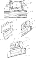
- the equipment carrier 10 has a carrier housing 14 and a duct adapter 15 connected to the carrier housing 14 and covering a front side 16 of a duct cover 18 mounted on a duct base 17 .
- the duct cover 18 has two cover elements 19, 20, each arranged laterally adjacent to the duct adapter 15, which are each partially covered by an adapter edge 21, 22 and serve to form a cable bushing 23, from which, not shown in detail, in the duct base 17 running lines from the channel base 17 are guided into the equipment rack 10 inside.
- the device carrier 10 in a horizontal orientation, in which the device carrier 10 is arranged on the cable routing duct 11 .
- the carrier housing 14 of the device carrier 10 is connected to a channel adapter 24, which deviates from the channel adapter 15, which is on a transverse side 25 of the carrier housing 14 is arranged on a longitudinal side 26 of the carrier housing 14 is arranged.
- connection cheeks 31 provided with a cable bushing 30 which, as in particular also in 14 shown, have fitting webs 32 which form latching edges 33 at their lower edge.
- the support base 27 is provided on a longitudinal side 34 and on a transverse side 35 with a positioning aid 36 and 37, respectively, which have a parallel stop 38, 39 which, as in the example of the parallel stop 38 formed on the longitudinal side 34 in 11 shown, is used to rest against a longitudinal edge 40 of the channel base 17, so as to enable the channel base 17 to be aligned parallel to the support base 27 for wall mounting of the support base 27.
- the further positioning aid 37 formed next to the positioning aid 36 on the transverse side 35 of the support base 27 can be placed in the in 11 illustrated case of arranging the support base 27 in the horizontal orientation.
- the positioning aids 36, 37 are connected to the carrier base 27 by means of predetermined breaking devices that are not shown in detail.
- FIG. 12 shows an in 4 Mounting frame 41 shown in detail after connection to the support base 27 previously mounted on the inside wall 12 of the building.
- the mounting frame 41 is in its in 4 illustrated embodiment for a series arrangement of three electrical installation devices 13 (not shown here in detail), designed for example as socket outlets ( 2 ) and has three for their inclusion Receiving openings 42 that allow the electrical installation devices 13 to be inserted into a front side 43 of the mounting frame 41 in such a way that the electrical installation devices 13 with locking devices provided on them have locking edges 44 (Figure 13) of the mounting frame 41 and are connected to the mounting frame 41 in a defined position via an engagement connection produced in this way.
- the mounting frame 41 has, as in particular in 13 shown, on its underside 45 has latching tabs 47 formed on a transverse side 46 of the mounting frame 41, which are provided with latching extensions 48 which, when the mounting frame 41 and the support base 27 are joined together, such that the mounting frame 41 presses against the support base 27 directed underside 45 and in a congruent arrangement with the support base 27 is pushed onto the connecting cheeks 31 of the support base 27, first on guide surfaces 49 ( 14 ) slide along the connecting cheeks 31 to finally snap behind the locking edges 33 of the fitting webs 32. Penetrate in this locked position as in 12 shown, the fitting webs 32 formed in the front side 43 of the mounting frame 41 fitting slots 50 ( 4 ), so that a clear relative positioning of the mounting frame 41 on the support base 27 is defined.
- the electrical installation devices 13 connected to the mounting frame 41 during the mounting of the mounting frame 41 are already connected to the corresponding electrical connecting cables accommodated in the cable routing duct 11 or the duct base 17 of the cable routing duct 11, so that after installation is complete of the mounting frame 41 operation of the electrical installation devices 13 is already possible.
- connection device 53 or 54 formed on a connection side 51 or 52, which is used for connection to a recess 57 or 58 formed on a transverse side 55 or longitudinal side 56.
- housing wall inserts 59, 60 dimensioned according to the recesses 57, 58 are provided, so that, as for example in FIG 1 shown, with a support housing 14 installed in a vertical orientation, the longitudinal side 56 of the support housing 14 is designed as a closed housing wall after the housing wall insert 60 has been inserted.
- the carrier housing 14 is combined on its long side 56 with the duct adapter 24 and the housing wall insert 59 is pushed into the recess 57 formed on the transverse side 55 of the carrier housing 14, so that the carrier housing 14 together with the duct adapter 24 has an in 16 shown mounting unit 69 forms, which is provided with the mounting frame 41 support base 27 can be placed.
- connection device 54 formed on the connection side 52 of the duct adapter 24, which has a U-shaped connecting web 61 extending parallel to the connection side 52 of the channel adapter 24, with which the connecting web 61 is inserted into a receiving groove 63 which is U-shaped corresponding to the connecting web 61 and extends parallel to the longitudinal side 56 of the carrier housing 14.
- a groove section 64 extending parallel to the front side 62 of the carrier housing 14 and a web section 68 extending parallel to a front side 67 of the channel adapter 24 form an axial stop such that the front sides 62 and 67 are flush in the connection area between the carrier housing 14 and the channel adapter 24.
- FIG 17 shows pushed up to the stop of the channel adapter 24 against the channel cover 18 on the support base 27.
- a frame panel 75 is attached, which, as in particular in 8 shown, engages with the edge 76 of a frame opening 77 arranged latching tabs 78 in latching openings 79 of the mounting frame 41, so that between the frame panel 75 and the mounting frame 41 a latching connection is formed.
- a screw connection of the frame panel 75 to the mounting frame 41 can be provided in such a way that connecting screws, not shown in detail, whose screw heads are covered by cover disks 80 , are inserted into fastening openings 81 in the frame panel 75 .
- a device carrier 82 which differs substantially from that with reference to FIG Figures 1 to 17 explained device carrier 10 differs in that instead of the carrier base 27 of the device carrier 10 in the case of the device carrier 82 an in 19
- the carrier base 83 shown is used, which is designed in such a way that electrical installation devices 84 that differ in their dimensions from the electrical installation devices 13 accommodated in the device carrier 10 are connected directly to the carrier base 83, i.e. without the previous combination of the electrical installation devices 84 with a mounting frame 41 .
- the device carrier 82 which in the case of the illustrated embodiment is used to accommodate two electrical installation devices 84 arranged in a row, otherwise corresponds to the device carrier 10 in 20 illustrated support housing 85, which in the illustrated embodiment is provided with recesses 86 of the same dimensions on a transverse side 94 and a longitudinal side 95, so that in the present case only one housing wall insert 97 is provided, which alternately, depending on whether an in 27 shown installation with horizontal orientation of the support housing 85 or a deviating, not shown here installation of the support housing 85 is to be carried out in a vertical orientation, in the appropriate recess 86 is used.
- the 22 and 23 show duct adapters 88 and 89 of different dimensions, provided with a matching connection device 87, the duct adapter 88, as in FIGS Figures 25 to 27 shown, is used for connection to the longitudinal side 90 of the support housing 85, and the channel adapter 89 is intended for connection to a transverse side 91 of the support housing 85.
- the support base 83 of the device support 82 is also provided with a positioning aid 94, 95 on both a longitudinal side 92 and a transverse side 93 in order to position the in 24 assembly of the support base 83 in a parallel orientation to the channel base 17 to allow.
- the combination of the electrical installation devices 84 with the carrier base 83 takes place only after the carrier housing 85, which is connected to the channel adapter 88 to form an assembly unit 94, has been placed on the carrier base 83 and connected to the channel base 17.
- the connection made between the electrical installation devices 84 and the support base 83 simultaneously secures the support housing 85 in its arrangement on the support base 83 .
Landscapes
- Engineering & Computer Science (AREA)
- Architecture (AREA)
- Civil Engineering (AREA)
- Structural Engineering (AREA)
- Casings For Electric Apparatus (AREA)
Claims (8)
- Support d'appareillage (10, 82) pour le montage d'appareils (13, 84) d'installation électrique á côté de conduits de câbles (11) qui sont notamment réalisés comme conduit de plinthe, ledit support d'appareillage (10, 82) comprenant une base de support (27, 83) pour recevoir au moins un appareil d'installation électrique, un boîtier de support (14, 85) pour recevoir la base de support et un adaptateur de conduit (15, 24, 88, 89) pour relier le boîtier de support au conduit de câbles, l'adaptateur de câbles étant réalisé indépendamment du boîtier de support, et le boîtier de support ayant à un côté de liaison pour la liaison à l'adaptateur de conduit dans une paroi de boîtier une échancrure (57, 58, 86) pour recevoir un moyen de liaison (53, 54, 87) réalisé à un côté de liaison (51, 52) de l'adaptateur de conduit, autant un côté longitudinal (56, 90) qu'un côté transversal (55, 91) du boîtier de support étant réalisé comme côté de liaison, le côté longitudinal (56, 90) et le côté transversal (55, 91) chacun ayant un insert (59, 60, 97) de paroi de boîtier disposé dans l'échancrure de la paroi de boîtier,
caractérisé en ce que
l'échancrure réalisée au côté de liaison du boîtier de support étant pourvue de l'insert de paroi de boîtier qui est interchangeable avec le moyen de liaison réalisé au côté de liaison de l'adaptateur de conduit, et en ce qu'autant un côté longitudinal (34, 92) qu'un côté transversal (35, 93) de la base de support sont pourvus d'une aide au positionnement (36, 37, 94, 95) qui est reliée de manière séparable au côté longitudinal et au côté transversal via un moyen destiné à la rupture, ladite aide au positionnement (36, 37, 94, 95) ayant une butée parallèle pour venir en contact avec le conduit de câbles à une distance définie du côté longitudinal et du côté transversal. - Support d'appareillage selon la revendication 1,
caractérisé en ce que
l'adaptateur de conduit (15, 24, 88, 89) réalise une couverture d'une base de conduit (17) du conduit de câbles (11), ladite base de conduit (17) étant réalisée pour le montage de paroi. - Support d'appareillage selon la revendication 1 ou 2,
caractérisé en ce que
l'adaptateur de conduit (15, 24, 88, 89) est relié de manière échangeable au boîtier de support (14, 85). - Support d'appareillage selon la revendication 3,
caractérisé en ce que
l'adaptateur de conduit (15, 24, 88, 89) est relié au boîtier de support (14, 85) au moyen d'une liaison d'insertion. - Support d'appareillage selon la revendication 4,
caractérisé en ce que
la liaison d'insertion est réalisée comme liaison de mise en prise de manière qu'une âme de liaison (61) réalisée sur le moyen de liaison (53, 54, 87) vient en prise avec une rainure de réception (63) réalisée sur le bord d'ouverture de l'échancrure (57, 58, 86). - Support d'appareillage selon la revendication 5,
caractérisé en ce que
l'âme de liaison (61) et la rainure de réception (63) ont une dimension en forme de U de manière qu'une section d'âme (68) et une section de rainure (64) qui sont disposées respectivement de manière adjacente à une face avant (43) du boîtier de support et de l'adaptateur de conduit (67) et qui sont parallèles à la face avant réalisent conjointement une butée axiale. - Support d'appareillage selon l'une quelconque des revendications précédentes,
caractérisé en ce que
la base de support (27) a un moyen de liaison pour la liaison d'un cadre de montage (41) de manière que, pour recevoir l'appareil (13) d'installation électrique dans la base de support, le cadre de montage conjointement avec l'appareil d'installation électrique est capable d'être relié au moyen de liaison comme unité de montage. - Support d'appareillage selon la revendication 7,
caractérisé en ce que
le cadre de montage (41) est pourvu d'un couvercle de cadre (75) de manière qu'un bord d'ouverture (76) du boîtier de support (14) est reçu entre le cadre de montage et la couvercle de cadre.
Priority Applications (1)
| Application Number | Priority Date | Filing Date | Title |
|---|---|---|---|
| EP16159269.6A EP3217497B1 (fr) | 2016-03-08 | 2016-03-08 | Support d'appareil |
Applications Claiming Priority (1)
| Application Number | Priority Date | Filing Date | Title |
|---|---|---|---|
| EP16159269.6A EP3217497B1 (fr) | 2016-03-08 | 2016-03-08 | Support d'appareil |
Publications (2)
| Publication Number | Publication Date |
|---|---|
| EP3217497A1 EP3217497A1 (fr) | 2017-09-13 |
| EP3217497B1 true EP3217497B1 (fr) | 2022-11-23 |
Family
ID=55532156
Family Applications (1)
| Application Number | Title | Priority Date | Filing Date |
|---|---|---|---|
| EP16159269.6A Active EP3217497B1 (fr) | 2016-03-08 | 2016-03-08 | Support d'appareil |
Country Status (1)
| Country | Link |
|---|---|
| EP (1) | EP3217497B1 (fr) |
Families Citing this family (1)
| Publication number | Priority date | Publication date | Assignee | Title |
|---|---|---|---|---|
| DE202022104859U1 (de) | 2022-08-29 | 2022-09-08 | Ggk Gmbh & Co Kg | Kanalanordnung mit einem Leitungsführungskanal und einem Geräteträger |
Citations (2)
| Publication number | Priority date | Publication date | Assignee | Title |
|---|---|---|---|---|
| GB2329533A (en) * | 1997-09-23 | 1999-03-24 | Wiremold Co | Wire containment system for mounting on a wall |
| NL1016989C2 (nl) * | 2000-12-22 | 2002-06-25 | Abb Bv | Verbindingselement, werkwijze voor het bevestigen van een kabeldoos aan een verbindingselement. |
Family Cites Families (6)
| Publication number | Priority date | Publication date | Assignee | Title |
|---|---|---|---|---|
| US5998732A (en) * | 1998-01-13 | 1999-12-07 | Panduit Corp. | Raceway outlet station |
| FR2786617B1 (fr) * | 1998-11-27 | 2001-03-16 | Legrand Sa | Boitier pour appareillage a disposer le long d'une goulotte, notamment pour appareillage electrique |
| FR2786616B1 (fr) * | 1998-11-27 | 2001-02-16 | Legrand Sa | Support pour appareillage a disposer le long d'une goulotte avec auvent en plusieurs parties |
| ES1050853Y (es) * | 2002-01-04 | 2002-09-16 | Aparellaje Electrico Sl | Adaptador de mecanismos electricos a una canaleta portadora de cables electricos. |
| ITMI20040372A1 (it) * | 2004-03-01 | 2004-06-01 | Canalplast S P A | Scatola modulare portautenze prtesentante un passagagio segregato e separato di cavi per le diverse utense elettriche di sgenali e simili |
| DE202004013181U1 (de) | 2004-08-24 | 2006-01-05 | Tehalit Gmbh & Co. Kg | Stoßkaschierung für Geräteträger an Sockelleistenkanälen |
-
2016
- 2016-03-08 EP EP16159269.6A patent/EP3217497B1/fr active Active
Patent Citations (2)
| Publication number | Priority date | Publication date | Assignee | Title |
|---|---|---|---|---|
| GB2329533A (en) * | 1997-09-23 | 1999-03-24 | Wiremold Co | Wire containment system for mounting on a wall |
| NL1016989C2 (nl) * | 2000-12-22 | 2002-06-25 | Abb Bv | Verbindingselement, werkwijze voor het bevestigen van een kabeldoos aan een verbindingselement. |
Also Published As
| Publication number | Publication date |
|---|---|
| EP3217497A1 (fr) | 2017-09-13 |
Similar Documents
| Publication | Publication Date | Title |
|---|---|---|
| DE102010032383B4 (de) | Stromschienenverbinder und Stromschienensystem mit mindestens zwei benachbarten Stromschienen und einem Stromschienenverbinder | |
| EP3446381B1 (fr) | Agencement permettant la connexion sans risque de contact d'un système de rails collecteurs de courant | |
| DE10313358B3 (de) | Patchpanel zur Montage an einer Wand oder in einem Baugruppenträger | |
| EP3111515B1 (fr) | Barrette à bornes et bloc de barrettes à bornes | |
| EP1764870A1 (fr) | Système de connexion pour réalisation des branchements des conducteurs continus | |
| EP2810342B1 (fr) | Élément de couplage électrique | |
| EP3631922B1 (fr) | Tableau de distribution | |
| EP0702441B1 (fr) | Appareillage d'installation électrique, notamment pour canalisations de câbles | |
| EP3015030A1 (fr) | Dispositif d'alimentation electrique pour consommateurs electriques a installer sur une etagere | |
| WO2011054743A2 (fr) | Agencement de montage pour appareils électriques | |
| DE202011000244U1 (de) | Verteilerblock | |
| EP3217497B1 (fr) | Support d'appareil | |
| DE102024110871B3 (de) | Elektrische Installation mit einer Anordnung für die berührungssichere Kontaktierung mehrerer Stromsammelschienen mit Kabeldurchführung | |
| EP3281253B1 (fr) | Système de rangement en nid d'abeille | |
| EP1443617B1 (fr) | Ensemble rail de support pour armoires électriques | |
| EP3419128A1 (fr) | Multiprise pour une boîte de distribution | |
| EP3885648B1 (fr) | Système de fourniture d'un luminaire pourvu de branchement électrique comprenant un dispositif contact traversant | |
| EP3217495B1 (fr) | Goulotte electrique | |
| DE10005260A1 (de) | Isoliergehäuse für Verteilerklemme | |
| DE10325938B4 (de) | Kleinverteiler | |
| EP2863501B1 (fr) | Élément de liaison, partie de caisson et kit destiné à former un caisson à insérer dans une niche | |
| DE202017102843U1 (de) | Steckdosenanschlusseinrichtung | |
| DE102019120150A1 (de) | Leiteranschlussklemme | |
| WO2000060706A1 (fr) | Systeme de barre omnibus | |
| DE202022104859U1 (de) | Kanalanordnung mit einem Leitungsführungskanal und einem Geräteträger |
Legal Events
| Date | Code | Title | Description |
|---|---|---|---|
| PUAI | Public reference made under article 153(3) epc to a published international application that has entered the european phase |
Free format text: ORIGINAL CODE: 0009012 |
|
| STAA | Information on the status of an ep patent application or granted ep patent |
Free format text: STATUS: THE APPLICATION HAS BEEN PUBLISHED |
|
| AK | Designated contracting states |
Kind code of ref document: A1 Designated state(s): AL AT BE BG CH CY CZ DE DK EE ES FI FR GB GR HR HU IE IS IT LI LT LU LV MC MK MT NL NO PL PT RO RS SE SI SK SM TR |
|
| AX | Request for extension of the european patent |
Extension state: BA ME |
|
| STAA | Information on the status of an ep patent application or granted ep patent |
Free format text: STATUS: REQUEST FOR EXAMINATION WAS MADE |
|
| 17P | Request for examination filed |
Effective date: 20180307 |
|
| RBV | Designated contracting states (corrected) |
Designated state(s): AL AT BE BG CH CY CZ DE DK EE ES FI FR GB GR HR HU IE IS IT LI LT LU LV MC MK MT NL NO PL PT RO RS SE SI SK SM TR |
|
| STAA | Information on the status of an ep patent application or granted ep patent |
Free format text: STATUS: EXAMINATION IS IN PROGRESS |
|
| 17Q | First examination report despatched |
Effective date: 20180710 |
|
| GRAP | Despatch of communication of intention to grant a patent |
Free format text: ORIGINAL CODE: EPIDOSNIGR1 |
|
| STAA | Information on the status of an ep patent application or granted ep patent |
Free format text: STATUS: GRANT OF PATENT IS INTENDED |
|
| RIC1 | Information provided on ipc code assigned before grant |
Ipc: E04F 19/04 20060101ALN20220531BHEP Ipc: H02G 3/06 20060101ALN20220531BHEP Ipc: H02G 3/08 20060101ALN20220531BHEP Ipc: H02G 3/34 20060101ALI20220531BHEP Ipc: H02G 3/10 20060101AFI20220531BHEP |
|
| INTG | Intention to grant announced |
Effective date: 20220624 |
|
| GRAS | Grant fee paid |
Free format text: ORIGINAL CODE: EPIDOSNIGR3 |
|
| GRAA | (expected) grant |
Free format text: ORIGINAL CODE: 0009210 |
|
| STAA | Information on the status of an ep patent application or granted ep patent |
Free format text: STATUS: THE PATENT HAS BEEN GRANTED |
|
| AK | Designated contracting states |
Kind code of ref document: B1 Designated state(s): AL AT BE BG CH CY CZ DE DK EE ES FI FR GB GR HR HU IE IS IT LI LT LU LV MC MK MT NL NO PL PT RO RS SE SI SK SM TR |
|
| REG | Reference to a national code |
Ref country code: GB Ref legal event code: FG4D Free format text: NOT ENGLISH |
|
| REG | Reference to a national code |
Ref country code: CH Ref legal event code: EP |
|
| REG | Reference to a national code |
Ref country code: AT Ref legal event code: REF Ref document number: 1533740 Country of ref document: AT Kind code of ref document: T Effective date: 20221215 Ref country code: DE Ref legal event code: R096 Ref document number: 502016015428 Country of ref document: DE |
|
| REG | Reference to a national code |
Ref country code: IE Ref legal event code: FG4D Free format text: LANGUAGE OF EP DOCUMENT: GERMAN |
|
| REG | Reference to a national code |
Ref country code: NL Ref legal event code: FP |
|
| REG | Reference to a national code |
Ref country code: SE Ref legal event code: TRGR |
|
| REG | Reference to a national code |
Ref country code: LT Ref legal event code: MG9D |
|
| PG25 | Lapsed in a contracting state [announced via postgrant information from national office to epo] |
Ref country code: PT Free format text: LAPSE BECAUSE OF FAILURE TO SUBMIT A TRANSLATION OF THE DESCRIPTION OR TO PAY THE FEE WITHIN THE PRESCRIBED TIME-LIMIT Effective date: 20230323 Ref country code: NO Free format text: LAPSE BECAUSE OF FAILURE TO SUBMIT A TRANSLATION OF THE DESCRIPTION OR TO PAY THE FEE WITHIN THE PRESCRIBED TIME-LIMIT Effective date: 20230223 Ref country code: LT Free format text: LAPSE BECAUSE OF FAILURE TO SUBMIT A TRANSLATION OF THE DESCRIPTION OR TO PAY THE FEE WITHIN THE PRESCRIBED TIME-LIMIT Effective date: 20221123 Ref country code: FI Free format text: LAPSE BECAUSE OF FAILURE TO SUBMIT A TRANSLATION OF THE DESCRIPTION OR TO PAY THE FEE WITHIN THE PRESCRIBED TIME-LIMIT Effective date: 20221123 Ref country code: ES Free format text: LAPSE BECAUSE OF FAILURE TO SUBMIT A TRANSLATION OF THE DESCRIPTION OR TO PAY THE FEE WITHIN THE PRESCRIBED TIME-LIMIT Effective date: 20221123 |
|
| PG25 | Lapsed in a contracting state [announced via postgrant information from national office to epo] |
Ref country code: RS Free format text: LAPSE BECAUSE OF FAILURE TO SUBMIT A TRANSLATION OF THE DESCRIPTION OR TO PAY THE FEE WITHIN THE PRESCRIBED TIME-LIMIT Effective date: 20221123 Ref country code: PL Free format text: LAPSE BECAUSE OF FAILURE TO SUBMIT A TRANSLATION OF THE DESCRIPTION OR TO PAY THE FEE WITHIN THE PRESCRIBED TIME-LIMIT Effective date: 20221123 Ref country code: LV Free format text: LAPSE BECAUSE OF FAILURE TO SUBMIT A TRANSLATION OF THE DESCRIPTION OR TO PAY THE FEE WITHIN THE PRESCRIBED TIME-LIMIT Effective date: 20221123 Ref country code: IS Free format text: LAPSE BECAUSE OF FAILURE TO SUBMIT A TRANSLATION OF THE DESCRIPTION OR TO PAY THE FEE WITHIN THE PRESCRIBED TIME-LIMIT Effective date: 20230323 Ref country code: HR Free format text: LAPSE BECAUSE OF FAILURE TO SUBMIT A TRANSLATION OF THE DESCRIPTION OR TO PAY THE FEE WITHIN THE PRESCRIBED TIME-LIMIT Effective date: 20221123 Ref country code: GR Free format text: LAPSE BECAUSE OF FAILURE TO SUBMIT A TRANSLATION OF THE DESCRIPTION OR TO PAY THE FEE WITHIN THE PRESCRIBED TIME-LIMIT Effective date: 20230224 |
|
| P01 | Opt-out of the competence of the unified patent court (upc) registered |
Effective date: 20230523 |
|
| PG25 | Lapsed in a contracting state [announced via postgrant information from national office to epo] |
Ref country code: SM Free format text: LAPSE BECAUSE OF FAILURE TO SUBMIT A TRANSLATION OF THE DESCRIPTION OR TO PAY THE FEE WITHIN THE PRESCRIBED TIME-LIMIT Effective date: 20221123 Ref country code: RO Free format text: LAPSE BECAUSE OF FAILURE TO SUBMIT A TRANSLATION OF THE DESCRIPTION OR TO PAY THE FEE WITHIN THE PRESCRIBED TIME-LIMIT Effective date: 20221123 Ref country code: EE Free format text: LAPSE BECAUSE OF FAILURE TO SUBMIT A TRANSLATION OF THE DESCRIPTION OR TO PAY THE FEE WITHIN THE PRESCRIBED TIME-LIMIT Effective date: 20221123 Ref country code: DK Free format text: LAPSE BECAUSE OF FAILURE TO SUBMIT A TRANSLATION OF THE DESCRIPTION OR TO PAY THE FEE WITHIN THE PRESCRIBED TIME-LIMIT Effective date: 20221123 Ref country code: CZ Free format text: LAPSE BECAUSE OF FAILURE TO SUBMIT A TRANSLATION OF THE DESCRIPTION OR TO PAY THE FEE WITHIN THE PRESCRIBED TIME-LIMIT Effective date: 20221123 |
|
| REG | Reference to a national code |
Ref country code: DE Ref legal event code: R097 Ref document number: 502016015428 Country of ref document: DE |
|
| PG25 | Lapsed in a contracting state [announced via postgrant information from national office to epo] |
Ref country code: SK Free format text: LAPSE BECAUSE OF FAILURE TO SUBMIT A TRANSLATION OF THE DESCRIPTION OR TO PAY THE FEE WITHIN THE PRESCRIBED TIME-LIMIT Effective date: 20221123 Ref country code: AL Free format text: LAPSE BECAUSE OF FAILURE TO SUBMIT A TRANSLATION OF THE DESCRIPTION OR TO PAY THE FEE WITHIN THE PRESCRIBED TIME-LIMIT Effective date: 20221123 |
|
| PLBE | No opposition filed within time limit |
Free format text: ORIGINAL CODE: 0009261 |
|
| STAA | Information on the status of an ep patent application or granted ep patent |
Free format text: STATUS: NO OPPOSITION FILED WITHIN TIME LIMIT |
|
| PG25 | Lapsed in a contracting state [announced via postgrant information from national office to epo] |
Ref country code: MC Free format text: LAPSE BECAUSE OF FAILURE TO SUBMIT A TRANSLATION OF THE DESCRIPTION OR TO PAY THE FEE WITHIN THE PRESCRIBED TIME-LIMIT Effective date: 20221123 |
|
| REG | Reference to a national code |
Ref country code: CH Ref legal event code: PL |
|
| 26N | No opposition filed |
Effective date: 20230824 |
|
| PG25 | Lapsed in a contracting state [announced via postgrant information from national office to epo] |
Ref country code: SI Free format text: LAPSE BECAUSE OF FAILURE TO SUBMIT A TRANSLATION OF THE DESCRIPTION OR TO PAY THE FEE WITHIN THE PRESCRIBED TIME-LIMIT Effective date: 20221123 |
|
| PG25 | Lapsed in a contracting state [announced via postgrant information from national office to epo] |
Ref country code: LU Free format text: LAPSE BECAUSE OF NON-PAYMENT OF DUE FEES Effective date: 20230308 |
|
| REG | Reference to a national code |
Ref country code: IE Ref legal event code: MM4A |
|
| PG25 | Lapsed in a contracting state [announced via postgrant information from national office to epo] |
Ref country code: LI Free format text: LAPSE BECAUSE OF NON-PAYMENT OF DUE FEES Effective date: 20230331 Ref country code: IE Free format text: LAPSE BECAUSE OF NON-PAYMENT OF DUE FEES Effective date: 20230308 Ref country code: CH Free format text: LAPSE BECAUSE OF NON-PAYMENT OF DUE FEES Effective date: 20230331 |
|
| REG | Reference to a national code |
Ref country code: AT Ref legal event code: MM01 Ref document number: 1533740 Country of ref document: AT Kind code of ref document: T Effective date: 20230308 |
|
| PG25 | Lapsed in a contracting state [announced via postgrant information from national office to epo] |
Ref country code: IT Free format text: LAPSE BECAUSE OF FAILURE TO SUBMIT A TRANSLATION OF THE DESCRIPTION OR TO PAY THE FEE WITHIN THE PRESCRIBED TIME-LIMIT Effective date: 20221123 |
|
| PG25 | Lapsed in a contracting state [announced via postgrant information from national office to epo] |
Ref country code: AT Free format text: LAPSE BECAUSE OF NON-PAYMENT OF DUE FEES Effective date: 20230308 |
|
| PG25 | Lapsed in a contracting state [announced via postgrant information from national office to epo] |
Ref country code: AT Free format text: LAPSE BECAUSE OF NON-PAYMENT OF DUE FEES Effective date: 20230308 |
|
| PG25 | Lapsed in a contracting state [announced via postgrant information from national office to epo] |
Ref country code: BG Free format text: LAPSE BECAUSE OF FAILURE TO SUBMIT A TRANSLATION OF THE DESCRIPTION OR TO PAY THE FEE WITHIN THE PRESCRIBED TIME-LIMIT Effective date: 20221123 |
|
| PG25 | Lapsed in a contracting state [announced via postgrant information from national office to epo] |
Ref country code: BG Free format text: LAPSE BECAUSE OF FAILURE TO SUBMIT A TRANSLATION OF THE DESCRIPTION OR TO PAY THE FEE WITHIN THE PRESCRIBED TIME-LIMIT Effective date: 20221123 |
|
| PGFP | Annual fee paid to national office [announced via postgrant information from national office to epo] |
Ref country code: DE Payment date: 20250515 Year of fee payment: 10 |
|
| PG25 | Lapsed in a contracting state [announced via postgrant information from national office to epo] |
Ref country code: CY Free format text: LAPSE BECAUSE OF FAILURE TO SUBMIT A TRANSLATION OF THE DESCRIPTION OR TO PAY THE FEE WITHIN THE PRESCRIBED TIME-LIMIT; INVALID AB INITIO Effective date: 20160308 |
|
| PG25 | Lapsed in a contracting state [announced via postgrant information from national office to epo] |
Ref country code: HU Free format text: LAPSE BECAUSE OF FAILURE TO SUBMIT A TRANSLATION OF THE DESCRIPTION OR TO PAY THE FEE WITHIN THE PRESCRIBED TIME-LIMIT; INVALID AB INITIO Effective date: 20160308 |
|
| PG25 | Lapsed in a contracting state [announced via postgrant information from national office to epo] |
Ref country code: TR Free format text: LAPSE BECAUSE OF FAILURE TO SUBMIT A TRANSLATION OF THE DESCRIPTION OR TO PAY THE FEE WITHIN THE PRESCRIBED TIME-LIMIT Effective date: 20221123 |
|
| PGFP | Annual fee paid to national office [announced via postgrant information from national office to epo] |
Ref country code: SE Payment date: 20260323 Year of fee payment: 11 |
|
| PGFP | Annual fee paid to national office [announced via postgrant information from national office to epo] |
Ref country code: GB Payment date: 20260324 Year of fee payment: 11 |
|
| PGFP | Annual fee paid to national office [announced via postgrant information from national office to epo] |
Ref country code: BE Payment date: 20260323 Year of fee payment: 11 |
|
| PGFP | Annual fee paid to national office [announced via postgrant information from national office to epo] |
Ref country code: NL Payment date: 20260323 Year of fee payment: 11 |
|
| PGFP | Annual fee paid to national office [announced via postgrant information from national office to epo] |
Ref country code: FR Payment date: 20260325 Year of fee payment: 11 |