EP3217607A1 - Configuration d'interfaces de communication pour l'agrégation de liens - Google Patents
Configuration d'interfaces de communication pour l'agrégation de liens Download PDFInfo
- Publication number
- EP3217607A1 EP3217607A1 EP17160029.9A EP17160029A EP3217607A1 EP 3217607 A1 EP3217607 A1 EP 3217607A1 EP 17160029 A EP17160029 A EP 17160029A EP 3217607 A1 EP3217607 A1 EP 3217607A1
- Authority
- EP
- European Patent Office
- Prior art keywords
- link aggregation
- physical
- interfaces
- peer device
- aggregation group
- Prior art date
- Legal status (The legal status is an assumption and is not a legal conclusion. Google has not performed a legal analysis and makes no representation as to the accuracy of the status listed.)
- Granted
Links
Images




Classifications
-
- H—ELECTRICITY
- H04—ELECTRIC COMMUNICATION TECHNIQUE
- H04L—TRANSMISSION OF DIGITAL INFORMATION, e.g. TELEGRAPHIC COMMUNICATION
- H04L41/00—Arrangements for maintenance, administration or management of data switching networks, e.g. of packet switching networks
- H04L41/08—Configuration management of networks or network elements
- H04L41/0876—Aspects of the degree of configuration automation
- H04L41/0886—Fully automatic configuration
-
- H—ELECTRICITY
- H04—ELECTRIC COMMUNICATION TECHNIQUE
- H04L—TRANSMISSION OF DIGITAL INFORMATION, e.g. TELEGRAPHIC COMMUNICATION
- H04L41/00—Arrangements for maintenance, administration or management of data switching networks, e.g. of packet switching networks
- H04L41/08—Configuration management of networks or network elements
- H04L41/0876—Aspects of the degree of configuration automation
-
- H—ELECTRICITY
- H04—ELECTRIC COMMUNICATION TECHNIQUE
- H04L—TRANSMISSION OF DIGITAL INFORMATION, e.g. TELEGRAPHIC COMMUNICATION
- H04L45/00—Routing or path finding of packets in data switching networks
- H04L45/24—Multipath
- H04L45/245—Link aggregation, e.g. trunking
-
- H—ELECTRICITY
- H04—ELECTRIC COMMUNICATION TECHNIQUE
- H04L—TRANSMISSION OF DIGITAL INFORMATION, e.g. TELEGRAPHIC COMMUNICATION
- H04L49/00—Packet switching elements
- H04L49/10—Packet switching elements characterised by the switching fabric construction
- H04L49/111—Switch interfaces, e.g. port details
Definitions
- Network devices such as routers, switches, Ethernet power source equipment (PSE) and the like, may include multiple physical communication interfaces (sometimes referred to as "ports").
- a port of one network device may be connected to a port of another device by a physical transmission medium, such as a cable, thereby forming a communications link between the two devices.
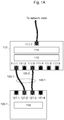
- Figs. 1A-1D illustrate an example system 100 in various example arrangements.
- the example system 100 illustrated in Figs. 1A-1D includes an example network device 110 and example peer devices 120.
- the network device 110 may serve as a network node to connect the peer devices 120 to other network nodes (not illustrated), which may be nodes in the same network as the network device 110 or in an external network.
- the network device 110 may be, for example, a switch, a PSE, a router, or the like.
- the network device 110 includes physical communication interfaces 111 for communicably connecting the network device 110 to other devices, such as the peer devices 120 and the network node (not illustrated).
- the numbers and arrangements of physical communications interfaces 111 illustrated in Figs. 1A-1 D are merely examples, and the network device 110 is not limited to these examples. In particular, the network device 110 can have any number of physical communication interfaces 111 that is equal to or greater than two.
- certain physical communication interfaces 111 may be configured specifically for connecting to the network node (uplink ports), while other physical communication interfaces 111 may be configured specifically for connecting to peer devices 120 (downlink ports). In other example configurations, any of the physical communication interfaces 111 may be used for connecting to either the network node or the peer devices 120.
- Figs. 1A-1 D illustrate a physical communication interface 111-7 that is connected to the network node, but this is merely one example and any number of communications interfaces 111 may be connected to the network node.
- the network device 110 may also include an interface controller 115 that is to configure parameters of the physical communication interfaces 111.
- the interface controller 115 may be hardware and/or machine-readable instructions that are configured to perform certain operations described herein.
- the interface controller 115 may be realized by processing circuitry 151 (discussed further below) executing machine-readable instructions.
- the interface controller 115 may also include, for example, an application-specific integrated circuit (ASIC), a field-programmable gate array (FPGA), an application-specific instruction set processor (ASIP), or the like, configured to perform certain operations described herein.
- ASIC application-specific integrated circuit
- FPGA field-programmable gate array
- ASIP application-specific instruction set processor
- the network device 110 may also include a link aggregator 116 that is to aggregate links.
- the link aggregator 116 may be hardware and/or machine-readable instructions that are configured to perform certain operations described herein.
- the interface controller 115 may be realized by processing circuitry 151 (discussed further below) executing machine-readable instructions.
- the link aggregator 116 may also include, for example, an application-specific integrated circuit (ASIC), a field-programmable gate array (FPGA), an application-specific instruction set processor (ASIP), or the like, configured to perform certain operations described herein.
- the link aggregator 116 may be hardware and/or machine-readable instructions that implement a link aggregation protocol, such as the Link Aggregation Control Protocol (LACP), IEEE 802.1AX-2008.
- LACP Link Aggregation Control Protocol
- IEEE 802.1AX-2008 IEEE 802.1AX-2008.
- the peer devices 120 may be any device that can be communicably connected to the network device 110 via the physical communication interfaces 111.
- the peer devices 120 may be a Wi-Fi access point, a network switch, a personal computer, and so on.
- the peer devices 120 include physical communication interfaces 121 for communicably connecting the peer devices 120 to other devices.
- the numbers and arrangements of physical communication interfaces 121 shown in Figs. 1A-1D are merely examples, and any number or arrangement of physical communication interfaces 121 can be included in the peer devices 120.
- the peer devices 120 may also include a link aggregator 126 for aggregating links. If the link aggregator 126 of the peer device 120 implements a link aggregation protocol that is compatible with that used by the network device 110, then the network device 110 and the peer device 120 may aggregate links between them.
- the network device 110 and the peer devices 121 may be communicably connected to each other by connecting a connector 130 between a physical communication interface 111 of the network device 110 and a physical communication interface 121 of the respective peer device 120.
- the connectors 130 may be any type of physical media that is capable of transmitting signals between the physical communication interfaces 111 and 121, such as, for example, Ethernet cables, optical fiber cables, universal serial bus (USB) cables, IEEE 1394 (Firewire) cables, and so on.
- a link aggregation group (LAG) 140 is a single logical communication link that is formed by aggregating multiple such physical communication links.
- the network device 110 may detect whenever more than one communication links are established with the same peer device 120, and in response to detecting this, may automatically configure the links that are connected to the same peer device 120 for aggregation into the same LAG 140.
- the interface controller 115 may automatically configure the more than one physical communication interfaces 111 in such a manner that the link aggregator 116 will automatically begin negotiating with the peer device 120 to establish an LAG 140 that includes the links associated with the more than one physical communication interfaces 111.
- "begin negotiating with the peer device” means at least sending a message to the peer device 120 that is related to establishing the LAG 140. Sending an LACP packet to the peer device 120 is an example of beginning negotiating with the peer device 120. The peer device 120 may continue the negotiations by responding to the message (for example, sending back an LACP packet), and the LAG 140 may ultimately be established at the conclusion of the negotiations.
- Whether or not the LAG 140 is ultimately established as a result of the negotiations may depend on the configuration of the peer device 120. For example, formation of the LAG 140 may depend on whether or not the network device 111 and the peer device 120 are using the same (or compatible) protocols for link aggregation. As another example, even if the protocols being used are compatible, formation of the LAG 140 may depend on whether or not the peer device 120 has link aggregation enabled for the appropriate physical communication interfaces 121.
- the interface controller 115 may specify which physical communication interfaces 111 should be included in a particular LAG 140 by configuring certain parameters of the physical communication interfaces 111.
- the physical communication interfaces 111 may have a particular configuration parameter associated therewith that identifies which LAG 140 (if any) the physical communications interfaces 111 are assigned to, and the link aggregator 116 may determine which physical communication interfaces 111 to include in which LAGs 140 based on the values of this parameter.
- the configuration parameter may be an LACP key (also referred to as a "group identifier”, “group ID”, “LAG identifier”, or “LAG ID”), and physical communication interfaces 111 that have the same value for their group ID parameter are included by the link aggregator 116 in the same LAG 140 as one another.
- LACP key also referred to as a "group identifier”, “group ID”, “LAG identifier”, or "LAG ID”
- Non-aggregated ports Physical communication interfaces 111 that are not to be included in any LAG 140 (hereinafter “non-aggregated ports”) may be identified by, for example, setting a flag that indicates a non-aggregated port, leaving configuration parameters related to link aggregation blank, setting configuration parameters related to link aggregation to values that indicate an non-aggregated port, or by any other technique.
- the physical communication interfaces 111 that are to be included in a particular LAG 140 may also have certain other configuration parameters related to link aggregation that should be set before being included in the LAG 140.
- additional configuration parameters may include an LACP mode (e.g., active or passive), a priority, a timeout (e.g., short or long), an independent state parameter, and so on.
- the interface controller 115 automatically configures these parameters on those physical communication interfaces 111 that are to be included in a LAG 140.
- corresponding ones of their link aggregation parameters may be set to the same respective values.
- the interface controller 115 may make the aforementioned configurations by determining link aggregation profiles and applying a profile to the physical communication interface 111.
- a link aggregation profile may include a particular combination of values that are to be set for various configuration parameters.
- a conceptual example of a configuration profile is shown in Fig. 3 .
- Applying a link aggregation profile to a physical communication interface 111 means configuring parameters of the physical communication interface 111 based on the values assigned to these parameters in the profile.
- the physical communication interfaces 111 When the same link aggregation profile is applied to two physical communication interfaces 111, the physical communication interfaces 111 will be identically configured with respect to the relevant link aggregation parameters (including their group ID), and thus the link aggregator 116 will automatically attempt to include the two physical communication interfaces 111 in the same LAG 140 as one another.
- the interface controller 115 may indicate to the link aggregator 116 that certain physical communications interfaces 111 should be assigned to the same LAG 140 as one another by applying the same link aggregation profile to the selected physical communications interfaces 111.
- the configuration of the physical communication interfaces 111 to be in the same LAG 140 is done in response to determining that the physical communication interfaces 111 are connected to the same peer device 120 as one another. This determination may be done by detecting the identity of the peer device 120 that is connected to each physical communication interface 111, and comparing these identifies to each other.
- the interface controller 115 may detect the identity of a peer device 120 that is connected to a given physical communications interface 111 by any available discovery technique.
- the Link Layer Discovery Protocol (LLDP) (also referred to as Station and Media Access Control Connectivity Discovery), IEEE 802.1AB, may be used to detect the identities of peer devices 120 connected to the physical communications interfaces 111.
- Other examples of discovery protocols include Cisco Discovery Protocol (CDP), Extreme Discovery Protocol, Foundry Discovery Protocol (FDP), Nortel Discovery Protocol (also known as SONMP), and Microsoft's Link Layer Topology Discovery (LLTD).
- the network device 110 may automatically configure the two physical communication interfaces 111 and begin negotiations in the manner described herein regardless of how the peer device 120 is configured in relation to link aggregation.
- the interface controller 115 may automatically reconfigure the relevant physical communication interfaces 111 to be non-aggregated ports, for example, by returning them to a configuration they had prior to being configured to join a LAG 140.
- the configuration of the physical communication interfaces 111 may be left unchanged, which will result in the physical communication interfaces 111 automatically being put into an independent state in which they continue to carry traffic like a non-aggregated port but also continue to periodically send LACP packets.
- the interface controller 115 may automatically configure the physical communications interfaces 111-1 and 111-3 to be in the same LAG 140 as one another (i.e., LAG 140-1).
- the interface controller 115 may automatically configure the physical communications interfaces 111-1 and 111-3 based on the same link aggregation profile, which will indicate to the link aggregator 116 that they are to be included in the same LAG 140. Once the physical communications interfaces 111-1 and 111-3 are so configured, the link aggregator 116 may automatically begin negotiating with the peer device 120-1 for establishment of the LAG 140-1.
- a user does not need to identify which physical communications interfaces 111 should be aggregated into an LAG 140 or manually configure the physical communications interfaces 111 to enable them to be included in the LAG 140. Instead, a user can simply plug connectors 130 into any of the physical communications interfaces 111, and the network device 110 will automatically configure the appropriate physical communications interfaces 111 such that an LAG 140 can be formed.
- the interface controller 115 may also detect changes in connections between the network device 110 and peer devices 120 after an LAG 140 has been formed, and may automatically adjust the LAG 140 based on these changes in connections (by changing the configurations of the physical communication interfaces 111).
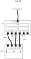
- FIG. 1B corresponds to the arrangement shown inFig. 1A, with the addition of a new link between the network device 110 and the peer device 120-1.
- a new link with the peer device 120-1 is formed when the connector 130-3 is newly connected to the physical communications interfaces 111-4 and 121-4.
- the interface controller 115 may automatically configure the physical communications interface 111-4 to be added to the LAG 140-1, which already includes the other two links to the peer device 120-1. For example, the interface controller 115 may configure the physical communications interface 111-4 based on the same link aggregation profile that was previously used to configure physical communications interfaces 111-1 and 111-3, which will signal to the link aggregator 116 that the physical communications interface 111-4 is to join LAG 140-1.
- the interface controller 115 may automatically configure the physical communications interface 111-4 to be removed from the LAG 140-1.
- parameters of the physical communications interface 111-4 may automatically be reset to the values they had prior to being configured for including in the LAG 140-1, the parameters of the physical communications interface 111-4 may be set to default values for a non-aggregated port, or a profile for non-aggregated ports may be applied to the physical communications interface 111-4.
- the physical communications interface 111-2 may automatically be configured so as to be added to the LAG 140-1.
- the interface controller 115 may automatically configure the physical communications interface 111-2 based on the same link aggregation profile that was used to configure physical communications interfaces 111-1 and 111-3, which will signal to the link aggregator 116 that the physical communications interface 111-2 is to join LAG 140-1.
- the LAG 140-1 may continue to operate as an aggregate link, albeit with only two links instead of the previous three links.
- a user can add new links between the network device 110 and the peer device 120 or move links between different ports, and the LAG 140 will automatically be updated to include the new links or the new configuration of links.
- the user does not need to configure any physical communication interfaces 111 or take any other special steps besides plugging in a new connector 130, since the interface controller 115 will automatically detect the new link and appropriately configure the physical communication interfaces 111.
- the interface controller 115 may also detect when the network device 110 is connected to multiple peer devices 120, and may automatically create different LAGs 140 for the different peer devices 120 (by changing the configurations of the physical communication interfaces 111). In particular, whenever two or more peer devices 120 are connected to the network device 110, the network device 110 may establish different LAGs 140 for each one of the peer devices 120 that has more than one link with the network device 110. For any peer devices 120 that have only one link to the network device 110, their link is not included in any LAG 140.
- links associated with different peer devices 120 are not aggregated into the same LAG 140 as one another, and all links to the same peer device 120 are aggregated into the same LAG 140 as one another (unless there is only one link for that peer device 120, in which case it remains a non-aggregated link).
- the connectors 130-4 and 130-5 have been connected between the physical communications interfaces 111-5 and 111-6 and the physical communications interfaces 121-6 and 121-7 of the peer device 120-2.
- the connector 130-4 was connected before the connector 130-5.
- the interface controller 115 maintains the physical communications interface 111-5 in a non-aggregated configuration.
- the physical communications interface 111-5 is not added to the existing LAG 140-1 because the physical communications interface 111-5 is connected to peer device 120-2, while the links of LAG 140-1 are connected the peer device 120-1. A new LAG 140 is not established for the peer device 120-2 at this time, since there is still only one link to the peer device 120-2.
- the interface controller 115 In response to detecting that the physical communications interface 111-6 is newly connected to the same peer device as the physical communication interfaces 111-5 (i.e., peer device 120-2), the interface controller 115 automatically configures both the physical communications interfaces 111-5 and 111-6 to be included in a new LAG 140-2.
- the interface controller 115 may automatically configure the physical communications interfaces 111-5 and 111-6 based on the same link aggregation profile as one another, which is a different link aggregation profile from the one that was used to configure physical communications interfaces 111-1, 111-3, and 111-4. This will inform the link aggregator 116 that the new LAG 140-2, which includes the physical communications interfaces 111-5 and 111-6, should be established.
- a user can connect multiple peer devices 120 to the network device 110, and LAGs 140 will automatically be generated for the peer devices 120 without the user having to configure any of the physical communications interfaces 111.
- the user When connecting the multiple peer devices 120 for the first time or when adding new links or moving links between ports, the user will not have to remember which LAG 140 is associated with which peer device 120 or which physical communication interfaces 111 are included in which LAGs 140, much less go through the process of manually configuring these physical communication interfaces 111. Instead the user can simply plug new connectors 130 into any available physical communication interfaces 111 or move connectors 130 between any physical communication interfaces 111, since the interface controller 115 will automatically sort out which physical communication interfaces 111 should be included in which LAGs 140 and perform the appropriate configurations.
- the interface controller 115 may also detect when links between the network device 110 and a peer device 120 are removed, and may automatically update any existing LAGs 140 accordingly. In particular, if a physical communication interface 111 that is included in an existing LAG 140 is disconnected, then the physical communication interface 111 may be configured to be removed from the LAG 140. If the LAG 140 still has two or more links despite the loss of the disconnected physical communication interface 111, the LAG 140 may be kept running. If, on the other hand, the LAG 140 has only one remaining link after the physical communication interface 111 is disconnected, then the LAG 140 may automatically be torn down by configuring the physical communication interface 111 of the remaining link to be removed from the LAG 140.
- the example network device 110 may include a processing block 150 and the physical communications interfaces 111.
- the processing block 150 may include, for example, processing circuitry 151 and a memory 152.
- the processing circuitry151 may be any circuitry capable of executing machine-readable instructions, such as a central processing unit (CPU), a microprocessor, a microcontroller device, a digital signal processor (DSP), etc.
- the memory 152 may be any non-transitory machine readable medium, which may include volatile storage media (e.g., DRAM, SRAM, etc.) and/or non-volatile storage media (e.g., PROM, EPROM, EEPROM, NVRAM, hard drives, optical disks, etc.).
- the memory 152 may store machine-readable instructions that, when executed by the processing circuitry151, cause the network device 110 to perform the operations described herein, such as the operations described in Figs. 3-6 .
- the memory 153 may include interface controller instructions 153, which may include instructions to perform any of the operations described herein in relation to the interface controller 115.
- the memory 152 may be one example of the non-transitory computer readable medium 1000 illustrated in Fig. 7 , in which case the interface controller instructions 153 would correspond to the interface controller instructions 1010.
- the processing block 150 may also include, in addition to or in lieu of the processing circuitry 151 and memory 152, an application-specific integrated circuit (ASIC), a field-programmable gate array (FPGA), an application-specific instruction set processor (ASIP), or the like, configured to perform certain operations described herein.
- ASIC application-specific integrated circuit
- FPGA field-programmable gate array
- ASIP application-specific instruction set processor
- the interface controller 115 and/or the link aggregator 116 may be instantiated by the processing block 150.
- the interface controller 115 and/or the link aggregator 116 may be formed by the processing circuitry151 executing instructions stored in the memory 152, which may include the interface controller instructions 153.
- Only one processing circuitry151 and one memory 152 are illustrated, multiple instances of these may be included in the network device 110.
- Fig. 3 illustrates an example link aggregation profile.
- the link aggregation profile may include a collection of values, one for each of a collection of configuration parameters.
- the configuration parameters may include parameters that the link aggregator 116 uses to be configured in order to establish an LAG 140.
- the configuration parameters may also include additional parameters that are related to link aggregation.
- the configuration parameters include at least a parameter for identifying the LAG 140 to which the physical communications interface 111 is to be assigned.
- the parameter for identifying the LAG 140 may be an LACP key (also referred to herein as a group ID).
- Other example parameters that may be included in the link aggregation profile may include LACP mode (active vs passive), LACP System Priority, timeout (long vs short), and independent state (enabled vs disabled).
- Fig. 4 illustrates an example process for configuring physical communication interfaces 111 for link aggregation.
- the example process may be performed, for example, by the processing block 150.
- the memory 152 may store machine-readable instructions that, when executed by the processing circuitry151, cause the operations of the example process to be performed.
- port_A and port_B are automatically configured to be included in the same LAG 140 as one another.
- the operation of block 402 may include, for example, automatically determining a link aggregation group profile for port_A and port_B, and then automatically applying the profile to port_A and port_B. Determining the link aggregation profile for port_A and port_B may include selecting a profile from among a set of pre-established profiles and assigning it to port_A and port_B. Determining the link aggregation profile for port_A and port_B may also include generating a new profile for port_A and port_B. Applying the profile to port_A and port_B may include configuring certain parameters of port_A and port_B based on the values set in the profile for those parameters.
- references herein and in the appended claims to an operation being performed "automatically” in response to some condition mean that further user action after fulfillment of the condition is not required for the operation to be performed.
- User actions that occur prior to the recited condition being fulfilled do not keep the action from being automatic, even if the user action is a necessary antecedent for the operation.
- the fact that a user may plug a connector 130 into a physical communications interface 111 does not keep the subsequent configuration of the ports from being automatic, because the user action occurred prior to the recited condition (the detection of block 401).
- a user may need to first globally enable link aggregation (a user action) before the operations described herein may be performed, but this does not prevent the subsequent configuration of the ports from being automatic, because the user action occurred prior to the recited condition (the detection of block 401).
- negotiations with the peer device for establishing a LAG 140 that includes the links associated with port_A and port_B are automatically begun. This may include, for example, sending a message to the peer device related to establishing the LAG 140.
- block 403 may include sending LACP packets to the peer device via port_A and port_B whose content is based on the configuration of the ports, which will indicate to the peer device that the network device 110 desires to aggregate the links into an LAG 140. If the peer device is able and willing to participate in the aggregation, the peer device may send LACP packets back to the network device 110 via its interfaces that are connected to port_A and port_B, which may enable the LAG 140 to be established.
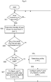
- Fig. 5 illustrates another example process for configuring physical communication interfaces 111 for link aggregation.
- the example process may be performed, for example, by the processing block 150.
- the memory 152 may store machine-readable instructions that, when executed by the processing circuitry151, cause the operations of the example process to be performed.
- the physical communication interface 111 for which a new connection was detected is referred to as port P j in Fig. 5 .
- the identity of the peer device 120 that port P j is connected to is determined.
- the peer device 120 that port P j is connected to is referred to as D i in Fig. 4 .
- LLDP may be used to identify the peer device D i .
- block 503 NO
- no further actions are taken with regard to the port P j at this time, and the process returns to block 501 to continue monitoring for new connections.
- block 503 is answered NO, this corresponds to the case in which the port P j was the first port connected to the peer device D i . Since there is only one link with the peer device D i in this case, no LAG 140 is to be formed that includes the port P j .
- block 503 YES
- the process proceeds to block 504.
- block 503 is answered YES, this corresponds to the case in which there are multiple links with the peer device D i .
- the process proceeds to configure the port P j for aggregation into a LAG 140 (whether that be joining an existing LAG 140, or creating a new LAG 140).
- block 504 NO
- the process proceeds to block 505.
- block 504 is answered NO, this generally corresponds to the case in which there is only one port P k that was already connected to the peer device D i when the port P j was newly connected. This is so because generally an LAG 140 would already exist if more than one port were already connected to the peer device D i prior to the new connection to port P j .
- a link aggregation profile [LAG] i is determined for the ports ⁇ P k ⁇ and P j that are connected to the device D i .
- the link aggregation profile [LAG] i that was determined in block 505 is applied to the ports P j and P k .
- the ports P j and P k are configured based on the profile [LAG] i .
- the reason that the port P k is configured in addition to the port P j is because the port P k was not previously included in an LAG 140 (recall that block 506 is only reached if the port P k was not previously included in an LAG 140).
- the port P j has the same profile applied to it that was previously applied to the ports ⁇ P k ⁇ . Recall that if block 507 is reached, then the ports ⁇ P k ⁇ were already aggregated into an LAG 140, and hence they would have already been configured based on a particular profile. Thus, if the profile that was used to configure the ports ⁇ P k ⁇ is represented as [LAG] i , then the port P j is configured based on the profile [LAG] i . The reason that the ports ⁇ P k ⁇ do not necessarily need to be configured in block 507 is that they have already been configured to be in the LAG 140. If for some reason one of the ports ⁇ P k ⁇ is not already included the LAG 140, then it too may be configured based on the profile [LAG] i .
- Fig. 6 illustrates an example process for handling physical communication interfaces 111 that are part of an LAG 140 being disconnected.
- the example process may be performed, for example, by the processing block 150.
- the memory 152 may store machine-readable instructions that, when executed by the processing circuitry151, cause the operations of the example process to be performed.
- the physical communication interface 111 that was disconnected from a peer device 120 is referred to as port P j in Fig. 5 .
- both the port P k and the port P j are configured for removal from the LAG 140.
- the process proceeds to block 604 in which the port P k is configured for removal from the LAG 140, and then to block 605 in which the port P j is configured for removal from the LAG 140.
- the port P j is removed from the LAG 140 because it is no longer connected to the peer device 120 that is associated with the LAG 140.
- the port P k is also removed from the LAG 140 because it is now the only physical communications interface 111 that is still connected to the peer device 120 associated with the LAG 140, and hence the LAG 140 needs to be torn down.
- port P j is configured for removal from the LAG 140.
- the other ports in the LAG 140 do not need to be configured for removal from the LAG 140, because there are still at least two ports connected to the peer device 120 associated with the LAG 140.
- the configuring of the various physical communication interfaces 111 for removal from a LAG 140 may include, for example, returning the link aggregation parameters of the physical communication interfaces 111 to the values they had prior to being configured to join the LAG 140, configuring the physical communications interfaces 111 based on default values for non-aggregated ports, or the like.
- Fig. 7 illustrates an example non-transitory computer readable medium 1000.
- the non-transitory computer readable medium 1000 may include volatile storage media (e.g., DRAM, SRAM, etc.) and/or non-volatile storage media (e.g., PROM, EPROM, EEPROM, NVRAM, hard drives, optical disks, etc.).
- the non-transitory computer readable medium 1000 may store machine-readable instructions that are configured to, when executed by processing circuitry (such as the processing circuitry 151) of a network device (such as the network device 110), cause the network device to perform operations described above, such as the operations described in Figs. 3-6 .
- the memory 152 may be one example of the non-transitory computer readable medium 1000.
- the non-transitory computer readable medium 1000 may include interface controller instructions 1010.
- the interface controller instructions 1010 may be to implement certain operations described above as being performed by the interface controller 115.
- the interface controller 115 described above may be instantiated by processing circuitry (such as the processing circuitry 151) executing the interface controller instructions 1010.
- the interface controller instructions 1010 may include, for example, instructions to detect connections 1011 and instructions to configure interfaces 1012.
- the interface controller instructions 1010 may include additional instructions (not illustrated) to implement any or all of the operations described in Figs. 3-6 .
- the instructions to detect connections 1011 may include, for example, instructions to monitor physical communications interfaces (such as the physical communications interfaces 111) of a communication device (such as the network device 110) for connections to peer devices (such as the peer devices 120).
- the instructions to configure interfaces 1012 may include, for example, instructions to, in response to detecting that at least two of the physical communications interfaces are connected to a same peer device as one another, automatically configure the at least two of the physical communications interfaces for aggregation into a same link aggregation group as one another.
- the discussion above focuses on aggregation of links between the peer device 120 and the network device 110, the same processes described above could be used to configure links with the other network node.
- the other network node may simply be considered as another peer device 120 for purposes of the processes described above.
Landscapes
- Engineering & Computer Science (AREA)
- Computer Networks & Wireless Communication (AREA)
- Signal Processing (AREA)
- Automation & Control Theory (AREA)
- Data Exchanges In Wide-Area Networks (AREA)
- Mobile Radio Communication Systems (AREA)
Applications Claiming Priority (1)
| Application Number | Priority Date | Filing Date | Title |
|---|---|---|---|
| IN201641008663 | 2016-03-11 |
Publications (2)
| Publication Number | Publication Date |
|---|---|
| EP3217607A1 true EP3217607A1 (fr) | 2017-09-13 |
| EP3217607B1 EP3217607B1 (fr) | 2019-12-18 |
Family
ID=58397996
Family Applications (1)
| Application Number | Title | Priority Date | Filing Date |
|---|---|---|---|
| EP17160029.9A Active EP3217607B1 (fr) | 2016-03-11 | 2017-03-09 | Configuration d'interfaces de communication pour l'agrégation de liens |
Country Status (2)
| Country | Link |
|---|---|
| US (1) | US10374895B2 (fr) |
| EP (1) | EP3217607B1 (fr) |
Cited By (3)
| Publication number | Priority date | Publication date | Assignee | Title |
|---|---|---|---|---|
| CN109450788A (zh) * | 2018-10-31 | 2019-03-08 | 新华三云计算技术有限公司 | 虚拟服务器的初始化方法、装置以及电子设备 |
| CN110611715A (zh) * | 2019-09-23 | 2019-12-24 | 国云科技股份有限公司 | 一种服务链路集合云监控信息的系统和方法 |
| US10862794B2 (en) | 2019-01-31 | 2020-12-08 | Dell Products L.P. | Automated link aggregation group configuration system |
Families Citing this family (8)
| Publication number | Priority date | Publication date | Assignee | Title |
|---|---|---|---|---|
| FR3072527B1 (fr) * | 2017-10-17 | 2019-10-18 | Sagemcom Broadband Sas | Gestion de la connexion avec d'autres passerelles residentielles d'une passerelle residentielle mettant en œuvre l'agregation de liens |
| US11190440B2 (en) * | 2018-01-19 | 2021-11-30 | Vmware, Inc. | Methods and apparatus to configure and manage network resources for use in network-based computing |
| US11102142B2 (en) | 2018-01-24 | 2021-08-24 | Vmware, Inc. | Methods and apparatus to perform dynamic load balancing for a multi-fabric environment in network-based computing |
| US10616319B2 (en) | 2018-02-06 | 2020-04-07 | Vmware, Inc. | Methods and apparatus to allocate temporary protocol ports to control network load balancing |
| CN111866195B (zh) * | 2019-04-26 | 2022-05-24 | 华为技术有限公司 | 一种端口协商方法及装置 |
| CN111555972A (zh) * | 2020-04-10 | 2020-08-18 | 深圳震有科技股份有限公司 | 一种聚合链路的汇聚方法、系统及存储介质 |
| CN112953824B (zh) * | 2021-01-28 | 2022-03-29 | 新华三信息安全技术有限公司 | 一种链路聚合的配置方法及装置 |
| CN115037604A (zh) * | 2022-05-25 | 2022-09-09 | 新华三技术有限公司 | 一种接口配置方法及装置 |
Citations (7)
| Publication number | Priority date | Publication date | Assignee | Title |
|---|---|---|---|---|
| EP0876076A2 (fr) * | 1997-04-30 | 1998-11-04 | Nec Corporation | Agrégation de la topologie utilisant un paramètre obtenu par négotiation entre noeuds |
| US20080112312A1 (en) * | 2006-11-10 | 2008-05-15 | Christian Hermsmeyer | Preemptive transmission protection scheme for data services with high resilience demand |
| US20090228626A1 (en) * | 2008-03-07 | 2009-09-10 | Via Technologies, Inc. | Host modules, electronic devices, electronic systems and data transmission method thereof |
| EP2242219A1 (fr) * | 2002-10-07 | 2010-10-20 | Nippon Telegraph And Telephone Corporation | Noeud de réseau en couches |
| US7869432B1 (en) * | 2007-06-29 | 2011-01-11 | Force 10 Networks, Inc | Peer-to-peer link aggregation across a service provider network |
| US20130315255A1 (en) * | 2009-08-05 | 2013-11-28 | Cisco Technology, Inc. | Signaling of attachment circuit status and automatic discovery of inter-chassis communication peers |
| US20140372576A1 (en) * | 2013-06-12 | 2014-12-18 | Alcatel-Lucent Usa Inc. | System, method, and apparatus for network fabric configuration in data communication networks |
Family Cites Families (17)
| Publication number | Priority date | Publication date | Assignee | Title |
|---|---|---|---|---|
| WO2004102894A1 (fr) | 2003-05-15 | 2004-11-25 | 3Com Corporation | Systeme et procede de gestion de la fourniture d'energie sur des lignes de donnees |
| US20060210057A1 (en) | 2005-01-25 | 2006-09-21 | Linear Technology Corporation | Supplying power over four pairs of conductors in communication cable |
| US8037324B2 (en) | 2007-03-20 | 2011-10-11 | Broadcom Corporation | Power over ethernet connector with integrated power source equipment (PSE) controller supporting high power applications |
| US8793511B1 (en) | 2009-03-23 | 2014-07-29 | Marvell International Ltd. | Power management for power over ethernet (PoE) system based on network communication transmission rate |
| US8780911B2 (en) * | 2009-10-08 | 2014-07-15 | Force10 Networks, Inc. | Link aggregation based on port and protocol combination |
| US8224401B1 (en) | 2010-01-19 | 2012-07-17 | Adtran, Inc. | System and method for controlling a powered device that draws power from a communications network in response to user detection |
| JP5513342B2 (ja) * | 2010-02-26 | 2014-06-04 | アラクサラネットワークス株式会社 | パケット中継装置 |
| CN104253764B (zh) * | 2013-06-28 | 2017-05-17 | 新华三技术有限公司 | 一种链路聚合的方法和设备 |
| CN104518936B (zh) * | 2013-09-27 | 2019-02-19 | 新华三技术有限公司 | 链路动态聚合方法和装置 |
| US9690343B2 (en) | 2014-02-11 | 2017-06-27 | Dell Products L.P. | Power distribution system |
| US9288139B2 (en) | 2014-04-02 | 2016-03-15 | Qualcomm Incorporated | Methods for selection of link aggregation capable access points |
| US9792106B1 (en) * | 2014-08-04 | 2017-10-17 | Cisco Technology, Inc. | Technique for fast network device configuration upgrade and reload |
| US9635148B2 (en) * | 2014-10-31 | 2017-04-25 | Aruba Networks, Inc. | Partitioning data sets for transmission on multiple physical links |
| US9912580B2 (en) * | 2015-04-08 | 2018-03-06 | Dell Products Lp | Link fallback |
| CN106330780B (zh) * | 2015-06-24 | 2019-08-20 | 联想企业解决方案(新加坡)有限公司 | 用于构成聚合链路的交换机、设备和方法 |
| WO2017019108A1 (fr) * | 2015-07-30 | 2017-02-02 | Hewlett Packard Enterprise Development Lp | Mise à jour de micrologiciel d'un dispositif d'interconnexion |
| US10248447B2 (en) * | 2015-11-25 | 2019-04-02 | Red Hat, Inc. | Providing link aggregation and high availability through network virtualization layer |
-
2017
- 2017-02-08 US US15/427,118 patent/US10374895B2/en active Active
- 2017-03-09 EP EP17160029.9A patent/EP3217607B1/fr active Active
Patent Citations (7)
| Publication number | Priority date | Publication date | Assignee | Title |
|---|---|---|---|---|
| EP0876076A2 (fr) * | 1997-04-30 | 1998-11-04 | Nec Corporation | Agrégation de la topologie utilisant un paramètre obtenu par négotiation entre noeuds |
| EP2242219A1 (fr) * | 2002-10-07 | 2010-10-20 | Nippon Telegraph And Telephone Corporation | Noeud de réseau en couches |
| US20080112312A1 (en) * | 2006-11-10 | 2008-05-15 | Christian Hermsmeyer | Preemptive transmission protection scheme for data services with high resilience demand |
| US7869432B1 (en) * | 2007-06-29 | 2011-01-11 | Force 10 Networks, Inc | Peer-to-peer link aggregation across a service provider network |
| US20090228626A1 (en) * | 2008-03-07 | 2009-09-10 | Via Technologies, Inc. | Host modules, electronic devices, electronic systems and data transmission method thereof |
| US20130315255A1 (en) * | 2009-08-05 | 2013-11-28 | Cisco Technology, Inc. | Signaling of attachment circuit status and automatic discovery of inter-chassis communication peers |
| US20140372576A1 (en) * | 2013-06-12 | 2014-12-18 | Alcatel-Lucent Usa Inc. | System, method, and apparatus for network fabric configuration in data communication networks |
Cited By (6)
| Publication number | Priority date | Publication date | Assignee | Title |
|---|---|---|---|---|
| CN109450788A (zh) * | 2018-10-31 | 2019-03-08 | 新华三云计算技术有限公司 | 虚拟服务器的初始化方法、装置以及电子设备 |
| CN109450788B (zh) * | 2018-10-31 | 2021-08-06 | 新华三云计算技术有限公司 | 虚拟服务器的初始化方法、装置以及电子设备 |
| US10862794B2 (en) | 2019-01-31 | 2020-12-08 | Dell Products L.P. | Automated link aggregation group configuration system |
| US11601360B2 (en) | 2019-01-31 | 2023-03-07 | Dell Products L.P. | Automated link aggregation group configuration system |
| CN110611715A (zh) * | 2019-09-23 | 2019-12-24 | 国云科技股份有限公司 | 一种服务链路集合云监控信息的系统和方法 |
| CN110611715B (zh) * | 2019-09-23 | 2023-11-28 | 国云科技股份有限公司 | 一种服务链路集合云监控信息的系统和方法 |
Also Published As
| Publication number | Publication date |
|---|---|
| US10374895B2 (en) | 2019-08-06 |
| US20170264490A1 (en) | 2017-09-14 |
| EP3217607B1 (fr) | 2019-12-18 |
Similar Documents
| Publication | Publication Date | Title |
|---|---|---|
| EP3217607B1 (fr) | Configuration d'interfaces de communication pour l'agrégation de liens | |
| US7881230B2 (en) | Facilitating self configuring link aggregation using link aggregation control protocol | |
| KR101869902B1 (ko) | Sdn 제어기, 데이터 센터 시스템, 및 라우팅 연결 방법 | |
| EP1982447B1 (fr) | Systeme et procede de detection et de restauration a partir de pannes de commutateurs virtuels | |
| US8005013B2 (en) | Managing connectivity in a virtual network | |
| US8400912B2 (en) | Activating a tunnel upon receiving a control packet | |
| CN1947024B (zh) | 用于检测链路故障的系统和方法 | |
| EP2933977B1 (fr) | Procédé, élément de réseau et réseau pour vérification d'intégrité des trames de connectivité en direct | |
| US20140372576A1 (en) | System, method, and apparatus for network fabric configuration in data communication networks | |
| CN105871674B (zh) | 环保护链路故障保护方法、设备及系统 | |
| US20150271103A1 (en) | Distributed hot standby links for vlag | |
| US20140369230A1 (en) | Virtual Chassis Topology Management | |
| CN104125088A (zh) | Drni中同一端内系统之间交互信息的方法和系统 | |
| WO2014040466A1 (fr) | Procédé et dispositif de commande d'ap | |
| CN102624745B (zh) | 一种路径计算单元通信协议会话建立方法及装置 | |
| US8279752B1 (en) | Activating tunnels using control packets | |
| US10084656B2 (en) | TRILL network establishing method, node, and system | |
| US20040105455A1 (en) | Automatic edge port and one way connectivity detection with rapid reconfiguration for shared media in spanning tree configured bridged Local Area Networks | |
| WO2017101762A1 (fr) | Procédé de traitement du mode de négociation et dispositif de réseau intelligent | |
| CN111585791B (zh) | 一种数据同步配置方法、系统及存储介质 | |
| EP2858302B1 (fr) | Procédé de vérification de connectivité sur une liaison de flux de service, appareil connexe, et système | |
| CN104125079A (zh) | 一种确定双机热备份配置信息的方法及装置 | |
| CN112995002B (zh) | 一种交换机环网的设计方法、交换机及存储介质 | |
| CN108667640A (zh) | 通信方法及设备、网络接入系统 | |
| CN103401702A (zh) | 一种基于全分布式模型的tcp连接管理方法及设备 |
Legal Events
| Date | Code | Title | Description |
|---|---|---|---|
| PUAI | Public reference made under article 153(3) epc to a published international application that has entered the european phase |
Free format text: ORIGINAL CODE: 0009012 |
|
| STAA | Information on the status of an ep patent application or granted ep patent |
Free format text: STATUS: THE APPLICATION HAS BEEN PUBLISHED |
|
| AK | Designated contracting states |
Kind code of ref document: A1 Designated state(s): AL AT BE BG CH CY CZ DE DK EE ES FI FR GB GR HR HU IE IS IT LI LT LU LV MC MK MT NL NO PL PT RO RS SE SI SK SM TR |
|
| AX | Request for extension of the european patent |
Extension state: BA ME |
|
| RAP1 | Party data changed (applicant data changed or rights of an application transferred) |
Owner name: ARUBA NETWORKS, INC. |
|
| STAA | Information on the status of an ep patent application or granted ep patent |
Free format text: STATUS: REQUEST FOR EXAMINATION WAS MADE |
|
| 17P | Request for examination filed |
Effective date: 20180312 |
|
| RBV | Designated contracting states (corrected) |
Designated state(s): AL AT BE BG CH CY CZ DE DK EE ES FI FR GB GR HR HU IE IS IT LI LT LU LV MC MK MT NL NO PL PT RO RS SE SI SK SM TR |
|
| STAA | Information on the status of an ep patent application or granted ep patent |
Free format text: STATUS: EXAMINATION IS IN PROGRESS |
|
| 17Q | First examination report despatched |
Effective date: 20181108 |
|
| RAP1 | Party data changed (applicant data changed or rights of an application transferred) |
Owner name: HEWLETT PACKARD ENTERPRISE DEVELOPMENT LP |
|
| GRAP | Despatch of communication of intention to grant a patent |
Free format text: ORIGINAL CODE: EPIDOSNIGR1 |
|
| STAA | Information on the status of an ep patent application or granted ep patent |
Free format text: STATUS: GRANT OF PATENT IS INTENDED |
|
| RIC1 | Information provided on ipc code assigned before grant |
Ipc: H04L 12/709 20130101AFI20190709BHEP Ipc: H04L 12/24 20060101ALI20190709BHEP |
|
| INTG | Intention to grant announced |
Effective date: 20190726 |
|
| GRAS | Grant fee paid |
Free format text: ORIGINAL CODE: EPIDOSNIGR3 |
|
| GRAA | (expected) grant |
Free format text: ORIGINAL CODE: 0009210 |
|
| STAA | Information on the status of an ep patent application or granted ep patent |
Free format text: STATUS: THE PATENT HAS BEEN GRANTED |
|
| AK | Designated contracting states |
Kind code of ref document: B1 Designated state(s): AL AT BE BG CH CY CZ DE DK EE ES FI FR GB GR HR HU IE IS IT LI LT LU LV MC MK MT NL NO PL PT RO RS SE SI SK SM TR |
|
| REG | Reference to a national code |
Ref country code: CH Ref legal event code: EP |
|
| REG | Reference to a national code |
Ref country code: IE Ref legal event code: FG4D |
|
| REG | Reference to a national code |
Ref country code: DE Ref legal event code: R096 Ref document number: 602017009722 Country of ref document: DE |
|
| REG | Reference to a national code |
Ref country code: AT Ref legal event code: REF Ref document number: 1215798 Country of ref document: AT Kind code of ref document: T Effective date: 20200115 |
|
| REG | Reference to a national code |
Ref country code: NL Ref legal event code: MP Effective date: 20191218 |
|
| PG25 | Lapsed in a contracting state [announced via postgrant information from national office to epo] |
Ref country code: SE Free format text: LAPSE BECAUSE OF FAILURE TO SUBMIT A TRANSLATION OF THE DESCRIPTION OR TO PAY THE FEE WITHIN THE PRESCRIBED TIME-LIMIT Effective date: 20191218 Ref country code: LT Free format text: LAPSE BECAUSE OF FAILURE TO SUBMIT A TRANSLATION OF THE DESCRIPTION OR TO PAY THE FEE WITHIN THE PRESCRIBED TIME-LIMIT Effective date: 20191218 Ref country code: GR Free format text: LAPSE BECAUSE OF FAILURE TO SUBMIT A TRANSLATION OF THE DESCRIPTION OR TO PAY THE FEE WITHIN THE PRESCRIBED TIME-LIMIT Effective date: 20200319 Ref country code: NO Free format text: LAPSE BECAUSE OF FAILURE TO SUBMIT A TRANSLATION OF THE DESCRIPTION OR TO PAY THE FEE WITHIN THE PRESCRIBED TIME-LIMIT Effective date: 20200318 Ref country code: BG Free format text: LAPSE BECAUSE OF FAILURE TO SUBMIT A TRANSLATION OF THE DESCRIPTION OR TO PAY THE FEE WITHIN THE PRESCRIBED TIME-LIMIT Effective date: 20200318 Ref country code: LV Free format text: LAPSE BECAUSE OF FAILURE TO SUBMIT A TRANSLATION OF THE DESCRIPTION OR TO PAY THE FEE WITHIN THE PRESCRIBED TIME-LIMIT Effective date: 20191218 Ref country code: FI Free format text: LAPSE BECAUSE OF FAILURE TO SUBMIT A TRANSLATION OF THE DESCRIPTION OR TO PAY THE FEE WITHIN THE PRESCRIBED TIME-LIMIT Effective date: 20191218 |
|
| REG | Reference to a national code |
Ref country code: LT Ref legal event code: MG4D |
|
| PG25 | Lapsed in a contracting state [announced via postgrant information from national office to epo] |
Ref country code: RS Free format text: LAPSE BECAUSE OF FAILURE TO SUBMIT A TRANSLATION OF THE DESCRIPTION OR TO PAY THE FEE WITHIN THE PRESCRIBED TIME-LIMIT Effective date: 20191218 Ref country code: HR Free format text: LAPSE BECAUSE OF FAILURE TO SUBMIT A TRANSLATION OF THE DESCRIPTION OR TO PAY THE FEE WITHIN THE PRESCRIBED TIME-LIMIT Effective date: 20191218 |
|
| PG25 | Lapsed in a contracting state [announced via postgrant information from national office to epo] |
Ref country code: AL Free format text: LAPSE BECAUSE OF FAILURE TO SUBMIT A TRANSLATION OF THE DESCRIPTION OR TO PAY THE FEE WITHIN THE PRESCRIBED TIME-LIMIT Effective date: 20191218 |
|
| PG25 | Lapsed in a contracting state [announced via postgrant information from national office to epo] |
Ref country code: CZ Free format text: LAPSE BECAUSE OF FAILURE TO SUBMIT A TRANSLATION OF THE DESCRIPTION OR TO PAY THE FEE WITHIN THE PRESCRIBED TIME-LIMIT Effective date: 20191218 Ref country code: PT Free format text: LAPSE BECAUSE OF FAILURE TO SUBMIT A TRANSLATION OF THE DESCRIPTION OR TO PAY THE FEE WITHIN THE PRESCRIBED TIME-LIMIT Effective date: 20200513 Ref country code: RO Free format text: LAPSE BECAUSE OF FAILURE TO SUBMIT A TRANSLATION OF THE DESCRIPTION OR TO PAY THE FEE WITHIN THE PRESCRIBED TIME-LIMIT Effective date: 20191218 Ref country code: EE Free format text: LAPSE BECAUSE OF FAILURE TO SUBMIT A TRANSLATION OF THE DESCRIPTION OR TO PAY THE FEE WITHIN THE PRESCRIBED TIME-LIMIT Effective date: 20191218 Ref country code: NL Free format text: LAPSE BECAUSE OF FAILURE TO SUBMIT A TRANSLATION OF THE DESCRIPTION OR TO PAY THE FEE WITHIN THE PRESCRIBED TIME-LIMIT Effective date: 20191218 |
|
| PG25 | Lapsed in a contracting state [announced via postgrant information from national office to epo] |
Ref country code: IS Free format text: LAPSE BECAUSE OF FAILURE TO SUBMIT A TRANSLATION OF THE DESCRIPTION OR TO PAY THE FEE WITHIN THE PRESCRIBED TIME-LIMIT Effective date: 20200418 Ref country code: SK Free format text: LAPSE BECAUSE OF FAILURE TO SUBMIT A TRANSLATION OF THE DESCRIPTION OR TO PAY THE FEE WITHIN THE PRESCRIBED TIME-LIMIT Effective date: 20191218 Ref country code: SM Free format text: LAPSE BECAUSE OF FAILURE TO SUBMIT A TRANSLATION OF THE DESCRIPTION OR TO PAY THE FEE WITHIN THE PRESCRIBED TIME-LIMIT Effective date: 20191218 |
|
| REG | Reference to a national code |
Ref country code: DE Ref legal event code: R097 Ref document number: 602017009722 Country of ref document: DE |
|
| REG | Reference to a national code |
Ref country code: AT Ref legal event code: MK05 Ref document number: 1215798 Country of ref document: AT Kind code of ref document: T Effective date: 20191218 |
|
| PLBE | No opposition filed within time limit |
Free format text: ORIGINAL CODE: 0009261 |
|
| STAA | Information on the status of an ep patent application or granted ep patent |
Free format text: STATUS: NO OPPOSITION FILED WITHIN TIME LIMIT |
|
| PG25 | Lapsed in a contracting state [announced via postgrant information from national office to epo] |
Ref country code: MC Free format text: LAPSE BECAUSE OF FAILURE TO SUBMIT A TRANSLATION OF THE DESCRIPTION OR TO PAY THE FEE WITHIN THE PRESCRIBED TIME-LIMIT Effective date: 20191218 Ref country code: DK Free format text: LAPSE BECAUSE OF FAILURE TO SUBMIT A TRANSLATION OF THE DESCRIPTION OR TO PAY THE FEE WITHIN THE PRESCRIBED TIME-LIMIT Effective date: 20191218 Ref country code: ES Free format text: LAPSE BECAUSE OF FAILURE TO SUBMIT A TRANSLATION OF THE DESCRIPTION OR TO PAY THE FEE WITHIN THE PRESCRIBED TIME-LIMIT Effective date: 20191218 |
|
| REG | Reference to a national code |
Ref country code: CH Ref legal event code: PL |
|
| 26N | No opposition filed |
Effective date: 20200921 |
|
| PG25 | Lapsed in a contracting state [announced via postgrant information from national office to epo] |
Ref country code: AT Free format text: LAPSE BECAUSE OF FAILURE TO SUBMIT A TRANSLATION OF THE DESCRIPTION OR TO PAY THE FEE WITHIN THE PRESCRIBED TIME-LIMIT Effective date: 20191218 Ref country code: SI Free format text: LAPSE BECAUSE OF FAILURE TO SUBMIT A TRANSLATION OF THE DESCRIPTION OR TO PAY THE FEE WITHIN THE PRESCRIBED TIME-LIMIT Effective date: 20191218 |
|
| REG | Reference to a national code |
Ref country code: BE Ref legal event code: MM Effective date: 20200331 |
|
| PG25 | Lapsed in a contracting state [announced via postgrant information from national office to epo] |
Ref country code: LU Free format text: LAPSE BECAUSE OF NON-PAYMENT OF DUE FEES Effective date: 20200309 |
|
| PG25 | Lapsed in a contracting state [announced via postgrant information from national office to epo] |
Ref country code: CH Free format text: LAPSE BECAUSE OF NON-PAYMENT OF DUE FEES Effective date: 20200331 Ref country code: FR Free format text: LAPSE BECAUSE OF NON-PAYMENT OF DUE FEES Effective date: 20200331 Ref country code: IT Free format text: LAPSE BECAUSE OF FAILURE TO SUBMIT A TRANSLATION OF THE DESCRIPTION OR TO PAY THE FEE WITHIN THE PRESCRIBED TIME-LIMIT Effective date: 20191218 Ref country code: IE Free format text: LAPSE BECAUSE OF NON-PAYMENT OF DUE FEES Effective date: 20200309 Ref country code: LI Free format text: LAPSE BECAUSE OF NON-PAYMENT OF DUE FEES Effective date: 20200331 |
|
| PG25 | Lapsed in a contracting state [announced via postgrant information from national office to epo] |
Ref country code: BE Free format text: LAPSE BECAUSE OF NON-PAYMENT OF DUE FEES Effective date: 20200331 Ref country code: PL Free format text: LAPSE BECAUSE OF FAILURE TO SUBMIT A TRANSLATION OF THE DESCRIPTION OR TO PAY THE FEE WITHIN THE PRESCRIBED TIME-LIMIT Effective date: 20191218 |
|
| REG | Reference to a national code |
Ref country code: DE Ref legal event code: R079 Ref document number: 602017009722 Country of ref document: DE Free format text: PREVIOUS MAIN CLASS: H04L0012709000 Ipc: H04L0045243000 |
|
| PG25 | Lapsed in a contracting state [announced via postgrant information from national office to epo] |
Ref country code: TR Free format text: LAPSE BECAUSE OF FAILURE TO SUBMIT A TRANSLATION OF THE DESCRIPTION OR TO PAY THE FEE WITHIN THE PRESCRIBED TIME-LIMIT Effective date: 20191218 Ref country code: MT Free format text: LAPSE BECAUSE OF FAILURE TO SUBMIT A TRANSLATION OF THE DESCRIPTION OR TO PAY THE FEE WITHIN THE PRESCRIBED TIME-LIMIT Effective date: 20191218 Ref country code: CY Free format text: LAPSE BECAUSE OF FAILURE TO SUBMIT A TRANSLATION OF THE DESCRIPTION OR TO PAY THE FEE WITHIN THE PRESCRIBED TIME-LIMIT Effective date: 20191218 |
|
| PG25 | Lapsed in a contracting state [announced via postgrant information from national office to epo] |
Ref country code: MK Free format text: LAPSE BECAUSE OF FAILURE TO SUBMIT A TRANSLATION OF THE DESCRIPTION OR TO PAY THE FEE WITHIN THE PRESCRIBED TIME-LIMIT Effective date: 20191218 |
|
| REG | Reference to a national code |
Ref country code: DE Ref legal event code: R082 Ref document number: 602017009722 Country of ref document: DE Representative=s name: PROCK, THOMAS, DR., GB |
|
| REG | Reference to a national code |
Ref country code: DE Ref legal event code: R081 Ref document number: 602017009722 Country of ref document: DE Owner name: HEWLETT PACKARD ENTERPRISE DEVELOPMENT LP, SPR, US Free format text: FORMER OWNER: HEWLETT PACKARD ENTERPRISE DEVELOPMENT LP, HOUSTON, TEX., US |
|
| PGFP | Annual fee paid to national office [announced via postgrant information from national office to epo] |
Ref country code: GB Payment date: 20260326 Year of fee payment: 10 |
|
| PGFP | Annual fee paid to national office [announced via postgrant information from national office to epo] |
Ref country code: DE Payment date: 20260326 Year of fee payment: 10 |