EP3217743B1 - Système de communication sans fil, dispositif station de base, dispositif terminal et procédé de transmission - Google Patents
Système de communication sans fil, dispositif station de base, dispositif terminal et procédé de transmission Download PDFInfo
- Publication number
- EP3217743B1 EP3217743B1 EP14905386.0A EP14905386A EP3217743B1 EP 3217743 B1 EP3217743 B1 EP 3217743B1 EP 14905386 A EP14905386 A EP 14905386A EP 3217743 B1 EP3217743 B1 EP 3217743B1
- Authority
- EP
- European Patent Office
- Prior art keywords
- band
- control information
- dci
- wireless communication
- data
- Prior art date
- Legal status (The legal status is an assumption and is not a legal conclusion. Google has not performed a legal analysis and makes no representation as to the accuracy of the status listed.)
- Active
Links
Images




Classifications
-
- H—ELECTRICITY
- H04—ELECTRIC COMMUNICATION TECHNIQUE
- H04W—WIRELESS COMMUNICATION NETWORKS
- H04W72/00—Local resource management
- H04W72/20—Control channels or signalling for resource management
- H04W72/23—Control channels or signalling for resource management in the downlink direction of a wireless link, i.e. towards a terminal
- H04W72/232—Control channels or signalling for resource management in the downlink direction of a wireless link, i.e. towards a terminal the control data signalling from the physical layer, e.g. DCI signalling
-
- H—ELECTRICITY
- H04—ELECTRIC COMMUNICATION TECHNIQUE
- H04W—WIRELESS COMMUNICATION NETWORKS
- H04W72/00—Local resource management
- H04W72/12—Wireless traffic scheduling
- H04W72/1263—Mapping of traffic onto schedule, e.g. scheduled allocation or multiplexing of flows
-
- H—ELECTRICITY
- H04—ELECTRIC COMMUNICATION TECHNIQUE
- H04L—TRANSMISSION OF DIGITAL INFORMATION, e.g. TELEGRAPHIC COMMUNICATION
- H04L5/00—Arrangements affording multiple use of the transmission path
- H04L5/0001—Arrangements for dividing the transmission path
- H04L5/0003—Two-dimensional division
- H04L5/0005—Time-frequency
-
- H—ELECTRICITY
- H04—ELECTRIC COMMUNICATION TECHNIQUE
- H04L—TRANSMISSION OF DIGITAL INFORMATION, e.g. TELEGRAPHIC COMMUNICATION
- H04L5/00—Arrangements affording multiple use of the transmission path
-
- H—ELECTRICITY
- H04—ELECTRIC COMMUNICATION TECHNIQUE
- H04L—TRANSMISSION OF DIGITAL INFORMATION, e.g. TELEGRAPHIC COMMUNICATION
- H04L5/00—Arrangements affording multiple use of the transmission path
- H04L5/003—Arrangements for allocating sub-channels of the transmission path
- H04L5/0053—Allocation of signalling, i.e. of overhead other than pilot signals
-
- H—ELECTRICITY
- H04—ELECTRIC COMMUNICATION TECHNIQUE
- H04W—WIRELESS COMMUNICATION NETWORKS
- H04W16/00—Network planning, e.g. coverage or traffic planning tools; Network deployment, e.g. resource partitioning or cells structures
- H04W16/14—Spectrum sharing arrangements between different networks
-
- H—ELECTRICITY
- H04—ELECTRIC COMMUNICATION TECHNIQUE
- H04W—WIRELESS COMMUNICATION NETWORKS
- H04W72/00—Local resource management
- H04W72/20—Control channels or signalling for resource management
- H04W72/23—Control channels or signalling for resource management in the downlink direction of a wireless link, i.e. towards a terminal
-
- H—ELECTRICITY
- H04—ELECTRIC COMMUNICATION TECHNIQUE
- H04W—WIRELESS COMMUNICATION NETWORKS
- H04W88/00—Devices specially adapted for wireless communication networks, e.g. terminals, base stations or access point devices
- H04W88/02—Terminal devices
- H04W88/06—Terminal devices adapted for operation in multiple networks or having at least two operational modes, e.g. multi-mode terminals
-
- H—ELECTRICITY
- H04—ELECTRIC COMMUNICATION TECHNIQUE
- H04W—WIRELESS COMMUNICATION NETWORKS
- H04W88/00—Devices specially adapted for wireless communication networks, e.g. terminals, base stations or access point devices
- H04W88/08—Access point devices
- H04W88/10—Access point devices adapted for operation in multiple networks, e.g. multi-mode access points
-
- H—ELECTRICITY
- H04—ELECTRIC COMMUNICATION TECHNIQUE
- H04W—WIRELESS COMMUNICATION NETWORKS
- H04W72/00—Local resource management
- H04W72/20—Control channels or signalling for resource management
-
- H—ELECTRICITY
- H04—ELECTRIC COMMUNICATION TECHNIQUE
- H04W—WIRELESS COMMUNICATION NETWORKS
- H04W74/00—Wireless channel access
- H04W74/08—Non-scheduled access, e.g. ALOHA
- H04W74/0808—Non-scheduled access, e.g. ALOHA using carrier sensing, e.g. carrier sense multiple access [CSMA]
Definitions
- the present invention relates to a wireless communication system, a base station apparatus, a terminal device, and a transmission method.
- U-band unlicensed band
- LAA licensed assisted access
- L-band a licensed band that is used in a wireless communication system such as a mobile telephone network for example and needs a license.
- an enhanced-physical downlink control channel (EPDCCH) that has been standardized by 3GPP and others is available, for example.
- the EPDCCH is different from a physical-downlink control channel (PDCCH) that extends over the entire frequency band of the downlink, and as with a physical-downlink shared channel (PDSCH), uses a part of the frequency band as the control channel.
- PDCCH physical-downlink control channel
- PDSCH physical-downlink shared channel
- the L-band is a frequency band that needs a license
- a telecommunications carrier who has acquired the license occupies a specific frequency band that belongs to the L-band and the interference with the communications in other wireless communication systems does not occur.
- the U-band needs no license and is also used by other wireless communication systems such as a wireless LAN
- the listen before talk (LBT) that checks whether the wireless communication is being performed by the other device is implemented.
- LBT listen before talk
- the device that performs transmission detects received energy in the frequency band used for the transmission and determines whether the transmission by the other device is being executed. If the transmission by the other device is not being executed, then this frequency band is used and the transmission of data is executed. Accordingly, this makes it possible to prevent the interference caused by the collision of communications between the devices that transmit data in the identical frequency band.
- Non-Patent Literature 1 3GPP TS 36.211 V12.3.0 September 2014
- the LBT be executed to prevent the interference with the communications in the other wireless communication systems. Then, when the LBT is executed, depending on the execution result, it is determined whether to actually transmit data via the U-band. That is, as a result of the LBT, when it is checked that the other device is not transmitting data, the transmission of data via the U-band is executed, and when the other device is transmitting data, the transmission of data via the U-band is deferred. Accordingly, until the execution result of the LBT is obtained, it is not determined whether the data is actually transmitted via the U-band.
- DCI downlink control information
- the allocation of the data of downlink is determined in advance on the L-band by scheduling, it is not determined, on the U-band, whether the data is actually allocated to the downlink until the execution result of LBT is obtained. Consequently, when the base station apparatus keeps the DCI about the L-band and the U-band mapped to the control channel such as an EPDCCH in advance for example, depending on the execution result of the LBT concerning the U-band, the data is not allocated as per the DCI in some cases.
- the DCI about the L-band and the U-band is mapped to the EPDCCH in advance for example, if the transmission of data via the U-band is deferred due to the execution result of LBT, the allocation of data for the U-band is no longer present. Accordingly, the DCI mapped in advance is no longer appropriate, and the DCI about only the L-band is to be mapped to the EPDCCH again.
- the disclosed technology has been made in view of the foregoing points, and an object of the disclosed technology is to provide a wireless communication system, a base station apparatus, a terminal device, and a transmission method that are capable of efficiently transmitting control information in performing communication by using a frequency band that needs a license and a frequency band that needs no license.
- the base station apparatus, the terminal device, and the transmission method that are disclosed in the present application it has an effect in that, in performing the communication by using a frequency band that needs a license and a frequency band that needs no license, it is possible to transmit the control information efficiently.
- FIG. 1 is a block diagram illustrating a configuration of a base station apparatus 100 according to a first example.
- the base station apparatus 100 illustrated in FIG. 1 includes an L-band receiver 101, a U-band receiver 102, cyclic prefix (CP) removal units 103 and 104, fast Fourier transform (FFT) units 105 and 106, a channel separator 107, a decoder 108, and a U-band vacancy determining unit 109.
- CP cyclic prefix
- FFT fast Fourier transform
- the base station apparatus 100 further includes a U-band mapping unit 110, an L-band mapping unit 111, an EPDCCH generator 112, inverse fast Fourier transform (IFFT) units 113 and 114, CP adding units 115 and 116, an L-band transmitter 117, and a U-band transmitter 118.
- IFFT inverse fast Fourier transform
- processing units are the processing units on the transmitting side of the base station apparatus 100.
- the L-band receiver 101 receives a signal of an L-band. That is, the L-band receiver 101 receives a signal of a frequency band that needs a license such as 2 GHz band, for example.
- the U-band receiver 102 receives a signal of a U-band. That is, the U-band receiver 102 receives a signal of a frequency band that needs no license such as 5 GHz band, for example.
- the CP removal units 103 and 104 each remove CP, which has been added between orthogonal frequency division multiplexing (OFDM) symbols, from a received signal of the L-band or the U-band. That is, when wireless communication in an OFDM scheme is performed, the CP for preventing inter-symbol interference is added between the OFDM symbols constituting a wireless signal, and thus the CP removal units 103 and 104 remove the CP.
- OFDM orthogonal frequency division multiplexing
- the FFT units 105 and 106 each perform fast Fourier transform on the received signal of the L-band or the U-band and acquire signals of a plurality of sub-carriers having frequencies orthogonal to one another. That is, the FFT units 105 and 106 acquire, by transforming the received signal in a time domain into the signal in a frequency domain, the signal of a plurality of sub-carriers.
- the FFT units 105 and 106 also are, as with the above-described CP removal units 103 and 104, the processing units that execute the processing in the case that the wireless communication in the OFDM scheme is performed, and thus can be omitted in the case that the wireless communication other than the OFDM scheme is performed.
- the channel separator 107 separates the signal of a plurality of sub-carriers in the L-band and the U-band into signals of respective channels. That is, the signals of a plurality of channels are frequency-multiplexed and time-multiplexed in the received signals of the L-band and the U-band, and thus the channel separator 107 separates the received signals of the respective bands into the signals of a data channel and a control channel for each terminal device, for example.
- the decoder 108 decodes the signal of each channel obtained by the channel separator 107 and obtains decoded data.
- the U-band vacancy determining unit 109 when the data to be transmitted by using the U-band occurs, detects received energy in the channels of the U-band and determines whether the U-band is vacant. That is, when the data to be transmitted by using the U-band occurs, the U-band vacancy determining unit 109 executes carrier sense. Specifically, the U-band vacancy determining unit 109 determines that the U-band is in use by the other devices when the received energy in the U-band is equal to or higher than a certain threshold. The U-band vacancy determining unit 109 further determines that the U-band is vacant when the received energy in the U-band is below the certain threshold.
- the U-band vacancy determining unit 109 continues to execute the carrier sense periodically for a certain period after having determined that the U-band is vacant. That is, the U-band vacancy determining unit 109, even after having determined that the U-band is vacant, continues to execute the carrier sense periodically between a certain time such as distributed inter-frame space (DIFS) for example and a back-off time that is determined randomly for each device.
- DIFS distributed inter-frame space
- the U-band vacancy determining unit 109 determines to transmit data by using the U-band and notifies the U-band mapping unit 110 of that. Meanwhile, when the U-band vacancy determining unit 109 determines that the U-band is in use by the other devices between the DIFS and the back-off time, the U-band vacancy determining unit 109 determines to defer the data transmission by using the U-band and executes the carrier sense again after the elapse of a certain time.
- the U-band mapping unit 110 when the data to be transmitted by using the U-band occurs, maps U-band DCI indicative of the allocation of data of downlink in the U-band to a resource element group (REG) to be a constituent element of the control channel. That is, the U-band mapping unit 110 generates the U-band DCI that indicates, for each sub-band in the U-band, which sub-band of frequency that stores data is addressed to which terminal device. Then, when the U-band mapping unit 110 is notified from the U-band vacancy determining unit 109 that the data is transmitted by using the U-band, the U-band mapping unit 110 outputs the U-band DCI mapped to the REG in advance to the EPDCCH generator 112.
- REG resource element group
- the U-band mapping unit 110 when the U-band mapping unit 110 is not notified from the U-band vacancy determining unit 109 that the data is transmitted by using the U-band, the U-band mapping unit 110 temporarily retains, without outputting, the U-band DCI mapped to the REG in advance.
- an uplink (UL) grant to permit the transmission of uplink using the U-band to a terminal device may also be included.
- the L-band mapping unit 111 when the data to be transmitted by using the L-band occurs, maps L-band DCI indicative of the allocation of data of downlink in the L-band to an REG. That is, the L-band mapping unit 111 generates the L-band DCI that indicates, for each sub-band in the L-band, which sub-band of frequency that stores data is addressed to which terminal device. Then, regardless of the presence of transmission of data using the U-band, the L-band mapping unit 111 outputs the L-band DCI mapped to the REG to the EPDCCH generator 112.
- the EPDCCH generator 112 arranges, in an EPDCCH area of the L-band, the U-band DCI and the L-band DCI that are output from the U-band mapping unit 110 and the L-band mapping unit 111, respectively. Specifically, the EPDCCH generator 112 allocates the REGs, in which the U-band DCI and the L-band DCI are mapped, to sub-carriers of frequencies different from each other in the EPDCCH area of the L-band. Accordingly, even when the L-band DCI is output from the L-band mapping unit 111 while the U-band DCI is not output from the U-band mapping unit 110 for example, the EPDCCH generator 112 can allocate the L-band DCI to the sub-carrier in the EPDCCH area independently.
- the EPDCCH generator 112 then outputs the U-band DCI and the L-band DCI that are allocated to the sub-carriers of the L-band to the IFFT unit 113 together with the data allocated to the other sub-carriers of the L-band.
- the EPDCCH generator 112 further outputs the data allocated to the sub-carriers of the U-band to the IFFT unit 114.
- the IFFT units 113 and 114 each perform inverse fast Fourier transform on the data for each sub-carrier of the L-band or the U-band and acquire the OFDM symbols in the time domain. That is, the IFFT units 113 and 114 acquire the OFDM symbols, by transforming the data in the frequency domain allocated to each sub-carrier into the signal in the time domain.
- the IFFT units 113 and 114 are, as with the above-described CP removal units 103 and 104 and the FFT units 105 and 106, the processing units that execute the processing in the case that the wireless communication in the OFDM scheme is performed, and thus can be omitted in the case that the wireless communication other than the OFDM scheme is performed.
- the CP adding units 115 and 116 each add the CP between the OFDM symbols of the L-band or the U-band and generate a transmission signal of the L-band or the U-band.
- the CP adding units 115 and 116 also are, as with the above-described IFFT units 113 and 114, the processing units that execute the processing in the case that the wireless communication in the OFDM scheme is performed, and thus can be omitted in the case that the wireless communication other than the OFDM scheme is performed.
- the L-band transmitter 117 transmits the transmission signal of the L-band. That is, the L-band transmitter 117 transmits a transmission signal of a frequency band that needs a license such as 2 GHz band, for example.
- the U-band transmitter 118 transmits the transmission signal of the U-band. That is, the U-band transmitter 118 transmits a transmission signal of a frequency band that needs no license such as 5 GHz band, for example.
- FIG. 2 is a block diagram illustrating the configuration of a terminal device 200 in the first example.
- the terminal device 200 includes an L-band receiver 201, a U-band receiver 202, CP removal units 203 and 204, FFT units 205 and 206, and a decoder 207. These processing units are the processing units on the receiving side of the terminal device 200.
- the terminal device 200 further includes a scheduler 208, an encoder 209, a channel multiplexer 210, IFFT units 211 and 212, CP adding units 213 and 214, an L-band transmitter 215, and a U-band transmitter 216. These processing units are the processing units on the transmitting side of the terminal device 200.
- the L-band receiver 201 receives a signal of the L-band. That is, the L-band receiver 201 receives a signal of a frequency band that needs a license such as 2 GHz band, for example.
- the U-band receiver 202 receives a signal of the U-band. That is, the U-band receiver 202 receives a signal of a frequency band that needs no license such as 5 GHz band, for example.
- the CP removal units 203 and 204 each remove the CP, which has been added between the OFDM symbols, from the received signal of the L-band or the U-band.
- the CP removal units 203 and 204 also are, as with the above-described CP removal units 103 and 104, the processing units that execute the processing in the case that the wireless communication in the OFDM scheme is performed, and thus can be omitted in the case that the wireless communication other than the OFDM scheme is performed.
- the FFT units 205 and 206 each perform fast Fourier transform on the received signal of the L-band or the U-band and acquire signals of a plurality of sub-carriers having frequencies orthogonal to one another.
- the FFT units 205 and 206 also are, as with the above-described CP removal units 203 and 204, the processing units that execute the processing in the case that the wireless communication in the OFDM scheme is performed, and thus can be omitted in the case that the wireless communication other than the OFDM scheme is performed.
- the decoder 207 decodes the signals of a plurality of sub-carriers of the L-band and of the U-band, and obtains decoded data that is addressed to the terminal device 200. That is, the decoder 207 decodes, out of the signals of a plurality of sub-carriers, the signals allocated to the sub-carriers in the EPDCCH area of the L-band, and obtains the L-band DCI and the U-band DCI. The decoder 207 then refers to the L-band DCI, and out of the sub-bands in the L-band, decodes the signals of the sub-carriers that are included in the sub-bands allocated to the terminal device 200. In the same manner, the decoder 207 refers to the U-band DCI, and out of the sub-bands in the U-band, decodes the signals of the sub-carriers that are included in the sub-bands allocated to the terminal device 200.
- the decoder 207 refers to the DL assignment included in the L-band DCI and the U-band DCI, and determines in which sub-carriers the data that is addressed to the terminal device 200 is being stored. Furthermore, the decoder 207, when the UL grant is included in the U-band DCI, outputs the UL grant to the scheduler 208.
- the scheduler 208 determines, based on the UL grant, the sub-frame at which the data transmission of uplink is permitted, and executes scheduling for transmitting the data at the sub-frame. Specifically, the scheduler 208 determines, to be the sub-frame at which the data transmission of uplink is permitted, the sub-frame that is a certain number of sub-frames after the sub-frame at which the UL grant was received, for example.
- the encoder 209 encodes, in accordance with the scheduling in the scheduler 208, the transmission data of uplink.
- the encoder 209 then outputs the obtained encoded data to the channel multiplexer 210.
- the channel multiplexer 210 performs frequency multiplexing and time multiplexing on the encoded data output from the encoder 209 and on a reference signal for the line quality determination of the uplink for example, and allocates them to the respective channels of the L-band and the U-band. That is, the channel multiplexer 210 allocates the encoded data and the reference signal to a plurality of sub-carriers and a plurality of sub-frames in the L-band and the U-band.
- the IFFT units 211 and 212 each perform inverse fast Fourier transform on the data for each sub-carrier of the L-band or the U-band and acquire the OFDM symbols in the time domain. That is, the IFFT units 211 and 212 acquire the OFDM symbols, by transforming the data in the frequency domain allocated to each sub-carrier into the signal in the time domain.
- the IFFT units 211 and 212 are, as with the above-described CP removal units 203 and 204 and the FFT units 205 and 206, the processing units that execute the processing in the case that the wireless communication in the OFDM scheme is performed, and thus can be omitted in the case that the wireless communication other than the OFDM scheme is performed.
- the CP adding units 213 and 214 each add the CP between the OFDM symbols of the L-band or the U-band and generate a transmission signal of the L-band or the U-band.
- the CP adding units 213 and 214 also are, as with the above-described IFFT units 211 and 212, the processing units that execute the processing in the case that the wireless communication in the OFDM scheme is performed, and thus can be omitted in the case that the wireless communication other than the OFDM scheme is performed.
- the L-band transmitter 215 transmits the transmission signal of the L-band. That is, the L-band transmitter 215 transmits a transmission signal of a frequency band that needs a license such as 2 GHz band, for example.
- the U-band transmitter 216 transmits the transmission signal of the U-band. That is, the U-band transmitter 216 transmits a transmission signal of a frequency band that needs no license such as 5 GHz band, for example.
- the DCI that includes DL assignment indicative of the allocation location of such data in the downlink is generated.
- the L-band DCI indicative of sub-bands in the L-band to which the respective data is allocated is mapped to the REG by the L-band mapping unit 111 (Step S101).
- the U-band DCI indicative of sub-bands in the U-band to which the respective data is allocated is mapped to the REG by the U-band mapping unit 110 (Step S102).
- mapping of DCI may be executed at any timing that is before the timing that the DCI is actually transmitted. That is, when the data to be transmitted occurs for example, the mapping of the respective DCI may be executed instantaneously. Because the L-band DCI and the U-band DCI are mapped to the REGs independently from each other, when the data is transmitted by using only the L-band or only the U-band, one of the DCI corresponding to the band to be used may be mapped to the REG. In the following description, the explanation is continued assuming that the data is transmitted by using both the L-band and the U-band.
- the carrier sense is executed by the U-band vacancy determining unit 109. That is, by the U-band vacancy determining unit 109, the received energy of received signals received by the U-band receiver 102 is detected and whether the U-band is vacant is determined (Step S103). Specifically, when the received energy in the U-band is equal to or higher than a certain threshold, it is determined that the other device is transmitting and the U-band is not vacant, and when the received energy in the U-band is below the certain threshold, it is determined that there is no device that is transmitting and the U-band is vacant.
- the U-band DCI that has been mapped by the U-band mapping unit 110 is output to the EPDCCH generator 112. Furthermore, the L-band DCI that has been mapped by the L-band mapping unit 111 is output to the EPDCCH generator 112 as needed, regardless of the result of the determination by the U-band vacancy determining unit 109. Then, by the EPDCCH generator 112, the U-band DCI and the L-band DCI are arranged in the EPDCCH area of the L-band.
- the REGs in which the U-band DCI and the L-band DCI have been mapped are allocated to sub-carriers of frequencies different from each other in the EPDCCH area of the L-band. Accordingly, the EPDCCH in which the L-band DCI and the U-band DCI have been arranged to frequencies different from each other is generated (Step S104) .
- the U-band DCI that has been mapped by the U-band mapping unit 110 is retained as is (Step S105).
- the L-band DCI that has been mapped by the L-band mapping unit 111 is output to the EPDCCH generator 112 as needed regardless of the result of the determination by the U-band vacancy determining unit 109.
- the EPDCCH generator 112 the L-band DCI is arranged in the EPDCCH area of the L-band. Specifically, the REG in which the L-band DCI has been mapped is allocated to a sub-carrier in the EPDCCH area of the L-band. Accordingly, the EPDCCH that includes the L-band DCI is generated (Step S106).
- the L-band DCI and the U-band DCI are arranged to the frequencies different from each other in the EPDCCH area, regardless of the presence of transmission of the U-band DCI, the L-band DCI can be arranged to the EPDCCH independently. Furthermore, the U-band DCI is retained even when the U-band is not vacant, and thus, at the time the U-band becomes vacant, the retained U-band DCI can be arranged to the EPDCCH as is. As a result, by keeping the L-band DCI and the U-band DCI mapped in advance, the EPDCCH can be generated in a short time.
- the L-band DCI and the U-band DCI allocated to the sub-carriers constituting the EPDCCH of the L-band are output to the IFFT unit 113, together with the data allocated to the other sub-carriers of the L-band in accordance with the L-band DCI. Furthermore, the data allocated to the respective sub-carriers of the U-band in accordance with the U-band DCI is output to the IFFT unit 114. Then, by the IFFT units 113 and 114, the inverse fast Fourier transform is performed on the data allocated to the respective sub-carriers (Step S107), and the respective OFDM symbols of the L-band and the U-band are generated.
- the CP is added by the CP adding units 115 and 116 (Step S108), and the obtained transmission signals are transmitted from the respective L-band transmitter 117 and the U-band transmitter 118 (Step S109).
- the signals transmitted from the base station apparatus 100 are received by the terminal device 200 and the EPDCCH of the L-band is decoded by the decoder 207, and thus the sub-carriers to which the data addressed to the terminal device 200 has been allocated are understood. That is, the location of the data addressed to the terminal device 200 in the L-band is understood from the L-band DCI of the EPDCCH, and the location of the data addressed to the terminal device 200 in the U-band is understood from the U-band DCI of the EPDCCH. Then, by the decoder 207, the data addressed to the terminal device 200 in the L-band and the U-band is decoded.
- the U-band DCI includes UL grant
- the scheduler 208 the scheduling of the uplink in accordance with the UL grant is executed.
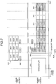
- FIG. 4 is a diagram illustrating in time series the data to be transmitted by using the respective frequency bands of the L-band and the U-band.
- data 301 in which the data addressed to three terminal devices UE #1 to #3 has been frequency-multiplexed is transmitted by a base station apparatus.
- DL assignment 302 concerning the data 301 is transmitted in the sub-frame identical to the respective data.
- the DL assignment 302 is the L-band DCI, and is arranged to the frequency in the EPDCCH area for example and transmitted.
- the terminal devices UE #1 to #3 each can understand, by receiving and decoding the DL assignment 302 in the EPDCCH area, which sub-band in the L-band the data addressed to the terminal devices themselves is allocated to.
- the U-band DCI is arranged and transmitted. That is, DL assignment 303 concerning the U-band and UL grant 304 are arranged to the frequency in the EPDCCH area.
- the terminal devices UE #1 to #3 each can understand, by receiving and decoding the DL assignment 303 in the EPDCCH area, which sub-band in the U-band the data addressed to the terminal devices themselves is allocated to.
- the terminal devices UE #1 to #3 can further understand, by receiving and decoding the UL grant 304 in the EPDCCH area, the presence of permission of data transmission of uplink using the U-band.
- the L-band DCI 302 and the U-band DCI 303 and 304 are arranged to the frequencies different from each other and transmitted.
- the base station apparatus can keep the L-band DCI 302 and the U-band DCI 303 and 304 mapped in advance and, depending on the result of carrier sense, transmit only the L-band DCI 302 and transmit the DCI on both bands.
- the base station apparatus transmits a dummy signal 352 up to the beginning of a subsequent sub-frame.
- the dummy signal 352 is a signal that occupies the frequency band of the U-band, and is transmitted to reserve the use of the U-band. That is, in order to prevent it from being determined that the U-band is vacant as a result of carrier sense executed by other devices, the dummy signal 352 is transmitted in the U-band.
- data 353 in which the data addressed to the terminal devices UE #1 to #3 has been frequency-multiplexed is transmitted by the base station apparatus.
- the DL assignment 303 concerning the data 353, as in the foregoing, is transmitted by using the EPDCCH of the L-band in the sub-frame identical to the respective data.
- a special sub-frame 354 is provided, and in the sub-frame after the special sub-frame 354, data 355 of uplink is transmitted.
- the terminal devices UE #1 to #3 execute scheduling by using the UL grant 304 transmitted using the EPDCCH of the L-band, and in accordance with the scheduling, the data 355 is transmitted.
- the L-band DCI and the U-band DCI are arranged to the frequencies different from each other in the EPDCCH area of the L-band and transmitted. Consequently, as a result of carrier sense, even when the transmission of data using the U-band is deferred, the L-band DCI mapped in advance can be transmitted independently from the U-band DCI. Furthermore, the U-band DCI mapped in advance is retained temporarily, and as a result of carrier sense, when the transmission of data using the U-band is executed, the retained U-band DCI can be transmitted. Accordingly, when the communication is performed by using a frequency band that needs a license and a frequency band that needs no license, it is possible to transmit the control information efficiently.
- the L-band DCI and the U-band DCI are arranged to different frequencies in the EPDCCH area of the L-band.
- the same effect can be obtained as long as they are being arranged to different areas.
- the feature of a second example is the point that the DL assignment indicative of the allocation of data of downlink in the U-band and the UL grant indicative of the transmission permission of data of uplink in the U-band are arranged to different frequencies.
- the configurations of the base station apparatus and the terminal device according to the second example are the same as those of the base station apparatus 100 and the terminal device 200 in the first example, and thus the explanations thereof are omitted.
- the operation of the EPDCCH generator 112 of the base station apparatus 100 is different from that of the first example.
- the EPDCCH generator 112 arranges, in an EPDCCH area of the L-band, the U-band DCI and the L-band DCI that are output from the U-band mapping unit 110 and the L-band mapping unit 111, respectively. At this time, the EPDCCH generator 112 allocates the REGs, in which the U-band DCI and the L-band DCI are mapped, to sub-carriers of frequencies different from each other in the EPDCCH area of the L-band. The EPDCCH generator 112 further allocates the REGs, in which the DL assignment and the UL grant out of the U-band DCI are mapped, to sub-carriers of frequencies different from each other in the EPDCCH area of the L-band.
- the L-band DCI, the DL assignment of the U-band, and the UL grant of the U-band are arranged to frequencies different from one another. Accordingly, even when the DL assignment of the U-band is output from the U-band mapping unit 110 while the UL grant of the U-band is not output for example, the EPDCCH generator 112 can allocate the L-band DCI and the DL assignment of the U-band to the sub-carriers in the EPDCCH area.
- FIG. 5 is a diagram illustrating in time series the data to be transmitted by using the respective frequency bands of the L-band and the U-band.
- the portions the same as those in FIG. 4 are denoted by the same reference signs, and the detailed explanations thereof are omitted.
- the data 301 in which the data addressed to the three terminal devices UE #1 to #3 has been frequency-multiplexed and the DL assignment 302 concerning the data 301 are transmitted.
- DL assignment 401 of the U-band and UL grant 402 are arranged and transmitted. That is, the DL assignment 401 and the UL grant 402 are arranged to the frequencies different from each other in the EPDCCH area.
- the terminal devices UE #1 to #3 each can understand, by receiving and decoding the DL assignment 401 in the EPDCCH area, which sub-band in the U-band the data addressed to the terminal devices themselves is allocated to.
- the terminal devices UE #1 to #3 can further understand, by receiving and decoding the UL grant 402 in the EPDCCH area, the presence of permission of data transmission of uplink using the U-band.
- the base station apparatus can keep the L-band DCI 302, the DL assignment 401 of the U-band, and the UL grant 402 of the U-band mapped in advance and, depending on the result of carrier sense, transmit only the L-band DCI 302 and transmit the DCI on both bands.
- the base station apparatus can also transmit only the DL assignment 401 out of the U-band DCI. Then, the base station apparatus can temporarily retain the UL grant 402 mapped in advance and, when the data transmission of uplink in the U-band is permitted, transmit the retained UL grant 402.
- the L-band DCI and the U-band DCI are arranged to the frequencies different from each other in the EPDCCH area of the L-band and transmitted. Furthermore, the DL assignment and the UL grant out of the U-band DCI also are arranged to the frequencies different from each other in the EPDCCH area. Consequently, as a result of carrier sense, even when the data transmission of uplink is not executed while the data transmission of downlink using the U-band is executed for example, the DL assignment mapped in advance can be transmitted independently from the UL grant.
- the UL grant mapped in advance can be retained temporarily, and as a result of carrier sense, when the data transmission of uplink using the U-band is executed, the retained U-band DCI can be transmitted. Accordingly, when the communication is performed by using a frequency band that needs a license and a frequency band that needs no license, it is possible to transmit the control information efficiently.
- the DL assignment and the UL grant included in the U-band DCI and the L-band DCI are arranged to different frequencies in the EPDCCH area of the L-band.
- the same effect can be obtained as long as they are being arranged to different areas.
- the feature of a third example is the point that the UL grant indicative of the transmission permission of data of uplink in the U-band is arranged in the U-band.
- the configurations of the base station apparatus and the terminal device according to the third example are the same as those of the base station apparatus 100 and the terminal device 200 in the first example, and thus the explanations thereof are omitted.
- the operation of the EPDCCH generator 112 of the base station apparatus 100 is different from that of the first example.
- the EPDCCH generator 112 arranges, in the EPDCCH area of the L-band and a certain control channel area of the U-band, the U-band DCI and the L-band DCI that are output from the U-band mapping unit 110 and the L-band mapping unit 111, respectively. At this time, the EPDCCH generator 112 allocates, to sub-carriers of frequencies different from each other in the EPDCCH area of the L-band, the REG in which the DL assignment out of the U-band DCI is mapped and the REG in which the L-band DCI is mapped. The EPDCCH generator 112 further allocates, to a sub-carrier in the certain control channel area of the U-band, the REG in which the UL grant out of the U-band DCI is mapped.
- the L-band DCI, the DL assignment of the U-band, and the UL grant of the U-band are arranged to the frequencies different from one another.
- the UL grant of the U-band is arranged not to the frequency in the EPDCCH area of the L-band but to a frequency in the certain control channel area of the U-band. Accordingly, it is possible to cut down the resources used in the EPDCCH of the L-band that needs a license, and to reduce the overhead.
- FIG. 6 is a diagram illustrating in time series the data to be transmitted by using the respective frequency bands of the L-band and the U-band.
- the portions the same as those in FIGS. 4 and 5 are denoted by the same reference signs, and the detailed explanations thereof are omitted.
- the data 301 in which the data addressed to the three terminal devices UE #1 to #3 has been frequency-multiplexed and the DL assignment 302 concerning the data 301 are transmitted.
- the DL assignment 401 of the U-band is arranged and transmitted.
- UL grant 501 of the U-band is arranged and transmitted. That is, the UL grant 501 is arranged not in the EPDCCH of the L-band but in the U-band.
- the terminal devices UE #1 to #3 each can understand, by receiving and decoding the DL assignment 401 in the EPDCCH area, which sub-band in the U-band the data addressed to the terminal devices themselves is allocated to.
- the terminal devices UE #1 to #3 can further understand, by receiving and decoding the UL grant 501 in the certain control channel area of the U-band, the presence of the permission of data transmission of uplink using the U-band.
- the L-band DCI 302 and the DL assignment 401 of the U-band are arranged to the frequencies different from each other and transmitted, and in the certain control channel area of the U-band, the UL grant 501 of the U-band is arranged and transmitted.
- the base station apparatus can keep the L-band DCI 302, the DL assignment 401 of the U-band, and the UL grant 501 of the U-band mapped in advance and, depending on the result of carrier sense, transmit only the L-band DCI 302 and transmit the DCI on both bands.
- the base station apparatus can also transmit only the DL assignment 401 out of the U-band DCI. Then, the base station apparatus can temporarily retain the UL grant 501 mapped in advance and, when the data transmission of uplink in the U-band is permitted, transmit the retained UL grant 501 by using the U-band.
- the L-band DCI and the U-band DCI are arranged to frequencies different from one another in the EPDCCH area of the L-band and the certain control channel area of the U-band and transmitted. Furthermore, the UL grant out of the U-band DCI is arranged in the certain control channel area of the U-band and transmitted. Accordingly, it is possible to cut down the DCI arranged in the EPDCCH area of the L-band, and to reduce the overhead in the EPDCCH.
- the L-band DCI and the DL assignment included in the U-band DCI are arranged to different frequencies in the EPDCCH area of the L-band.
- the same effect can be obtained as long as they are being arranged to different areas.
- the feature of a fourth example is the point that the DL assignment indicative of the allocation of data of downlink in the U-band and the UL grant indicative of the transmission permission of data of uplink in the U-band are arranged to different frequencies in the U-band.
- the configurations of the base station apparatus and the terminal device according to the fourth example are the same as those of the base station apparatus 100 and the terminal device 200 in the first example, and thus the explanations thereof are omitted.
- the operation of the EPDCCH generator 112 of the base station apparatus 100 is different from that of the first example.
- the EPDCCH generator 112 arranges, in the EPDCCH area of the L-band and a certain control channel area of the U-band, the U-band DCI and the L-band DCI that are output from the U-band mapping unit 110 and the L-band mapping unit 111, respectively. At this time, the EPDCCH generator 112 allocates the REG, in which the L-band DCI is mapped, to a sub-carrier in the EPDCCH area of the L-band. The EPDCCH generator 112 further allocates the REG, in which the U-band DCI is mapped, to sub-carriers of frequencies different from each other in the certain control channel area of the U-band. That is, the EPDCCH generator 112 arranges the DL assignment and the UL grant in the U-band to the frequencies different from each other in the certain control channel area of the U-band.
- the U-band DCI is arranged in the U-band.
- the DL assignment and the UL grant included in the U-band DCI are arranged to the frequencies different from each other in the certain control channel area. Accordingly, it is possible to cut down the resources used in the EPDCCH of the L-band that needs a license, and to reduce the overhead.
- FIG. 7 is a diagram illustrating in time series the data to be transmitted by using the respective frequency bands of the L-band and the U-band.
- the portions the same as those in FIG. 4 are denoted by the same reference signs, and the detailed explanations thereof are omitted.
- the data 301 in which the data addressed to the three terminal devices UE #1 to #3 has been frequency-multiplexed and the DL assignment 302 concerning the data 301 are transmitted.
- the DL assignment 302 is arranged in the EPDCCH area of the L-band and transmitted.
- the U-band DCI is arranged and transmitted.
- DL assignment 601 and UL grant 602 of the U-band are arranged to the frequencies different from each other in the certain control channel area of the U-band, and transmitted. That is, the DL assignment 601 and the UL grant 602 are arranged not in the EPDCCH area of the L-band but in the U-band.
- the terminal devices UE #1 to #3 each can understand, by receiving and decoding the DL assignment 601 in the certain control channel area of the U-band, which sub-band in the U-band the data addressed to the terminal devices themselves is allocated to.
- the terminal devices UE #1 to #3 can further understand, by receiving and decoding the UL grant 602 in the certain control channel area of the U-band, the presence of the permission of data transmission of uplink using the U-band.
- the L-band DCI 302 is arranged and transmitted, and in the certain control channel area of the U-band, the DL assignment 601 and the UL grant 602 of the U-band are arranged to the frequencies different from each other and transmitted.
- the base station apparatus can keep the L-band DCI 302, the DL assignment 601 of the U-band, and the UL grant 602 of the U-band mapped in advance and, depending on the result of carrier sense, transmit only the L-band DCI 302 and transmit the DCI on both bands.
- the base station apparatus can also transmit only the DL assignment 601 out of the U-band DCI. Then, the base station apparatus can temporarily retain the UL grant 602 mapped in advance and, when the data transmission of uplink in the U-band is permitted, transmit the retained UL grant 602 by using the U-band.
- the L-band DCI and the U-band DCI are arranged to the frequencies different from each other in the EPDCCH area of the L-band and the certain control channel area of the U-band and transmitted. Furthermore, the DL assignment and the UL grant included in the U-band DCI are arranged to the frequencies different from each other in the certain control channel area of the U-band. Accordingly, it is possible to cut down the DCI arranged in the EPDCCH area of the L-band, and to reduce the overhead in the EPDCCH.
- the DL assignment and the UL grant included in the U-band DCI are arranged to different frequencies in the certain control channel area of the U-band.
- the same effect can be obtained as long as they are being arranged to different areas.
- the feature of a fifth example is the point that the DL assignment indicative of the allocation of data of downlink in the U-band and the UL grant indicative of the transmission permission of data of uplink in the U-band are arranged to an identical frequency in the U-band.
- the configurations of the base station apparatus and the terminal device according to the fifth example are the same as those of the base station apparatus 100 and the terminal device 200 in the first example, and thus the explanations thereof are omitted.
- the operation of the EPDCCH generator 112 of the base station apparatus 100 is different from that of the first example.
- the EPDCCH generator 112 arranges, in the EPDCCH area of the L-band and a certain control channel area of the U-band, the U-band DCI and the L-band DCI that are output from the U-band mapping unit 110 and the L-band mapping unit 111, respectively. At this time, the EPDCCH generator 112 allocates the REG, in which the L-band DCI is mapped, to a sub-carrier in the EPDCCH area of the L-band. The EPDCCH generator 112 further allocates, to a sub-carrier in the certain control channel area of the U-band, the REG in which the U-band DCI is mapped. That is, the EPDCCH generator 112 time-multiplexes the DL assignment and the UL grant in the U-band and arranges them to an identical frequency in the certain control channel area of the U-band.
- the terminal device can understand, by decoding the U-band DCI in a single frequency in the certain control channel area of the U-band, the allocation location of data of downlink and the presence of the transmission permission of uplink.
- FIG. 8 is a diagram illustrating in time series the data to be transmitted by using the respective frequency bands of the L-band and the U-band.
- the portions the same as those in FIG. 4 are denoted by the same reference signs, and the detailed explanations thereof are omitted.
- the data 301 in which the data addressed to the three terminal devices UE #1 to #3 has been frequency-multiplexed and the DL assignment 302 concerning the data 301 are transmitted.
- the DL assignment 302 is arranged in the EPDCCH area of the L-band and transmitted.
- the U-band DCI is arranged and transmitted.
- DL assignment 701 and UL grant 702 of the U-band are time-multiplexed, and are arranged to an identical frequency in the certain control channel area of the U-band and transmitted. That is, the DL assignment 701 and the UL grant 702 are arranged not in the EPDCCH area of the L-band but in the U-band.
- the terminal devices UE #1 to #3 each can understand, by receiving and decoding the DL assignment 701 in the certain control channel area of the U-band, which sub-band in the U-band the data addressed to the terminal devices themselves is allocated to.
- the terminal devices UE #1 to #3 can further understand, by receiving and decoding the UL grant 702 in the certain control channel area of the U-band, the presence of the permission of data transmission of uplink using the U-band.
- the L-band DCI 302 is arranged and transmitted, and in the certain control channel area of the U-band, the DL assignment 701 and the UL grant 702 of the U-band are arranged to an identical frequency and transmitted.
- the base station apparatus can keep the L-band DCI 302, the DL assignment 701 of the U-band, and the UL grant 702 of the U-band mapped in advance and, depending on the result of carrier sense, transmit only the L-band DCI 302 and transmit the DCI on both bands. That is, when the U-band is not vacant as a result of carrier sense for example, the base station apparatus can transmit only the L-band DCI 302.
- the base station apparatus can temporarily retain the DL assignment 701 and the UL grant 702 that are of the U-band and are mapped in advance and, when the U-band turns vacant, transmit the retained DL assignment 701 and the UL grant 702 by using the U-band.
- the L-band DCI and the U-band DCI are arranged to the frequencies different from each other in the EPDCCH area of the L-band and the certain control channel area of the U-band and transmitted. Furthermore, the DL assignment and the UL grant included in the U-band DCI are arranged to the identical frequency in the certain control channel area of the U-band and transmitted. Accordingly, it is possible to cut down the DCI arranged in the EPDCCH area of the L-band, and to reduce the overhead in the EPDCCH.
- the terminal device can decode the DL assignment and the UL grant from a single frequency of the U-band.
- the DL assignment and the UL grant included in the U-band DCI are arranged to an identical frequency in the certain control channel area of the U-band.
- the same effect can be obtained as long as they are being arranged to an identical area.
- the transmission processing of the DCI explained in the above-described respective examples can be executed, by a base station apparatus 800 having a hardware configuration that is illustrated in FIG. 9 , for example.
- the base station apparatus 800 illustrated in FIG. 9 includes a wireless unit 801, a baseband processor (hereinafter abbreviated as "BB processor") 802, an application processor (hereinafter abbreviated as "AP processor”) 803, and a memory 804.
- BB processor baseband processor
- AP processor application processor
- the wireless unit 801 transmits a wireless signal including the DCI via an antenna.
- the wireless unit 801 receives a wireless signal via the antenna.
- the wireless unit 801 then executes certain wireless transmitting processing and executes certain wireless receiving processing.
- the wireless unit 801 corresponds to the L-band receiver 101, the U-band receiver 102, the L-band transmitter 117, and the U-band transmitter 118 of the base station apparatus 100 illustrated in FIG. 1 , for example.
- the BB processor 802 executes baseband processing on the signal transmitted and received. That is, the BB processor 802 executes modulation and demodulation, and encoding and decoding of signals, for example.
- the BB processor 802 corresponds to the CP removal units 103 and 104, the FFT units 105 and 106, the channel separator 107, the decoder 108, the U-band vacancy determining unit 109, the U-band mapping unit 110, the L-band mapping unit 111, the EPDCCH generator 112, the IFFT units 113 and 114, and the CP adding units 115 and 116 of the base station apparatus 100 illustrated in FIG. 1 , for example.
- the AP processor 803 executes processing of applications. That is, the AP processor 803 executes the processing using decoded data obtained in the BB processor 802 and executes the processing of determining the content of the DCI.
- the memory 804 stores therein data and others that are used when the AP processor 803 executes the processing.
Landscapes
- Engineering & Computer Science (AREA)
- Signal Processing (AREA)
- Computer Networks & Wireless Communication (AREA)
- Mobile Radio Communication Systems (AREA)
Claims (9)
- Système de communication sans fil comprenant :un appareil de station de base (100) ; etun dispositif terminal (200),l'appareil de station de base (100) comprenant :une première unité de mise en correspondance (111) configurée pour mettre en correspondance des premières informations de commande indicatives de l'attribution de données de liaison descendante dans une première bande de fréquences qui nécessite une licence pour une utilisation pour une communication sans fil,une seconde unité de mise en correspondance (110) configurée pour mettre en correspondance des secondes informations de commande indicatives de la présence d'une autorisation de transmission de données de liaison montante dans une seconde bande de fréquences qui n'a pas besoin de la licence pour une utilisation pour une communication sans fil,un générateur (112) configuré pour générer un signal de canal de commande en disposant les premières informations de commande et les secondes informations de commande sur différentes régions de ressources radio dans un canal de commande de la première bande de fréquences, etun transmetteur (117, 118) configuré pour transmettre le signal de canal de commande généré par le générateur (112) au dispositif terminal (200).
- Système de communication sans fil selon la revendication 1, dans lequel
l'appareil de station de base (100) comprend en outre une unité de détermination (109) configurée pour déterminer si l'énergie reçue dans la seconde bande de fréquences est inférieure à un seuil prédéterminé, et
le générateur (112) est configuré pour générer le signal de canal de commande en disposant les premières informations de commande et les secondes informations de commande dans différentes régions de ressources radio lorsque l'unité de détermination (109) détermine que l'énergie reçue est inférieure au seuil prédéterminé. - Système de communication sans fil selon la revendication 2, dans lequel la seconde unité de mise en correspondance (110) est configurée pour conserver les secondes informations mises en correspondance lorsque l'unité de détermination (109) détermine que l'énergie reçue n'est pas inférieure au seuil prédéterminé.
- Système de communication sans fil selon la revendication 1, dans lequel
la seconde unité de mise en correspondance (110) est configurée pour mettre en correspondance les secondes informations de commande, y compris des informations de commande de liaison descendante indicatives de l'attribution de données de liaison descendante dans la seconde bande de fréquences et d'informations de commande de liaison montante indicatives de la présence d'une autorisation de transmission de données de liaison montante dans la seconde bande de fréquences, et
le générateur (112) est configuré pour générer le signal de canal de commande en disposant les informations de commande de liaison descendante et les informations de commande de liaison montante sur une région de ressources radio dans le canal de commande de la première bande de fréquences qui est différente d'une région de ressources radio sur laquelle les premières informations de commande sont disposées. - Système de communication sans fil selon la revendication 4, dans lequel le générateur (112) est configuré pour générer le signal de canal de commande en disposant les informations de commande de liaison descendante et les informations de commande de liaison montante dans une sous-porteuse dans le canal de commande de la première bande de fréquences.
- Système de communication sans fil selon la revendication 4, dans lequel le générateur (112) est configuré pour générer le signal de canal de commande en disposant les informations de commande de liaison descendante et les informations de commande de liaison montante dans différentes sous-porteuses dans le canal de commande de la première bande de fréquences.
- Appareil de station de base (100) comprenant :une première unité de mise en correspondance (111) configurée pour mettre en correspondance des premières informations de commande indicatives de l'attribution de donnée de liaison descendante dans une première bande de fréquences qui nécessite une licence pour une utilisation pour une communication sans fil,une seconde unité de mise en correspondance (100) configurée pour mettre en correspondance des secondes informations de commande indicatives de la présence d'une autorisation de transmission de données de liaison montante dans une seconde bande de fréquences qui n'a pas besoin de la licence pour une utilisation pour une communication sans fil,un générateur (112) pour générer un signal de canal de commande en disposant les premières informations de commande et les secondes informations de commande sur différentes régions de ressources radio dans un canal de commande de la première bande de fréquences, etun transmetteur (117, 118) pour transmettre le signal de canal de commande généré par le générateur (112).
- Dispositif terminal (200) comprenant :un récepteur (201) configuré pour recevoir un signal de canal de commande dans lequel des premières informations de commande et des secondes informations de commande sont disposées sur différentes régions de ressources radio dans un canal de commande dans une première bande de fréquences, les premières informations de commande étant indicatives d'une attribution de données de liaison descendante dans la première bande de fréquences qui nécessite une licence d'utilisation pour une communication sans fil, et les secondes informations de commande indiquant la présence d'une autorisation de transmission de données de liaison montante dans une seconde bande de fréquence qui n'a pas besoin de la licence d'utilisation pour la communication sans fil ; etun décodeur (207) configuré pour décoder le signal de canal de commande reçu par le récepteur (201) et, sur la base d'un résultat de décodage, décoder des données reçues dans la première bande de fréquences.
- Procédé de transmission exécuté dans un appareil de station de base (100) appartenant à un système de communication sans fil, le procédé de transmission comprenant les étapes consistant à :mettre en correspondance des premières informations de commande indicatives d'une attribution de données de liaison descendante dans une première bande de fréquences qui nécessite une licence pour une utilisation pour une communication sans fil ;mettre en correspondance des secondes informations de commande indiquant la présence d'une autorisation de transmission de données de liaison montante dans une seconde bande de fréquences qui n'a pas besoin de la licence d'utilisation pour la communication sans fil ;générer un signal de canal de commande en disposant les premières informations de commande et les secondes informations de commande sur différentes régions de ressources radio dans un canal de commande de la première bande de fréquences ; ettransmettre le signal de canal de commande généré.
Applications Claiming Priority (1)
| Application Number | Priority Date | Filing Date | Title |
|---|---|---|---|
| PCT/JP2014/079374 WO2016071976A1 (fr) | 2014-11-05 | 2014-11-05 | Système de communication sans fil, dispositif station de base, dispositif terminal et procédé de transmission |
Publications (3)
| Publication Number | Publication Date |
|---|---|
| EP3217743A1 EP3217743A1 (fr) | 2017-09-13 |
| EP3217743A4 EP3217743A4 (fr) | 2017-10-11 |
| EP3217743B1 true EP3217743B1 (fr) | 2019-12-11 |
Family
ID=55908729
Family Applications (1)
| Application Number | Title | Priority Date | Filing Date |
|---|---|---|---|
| EP14905386.0A Active EP3217743B1 (fr) | 2014-11-05 | 2014-11-05 | Système de communication sans fil, dispositif station de base, dispositif terminal et procédé de transmission |
Country Status (11)
| Country | Link |
|---|---|
| US (1) | US9942915B2 (fr) |
| EP (1) | EP3217743B1 (fr) |
| JP (1) | JP6455521B2 (fr) |
| KR (1) | KR101998001B1 (fr) |
| CN (1) | CN107079425B (fr) |
| AU (1) | AU2014410902B2 (fr) |
| BR (1) | BR112017008230A2 (fr) |
| CA (1) | CA2965947A1 (fr) |
| MX (1) | MX358707B (fr) |
| RU (1) | RU2659480C1 (fr) |
| WO (1) | WO2016071976A1 (fr) |
Families Citing this family (6)
| Publication number | Priority date | Publication date | Assignee | Title |
|---|---|---|---|---|
| KR100466123B1 (ko) * | 2002-10-16 | 2005-01-13 | 현대자동차주식회사 | 차량의 브레이크패드의 분진 여과 장치 |
| KR102704106B1 (ko) * | 2019-03-19 | 2024-09-06 | 현대자동차주식회사 | 디스크브레이크의 마찰재 마모분진 유해성 저감장치 및 방법 |
| US11187288B2 (en) * | 2019-07-31 | 2021-11-30 | Federal-Mogul Motorparts Llc | Vehicle brake component for collecting brake dust |
| KR102261576B1 (ko) * | 2019-12-31 | 2021-06-07 | 호남대학교 산학협력단 | 차량의 브레이크 분진 채집장치 |
| CN115412593B (zh) * | 2021-05-14 | 2024-04-16 | 海能达通信股份有限公司 | 调整功能权限的方法、控制方法、装置、设备及存储介质 |
| KR102558068B1 (ko) * | 2021-06-17 | 2023-07-25 | 한국기계연구원 | 브레이크 패드 마모에 의한 분진 제거장치 |
Family Cites Families (20)
| Publication number | Priority date | Publication date | Assignee | Title |
|---|---|---|---|---|
| JP2873320B2 (ja) * | 1989-09-19 | 1999-03-24 | 日本電信電話株式会社 | 移動局の在圏セクタ判定方式 |
| JP2748656B2 (ja) * | 1990-06-19 | 1998-05-13 | ソニー株式会社 | 移動無線通信方法 |
| JP2002124916A (ja) | 2000-10-13 | 2002-04-26 | Nec Corp | Point−to−Multipoint無線アクセス・システム |
| US7996009B2 (en) * | 2001-02-26 | 2011-08-09 | Kineto Wireless, Inc. | Method for authenticating access to an unlicensed wireless communications system using a licensed wireless communications system authentication process |
| CN101730180A (zh) * | 2002-10-18 | 2010-06-09 | 卡耐特无线有限公司 | 扩展有执照无线通信系统覆盖区域的装置与方法 |
| JP4908410B2 (ja) | 2004-07-30 | 2012-04-04 | コーニンクレッカ フィリップス エレクトロニクス エヌ ヴィ | 複数の物理伝送レートの無線システムで公平なスペクトル共有を提供する方法及び装置 |
| US7440728B2 (en) | 2004-12-03 | 2008-10-21 | Microsoft Corporation | Use of separate control channel to mitigate interference problems in wireless networking |
| JP4430052B2 (ja) * | 2006-06-19 | 2010-03-10 | 株式会社エヌ・ティ・ティ・ドコモ | 移動通信システム、ユーザ装置及び送信方法 |
| JP4531784B2 (ja) * | 2007-03-20 | 2010-08-25 | 株式会社エヌ・ティ・ティ・ドコモ | ユーザ装置および送信方法 |
| KR20110113542A (ko) * | 2010-04-09 | 2011-10-17 | 주식회사 팬택 | 채널 추정 기준 신호의 확장 전송 방법 및 이를 이용한 채널 추정 기준 신호의 송수신 방법 및 장치 |
| EP3742656A1 (fr) | 2010-12-06 | 2020-11-25 | Interdigital Patent Holdings, Inc. | Procédé permettant un fonctionnement sans fil dans un spectre exempt de licence |
| KR101600487B1 (ko) * | 2011-04-18 | 2016-03-21 | 엘지전자 주식회사 | 무선통신시스템에서 신호 전송 방법 및 장치 |
| GB2493154A (en) * | 2011-07-25 | 2013-01-30 | Nec Corp | Communicating control channel reference signal patterns in the control region of a sub-frame in a cellular communication system |
| JP5905469B2 (ja) * | 2011-08-10 | 2016-04-20 | パナソニック インテレクチュアル プロパティ コーポレーション オブ アメリカPanasonic Intellectual Property Corporation of America | 端末装置、応答信号送信方法及び集積回路 |
| CN103959893B (zh) * | 2011-12-02 | 2018-01-26 | 诺基亚技术有限公司 | 用于多模通信的方法和装置 |
| GB2497780B (en) * | 2011-12-21 | 2014-02-26 | Broadcom Corp | Apparatus and methods for performing sensing operations in carrier aggregation communications |
| WO2013131268A1 (fr) * | 2012-03-08 | 2013-09-12 | Renesas Mobile Corporation | Appareil et procédés d'amélioration de fiabilité de pdcch pour gérer une porteuse composante de liaison descendante scindée dans une bande sans licence |
| US8874124B2 (en) * | 2012-06-14 | 2014-10-28 | Netgear, Inc. | Dual band LTE small cell |
| TWI632823B (zh) * | 2012-08-23 | 2018-08-11 | 內數位專利控股公司 | 在無線系統中多層操作之實體層操作 |
| US11431459B2 (en) * | 2013-08-13 | 2022-08-30 | Qualcomm Incorporated | Group ACK/NACK for LTE in unlicensed spectrum |
-
2014
- 2014-11-05 CA CA2965947A patent/CA2965947A1/fr not_active Abandoned
- 2014-11-05 CN CN201480083178.5A patent/CN107079425B/zh active Active
- 2014-11-05 BR BR112017008230-6A patent/BR112017008230A2/pt not_active IP Right Cessation
- 2014-11-05 EP EP14905386.0A patent/EP3217743B1/fr active Active
- 2014-11-05 MX MX2017005523A patent/MX358707B/es active IP Right Grant
- 2014-11-05 KR KR1020177011368A patent/KR101998001B1/ko active Active
- 2014-11-05 RU RU2017114657A patent/RU2659480C1/ru active
- 2014-11-05 AU AU2014410902A patent/AU2014410902B2/en not_active Ceased
- 2014-11-05 JP JP2016557387A patent/JP6455521B2/ja active Active
- 2014-11-05 WO PCT/JP2014/079374 patent/WO2016071976A1/fr not_active Ceased
-
2017
- 2017-04-12 US US15/485,649 patent/US9942915B2/en active Active
Non-Patent Citations (1)
| Title |
|---|
| LG ELECTRONICS: "Further consideration on EPDCCH design", vol. RAN WG1, no. New Orleans, USA; 20121112 - 20121116, 3 November 2012 (2012-11-03), XP050662903, Retrieved from the Internet <URL:http://www.3gpp.org/ftp/tsg_ran/WG1_RL1/TSGR1_71/Docs/> [retrieved on 20121103] * |
Also Published As
| Publication number | Publication date |
|---|---|
| CN107079425A (zh) | 2017-08-18 |
| CA2965947A1 (fr) | 2016-05-12 |
| US9942915B2 (en) | 2018-04-10 |
| EP3217743A4 (fr) | 2017-10-11 |
| US20170223724A1 (en) | 2017-08-03 |
| JPWO2016071976A1 (ja) | 2017-07-20 |
| MX358707B (es) | 2018-08-31 |
| RU2659480C1 (ru) | 2018-07-02 |
| CN107079425B (zh) | 2020-04-07 |
| KR101998001B1 (ko) | 2019-07-08 |
| MX2017005523A (es) | 2017-06-20 |
| JP6455521B2 (ja) | 2019-01-23 |
| EP3217743A1 (fr) | 2017-09-13 |
| AU2014410902B2 (en) | 2018-04-05 |
| KR20170066479A (ko) | 2017-06-14 |
| AU2014410902A1 (en) | 2017-05-18 |
| BR112017008230A2 (pt) | 2019-05-14 |
| WO2016071976A1 (fr) | 2016-05-12 |
Similar Documents
| Publication | Publication Date | Title |
|---|---|---|
| US20200163128A1 (en) | Random access configuration method, network device, and terminal device | |
| CN109803402B (zh) | 信息发送、接收方法及装置 | |
| CN110266462B (zh) | 发射机传输方法和由接收机通过未授权带信道执行的方法 | |
| KR102321890B1 (ko) | 시간-주파수 자원의 송신 방향을 구성하는 방법, 및 장치 | |
| EP2945454B1 (fr) | Procédés et dispositifs d'envoi d'informations de commande et de réception d'informations de commande | |
| US9942915B2 (en) | Wireless communication system, base station apparatus, terminal device, and transmission method | |
| RU2718157C1 (ru) | Способ указания ресурса и связанные устройство и система | |
| CN105657849B (zh) | 在通信网络中调度允许发送信令的方法和装置 | |
| CN110958098A (zh) | 配置旁链路资源的方法和装置 | |
| CN114731635B (zh) | 用于无线通信的方法及设备 | |
| JP6356793B2 (ja) | データスケジューリング方法、データスケジューリング装置、基地局、および端末装置 | |
| US11038641B2 (en) | Pilot-data overlap design for uplink transmission | |
| US10425923B2 (en) | Uplink channel multiplexing and waveform selection | |
| CN110546990B (zh) | 速率匹配的指示方法、装置、设备及存储介质 | |
| EP3114790B1 (fr) | Dispositif de communication pour communication lte dans des canaux gsm inexploités | |
| EP3439405B1 (fr) | Procédé, dispositif, et système de programmation de sous-trames multiples | |
| CN110537386B (zh) | 同步广播块的发送方法、接收方法、装置、设备及介质 | |
| US12538352B2 (en) | Communication method and user equipment | |
| WO2020164635A1 (fr) | Procédé et dispositif de transmission de signal initial | |
| KR102199873B1 (ko) | 무선 통신 방법 및 장치 | |
| US20190159183A1 (en) | Base station, user equipment, and communication control method |
Legal Events
| Date | Code | Title | Description |
|---|---|---|---|
| STAA | Information on the status of an ep patent application or granted ep patent |
Free format text: STATUS: THE INTERNATIONAL PUBLICATION HAS BEEN MADE |
|
| PUAI | Public reference made under article 153(3) epc to a published international application that has entered the european phase |
Free format text: ORIGINAL CODE: 0009012 |
|
| STAA | Information on the status of an ep patent application or granted ep patent |
Free format text: STATUS: REQUEST FOR EXAMINATION WAS MADE |
|
| 17P | Request for examination filed |
Effective date: 20170407 |
|
| AK | Designated contracting states |
Kind code of ref document: A1 Designated state(s): AL AT BE BG CH CY CZ DE DK EE ES FI FR GB GR HR HU IE IS IT LI LT LU LV MC MK MT NL NO PL PT RO RS SE SI SK SM TR |
|
| AX | Request for extension of the european patent |
Extension state: BA ME |
|
| A4 | Supplementary search report drawn up and despatched |
Effective date: 20170908 |
|
| RIC1 | Information provided on ipc code assigned before grant |
Ipc: H04W 16/14 20090101ALI20170904BHEP Ipc: H04W 88/06 20090101ALI20170904BHEP Ipc: H04W 88/10 20090101ALI20170904BHEP Ipc: H04W 72/04 20090101AFI20170904BHEP |
|
| DAX | Request for extension of the european patent (deleted) | ||
| STAA | Information on the status of an ep patent application or granted ep patent |
Free format text: STATUS: EXAMINATION IS IN PROGRESS |
|
| 17Q | First examination report despatched |
Effective date: 20180705 |
|
| GRAP | Despatch of communication of intention to grant a patent |
Free format text: ORIGINAL CODE: EPIDOSNIGR1 |
|
| STAA | Information on the status of an ep patent application or granted ep patent |
Free format text: STATUS: GRANT OF PATENT IS INTENDED |
|
| INTG | Intention to grant announced |
Effective date: 20190723 |
|
| GRAS | Grant fee paid |
Free format text: ORIGINAL CODE: EPIDOSNIGR3 |
|
| GRAA | (expected) grant |
Free format text: ORIGINAL CODE: 0009210 |
|
| STAA | Information on the status of an ep patent application or granted ep patent |
Free format text: STATUS: THE PATENT HAS BEEN GRANTED |
|
| AK | Designated contracting states |
Kind code of ref document: B1 Designated state(s): AL AT BE BG CH CY CZ DE DK EE ES FI FR GB GR HR HU IE IS IT LI LT LU LV MC MK MT NL NO PL PT RO RS SE SI SK SM TR |
|
| REG | Reference to a national code |
Ref country code: GB Ref legal event code: FG4D |
|
| REG | Reference to a national code |
Ref country code: CH Ref legal event code: EP |
|
| REG | Reference to a national code |
Ref country code: AT Ref legal event code: REF Ref document number: 1213477 Country of ref document: AT Kind code of ref document: T Effective date: 20191215 |
|
| REG | Reference to a national code |
Ref country code: IE Ref legal event code: FG4D |
|
| REG | Reference to a national code |
Ref country code: DE Ref legal event code: R096 Ref document number: 602014058436 Country of ref document: DE |
|
| REG | Reference to a national code |
Ref country code: NL Ref legal event code: MP Effective date: 20191211 |
|
| REG | Reference to a national code |
Ref country code: LT Ref legal event code: MG4D |
|
| PG25 | Lapsed in a contracting state [announced via postgrant information from national office to epo] |
Ref country code: FI Free format text: LAPSE BECAUSE OF FAILURE TO SUBMIT A TRANSLATION OF THE DESCRIPTION OR TO PAY THE FEE WITHIN THE PRESCRIBED TIME-LIMIT Effective date: 20191211 Ref country code: BG Free format text: LAPSE BECAUSE OF FAILURE TO SUBMIT A TRANSLATION OF THE DESCRIPTION OR TO PAY THE FEE WITHIN THE PRESCRIBED TIME-LIMIT Effective date: 20200311 Ref country code: LT Free format text: LAPSE BECAUSE OF FAILURE TO SUBMIT A TRANSLATION OF THE DESCRIPTION OR TO PAY THE FEE WITHIN THE PRESCRIBED TIME-LIMIT Effective date: 20191211 Ref country code: GR Free format text: LAPSE BECAUSE OF FAILURE TO SUBMIT A TRANSLATION OF THE DESCRIPTION OR TO PAY THE FEE WITHIN THE PRESCRIBED TIME-LIMIT Effective date: 20200312 Ref country code: SE Free format text: LAPSE BECAUSE OF FAILURE TO SUBMIT A TRANSLATION OF THE DESCRIPTION OR TO PAY THE FEE WITHIN THE PRESCRIBED TIME-LIMIT Effective date: 20191211 Ref country code: NO Free format text: LAPSE BECAUSE OF FAILURE TO SUBMIT A TRANSLATION OF THE DESCRIPTION OR TO PAY THE FEE WITHIN THE PRESCRIBED TIME-LIMIT Effective date: 20200311 Ref country code: LV Free format text: LAPSE BECAUSE OF FAILURE TO SUBMIT A TRANSLATION OF THE DESCRIPTION OR TO PAY THE FEE WITHIN THE PRESCRIBED TIME-LIMIT Effective date: 20191211 |
|
| PG25 | Lapsed in a contracting state [announced via postgrant information from national office to epo] |
Ref country code: RS Free format text: LAPSE BECAUSE OF FAILURE TO SUBMIT A TRANSLATION OF THE DESCRIPTION OR TO PAY THE FEE WITHIN THE PRESCRIBED TIME-LIMIT Effective date: 20191211 Ref country code: HR Free format text: LAPSE BECAUSE OF FAILURE TO SUBMIT A TRANSLATION OF THE DESCRIPTION OR TO PAY THE FEE WITHIN THE PRESCRIBED TIME-LIMIT Effective date: 20191211 |
|
| PG25 | Lapsed in a contracting state [announced via postgrant information from national office to epo] |
Ref country code: AL Free format text: LAPSE BECAUSE OF FAILURE TO SUBMIT A TRANSLATION OF THE DESCRIPTION OR TO PAY THE FEE WITHIN THE PRESCRIBED TIME-LIMIT Effective date: 20191211 |
|
| PG25 | Lapsed in a contracting state [announced via postgrant information from national office to epo] |
Ref country code: ES Free format text: LAPSE BECAUSE OF FAILURE TO SUBMIT A TRANSLATION OF THE DESCRIPTION OR TO PAY THE FEE WITHIN THE PRESCRIBED TIME-LIMIT Effective date: 20191211 Ref country code: NL Free format text: LAPSE BECAUSE OF FAILURE TO SUBMIT A TRANSLATION OF THE DESCRIPTION OR TO PAY THE FEE WITHIN THE PRESCRIBED TIME-LIMIT Effective date: 20191211 Ref country code: RO Free format text: LAPSE BECAUSE OF FAILURE TO SUBMIT A TRANSLATION OF THE DESCRIPTION OR TO PAY THE FEE WITHIN THE PRESCRIBED TIME-LIMIT Effective date: 20191211 Ref country code: CZ Free format text: LAPSE BECAUSE OF FAILURE TO SUBMIT A TRANSLATION OF THE DESCRIPTION OR TO PAY THE FEE WITHIN THE PRESCRIBED TIME-LIMIT Effective date: 20191211 Ref country code: PT Free format text: LAPSE BECAUSE OF FAILURE TO SUBMIT A TRANSLATION OF THE DESCRIPTION OR TO PAY THE FEE WITHIN THE PRESCRIBED TIME-LIMIT Effective date: 20200506 Ref country code: EE Free format text: LAPSE BECAUSE OF FAILURE TO SUBMIT A TRANSLATION OF THE DESCRIPTION OR TO PAY THE FEE WITHIN THE PRESCRIBED TIME-LIMIT Effective date: 20191211 |
|
| PG25 | Lapsed in a contracting state [announced via postgrant information from national office to epo] |
Ref country code: IS Free format text: LAPSE BECAUSE OF FAILURE TO SUBMIT A TRANSLATION OF THE DESCRIPTION OR TO PAY THE FEE WITHIN THE PRESCRIBED TIME-LIMIT Effective date: 20200411 Ref country code: SK Free format text: LAPSE BECAUSE OF FAILURE TO SUBMIT A TRANSLATION OF THE DESCRIPTION OR TO PAY THE FEE WITHIN THE PRESCRIBED TIME-LIMIT Effective date: 20191211 Ref country code: SM Free format text: LAPSE BECAUSE OF FAILURE TO SUBMIT A TRANSLATION OF THE DESCRIPTION OR TO PAY THE FEE WITHIN THE PRESCRIBED TIME-LIMIT Effective date: 20191211 |
|
| REG | Reference to a national code |
Ref country code: DE Ref legal event code: R097 Ref document number: 602014058436 Country of ref document: DE |
|
| REG | Reference to a national code |
Ref country code: AT Ref legal event code: MK05 Ref document number: 1213477 Country of ref document: AT Kind code of ref document: T Effective date: 20191211 |
|
| PLBE | No opposition filed within time limit |
Free format text: ORIGINAL CODE: 0009261 |
|
| STAA | Information on the status of an ep patent application or granted ep patent |
Free format text: STATUS: NO OPPOSITION FILED WITHIN TIME LIMIT |
|
| PG25 | Lapsed in a contracting state [announced via postgrant information from national office to epo] |
Ref country code: DK Free format text: LAPSE BECAUSE OF FAILURE TO SUBMIT A TRANSLATION OF THE DESCRIPTION OR TO PAY THE FEE WITHIN THE PRESCRIBED TIME-LIMIT Effective date: 20191211 |
|
| 26N | No opposition filed |
Effective date: 20200914 |
|
| PG25 | Lapsed in a contracting state [announced via postgrant information from national office to epo] |
Ref country code: AT Free format text: LAPSE BECAUSE OF FAILURE TO SUBMIT A TRANSLATION OF THE DESCRIPTION OR TO PAY THE FEE WITHIN THE PRESCRIBED TIME-LIMIT Effective date: 20191211 Ref country code: SI Free format text: LAPSE BECAUSE OF FAILURE TO SUBMIT A TRANSLATION OF THE DESCRIPTION OR TO PAY THE FEE WITHIN THE PRESCRIBED TIME-LIMIT Effective date: 20191211 |
|
| REG | Reference to a national code |
Ref country code: DE Ref legal event code: R082 Ref document number: 602014058436 Country of ref document: DE Representative=s name: HL KEMPNER PATENTANWAELTE, SOLICITORS (ENGLAND, DE Ref country code: DE Ref legal event code: R082 Ref document number: 602014058436 Country of ref document: DE Representative=s name: HL KEMPNER PATENTANWALT, RECHTSANWALT, SOLICIT, DE Ref country code: DE Ref legal event code: R082 Ref document number: 602014058436 Country of ref document: DE Representative=s name: HL KEMPNER PARTG MBB, DE |
|
| PG25 | Lapsed in a contracting state [announced via postgrant information from national office to epo] |
Ref country code: IT Free format text: LAPSE BECAUSE OF FAILURE TO SUBMIT A TRANSLATION OF THE DESCRIPTION OR TO PAY THE FEE WITHIN THE PRESCRIBED TIME-LIMIT Effective date: 20191211 |
|
| PG25 | Lapsed in a contracting state [announced via postgrant information from national office to epo] |
Ref country code: PL Free format text: LAPSE BECAUSE OF FAILURE TO SUBMIT A TRANSLATION OF THE DESCRIPTION OR TO PAY THE FEE WITHIN THE PRESCRIBED TIME-LIMIT Effective date: 20191211 |
|
| PG25 | Lapsed in a contracting state [announced via postgrant information from national office to epo] |
Ref country code: MC Free format text: LAPSE BECAUSE OF FAILURE TO SUBMIT A TRANSLATION OF THE DESCRIPTION OR TO PAY THE FEE WITHIN THE PRESCRIBED TIME-LIMIT Effective date: 20191211 |
|
| REG | Reference to a national code |
Ref country code: CH Ref legal event code: PL |
|
| PG25 | Lapsed in a contracting state [announced via postgrant information from national office to epo] |
Ref country code: LU Free format text: LAPSE BECAUSE OF NON-PAYMENT OF DUE FEES Effective date: 20201105 |
|
| REG | Reference to a national code |
Ref country code: BE Ref legal event code: MM Effective date: 20201130 |
|
| PG25 | Lapsed in a contracting state [announced via postgrant information from national office to epo] |
Ref country code: CH Free format text: LAPSE BECAUSE OF NON-PAYMENT OF DUE FEES Effective date: 20201130 Ref country code: LI Free format text: LAPSE BECAUSE OF NON-PAYMENT OF DUE FEES Effective date: 20201130 |
|
| PG25 | Lapsed in a contracting state [announced via postgrant information from national office to epo] |
Ref country code: IE Free format text: LAPSE BECAUSE OF NON-PAYMENT OF DUE FEES Effective date: 20201105 |
|
| PG25 | Lapsed in a contracting state [announced via postgrant information from national office to epo] |
Ref country code: TR Free format text: LAPSE BECAUSE OF FAILURE TO SUBMIT A TRANSLATION OF THE DESCRIPTION OR TO PAY THE FEE WITHIN THE PRESCRIBED TIME-LIMIT Effective date: 20191211 Ref country code: MT Free format text: LAPSE BECAUSE OF FAILURE TO SUBMIT A TRANSLATION OF THE DESCRIPTION OR TO PAY THE FEE WITHIN THE PRESCRIBED TIME-LIMIT Effective date: 20191211 Ref country code: CY Free format text: LAPSE BECAUSE OF FAILURE TO SUBMIT A TRANSLATION OF THE DESCRIPTION OR TO PAY THE FEE WITHIN THE PRESCRIBED TIME-LIMIT Effective date: 20191211 |
|
| PG25 | Lapsed in a contracting state [announced via postgrant information from national office to epo] |
Ref country code: MK Free format text: LAPSE BECAUSE OF FAILURE TO SUBMIT A TRANSLATION OF THE DESCRIPTION OR TO PAY THE FEE WITHIN THE PRESCRIBED TIME-LIMIT Effective date: 20191211 |
|
| PG25 | Lapsed in a contracting state [announced via postgrant information from national office to epo] |
Ref country code: BE Free format text: LAPSE BECAUSE OF NON-PAYMENT OF DUE FEES Effective date: 20201130 |
|
| REG | Reference to a national code |
Ref country code: DE Ref legal event code: R081 Ref document number: 602014058436 Country of ref document: DE Owner name: 1FINITY INC., KAWASAKI-SHI, JP Free format text: FORMER OWNER: FUJITSU LIMITED, KAWASAKI-SHI, KANAGAWA, JP |
|
| REG | Reference to a national code |
Ref country code: GB Ref legal event code: 732E Free format text: REGISTERED BETWEEN 20251127 AND 20251203 |
|
| PGFP | Annual fee paid to national office [announced via postgrant information from national office to epo] |
Ref country code: DE Payment date: 20251022 Year of fee payment: 12 |
|
| PGFP | Annual fee paid to national office [announced via postgrant information from national office to epo] |
Ref country code: GB Payment date: 20251022 Year of fee payment: 12 |
|
| PGFP | Annual fee paid to national office [announced via postgrant information from national office to epo] |
Ref country code: FR Payment date: 20251023 Year of fee payment: 12 |