EP3217832B1 - Valise présentant des caractéristiques de surface offrant une meilleure résistance - Google Patents
Valise présentant des caractéristiques de surface offrant une meilleure résistance Download PDFInfo
- Publication number
- EP3217832B1 EP3217832B1 EP15793856.4A EP15793856A EP3217832B1 EP 3217832 B1 EP3217832 B1 EP 3217832B1 EP 15793856 A EP15793856 A EP 15793856A EP 3217832 B1 EP3217832 B1 EP 3217832B1
- Authority
- EP
- European Patent Office
- Prior art keywords
- surface feature
- depth
- corner region
- adjacent
- grooves
- Prior art date
- Legal status (The legal status is an assumption and is not a legal conclusion. Google has not performed a legal analysis and makes no representation as to the accuracy of the status listed.)
- Active
Links
Images



Classifications
-
- A—HUMAN NECESSITIES
- A45—HAND OR TRAVELLING ARTICLES
- A45C—PURSES; LUGGAGE; HAND CARRIED BAGS
- A45C5/00—Rigid or semi-rigid luggage
- A45C5/03—Suitcases
-
- A—HUMAN NECESSITIES
- A45—HAND OR TRAVELLING ARTICLES
- A45C—PURSES; LUGGAGE; HAND CARRIED BAGS
- A45C5/00—Rigid or semi-rigid luggage
- A45C5/02—Materials therefor
-
- A—HUMAN NECESSITIES
- A45—HAND OR TRAVELLING ARTICLES
- A45C—PURSES; LUGGAGE; HAND CARRIED BAGS
- A45C5/00—Rigid or semi-rigid luggage
- A45C5/14—Rigid or semi-rigid luggage with built-in rolling means
-
- A—HUMAN NECESSITIES
- A45—HAND OR TRAVELLING ARTICLES
- A45C—PURSES; LUGGAGE; HAND CARRIED BAGS
- A45C5/00—Rigid or semi-rigid luggage
- A45C5/03—Suitcases
- A45C2005/037—Suitcases with a hard shell, i.e. rigid shell as volume creating element
Definitions
- the present invention relates to luggage articles and, in particular, to enhancements to the shell structure of luggage cases.
- Luggage cases in particular hard sided luggage cases, provide tough, protective containers for contents during travel.
- certain portions are more susceptible to large impact loads, and thus damage, when being transferred by baggage handlers and others during a journey.
- One such area subject to significant impact loads is the corner region. Because of its high degree of curvature, and correspondingly reduced surface area to absorb an impact, the corner region is subject to greatly magnified loads when impacted on the corner, for instance when dropped. Previous attempts to mitigate this effect have included adding additional layers to the corner to increase the structural strength of the luggage case, thickening the material cross section of the hard sided formed layer in the corner regions, and others.
- Documents that may be related to the present disclosure in that they include various approaches to the formation of surface features on luggage cases include EP2429912 , EP1763430 , US3313382 , USD665998 , US1649292 , USD5152566 , US4113095 , USD429234 , USD299589 , USD633716 , US3251460 , US4712657 , US2036276 , US2950792 , USD644435 , US3163686 , US2510643 , USD659395 , USD627162 , USD710608 , USD710609 , US1987764 , GB2184940 , GB2361692 , JP2009262499 , US6131713 , US6035982 , US4803769 , US2011/284334 , US2011/186396 , CN202698065 and USD633716 . These proposals, however, may be improved.
- a luggage article comprising the features of claim 1.
- a hardside luggage shell construction having surface features, such as grooves, extending at least partially over corner regions of the shell, the surface features having a depth deepest at the corner regions and decreasing as the surface features extend across the main face and/or sides to provide enhanced corner strength as described below. More specifically, the surface features extend along the outer surface to form a loop from one corner region to an adjacent corner region.
- the present disclosure in particular provides an improved shell structure for a luggage article that can absorb and disperse the energy of an impact such that the shell absorbs the impact force and is resistant to permanent deformation.
- Surface features, such as grooves, of certain width and depth dimensions are formed by the outer layer of the luggage case in certain orientations and positioned adjacent corner regions in order to maintain a small radius of the corner regions while simultaneously achieving sufficient corner strength.
- This corner strength is created, for example, by reinforcing the corner regions with, for example, deep grooves that may or may not fade out within the interior field, or central area, of the luggage case.
- the surface features provide both structure to the corner regions and flexibility to the sides of the luggage case.
- the depths of the surface features may depend on any one or more of the following: the dimensions (e.g., height and width) of the luggage case, the depth of the luggage case and/or luggage shell, the material thickness of the luggage shell, the number of surface features, anticipated loading of the luggage case, the distance between the surface features, and the width of the surface features themselves.
- the depths are or may be proportionally scaled with the depth of the luggage shell as well as with the distance between the surface features, among other factors. Where the surface features start fading out within the interior field of the luggage case may depend on the depth of the luggage shell.
- the luggage article includes a shell at least partially formed by an outer layer, and including first and second shell portions selectively secured together at a split line, the first shell portion defining a first corner region and an adjacent second corner region.
- the luggage article includes at least one first surface feature formed by the outer layer, the at least one first surface feature having a length and including first, second, and third portions.
- the first portion extends at an angle relative to the second portion, and the third portion extends at an angle relative to the second portion.
- the first portion is positioned on a peripheral wall adjacent the first corner region and extends away from a portion of the split line.
- the third portion is positioned on the peripheral wall adjacent the second corner region and extends away from the portion of the split line.
- the second portion extends between the first portion and the third portion.
- a luggage article having surface features providing enhanced corner strength may include a shell at least partially formed by an outer layer, and including first and second shell portions selectively secured together at a split line, the first shell portion defining a first corner region.
- the luggage article may include at least one first surface feature formed by the outer layer, the at least one first surface feature having a depth. In some examples, the depth of the at least one first surface feature may be greater nearer the first corner region.
- the depth of the at least one first surface feature decreases with distance away from the corner region, that is, as the surface feature extends away from the corner region across peripheral walls (e.g., right/left sides and/or top/bottom sides) and major faces of the luggage article, the depth of the surface feature decreases.
- the shell may include a major face.
- the at least one first surface feature may extend from a portion of the split line adjacent a corner, such as a first corner region, over a portion of the major face, and to another portion of the split line spaced away from the first corner region.
- the first shell portion may define a second corner region adjacent the first corner region.
- the at least one first surface feature may have a length and may include first, second, and third portions.
- the first portion may extend at an angle relative to the second portion, and the third portion may extend at an angle relative to the second portion.
- the first portion may be positioned on a peripheral wall adjacent the first corner region and may extend away from a portion of the split line.
- the third portion may be positioned on the peripheral wall adjacent the second corner region and may extend away from the portion of the split line.
- the second portion may extend between the first portion and the third portion.
- the luggage article includes at least one second surface feature formed by the outer layer, the at least one second surface feature having a length and including first, second, and third portions.
- the first portion extends at an angle relative to the second portion, and the third portion extends at an angle relative to the second portion.
- the first portion is positioned on a peripheral wall adjacent the first corner region and extends away from a portion of the split line.
- the third portion is positioned on the peripheral wall adjacent the second corner region and extends away from the portion of the split line.
- the second portion extends between the first portion and the third portion.
- the first shell portion may define a third corner region adjacent the first corner region and diagonally opposite the second corner region.
- the luggage article may include at least one second surface feature formed by the outer layer, the at least one second surface feature having a length and including first, second, and third portions.
- the first portion may extend at an angle relative to the second portion
- the third portion may extend at an angle relative to the second portion.
- the first portion may be positioned on a peripheral wall adjacent the first corner region and may extend away from a portion of the split line.
- the third portion may be positioned on the peripheral wall adjacent the third corner region and may extend away from the portion of the split line.
- the second portion may extend between the first portion and the third portion.
- the first surface feature may have a depth and the second surface feature may have a depth.
- the depth of the surface feature positioned further from the nearer one of the corner regions may be less than the depth of the surface feature positioned closer to the nearer one of the corner regions.
- the first surface feature may have a depth, and the depth of the first surface feature may include a first depth at least partially within the first portion, a second depth at least partially within the second portion, and a third depth at least partially within the third portion. In some examples, the first and third depths may be greater than the second depth.
- a plurality of surface features may be formed by the outer layer on each side of the luggage article.
- at least one of the at least one first surface feature and/or at least one of the at least one second surface feature may be a groove.
- the first portion of the at least one first surface feature may extend along the peripheral wall or a major face.
- the second portion of the at least one first surface feature or the at least one second surface feature may extend along a major face.
- the first surface feature may have a width
- the second surface feature may have a width.
- the width of the surface feature positioned further from the nearer one of the corner regions may be greater than the width of the surface feature positioned closer to the nearer one of the corner regions.
- the second surface feature may be spaced further away from the portion of the split line than the first surface feature.
- the first portion of the first surface feature may extend along a peripheral wall, and the second portion of the first surface feature may extend along a major face.
- the first portion of the first surface feature may extend along a major face, and the second portion of the second surface feature may extend along the major face.
- At least portions of the first surface feature and at least portions of the second surface feature may extend at substantially right angles relative to the split line.
- a portion of the first surface feature or a portion of the second surface feature may extend along but spaced away from an edge formed by the intersection of any two sides of the luggage article.
- the luggage article may include a third surface feature formed by the outer layer.
- the third surface feature may be positioned on a side of the luggage article and may form a closed loop.
- the third surface feature may be formed by the outer layer on a major face of the luggage article.
- the third surface feature may be formed by the outer layer in substantially a quadrilateral shape.
- the third surface feature may have a depth, and the depth of the third surface feature may be less than the depths of the first surface feature and the second surface feature.
- the first surface feature, the second surface feature, and the third surface feature may define a substantially Y-shaped nominal surface adjacent the first corner region.
- a plurality of first surface features may have a depth.
- the depth may be greater nearer the corner regions within a circular area centered at the corner region and may decrease with distance distally away from the circular area.
- a portion of the first surface feature or a portion of the second surface feature may extend at substantially a 45 degree angle relative to the first corner region.
- a portion of the first surface feature and a portion of the second surface feature may extend substantially parallel to each other.
- a portion of the first surface feature and a portion of the second surface feature may extend substantially parallel to each other or may extend substantially parallel to an edge formed by the intersection of a major face and an adjacent side of the luggage article.
- a plurality of surface features may be formed by the outer layer on each side of the luggage article.
- the first surface feature may extend from a first corner region to a second corner region defined on a top side of the luggage article.
- the first portion of the first surface feature may extend at substantially a right angle relative to the second portion of the first surface feature.
- the third portion of the first surface feature may extend at substantially a right angle relative to the second portion of the first surface feature.
- At least one of the first surface feature or at least one of the second surface feature may be a groove.
- the at least one first surface feature may have a width.
- the depth of the at least one first surface feature may be between about 20 percent and about 67 percent, and preferably about 38 percent, of the width of the at least one first surface feature.
- the depth of the at least one first surface feature may be between about 0 percent and about 50 percent, preferably between about 20 percent and about 30 percent, and more preferably about 25 percent, of the width of the at least one first surface feature adjacent the first corner region.
- the shell may include a major face, the at least one first surface feature extending at least partially within or along the major face.
- the depth of the at least one first surface feature within or along the major face may be less than the depth of the at least one first surface feature adjacent the first corner region.
- the depth of the at least one first surface feature within in the major face may be about 0.5 mm.
- the depth of the at least one first surface feature adjacent the first corner region may be between about 1 mm and about 4 mm, and preferably between about 2 mm and about 3.2 mm.
- the at least one first surface feature may have a width.
- the width of the at least one first surface feature may be between about 4 mm and about 10 mm, and preferably between about 5.5 mm and about 8.5 mm.
- the luggage article includes a shell at least partially formed by an outer layer, and including first and second shell portions formed at least partially by the outer layer and selectively secured together at a split line, the first shell portion defining a first corner region and an adjacent second corner region.
- the luggage article may include at least one first groove formed by the outer layer, the at least one first groove having a length and including first, second, and third portions.
- the first portion extends at an angle relative to the second portion
- the third portion extends at an angle relative to the second portion
- the first portion is positioned on a peripheral wall adjacent the first corner region and extends away from a portion of the split line.
- the third portion is positioned on the peripheral wall adjacent the second corner region and extends away from a portion of the split line.
- the second portion extends between the first portion and the third portion.
- the present disclosure provides an improved shell structure for a luggage article.
- the present disclosure provides a shell structure that can absorb and disperse shock induced energy during a large impact such that the shell absorbs the impact and is resistant to permanent deformation.
- a hardside luggage shell having surface features extending at least partially over corner regions of the shell, the surface features having a depth deepest at the corner regions and decreasing as the surface features extend across the main face and/or sides to provide enhanced corner strength as described below and in the accompanying claims.
- the surface features extend along the outer surface to form a loop from one corner region to an adjacent corner region.
- the shell includes surface features, such as grooves, formed in a pattern to provide increased strength and shock dispersion.
- the number of surface features per linear unit of measure may be greater in and around one or more corner regions of the luggage article.
- the surface features may also be formed in a lower density when positioned a distance away from the corner regions, such as in the central area of a major face of the luggage article, in order to mitigate or lessen the impact force as the force transmits through the luggage shell.
- the depth and width of the surface features may be respectively deeper and/or narrower in and around the corner regions and shallower and/or wider at a distance away from the corner regions.
- a hard sided luggage case 2 is defined by a shell 4 formed by an outer layer 6 having two major faces 8 (front side 10 and rear side 12) separated by a peripheral wall 14.
- the peripheral wall 14 is formed of a top side 16, a bottom side 18, a right side 20, and a left side 22.
- Corner regions 24 are defined by the intersection of any two or three adjacent sides 10, 12, 16, 18, 20, 22.
- the luggage case 2 includes four upper corner regions 24A and four lower corner regions 24B, each formed by the intersection of the three adjacent sides 10, 12, 16, 18, 20, 22.
- the luggage case 2 is formed from two shell portions (e.g., a first shell portion 28 and a second shell portion 29) hinged together on a split line 26 that extends along the central portion of the peripheral wall 14. As shown in Figs. 1-3 , in some examples, the split line 26 may extend substantially parallel to a major face 8. In other embodiments, however, the split line 26 may extend diagonally across at least a portion of the peripheral wall 14 and at an angle relative to a major face 8. A hinge (not shown) for pivotally connecting the two shell portions 28 and 29 together is positioned along the split line 26.
- a closure mechanism such as a zipper, may extend along the split line 26. The zipper can be unzipped to allow the two shell portions 28 and 29 to pivot about the hinge to allow access to the interior.
- Various types of closure mechanisms and hinge structures are acceptable.
- the luggage case 2 also preferably includes four spinner type wheels 30 as shown, or may include other wheel or support structures, to allow the user to pull or tow the luggage case 2 at an angle, or to guide it along in an upright position.
- the luggage case 2 may include a top carry handle 32 on the top side 16 and a side carry handle 34 on the left side 22, the right side 20, or both.
- the luggage case 2 may also include an extendable pull handle 36.
- the pull handle 36 may be aligned along the outside of the rear side 12 of the luggage case 2. Alternatively, the pull handle 36 may also be aligned along the rear side 12 but positioned inside the luggage case 2. While described herein with reference to a hard sided luggage case 2 having spinner wheels 30, the improvements described herein may also be advantageously implemented on other types of luggage, including non-wheeled and two-wheeled upright cases with or without handles.
- each of the two shell portions 28 and 29 of the luggage case 2 may include surface features 37, such as grooves 38, formed by the outer layer 6 of the luggage case shell 4.
- the surface features 37 increase the strength and resilience of the luggage shell 4 by providing improved impact resistance when the luggage case 2 is impacted.
- impact forces are most harmful on the corner regions 24.
- Corner regions 24 are subject to impact forces, for instance, when the luggage case 2 is dropped on a corner region 24.
- Each corner region may at least partially define an apex region wherein an impact force may induce the greatest shock energy into the luggage case 2.
- the shock energy may propagate through the outer layer 6 and deform the shell 4.
- the surface features 37 may attenuate large impacts by concertinaing sufficiently to prevent permanent deformation of the corner regions 24.
- the corner region may also be defined by an edge, or part of an edge, formed between two of the various sides 10, 12, 16, 18, 20, 22.
- the surface features 37 described herein may be formed in a laminate of one or more layers, and may include, for example, an inner layer and an outer layer, or an inner layer, an outer layer, and an intermediate layer.
- the layer(s) may be moldable hard side material, or a combination of hard side material and soft side material.
- the hard side material may be a thermoplastic material (self-reinforced or fiber-reinforced), ABS, polycarbonate, polypropylene, polystyrene, PVC, polyamide, or PTFE, among others.
- the luggage case 2 may be formed or molded in any suitable manner, such as by plug molding, blow molding, injection molding, or the like.
- the thickness of the layer(s) in which the surface features 37 are formed may be as low as approximately 0.8 mm or less, and up to approximately 3 mm or more, and preferably may be in the range of 1 to 2.5 mm, and even more preferably in the range of 1 to 2 mm.
- the thickness of the layer(s) in which the surface features 37 are formed may be consistent, or may vary, across a section of the surface feature 37. Varying the thickness may affect the ability of the surface feature 37 to absorb an impact force, thereby allowing the dimensions of the surface feature 37 to be designed particularly for expected impact forces for the size of the luggage article 2 and its intended use.
- the thickness of the lamina at the bottom of the surface feature 37 may be greater than the thickness of the section(s) of lamina extending there between.
- the lamina at the bottom of the surface feature 37 may be thinner than the lamina section(s) extending there between. While the improvements described herein apply broadly to various types of surface features 37, in the examples described hereafter, the surface feature 37 is described a groove 38 for ease of the reader.
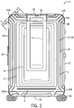
- Figs. 1-3 disclose a plurality of grooves 38 forming a substantially nested quadrilateral patterned outer layer 6.
- the substantially nested quadrilateral pattern of the grooves 38 may be configured to substantially strengthen the structure of the shell 4, and to absorb energy from an impact force by dispersing through resilient deformation between the grooves 38. In this way, the shock energy is dissipated through at least the portion of the shell 4 where the grooves 38 are formed.
- the grooves 38 are configured to reduce the likelihood of permanent deformation of the corner regions 24 by increasing both the strength and absorption properties of the corner regions 24.
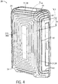
- the grooves 38 may extend and/or loop from the split line 26, over a side 10, 12, 16, 18, 20, 22 of the luggage case 2, and back to the split line 26.
- the grooves 38 may extend from a portion of the split line 26 adjacent one corner region 24 (e.g., a first corner region 24), over a portion of a major face 8 (e.g., the front side 10), and back to the split line 26 spaced away from the first corner region 24.
- the grooves 38 may loop from one corner region 24 to an adjacent corner region 24.
- the grooves 38 may loop from inside one corner region 24 to inside an adjacent corner region 24.
- the grooves 38 extend at least partially across at least one of the sides 10, 12, 16, 18, 20, 22 and extend between and connect two adjacent corner regions 24 to increase the strength of the corner regions 24 and disperse the impact force away from the corner regions 24.
- the grooves 38 may connect two upper corner regions 24A, two lower corner regions 24B, and/or an upper corner region 24A with a lower corner region 24B on the same side.
- the grooves 38 are positioned adjacent the corner regions 24, extend at least partially across at least one of the various sides 10, 12, 16, 18, 20, 22, and are spaced away from one another in a substantially parallel manner.
- Each groove 38 may generally extend along a similar curve as its adjacent groove 38. For example, as shown at least in Fig.
- a plurality of grooves 38 may extend parallel to each other in connecting two adjacent corner regions 24. In other examples, however, the curvature of each individual groove 38 may be different from its adjacent groove 38 (on either side).
- additional grooves 38 may extend for their lengths L across one of the sides 10, 12, 16, 18, 20, 22.
- the additional grooves 38 may be a closed loop formed on one side of the luggage case 2 (e.g., the front side 10). For example, as shown in Figs. 1-3 , grooves 38 may loop around on themselves in substantially a quadrilateral shape on a major face 8 (front or rear sides 10, 12) of the luggage case 2.
- a plurality of successively stepped grooves 38 may be formed by the outer layer 6 on the major face 8 to form a substantially nested quadrilateral pattern.
- the successively stepped looped grooves 38 provide flexibility in a direction normal to the major face 8.
- the grooves 38 are considered to be closed loop despite intervening structure (e.g., the pull handle 36) interrupting the groove 38.
- an individual groove 38 may include a first portion 40, a second portion 42, and a third portion 44.
- the first portion 40 may by positioned on the peripheral wall 14 adjacent a first corner region 24 and extend at an angle relative to the second portion 42.
- the third portion 44 may by positioned on the peripheral wall 14 adjacent a second corner region 24 and extends at an angle relative to the second portion 42.
- the second portion 42 may extend between the first portion 40 and the third portion 44, and in some embodiments may extend substantially parallel or at an angle relative to a major face 8 and/or the split line 26. In some embodiments, at least a portion of the second portion 42 may extend over a major face 8 (e.g., the front side 10) of the luggage case 2.
- the first and third portions 40, 44 may extend at substantially right angles relative to the second portion 42.
- the first and third portions 40, 44 may extend at substantially right angles relative to the split line 26, and the second portion 42 may extend substantially parallel to the split line 26.
- an individual groove 38 may extend inward a depth Y from a nominal surface 48 of the outer layer 6.
- each individual groove 38 also defines a width dimension Z and a length (or extension) dimension L.
- the depth Y is measured in a direction extending into the luggage case 2 from the nominal surface 48 to the bottom of the groove 38.
- the width dimension Z is measured from the top of the groove 38 on one side to the top of the groove 38 on the other side.
- the length dimension L is measured along the generally longitudinal direction along which the groove 38 extends.
- the width and depth Z, Y of a groove 38 may vary along its length L, and may be the same as, or different from, adjacent grooves 38.
- the grooves 38 may be positioned in a manner to have a higher density in and around one or more corner regions 24 of the luggage article, and also may be formed to occur in a lower density with distance away from the corner regions 24. Density in this instance includes the number of grooves per linear unit of measure.
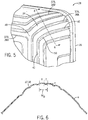
- the transitions between the grooves 38 and the nominal surface 48 may be angular as shown in Fig. 6 , which aids in the resilience and flexibility of the grooves 38 in response to an impact force. In some examples, however, the transitions between the grooves 38 and the nominal surface 48 may be smooth, which may generally increase the stiffness of the grooves 38 in response to an impact force.
- the description below associated with Fig. 6 details the measurement of the depth Y and the width Z, and relative changes thereto, for the groove 38.
- the proportion of the width Z of the grooves 38 may change along the length L; while an overall width W O (made up of the width Z of the groove 38 and a distance X between adjacent grooves 38) of the grooves 38 may stay relatively consistent along the length L.
- the width Z may increase and the distance X may proportionally decrease to maintain the overall width W O relatively consistent along the length L.
- the overall width W O of the grooves 38 may vary along the length L of the grooves 38, and may be the same as, or different from, the adjacent grooves 38.
- the deeper the depth Y and the smaller the width Z of a groove 38 i.e., allowing a higher density of grooves
- the smaller the depth Y and the larger the width dimension Z i.e., the smaller the density of the groove 38
- the less absorptive and resilient the groove 38 and the weaker the corner region 24 may be implemented.
- the number of grooves 38 may be kept constant among shell portions 28, 29 of various sizes.
- the width Z of the grooves 38 may change to accommodate differently sized shell portions 28, 29.
- the depth and width dimensions Y, Z of the grooves 38 may vary along the length L of the grooves 38 to dissipate shock energy throughout the shell portions 28, 29 and prevent permanent deformation.
- the grooves 38 positioned adjacent the corner regions 24 may have a narrower width dimension Z and a deeper depth Y, and thus are more densely positioned.
- the depth Y of the groove 38 may generally decrease, and/or the width dimension Z of the groove 38 may generally increase.
- the distance X between adjacent grooves 38 may be smaller near the corner regions 24 and greater with distance away from the corner regions 24.
- grooves 38 dissipating as they extend away from the corner regions 24.
- More densely-spaced grooves 38 provide a generally greater resilience to impact forces near the corner regions 24 where needed, and create less likelihood of permanent deformation.
- the grooves 38 may be less densely packed at locations spaced away from the corner regions 24 because the impact force has been dissipated or attenuated by the time it reaches these more remote regions and less resilience is needed and/or greater flexibility is desired.
- the grooves 38 may gradually disappear entirely within the interior field of the sides 10, 12, 16, 18, 20, 22 with distance away from the corner regions 24.
- the depth Y of the grooves 38 within the interior field of the sides 10, 12, 16, 18, 20, 22 may be between about 0 percent and about 50 percent, preferably between about 20 percent and about 30 percent and more preferably about 25 percent, compared to the depth Y of the grooves 38 adjacent the corner regions 24. In some embodiments, the depth Y of the grooves 38 within the interior field of the sides 10, 12, 16, 18, 20, 22 is held constant, for example, at about 0.5 mm. In some embodiments, the sides 10, 12, 16, 18, 20, 22 may be relatively flexible compared to the stiffer corner regions 24, which allows the luggage case 2 to pass a corner drop test without using supplemental shell reinforcement. Though the depth Y of the grooves 38 within the interior field of the sides 10, 12, 16, 18, 20, 22 may be about 0 percent for maximum relative corner strength, some depth Y may be necessary for the overall stability of the luggage case 2.
- the depth Y of the grooves 38 may depend on any one or more of the following: the depth of the shell portion 28 or 29, the thickness of the shell portion 28 or 29, the distance X between adjacent grooves 38, the number of grooves 38, anticipated loading of the luggage case 2, the dimensions of the luggage case 2 (e.g., height, width, etc.), and the width Z of the grooves 38, among other factors. For example, the deeper and thicker the shell portion 28 or 29, the greater the depth Y of the grooves 38. Additionally or alternatively, the larger the luggage case 2 in either its width or height dimension, the greater the depth Y of the grooves 38.
- the greater the width Z of the grooves 38 and/or anticipated loading of the luggage case 2 the greater the depth Y of the grooves 38.
- the less number of grooves 38 the greater the depth Y, all else being equal.
- the depth Y of the grooves 38 is approximately equal to the material thickness of the shell portion 28 or 29. Additionally or alternatively, the depth Y of the grooves 38 may be greater than the material thickness of the shell portion 28 or 29. In some embodiments, the depth Y may vary between about 20 percent and about 67 percent of the width Z of the grooves 38 (e.g., about 37.5 percent) depending on the particular application.
- the depth Y of a groove 38 may vary between 2 mm and 4 mm, and the width Z of the groove 38 may vary between 6 mm and 10 mm.
- the depth Y of the grooves 38 is 3 mm, and the width Z of the grooves 38 is 8 mm.
- These values may be proportionally scaled with any one or more of the following: the depth of the shell portion 28 or 29, the dimensions of the luggage case 2, the sheet thickness, the number of grooves 38, anticipated loading, as well as with the distance X between adjacent grooves 38.
- Table 1 below illustrates non-limiting examples of these values scaled with the depth of the shell portion 28 or 29.
- the corresponding case size i.e., height
- sheet thickness i.e., sheet thickness
- anticipated loading are also provided in Table 1 below.
- the numbers are approximate and small variations (i.e., ⁇ 10 percent) are contemplated.
- Table 1 Examples of Groove Width and Depth Dimensions Depth of Shell Portion 28 or 29 (mm) Case Size (cm) Sheet Thickness (mm) Test Load (kg) Preferable Width Z (mm) More preferable Width Z (mm) Preferable Depth Y (mm) More preferable Depth Y (mm) 1 200 55 1.7 10 4.1 - 6.8 5.4 1.4 - 2.7 2.0 2 265 69 1.9 20 5.7 - 9.5 7.6 1.9 - 3.8 2.8 3 280 75 2.0 22 6 - 10 8 2 - 4 3 4 295 81 2.1 25 6.3 - 10.5 8.4 2.1 - 4.2 3.2
- the maximum value for the depth Y of the grooves 38 may be limited to about 50 percent of the width dimension Z. Deeper grooves may locally compromise the wall thickness of the shell portions 28, 29, thereby making the shell portions 28, 29 in that area insufficiently strong and/or insufficiently resilient.
- the additional strength (in percentage) provided to the shell portions 28, 29 (e.g., to the corner regions 24) by the grooves 38 relative to the depth Y of the grooves 38 may generally fall on a bell curve (note the width Z of the grooves 38 is held constant). As illustrated in Fig.
- the grooves 38 when the depth Y of the grooves 38 start decreasing along the length L of the grooves 38 within the interior field of the luggage case 2 may depend on the depth of the shell portion 28 or 29.
- the grooves 38 may be deeper within a circular area A having a diameter and centered substantially at the apex region and encompassing at least a portion of the corner regions 24.
- the depths Y of the grooves 38 may transition from deeper to shallower within the circular area A.
- the depths Y of the grooves may transition from deeper to shallower with distance away from the center of the circular area A to the edge of the circular area A.
- the depths Y of the grooves may transition from 4 mm at the center of the circular area A to 2 mm at the edge of the circular area A.
- the circular area A may generally define a plane that extends generally tangentially from the corner regions 24 at an angle ⁇ relative to the sides 10, 12, 16, 18, 20, 22 of the luggage case 2.
- the plane defined by the circular area A extends at a 45 degree angle relative to the front, top, and right sides 10, 16, 20.
- the depths of the grooves 38 may decrease with distance B away from the circular area A.
- the diameter of the circular area A encompassing deep grooves 38 may be in a range of 80 mm to 150 mm, with an optimal diameter of 110 mm.
- the depths of the grooves 38 may decrease over a distance B in a range of 20 mm to 80 mm, with an optimal distance B of 40 mm.
- the depths of the grooves 38 may fade out completely with distance B away from the circular area A.
- a first groove 38A extends for at least a first portion 40 of its length L 1 substantially perpendicular to the split line 26 and adjacent to a first corner region 24.
- the first groove 38A also extends for at least a second portion 42 of its length L 1 substantially parallel to the split line 26 at least partially across at least one of the sides 10, 12, 16, 18, 20, 22 at a first distance spaced away from the split line 26.
- the first groove 38A also extends for at least a third portion 44 of its length L 1 substantially perpendicular to the split line 26 and adjacent to a second corner region 24 adjacent the first corner region 24. As such, the first groove 38A extends from a first corner region 24 to an adjacent second corner region 24 in a substantially looped manner. Similar to the first groove 38A, a second groove 38B extends for at least a first portion 40 of its length L 2 substantially perpendicular to the split line 26 and adjacent to the first corner region 24. The second groove 38B also extends for at least a second portion 42 of its length L 2 substantially parallel to the split line 26 at least partially across at least one of the sides 10, 12, 16, 18, 20, 22 at a second distance spaced away from the split line 26.
- the second groove 38B also extends for at least a third portion 44 of its length L 2 substantially perpendicular to the split line 26 and adjacent to the second corner region 24.
- the first and second grooves 38A, 38B may begin and terminate adjacent to, and may interconnect, respective adjacent corner regions 24.
- the grooves 38 may also form a partial loop by extending from one corner region 24 for at least a first portion of its length L substantially perpendicular to the split line 26 and adjacent to the first corner region 24 and also extends for at least a second portion of its length L substantially parallel to the split line 26. However, the groove does not make a complete loop to an adjacent corner region 24.
- a third groove 38C may be configured similarly to the first and second grooves 38A, 38B.
- a fourth groove 38D may by formed by the outer layer 6 having a fourth length L 4 .
- the fourth groove 38D may extend for its length L 4 across only one of the sides 10, 12, 16, 18, 20, 22.
- the fourth groove 38D may be a closed loop positioned on a major face 8 (defined as either the front or rear side 10, 12) of the shell 4 and may be configured substantially in a quadrilateral shape.
- a plurality of subsequently stepped grooves 38D may be formed on the major faces 8 to provide flexibility and resilient deformation of the major faces 8.
- the first, second, third, and fourth grooves 38A, 38B, 38C, 38D may or may not be adjacent one another. Also, the first, second, and third grooves 38A, 38B, 38C may extend for their respective lengths L 1 , L 2 , L 3 across one of the sides 10, 12, 16, 18, 20, 22.
- the first groove 38A has a deeper depth Y and a smaller width dimension Z than the second groove 38B
- the second groove 38B has a deeper depth Y and a smaller width dimension Z than the third groove 38C, and so on.
- the first distance from the split line 26 may be greater than the second distance from the split line 26, and the third distance from the split line 26 may be less than both the second distance and the first distance.
- each of the second portions 42 of the respective grooves 38 may run parallel to the edges formed between two of the various sides 10, 12, 16, 18, 20, 22.
- the shell portions 28, 29 may contain at least one groove 38 interconnecting two adjacent corner regions 24 to provide sufficient corner strength and prevent permanent deformation of the corner regions 24.
- the shell portions 28, 29 may include any number of grooves 38 limited only by the size and dimensions of the particular luggage case 2.
- the shell portions 28, 29 may include three grooves 38 interconnecting adjacent corner regions 24, seven closed-loop grooves 38 disposed on the front side 10 of the shell portion 28, and four closed-loop grooves 38 disposed on the rear side 12 of the shell portion 29.
- six grooves 38 may be adjacent each corner region 24, with three of the six grooves 38 extending towards an adjacent corner region 24 and the other three grooves 38 extending towards another adjacent corner region 24.
- Individual grooves 38 may extend differently relative to adjacent grooves 38 with respect to a corner region 24. For example, some grooves 38 may extend from an upper corner region 24A to an adjacent lower corner region 24B, while other grooves 38 may extend from the same upper corner region 24A to an adjacent upper corner region 24A or an adjacent lower corner region 24B.
- the extension of the grooves 38 relative to the corner region 24 affects the absorptive and resilience characteristics of the grooves 38.
- grooves 38 may extend on each side 10, 12, 16, 18, 20, 22 of the luggage case 2.
- each corner region 24 may be connected to an adjacent corner region 24 via a groove 38.
- grooves 38 may extend across only the top, left, and right sides 16, 22, 20 of the luggage case 2.
- the first groove 38A may have a first length L 1
- the second groove 38B may have a second length L 2 , and so on.
- the first length L 1 may be greater than the second length L 2 .
- the respective lengths L 1 , L 2 of the grooves 38A, 38B may each define a coextensive 3-D curve.
- intermediate segments 50 may transition the first, second, and third portions 40, 42, 44 of an individual groove 38 together.
- intermediate segments 50 may transition the first portion 40 to the second portion 42 and the second portion 42 to the third portion 44.
- the intermediate segments 50 may extend for at least portions of their lengths at an angle relative to the corner regions 24 and at an angle relative to the second portions 42.
- the intermediate segments 50 may extend at 45 degree angles relative to the corner regions 24 and 135 degree angles relative to the second portions 42 when viewed from the front side 10 or the rear side 12.
- the top side 16 and the right side 20 may define a substantially right angle at an upper corner region 24A.
- the intermediate segments 50 may bisect the right angle defined by the top side 16 and the right side 20, thereby extending for at least a portion of their lengths at substantially 45 degree angles relative to the top side 16 and the right side 20.
- the intermediate segments 50 and the second portions 42 of two grooves 38 looping from a common corner region 24 to diagonally opposite corner regions 24 on the same side, together with a closed-looped third groove 38C positioned on a major face 8 may define a substantially Y-shaped nominal surface 48 adjacent the common corner region 24.
- each of the grooves 38 may extend a depth Y inward from the nominal surface 48 of the shell 4.
- the depth Y of the first groove 38A may be deeper than the depth Y of the second groove 38B.
- the depth Y of the second groove 38B may be deeper than the depth Y of the third groove 38C.
- the width Z of the grooves 38 may vary to disperse impact force energy throughout portions of the luggage case 2.
- the first groove 38A may have a first width Z 1
- the second groove 38B may have a second width Z 2
- the third groove 38C if included, may have a third width Z 3 , and so on.
- the third width Z 3 may be greater than the second width Z 2
- the second width Z 2 may be greater than the first width Z 1 .
- the respective widths Z 1 , Z 2 , Z 3 of the first, second, and third grooves 38A, 38B, 38C may increase as the distance from the corner regions 24 increases.
- the widths Z of the grooves 38 may be relatively narrower near the corner regions 24 and relatively wide with distance away from the corner regions 24.
- the widths Z of the grooves 38 may alternate from narrower to wider.
- the angle of incidence of the impact force on the corner region 24 may vary widely. It will almost always result in compressive forces being applied in component vectors in the plane of the sides 10, 12, 16, 18, 20, 22 of the luggage case 2. The impact force will also result in bending loads due to component force vectors out of the plane of the luggage case sides 10, 12, 16, 18, 20, 22.
- the grooves 38 described herein improve corner region impact performance by enhancing the absorption of both the compressive and bending forces.
- the deep grooves 38 near the corner regions 24 may concertina in a direction substantially perpendicular to the grooves 38 with the grooves 38 closing up together under impact.
- the grooves 38 may resiliently deform (e.g., concertina) under load to absorb impact energy by allowing the grooves 38 to at least partially close under impact.
- This "concertina effect" of the grooves 38 permits the shell 4 to deflect as a whole but not permanently deform.
- the shallower grooves 38 positioned away from the corner regions 24 may also flex, thereby further absorbing impact energy within the interior field of the luggage case 2.
- the grooves 38 also provide improved strength of the shell 4 by increasing the shell's resistance to bending forces.
- an individual groove 38 may extend at least partially at substantially right angles relative to the split line 26 in first and third portions 40, 44 adjacent the first and second corner regions 24, respectively, and at least partially in a substantially parallel relationship with the split line 26 in a second portion 42. Notwithstanding, the grooves 38 may deviate somewhat from the preferred orientation while still being sufficiently absorptive of the impact force. In some embodiments, the grooves 38 may extend at substantially any angle relative the split line 26 in their first and third portions 40, 44 adjacent the split line 26. For example, the first and third portions 40, 44 may generally extend from the split line 26 and towards each other.
- first and third portions 40, 44 may generally extend from the split line 26 and away from each other.
- the first groove 38A may be oriented differently than the second groove 38B relative the split line 26.
- the grooves 38 may curve relative to the split line 26 in their respective second portions 42.
- the second portions 42 of the grooves 38 may curve concave toward, convex away, or in opposite directions relative to the split line 26.
- the second portion 42 of the first groove 38A may curve differently than the second portion 42 of the second groove 38B relative to the split line 26. This permitted variation allows for designing curvature into the grooves 38 to facilitate a wider variety of impact force angles, as well as permitting flexibility in the resulting aesthetic appearance the grooves 38 have on the overall luggage case 2.
- the grooves 38 described herein may be advantageously implemented on other types of luggage.
- the present disclosure may be implemented as a single shell portion 28 without wheels 30.
- the single shell portion 28 may also be implemented as part of non-wheeled or two-wheeled upright cases with or without handles, or other types of luggage.
- the single shell portion 28 may be oriented substantially vertical when implemented as part of one type of luggage, or the single shell portion 28 may be oriented substantially horizontal when implemented as part of a different type of luggage.
- the groove 38 may be more generally referred to as a surface feature 37, which may also be a ridge, or a combination of a groove and a ridge.
- a surface feature 37 which may also be a ridge, or a combination of a groove and a ridge.
- each individual surface feature 37 whether a groove, a ridge, or a combination of a groove and a ridge, may be configured as described above with reference to a groove 38.
Landscapes
- Chemical & Material Sciences (AREA)
- Engineering & Computer Science (AREA)
- Materials Engineering (AREA)
- Purses, Travelling Bags, Baskets, Or Suitcases (AREA)
Claims (14)
- Valise (2) comprenant:une coque (4) au moins partiellement formée par une couche extérieure (6), et comprenant des première et seconde parties de coque (28, 29) formées au moins partiellement par la couche extérieure et sélectivement fixées ensemble au niveau d'une ligne de division (26), la première partie de coque définissant une première région de coin (24) et une seconde région de coin adjacente (24) et un côté (16, 18, 20) d'une paroi périphérique s'étendant entre lesdites première et deuxième régions de coin; etau moins un premier élément de surface (38A) formé par la couche extérieure, l'au moins un premier élément de surface ayant une longueur et comprenant des première, deuxième et troisième parties (40, 42, 44), où:la première partie s'étend selon un angle par rapport à la deuxième partie, et la troisième partie s'étend selon un angle par rapport à la deuxième partie;la première partie est positionnée sur ledit côté de la paroi périphérique (14) à proximité de la première région de coin et s'étend depuis une partie de la ligne de division;la troisième partie est positionnée sur ledit côté de la paroi périphérique à proximité de la deuxième région de coin et s'étend depuis une partie de la ligne de division; etla deuxième partie s'étend entre la première partie et la troisième partie;la valise comprenant en outre au moins un deuxième élément de surface (37B) formé par la couche extérieure, l'au moins un deuxième élément de surface ayant une longueur et comprenant des première, deuxième et troisième parties (40, 42, 44), où:la première partie de l'au moins un deuxième élément de surface s'étend selon un angle par rapport à la deuxième partie de l'au moins un deuxième élément de surface, et la troisième partie de l'au moins un deuxième élément de surface s'étend selon un angle par rapport à la deuxième partie de l'au moins un deuxième élément de surface;la première partie de l'au moins un deuxième élément de surface est positionnée sur ledit côté de la paroi périphérique à proximité de la première région de coin et s'étend depuis la partie de la ligne de division;la troisième partie de l'au moins un deuxième élément de surface est positionnée sur ledit côté de la paroi périphérique (14) à proximité de la deuxième région de coin et s'étend depuis la partie de la ligne de division; etla deuxième partie de l'au moins un deuxième élément de surface s'étend entre la première partie et la troisième partie de l'au moins un deuxième élément de surface.
- Valise (2) selon la revendication 1, dans laquelle:l'au moins un premier élément de surface ayant une profondeur, dans laquelle;plus on se rapproche de la première région de coin, plus la profondeur de l'au moins un premier élément de surface est grande; etla profondeur de l'au moins un premier élément de surface diminue avec la distance s'éloignant de la première région de coin.
- Valise selon la revendication 1, dans laquelle la première partie de coque définit une troisième région de coin (24) à proximité de la première région de coin et diagonalement opposée à la deuxième région de coin, la valise comprenant en outre au moins un deuxième élément de surface supplémentaire (37B) formé par la couche extérieure, l'au moins un deuxième élément de surface supplémentaire ayant une longueur et comprenant des première, deuxième et troisième parties (40, 42, 44), dans laquelle;
la première partie de l'au moins un deuxième élément de surface supplémentaire s'étend selon un angle par rapport à la deuxième partie de l'au moins un deuxième élément de surface supplémentaire, et la troisième partie de l'au moins un deuxième élément de surface supplémentaire s'étend selon un angle par rapport à la deuxième partie de l'au moins un deuxième élément de surface supplémentaire;
la première partie de l'au moins un deuxième élément de surface supplémentaire est positionnée sur la paroi périphérique à proximité de la première région de coin et s'étend depuis la partie de la ligne de division,
la troisième partie de l'au moins un deuxième élément de surface supplémentaire est positionnée sur la paroi périphérique (14) à proximité de la troisième région de coin et s'étend depuis la partie de la ligne de division, et
la deuxième partie de l'au moins un deuxième élément de surface supplémentaire s'étend entre la première partie et la troisième partie de l'au moins un deuxième élément de surface supplémentaire. - Valise selon la revendication 2, dans laquelle:l'au moins un deuxième élément de surface a une profondeur; etla profondeur de l'au moins un premier élément de surface ou de l'au moins un deuxième élément de surface positionné plus loin de la plus proche des régions de coin est inférieure à la profondeur de l'autre élément de surface positionné plus près de la plus proche des régions de coin.
- Valise selon la revendication 1, dans laquelle:
la profondeur de l'au moins un premier élément de surface comprend une première profondeur au moins partiellement dans la première partie, une deuxième profondeur au moins partiellement dans la deuxième partie, et une troisième profondeur au moins partiellement dans la troisième partie. - Valise selon la revendication 5, dans laquelle la première profondeur et la troisième profondeur sont supérieures à la deuxième profondeur.
- Valise selon l'une des revendications 4 ou 5, dans laquelle:l'au moins un premier élément de surface a une largeur;l'au moins un deuxième élément de surface a une largeur; etla largeur de l'au moins un premier élément de surface ou de l'au moins un deuxième élément de surface positionné plus loin de la plus proche des régions de coin est supérieure à la largeur de l'autre élément de surface positionné plus près de la plus proche des régions de coin; oudans laquelle au moins des parties de l'un des premiers éléments de surface et au moins des parties de l'un des deuxièmes éléments de surface s'étendent sensiblement à des angles sensiblement droits par rapport à la ligne de division.
- Valise selon l'une quelconque des revendications précédentes, comprenant en outre au moins un troisième élément de surface (37D) formé par la couche extérieure, dans laquelle ledit au moins un troisième élément de surface est positionné sur un côté (10, 16, 20) de la valise et forme une boucle fermée.
- Valise selon la revendication 8, dans laquelle l'au moins un premier élément de surface, l'au moins un deuxième élément de surface et l'au moins un troisième élément de surface définissent une surface nominale (48) sensiblement en forme de Y adjacente à la première région de coin.
- Valise selon l'une quelconque des revendications 4 ou 5, dans laquelle une partie de l'un des premiers éléments de surface ou une partie de l'un des deuxièmes éléments de surface s'étend sensiblement selon un angle de 45 degrés par rapport à la première région de coin; ou dans laquelle
une partie de l'au moins un premier élément de surface et une partie de l'au moins un deuxième élément de surface s'étendent sensiblement parallèlement l'une à l'autre, ou s'étendent sensiblement parallèlement à un bord formé par l'intersection d'une face principale (8) et d'un côté adjacent (10, 16, 20) de la valise; ou dans laquelle:la première partie de l'au moins un premier élément de surface s'étend sensiblement à angle droit par rapport à la deuxième partie de l'au moins un premier élément de surface; etla troisième partie de l'au moins un premier élément de surface s'étend sensiblement à angle droit par rapport à la deuxième partie de l'au moins un premier élément de surface. - Valise selon l'une quelconque des revendications précédentes, dans laquelle:l'au moins un premier élément de surface a une largeur; etla profondeur de l'au moins un premier élément de surface se situe entre environ 20 pour cent et environ 67 pour cent, et de préférence environ 38 pour cent, de la largeur de l'au moins un premier élément de surface; oudans laquelle la profondeur de l'au moins un premier élément de surface est comprise entre environ 0 pour cent et environ 50 pour cent, de préférence entre environ 20 pour cent et environ 30 pour cent, et plus préférablement environ 25 pour cent, de la largeur de l'au moins un premier élément de surface à proximité de la première région de coin.
- Valise selon l'une quelconque des revendications précédentes, dans laquelle:la coque comprend une face principale (8), l'au moins un premier élément de surface s'étendant au moins partiellement dans la face principale;la profondeur de l'au moins un premier élément de surface dans la face principale est inférieure à la profondeur de l'au moins un premier élément de surface adjacent à la première région de coin; etla profondeur de l'au moins un premier élément de surface dans la face principale est de préférence d'environ 0,5 mm.
- Valise selon l'une quelconque des revendications précédentes, dans laquelle la profondeur de l'au moins une première surface adjacente à la première région de coin est comprise entre environ 1 mm et environ 4 mm, et de préférence entre environ 2 mm et environ 3,2 mm.
- Valise selon l'une quelconque des revendications précédentes, dans laquelle:l'au moins un premier élément de surface a une largeur; etla largeur de l'au moins un premier élément de surface est comprise entre environ 4 mm et environ 10 mm, et de préférence entre environ 5,5 mm et environ 8,5 mm.
Applications Claiming Priority (2)
| Application Number | Priority Date | Filing Date | Title |
|---|---|---|---|
| EP14192902 | 2014-11-12 | ||
| PCT/EP2015/076487 WO2016075265A1 (fr) | 2014-11-12 | 2015-11-12 | Valise comprenant des éléments de surface fournissant une meilleure résistance |
Publications (2)
| Publication Number | Publication Date |
|---|---|
| EP3217832A1 EP3217832A1 (fr) | 2017-09-20 |
| EP3217832B1 true EP3217832B1 (fr) | 2019-10-02 |
Family
ID=51897161
Family Applications (1)
| Application Number | Title | Priority Date | Filing Date |
|---|---|---|---|
| EP15793856.4A Active EP3217832B1 (fr) | 2014-11-12 | 2015-11-12 | Valise présentant des caractéristiques de surface offrant une meilleure résistance |
Country Status (7)
| Country | Link |
|---|---|
| US (1) | US10292470B2 (fr) |
| EP (1) | EP3217832B1 (fr) |
| JP (1) | JP2017533777A (fr) |
| KR (1) | KR102377910B1 (fr) |
| CN (2) | CN107105843B (fr) |
| AU (1) | AU2015345095B2 (fr) |
| WO (1) | WO2016075265A1 (fr) |
Families Citing this family (25)
| Publication number | Priority date | Publication date | Assignee | Title |
|---|---|---|---|---|
| EP3015018B1 (fr) * | 2014-10-28 | 2019-03-13 | Samsonite IP Holdings S.a.r.l. | Valise présentant des caractéristiques de surface offrant une meilleure résistance dans les angles |
| EP3217832B1 (fr) | 2014-11-12 | 2019-10-02 | Samsonite IP Holdings S.à.r.l. | Valise présentant des caractéristiques de surface offrant une meilleure résistance |
| USD816335S1 (en) * | 2017-02-20 | 2018-05-01 | Solite International Co., Ltd. | Luggage case |
| USD872474S1 (en) * | 2018-03-04 | 2020-01-14 | Thomas Mendoza International Co., Ltd. | Travel case |
| USD889836S1 (en) * | 2018-03-22 | 2020-07-14 | Horizn Studios GmbH | Luggage shell with surface configuration |
| US20230329402A1 (en) * | 2018-08-10 | 2023-10-19 | Louis Vuitton Malletier | Method for producing a rigid shell for luggage, shell for luggage and luggage |
| EP3833210A1 (fr) * | 2018-08-10 | 2021-06-16 | Louis Vuitton Malletier | Procédé pour réaliser une coque de bagage rigide, coque de bagage et bagage |
| CN114449917B (zh) * | 2019-07-26 | 2024-09-27 | 里默瓦有限责任公司 | 行李物品 |
| USD936359S1 (en) * | 2019-10-02 | 2021-11-23 | Delsey | Suitcase |
| USD957126S1 (en) * | 2019-10-02 | 2022-07-12 | Delsey | Suitcase |
| CN110664074A (zh) * | 2019-11-05 | 2020-01-10 | 黄山市星河机器人有限公司 | 一种铝合金拉杆箱及其生产方法 |
| CA196327S (en) * | 2019-12-18 | 2022-05-11 | Samsonite Ip Holdings Sarl | Luggage |
| USD977248S1 (en) * | 2020-08-19 | 2023-02-07 | Tumi, Inc. | Luggage |
| KR102528276B1 (ko) * | 2021-10-08 | 2023-05-03 | 임희선 | 이동식 정리함 |
| USD1041164S1 (en) * | 2022-04-01 | 2024-09-10 | Samsonite IP Holdings S.à r.l. | Luggage case |
| USD1056484S1 (en) * | 2022-04-01 | 2025-01-07 | Samsonite Ip Holdings S.A R.L. | Luggage case |
| USD1037660S1 (en) * | 2022-08-26 | 2024-08-06 | Rimowa Gmbh | Case |
| USD1069404S1 (en) * | 2022-12-27 | 2025-04-08 | Delsey | Suitcase |
| USD990879S1 (en) * | 2023-02-08 | 2023-07-04 | Guangzhou Luggex Technology Co. Ltd | Luggage |
| USD990160S1 (en) * | 2023-02-08 | 2023-06-27 | Guangzhou Luggex Technology Co. Ltd | Luggage |
| USD990159S1 (en) * | 2023-02-08 | 2023-06-27 | Guangzhou Luggex Technology Co. Ltd | Luggage |
| USD1078273S1 (en) * | 2023-09-21 | 2025-06-10 | Xiamen Worthfind Co., Ltd. | Luggage suitcase |
| USD1075298S1 (en) * | 2023-11-20 | 2025-05-20 | Jieshou Shanyouda Electronic Commerce Co., LTD | Suitcase |
| USD1080204S1 (en) * | 2024-04-16 | 2025-06-24 | Xiamen Worthfind Co., Ltd. | Luggage suitcase |
| USD1082309S1 (en) * | 2024-06-18 | 2025-07-08 | Xiamen Worthfind Co., Ltd. | Luggage case |
Citations (1)
| Publication number | Priority date | Publication date | Assignee | Title |
|---|---|---|---|---|
| USD633716S1 (en) * | 2009-03-10 | 2011-03-08 | Titan Kofferwerk GmbH | Luggage |
Family Cites Families (39)
| Publication number | Priority date | Publication date | Assignee | Title |
|---|---|---|---|---|
| US1649292A (en) | 1923-09-06 | 1927-11-15 | Draper Mfg Co | Sheet-metal drum |
| US2036276A (en) | 1931-02-20 | 1936-04-07 | American Can Co | Metal shipping container |
| US1987764A (en) | 1933-09-30 | 1935-01-15 | Shaw Walker Co | Sheet metal case |
| US2510643A (en) | 1946-02-01 | 1950-06-06 | Adrian L Long | Plastic suitcase sections having embedded-hinge and meeting-edge gasket |
| US2950792A (en) | 1957-08-28 | 1960-08-30 | Shwayder Bros Inc | Luggage case |
| US3163686A (en) | 1962-04-02 | 1964-12-29 | Pulp Reproduction Company | Art of forming composite plastic devices |
| US3251460A (en) | 1965-03-15 | 1966-05-17 | W D Adam Company Inc | Cushioned package |
| US3313382A (en) | 1965-05-03 | 1967-04-11 | Samsonite Corp | Luggage case |
| US4113095A (en) | 1976-11-26 | 1978-09-12 | Van Dorn Company | Tray-type processed food containers |
| USD299589S (en) | 1985-11-27 | 1989-01-31 | Echolac Co., Ltd. | Luggage |
| GB8600074D0 (en) | 1986-01-03 | 1986-02-12 | Spartan Luggage Co Ltd | Luggage cases |
| US4703519A (en) * | 1986-01-06 | 1987-10-27 | Krenzel Ronald L | Sewn polyolefin and fabric bag and method of making bag |
| US4712657A (en) | 1986-02-12 | 1987-12-15 | Andiamo Inc. | Method and means for sealing a carrying case |
| US4803769A (en) | 1986-12-31 | 1989-02-14 | Gibbs Richard B | Luggage corner construction method |
| USD335220S (en) * | 1991-04-09 | 1993-05-04 | Southern Case, Inc. | Utility case |
| US5228546A (en) * | 1991-05-07 | 1993-07-20 | Chang S J | Soft gusset, hard-paneled luggage and method of manufacture |
| JPH08505542A (ja) * | 1992-10-20 | 1996-06-18 | リモア コッファーファブリーク ゲゼルシャフト ミット ベシュレンクター ハフツング | 金属製スーツケースおよびその製造方法 |
| TW342659U (en) | 1998-04-23 | 1998-10-11 | Yung Ta Hardware & Plastic Co Ltd | Protection structure for corner of suitcase |
| USD429234S (en) | 1999-02-03 | 2000-08-08 | Gtc Properties, Inc. | Clock radio |
| US6131713A (en) | 1999-07-28 | 2000-10-17 | Sher; Yu-Yi | Framework of luggage |
| GB2361692B (en) | 2000-04-28 | 2003-12-03 | Yuh Yi Sher | Luggage frame |
| USD512566S1 (en) | 2003-08-06 | 2005-12-13 | Vertu | Portion of a bag |
| ES2377156T3 (es) * | 2003-10-21 | 2012-03-23 | Landor & Hawa International Limited | Art�?culo de equipaje. |
| DE102004029453A1 (de) | 2004-06-18 | 2006-06-08 | Samsonite Corp., Denver | Verfahren zur Herstellung eines Kunststoffteiles, insbesondere Gepäckstückschale, aus selbstverstärktem thermoplastischen Material, Kunststoffteil, hergestellt aus selbstverstärktem thermoplastischen Material und Vorrichtung zur Herstellung eines Kunststoffteiles, insbesondere Gepäckstückschale |
| JP2009262499A (ja) | 2008-04-28 | 2009-11-12 | Kasai Kogyo Co Ltd | 発泡樹脂成形品並びにその成形方法 |
| USD627162S1 (en) | 2008-07-30 | 2010-11-16 | Brookstone Purchasing, Inc. | Rolling suitcase |
| BRPI0901615B1 (pt) | 2009-05-14 | 2019-08-06 | Brasilata S/A Embalagens Metálicas | Aperfeiçoamento em recipiente em folha metálica |
| US20110127264A1 (en) | 2009-11-30 | 2011-06-02 | Plano Molding Company | Container assembly |
| US20110186396A1 (en) * | 2010-01-29 | 2011-08-04 | Heys (USA), Inc. | Hard-Sided Suitcase Featuring Hard-Sided Pockets |
| CL2010001187S1 (es) | 2010-04-29 | 2011-08-05 | Samsonite Ip Holdings Sarl | Maleta paralelepipédica rectangular de vértices y aristas redondeadas, caras menores trapeciales y manto sinusoidal de la distinta amplitud en caras verticales mayores; la cara posterior, inferior, frontal y superior poseen banda longitudinal continua con resalte central, y en las dos últimas un delgado resalte rectangular arqueado. |
| US20110284334A1 (en) | 2010-05-24 | 2011-11-24 | Chao-Ming Cheng | Suitcase Having A Shock Absorbing Function |
| USD644435S1 (en) | 2010-11-30 | 2011-09-06 | Xinyue Weng | Upright luggage case |
| CN201986882U (zh) * | 2011-03-18 | 2011-09-28 | 黄木荣 | 一种硅胶饭盒 |
| USD665998S1 (en) | 2011-05-03 | 2012-08-28 | Samsonite Ip Holdings S.A.R.L. | Luggage |
| US8752683B2 (en) * | 2011-06-24 | 2014-06-17 | Tumi, Inc. | Lightweight, high-strength luggage |
| CN202698065U (zh) * | 2011-09-18 | 2013-01-30 | 胡泳江 | 便于通过楼梯移动的拉杆旅行箱 |
| USD710608S1 (en) | 2012-11-01 | 2014-08-12 | Samsonite IP Holdings S.ar.l. | Luggage |
| USD710609S1 (en) | 2012-11-14 | 2014-08-12 | Samsonite IP Holdings S.ar.l. | Luggage |
| EP3217832B1 (fr) | 2014-11-12 | 2019-10-02 | Samsonite IP Holdings S.à.r.l. | Valise présentant des caractéristiques de surface offrant une meilleure résistance |
-
2015
- 2015-11-12 EP EP15793856.4A patent/EP3217832B1/fr active Active
- 2015-11-12 WO PCT/EP2015/076487 patent/WO2016075265A1/fr not_active Ceased
- 2015-11-12 CN CN201580061301.8A patent/CN107105843B/zh active Active
- 2015-11-12 US US15/526,548 patent/US10292470B2/en active Active
- 2015-11-12 CN CN201520900727.5U patent/CN205492905U/zh not_active Expired - Fee Related
- 2015-11-12 KR KR1020177014584A patent/KR102377910B1/ko active Active
- 2015-11-12 AU AU2015345095A patent/AU2015345095B2/en not_active Expired - Fee Related
- 2015-11-12 JP JP2017525887A patent/JP2017533777A/ja active Pending
Patent Citations (1)
| Publication number | Priority date | Publication date | Assignee | Title |
|---|---|---|---|---|
| USD633716S1 (en) * | 2009-03-10 | 2011-03-08 | Titan Kofferwerk GmbH | Luggage |
Also Published As
| Publication number | Publication date |
|---|---|
| CN107105843A (zh) | 2017-08-29 |
| EP3217832A1 (fr) | 2017-09-20 |
| AU2015345095A1 (en) | 2017-06-29 |
| WO2016075265A1 (fr) | 2016-05-19 |
| JP2017533777A (ja) | 2017-11-16 |
| CN107105843B (zh) | 2020-01-10 |
| KR20170084125A (ko) | 2017-07-19 |
| AU2015345095B2 (en) | 2020-10-22 |
| US10292470B2 (en) | 2019-05-21 |
| US20170318926A1 (en) | 2017-11-09 |
| CN205492905U (zh) | 2016-08-24 |
| KR102377910B1 (ko) | 2022-03-23 |
Similar Documents
| Publication | Publication Date | Title |
|---|---|---|
| EP3217832B1 (fr) | Valise présentant des caractéristiques de surface offrant une meilleure résistance | |
| US10292469B2 (en) | Luggage case having surface features providing enhanced corner strength | |
| US9549597B2 (en) | Luggage case structure with protruding lower portion | |
| KR100744250B1 (ko) | 합성수지제 용기 | |
| US9357810B2 (en) | Cyclist helmet | |
| US20170042302A1 (en) | Stackable luggage article | |
| ES2758534T3 (es) | Maleta con ruedas | |
| CN103029886B (zh) | 平板电脑的包装盒 | |
| CN206933606U (zh) | 行李箱物品 | |
| US7216763B2 (en) | Impact protection system for carrying case | |
| HK1242143B (en) | Luggage case having surface features providing enhanced strength | |
| HK1242143A1 (en) | Luggage case having surface features providing enhanced strength | |
| US10542803B2 (en) | Case for a mobile device | |
| HK1224155B (en) | Luggage case having surface features providing enhanced corner strength | |
| US20070215427A1 (en) | Luggage side panel | |
| JP3188635U (ja) | ドラム用ケース | |
| JP2004154005A (ja) | ロッド収納ケース | |
| KR20140004840U (ko) | 컴퓨터를 수용하기 위한 구조를 갖는 가방 |
Legal Events
| Date | Code | Title | Description |
|---|---|---|---|
| STAA | Information on the status of an ep patent application or granted ep patent |
Free format text: STATUS: THE INTERNATIONAL PUBLICATION HAS BEEN MADE |
|
| PUAI | Public reference made under article 153(3) epc to a published international application that has entered the european phase |
Free format text: ORIGINAL CODE: 0009012 |
|
| STAA | Information on the status of an ep patent application or granted ep patent |
Free format text: STATUS: REQUEST FOR EXAMINATION WAS MADE |
|
| 17P | Request for examination filed |
Effective date: 20170607 |
|
| AK | Designated contracting states |
Kind code of ref document: A1 Designated state(s): AL AT BE BG CH CY CZ DE DK EE ES FI FR GB GR HR HU IE IS IT LI LT LU LV MC MK MT NL NO PL PT RO RS SE SI SK SM TR |
|
| AX | Request for extension of the european patent |
Extension state: BA ME |
|
| DAV | Request for validation of the european patent (deleted) | ||
| DAX | Request for extension of the european patent (deleted) | ||
| STAA | Information on the status of an ep patent application or granted ep patent |
Free format text: STATUS: EXAMINATION IS IN PROGRESS |
|
| REG | Reference to a national code |
Ref country code: HK Ref legal event code: DE Ref document number: 1242143 Country of ref document: HK |
|
| 17Q | First examination report despatched |
Effective date: 20180607 |
|
| GRAP | Despatch of communication of intention to grant a patent |
Free format text: ORIGINAL CODE: EPIDOSNIGR1 |
|
| STAA | Information on the status of an ep patent application or granted ep patent |
Free format text: STATUS: GRANT OF PATENT IS INTENDED |
|
| INTG | Intention to grant announced |
Effective date: 20190423 |
|
| GRAS | Grant fee paid |
Free format text: ORIGINAL CODE: EPIDOSNIGR3 |
|
| GRAA | (expected) grant |
Free format text: ORIGINAL CODE: 0009210 |
|
| STAA | Information on the status of an ep patent application or granted ep patent |
Free format text: STATUS: THE PATENT HAS BEEN GRANTED |
|
| AK | Designated contracting states |
Kind code of ref document: B1 Designated state(s): AL AT BE BG CH CY CZ DE DK EE ES FI FR GB GR HR HU IE IS IT LI LT LU LV MC MK MT NL NO PL PT RO RS SE SI SK SM TR |
|
| REG | Reference to a national code |
Ref country code: GB Ref legal event code: FG4D |
|
| RIN1 | Information on inventor provided before grant (corrected) |
Inventor name: VANDEMERGEL, MICHAEL Inventor name: SIJMONS, ERIK |
|
| REG | Reference to a national code |
Ref country code: CH Ref legal event code: EP Ref country code: AT Ref legal event code: REF Ref document number: 1185231 Country of ref document: AT Kind code of ref document: T Effective date: 20191015 |
|
| REG | Reference to a national code |
Ref country code: DE Ref legal event code: R096 Ref document number: 602015039153 Country of ref document: DE |
|
| REG | Reference to a national code |
Ref country code: IE Ref legal event code: FG4D |
|
| REG | Reference to a national code |
Ref country code: NL Ref legal event code: MP Effective date: 20191002 |
|
| REG | Reference to a national code |
Ref country code: LT Ref legal event code: MG4D |
|
| REG | Reference to a national code |
Ref country code: AT Ref legal event code: MK05 Ref document number: 1185231 Country of ref document: AT Kind code of ref document: T Effective date: 20191002 |
|
| PG25 | Lapsed in a contracting state [announced via postgrant information from national office to epo] |
Ref country code: SE Free format text: LAPSE BECAUSE OF FAILURE TO SUBMIT A TRANSLATION OF THE DESCRIPTION OR TO PAY THE FEE WITHIN THE PRESCRIBED TIME-LIMIT Effective date: 20191002 Ref country code: LV Free format text: LAPSE BECAUSE OF FAILURE TO SUBMIT A TRANSLATION OF THE DESCRIPTION OR TO PAY THE FEE WITHIN THE PRESCRIBED TIME-LIMIT Effective date: 20191002 Ref country code: NL Free format text: LAPSE BECAUSE OF FAILURE TO SUBMIT A TRANSLATION OF THE DESCRIPTION OR TO PAY THE FEE WITHIN THE PRESCRIBED TIME-LIMIT Effective date: 20191002 Ref country code: ES Free format text: LAPSE BECAUSE OF FAILURE TO SUBMIT A TRANSLATION OF THE DESCRIPTION OR TO PAY THE FEE WITHIN THE PRESCRIBED TIME-LIMIT Effective date: 20191002 Ref country code: LT Free format text: LAPSE BECAUSE OF FAILURE TO SUBMIT A TRANSLATION OF THE DESCRIPTION OR TO PAY THE FEE WITHIN THE PRESCRIBED TIME-LIMIT Effective date: 20191002 Ref country code: AT Free format text: LAPSE BECAUSE OF FAILURE TO SUBMIT A TRANSLATION OF THE DESCRIPTION OR TO PAY THE FEE WITHIN THE PRESCRIBED TIME-LIMIT Effective date: 20191002 Ref country code: PT Free format text: LAPSE BECAUSE OF FAILURE TO SUBMIT A TRANSLATION OF THE DESCRIPTION OR TO PAY THE FEE WITHIN THE PRESCRIBED TIME-LIMIT Effective date: 20200203 Ref country code: BG Free format text: LAPSE BECAUSE OF FAILURE TO SUBMIT A TRANSLATION OF THE DESCRIPTION OR TO PAY THE FEE WITHIN THE PRESCRIBED TIME-LIMIT Effective date: 20200102 Ref country code: FI Free format text: LAPSE BECAUSE OF FAILURE TO SUBMIT A TRANSLATION OF THE DESCRIPTION OR TO PAY THE FEE WITHIN THE PRESCRIBED TIME-LIMIT Effective date: 20191002 Ref country code: PL Free format text: LAPSE BECAUSE OF FAILURE TO SUBMIT A TRANSLATION OF THE DESCRIPTION OR TO PAY THE FEE WITHIN THE PRESCRIBED TIME-LIMIT Effective date: 20191002 Ref country code: GR Free format text: LAPSE BECAUSE OF FAILURE TO SUBMIT A TRANSLATION OF THE DESCRIPTION OR TO PAY THE FEE WITHIN THE PRESCRIBED TIME-LIMIT Effective date: 20200103 Ref country code: NO Free format text: LAPSE BECAUSE OF FAILURE TO SUBMIT A TRANSLATION OF THE DESCRIPTION OR TO PAY THE FEE WITHIN THE PRESCRIBED TIME-LIMIT Effective date: 20200102 |
|
| PG25 | Lapsed in a contracting state [announced via postgrant information from national office to epo] |
Ref country code: CZ Free format text: LAPSE BECAUSE OF FAILURE TO SUBMIT A TRANSLATION OF THE DESCRIPTION OR TO PAY THE FEE WITHIN THE PRESCRIBED TIME-LIMIT Effective date: 20191002 Ref country code: IS Free format text: LAPSE BECAUSE OF FAILURE TO SUBMIT A TRANSLATION OF THE DESCRIPTION OR TO PAY THE FEE WITHIN THE PRESCRIBED TIME-LIMIT Effective date: 20200224 Ref country code: HR Free format text: LAPSE BECAUSE OF FAILURE TO SUBMIT A TRANSLATION OF THE DESCRIPTION OR TO PAY THE FEE WITHIN THE PRESCRIBED TIME-LIMIT Effective date: 20191002 Ref country code: RS Free format text: LAPSE BECAUSE OF FAILURE TO SUBMIT A TRANSLATION OF THE DESCRIPTION OR TO PAY THE FEE WITHIN THE PRESCRIBED TIME-LIMIT Effective date: 20191002 |
|
| PG25 | Lapsed in a contracting state [announced via postgrant information from national office to epo] |
Ref country code: AL Free format text: LAPSE BECAUSE OF FAILURE TO SUBMIT A TRANSLATION OF THE DESCRIPTION OR TO PAY THE FEE WITHIN THE PRESCRIBED TIME-LIMIT Effective date: 20191002 |
|
| REG | Reference to a national code |
Ref country code: CH Ref legal event code: PL |
|
| REG | Reference to a national code |
Ref country code: DE Ref legal event code: R097 Ref document number: 602015039153 Country of ref document: DE |
|
| PG2D | Information on lapse in contracting state deleted |
Ref country code: IS |
|
| PG25 | Lapsed in a contracting state [announced via postgrant information from national office to epo] |
Ref country code: LI Free format text: LAPSE BECAUSE OF NON-PAYMENT OF DUE FEES Effective date: 20191130 Ref country code: MC Free format text: LAPSE BECAUSE OF FAILURE TO SUBMIT A TRANSLATION OF THE DESCRIPTION OR TO PAY THE FEE WITHIN THE PRESCRIBED TIME-LIMIT Effective date: 20191002 Ref country code: CH Free format text: LAPSE BECAUSE OF NON-PAYMENT OF DUE FEES Effective date: 20191130 Ref country code: EE Free format text: LAPSE BECAUSE OF FAILURE TO SUBMIT A TRANSLATION OF THE DESCRIPTION OR TO PAY THE FEE WITHIN THE PRESCRIBED TIME-LIMIT Effective date: 20191002 Ref country code: DK Free format text: LAPSE BECAUSE OF FAILURE TO SUBMIT A TRANSLATION OF THE DESCRIPTION OR TO PAY THE FEE WITHIN THE PRESCRIBED TIME-LIMIT Effective date: 20191002 Ref country code: LU Free format text: LAPSE BECAUSE OF NON-PAYMENT OF DUE FEES Effective date: 20191112 Ref country code: RO Free format text: LAPSE BECAUSE OF FAILURE TO SUBMIT A TRANSLATION OF THE DESCRIPTION OR TO PAY THE FEE WITHIN THE PRESCRIBED TIME-LIMIT Effective date: 20191002 Ref country code: IS Free format text: LAPSE BECAUSE OF FAILURE TO SUBMIT A TRANSLATION OF THE DESCRIPTION OR TO PAY THE FEE WITHIN THE PRESCRIBED TIME-LIMIT Effective date: 20200202 |
|
| PLBE | No opposition filed within time limit |
Free format text: ORIGINAL CODE: 0009261 |
|
| STAA | Information on the status of an ep patent application or granted ep patent |
Free format text: STATUS: NO OPPOSITION FILED WITHIN TIME LIMIT |
|
| REG | Reference to a national code |
Ref country code: BE Ref legal event code: MM Effective date: 20191130 |
|
| PG25 | Lapsed in a contracting state [announced via postgrant information from national office to epo] |
Ref country code: SM Free format text: LAPSE BECAUSE OF FAILURE TO SUBMIT A TRANSLATION OF THE DESCRIPTION OR TO PAY THE FEE WITHIN THE PRESCRIBED TIME-LIMIT Effective date: 20191002 Ref country code: IT Free format text: LAPSE BECAUSE OF FAILURE TO SUBMIT A TRANSLATION OF THE DESCRIPTION OR TO PAY THE FEE WITHIN THE PRESCRIBED TIME-LIMIT Effective date: 20191002 Ref country code: SK Free format text: LAPSE BECAUSE OF FAILURE TO SUBMIT A TRANSLATION OF THE DESCRIPTION OR TO PAY THE FEE WITHIN THE PRESCRIBED TIME-LIMIT Effective date: 20191002 |
|
| 26N | No opposition filed |
Effective date: 20200703 |
|
| PG25 | Lapsed in a contracting state [announced via postgrant information from national office to epo] |
Ref country code: IE Free format text: LAPSE BECAUSE OF NON-PAYMENT OF DUE FEES Effective date: 20191112 |
|
| PG25 | Lapsed in a contracting state [announced via postgrant information from national office to epo] |
Ref country code: BE Free format text: LAPSE BECAUSE OF NON-PAYMENT OF DUE FEES Effective date: 20191130 Ref country code: SI Free format text: LAPSE BECAUSE OF FAILURE TO SUBMIT A TRANSLATION OF THE DESCRIPTION OR TO PAY THE FEE WITHIN THE PRESCRIBED TIME-LIMIT Effective date: 20191002 |
|
| PG25 | Lapsed in a contracting state [announced via postgrant information from national office to epo] |
Ref country code: CY Free format text: LAPSE BECAUSE OF FAILURE TO SUBMIT A TRANSLATION OF THE DESCRIPTION OR TO PAY THE FEE WITHIN THE PRESCRIBED TIME-LIMIT Effective date: 20191002 |
|
| PG25 | Lapsed in a contracting state [announced via postgrant information from national office to epo] |
Ref country code: HU Free format text: LAPSE BECAUSE OF FAILURE TO SUBMIT A TRANSLATION OF THE DESCRIPTION OR TO PAY THE FEE WITHIN THE PRESCRIBED TIME-LIMIT; INVALID AB INITIO Effective date: 20151112 Ref country code: MT Free format text: LAPSE BECAUSE OF FAILURE TO SUBMIT A TRANSLATION OF THE DESCRIPTION OR TO PAY THE FEE WITHIN THE PRESCRIBED TIME-LIMIT Effective date: 20191002 |
|
| PG25 | Lapsed in a contracting state [announced via postgrant information from national office to epo] |
Ref country code: TR Free format text: LAPSE BECAUSE OF FAILURE TO SUBMIT A TRANSLATION OF THE DESCRIPTION OR TO PAY THE FEE WITHIN THE PRESCRIBED TIME-LIMIT Effective date: 20191002 |
|
| PG25 | Lapsed in a contracting state [announced via postgrant information from national office to epo] |
Ref country code: MK Free format text: LAPSE BECAUSE OF FAILURE TO SUBMIT A TRANSLATION OF THE DESCRIPTION OR TO PAY THE FEE WITHIN THE PRESCRIBED TIME-LIMIT Effective date: 20191002 |
|
| P01 | Opt-out of the competence of the unified patent court (upc) registered |
Effective date: 20230528 |
|
| PGFP | Annual fee paid to national office [announced via postgrant information from national office to epo] |
Ref country code: GB Payment date: 20250918 Year of fee payment: 11 |
|
| PGFP | Annual fee paid to national office [announced via postgrant information from national office to epo] |
Ref country code: FR Payment date: 20250922 Year of fee payment: 11 |
|
| PGFP | Annual fee paid to national office [announced via postgrant information from national office to epo] |
Ref country code: DE Payment date: 20250923 Year of fee payment: 11 |