EP3218230B1 - Réseau d'alimentation de vehicule automobile - Google Patents
Réseau d'alimentation de vehicule automobile Download PDFInfo
- Publication number
- EP3218230B1 EP3218230B1 EP15804332.3A EP15804332A EP3218230B1 EP 3218230 B1 EP3218230 B1 EP 3218230B1 EP 15804332 A EP15804332 A EP 15804332A EP 3218230 B1 EP3218230 B1 EP 3218230B1
- Authority
- EP
- European Patent Office
- Prior art keywords
- load
- current path
- motor vehicle
- load current
- power distributor
- Prior art date
- Legal status (The legal status is an assumption and is not a legal conclusion. Google has not performed a legal analysis and makes no representation as to the accuracy of the status listed.)
- Not-in-force
Links
Images

Classifications
-
- B—PERFORMING OPERATIONS; TRANSPORTING
- B60—VEHICLES IN GENERAL
- B60R—VEHICLES, VEHICLE FITTINGS, OR VEHICLE PARTS, NOT OTHERWISE PROVIDED FOR
- B60R16/00—Electric or fluid circuits specially adapted for vehicles and not otherwise provided for; Arrangement of elements of electric or fluid circuits specially adapted for vehicles and not otherwise provided for
- B60R16/02—Electric or fluid circuits specially adapted for vehicles and not otherwise provided for; Arrangement of elements of electric or fluid circuits specially adapted for vehicles and not otherwise provided for electric constitutive elements
- B60R16/03—Electric or fluid circuits specially adapted for vehicles and not otherwise provided for; Arrangement of elements of electric or fluid circuits specially adapted for vehicles and not otherwise provided for electric constitutive elements for supply of electrical power to vehicle subsystems or for
-
- B—PERFORMING OPERATIONS; TRANSPORTING
- B60—VEHICLES IN GENERAL
- B60L—PROPULSION OF ELECTRICALLY-PROPELLED VEHICLES; SUPPLYING ELECTRIC POWER FOR AUXILIARY EQUIPMENT OF ELECTRICALLY-PROPELLED VEHICLES; ELECTRODYNAMIC BRAKE SYSTEMS FOR VEHICLES IN GENERAL; MAGNETIC SUSPENSION OR LEVITATION FOR VEHICLES; MONITORING OPERATING VARIABLES OF ELECTRICALLY-PROPELLED VEHICLES; ELECTRIC SAFETY DEVICES FOR ELECTRICALLY-PROPELLED VEHICLES
- B60L1/00—Supplying electric power to auxiliary equipment of vehicles
-
- B—PERFORMING OPERATIONS; TRANSPORTING
- B60—VEHICLES IN GENERAL
- B60R—VEHICLES, VEHICLE FITTINGS, OR VEHICLE PARTS, NOT OTHERWISE PROVIDED FOR
- B60R16/00—Electric or fluid circuits specially adapted for vehicles and not otherwise provided for; Arrangement of elements of electric or fluid circuits specially adapted for vehicles and not otherwise provided for
- B60R16/005—Electro-mechanical devices, e.g. switched
-
- B—PERFORMING OPERATIONS; TRANSPORTING
- B60—VEHICLES IN GENERAL
- B60R—VEHICLES, VEHICLE FITTINGS, OR VEHICLE PARTS, NOT OTHERWISE PROVIDED FOR
- B60R16/00—Electric or fluid circuits specially adapted for vehicles and not otherwise provided for; Arrangement of elements of electric or fluid circuits specially adapted for vehicles and not otherwise provided for
- B60R16/02—Electric or fluid circuits specially adapted for vehicles and not otherwise provided for; Arrangement of elements of electric or fluid circuits specially adapted for vehicles and not otherwise provided for electric constitutive elements
- B60R16/023—Electric or fluid circuits specially adapted for vehicles and not otherwise provided for; Arrangement of elements of electric or fluid circuits specially adapted for vehicles and not otherwise provided for electric constitutive elements for transmission of signals between vehicle parts or subsystems
- B60R16/0238—Electrical distribution centers
-
- G—PHYSICS
- G01—MEASURING; TESTING
- G01R—MEASURING ELECTRIC VARIABLES; MEASURING MAGNETIC VARIABLES
- G01R31/00—Arrangements for testing electric properties; Arrangements for locating electric faults; Arrangements for electrical testing characterised by what is being tested not provided for elsewhere
- G01R31/005—Testing of electric installations on transport means
- G01R31/006—Testing of electric installations on transport means on road vehicles, e.g. automobiles or trucks
-
- B—PERFORMING OPERATIONS; TRANSPORTING
- B60—VEHICLES IN GENERAL
- B60Y—INDEXING SCHEME RELATING TO ASPECTS CROSS-CUTTING VEHICLE TECHNOLOGY
- B60Y2400/00—Special features of vehicle units
- B60Y2400/30—Sensors
- B60Y2400/308—Electric sensors
- B60Y2400/3084—Electric currents sensors
-
- B—PERFORMING OPERATIONS; TRANSPORTING
- B60—VEHICLES IN GENERAL
- B60Y—INDEXING SCHEME RELATING TO ASPECTS CROSS-CUTTING VEHICLE TECHNOLOGY
- B60Y2400/00—Special features of vehicle units
- B60Y2400/30—Sensors
- B60Y2400/308—Electric sensors
- B60Y2400/3086—Electric voltages sensors
-
- G—PHYSICS
- G01—MEASURING; TESTING
- G01R—MEASURING ELECTRIC VARIABLES; MEASURING MAGNETIC VARIABLES
- G01R31/00—Arrangements for testing electric properties; Arrangements for locating electric faults; Arrangements for electrical testing characterised by what is being tested not provided for elsewhere
- G01R31/50—Testing of electric apparatus, lines, cables or components for short-circuits, continuity, leakage current or incorrect line connections
- G01R31/52—Testing for short-circuits, leakage current or ground faults
Definitions
- the invention relates to a motor vehicle supply network and in particular to a 48V on-board network of a motor vehicle.
- Motor vehicles are currently equipped with a direct current supply network, which is designed as a so-called 12V on-board network and accordingly has one or more 12V voltage sources.
- 12V on-board network since the number of electrical consumers in a motor vehicle has recently increased significantly from vehicle generation to vehicle generation, the 12 V on-board network is not regarded as sustainable.
- arcs are formed, which can lead to a cable fire and consequently to a vehicle fire.
- Corresponding arcs arise, for example, when a cable insulation is at least locally removed by friction on an adjacent component or an adjacent assembly and as a result a conductor of the direct current supply network is then exposed and positioned close to an electrically conductive assembly such as the vehicle frame.
- a potential difference of 15V, for example, between the exposed conductor and the conductive assembly is sufficient and a relatively low power transfer across the exposed conductor of about 50 watts to create an arc between the exposed conductor and the electrically conductive assembly.
- the control device has a power module with a semiconductor switching element. At least one electrical load can be controlled by means of the control module, in particular by means of the semiconductor switching element.
- the control module has a current measuring unit and a voltage measuring unit which, in the event of an overcurrent and / or an overvoltage, electrically bypass the semiconductor switching element to a ground potential and thus divert a potential fault current.
- the WO 97/01103 A1 describes a monitoring unit for a (motor vehicle) battery.
- the monitoring unit is set up and designed in such a way that it is switched off the battery by means of a switch when a critical state occurs.
- a critical condition is, for example, a drop in the state of charge of the battery below a predetermined value.
- the invention is based on the object of specifying an advantageously configured motor vehicle supply network.
- a corresponding motor vehicle supply network is designed in particular for a motor vehicle and is preferably configured as a direct current supply network and in particular as a 48V on-board network (48-volt on-board network). It includes a current or voltage source and a power distributor that is used to Feeding power from the power source is connected to the power source via a feed line current path, the corresponding feed line current path typically being formed at least in sections by a power transmission cable, or cable for short.
- the motor vehicle supply network comprises at least one load, that is to say an electrical consumer, which is connected to the power distributor via a load current path with an integrated semiconductor switch in order to be supplied with power from the power distributor.
- the load current path is also typically formed at least in sections by a cable.
- the power distributor in turn comprises a current measuring unit, a voltage measuring unit and a monitoring unit, which are integrated in the power distributor and are accommodated, for example, in a common housing or on a common printed circuit board.
- the monitoring unit is set up in such a way that it detects an impending incident in the motor vehicle supply network and in particular in the load current path with the at least one load based on the measurement data from the current measurement unit and / or the measurement data from the voltage measurement unit and then switches off the load using the semiconductor switch in the current path initiates at least one load, both impending overcurrent accidents and impending arcing accidents being recognized as impending accidents.
- the motor vehicle supply network presented here is thus protected against various incidents, so that consequential damage resulting therefrom, in particular cable or vehicle fires, is avoided.
- the term accident is not used for the occurrence of an error or defect that disrupts the functionality of the direct current distribution network, but rather for the occurrence of an event or system state which is caused by an error or a defect in the direct current Distribution network and is viewed as potentially problematic or critical.
- a similar differentiation is still made, for example, in the event of a cable break.
- a cable break represents a defect, but is not in itself problematic or critical.
- there may be a flashover in the area of the cable break i.e. the formation of an arc that bridges the break point so that the current flows again through the current path to the connected load. It is precisely this arc that is viewed as potentially problematic or critical, as it can trigger a cable and / or vehicle fire.
- the protection system of the motor vehicle supply network and in particular the monitoring unit in the power distributor is preferably designed in such a way that it responds even before a critical event occurs or a potentially problematic state is reached. In this way, consequential damage in the motor vehicle supply network or in the immediate vicinity is avoided and the occurrence of arcs is prevented.
- impending overcurrent accidents and impending arcing accidents stand for various possible conditions or situations to which the protection system should react, in particular by switching off the at least one load.
- the term impending overcurrent incident stands for an increase in the current strength due to a so-called short circuit, as a result of which Amperage in the affected load current path increases to a multiple of the nominal amperage, so quasi the intended amperage.
- the fastest possible disconnection of the load current path concerned from the energy supply and thus switching off the at least one load is desired and accordingly the monitoring unit is set up, for example, in such a way that the semiconductor switch is opened or the semiconductor switch is blocked in the load current path with the at least one load the monitoring unit is initiated as soon as a value greater than twice the nominal current intensity is measured by the current measuring unit.
- a relatively small excess of the rated current is only assessed and recognized as an impending overcurrent incident if the current in the affected load current path remains above the rated current for a specified period of time.
- the monitoring unit is therefore preferably set up in such a way that it only initiates an opening or blocking of the semiconductor switch in the relevant load current path when the current strength remains above the nominal current strength, for example for at least 10 s. In this way, it is taken into account that fluctuations in the current intensity can in principle occur in a DC voltage supply network, so that the current intensity in a current path of the motor vehicle supply network is temporarily above the actually intended value, i.e. the nominal current intensity.
- the risk of resulting damage to an assembly of the motor vehicle supply network and in particular to the at least one load is to be classified as low and the monitoring unit is accordingly preferably designed in such a way that a brief exceeding of the nominal current strength is tolerated as long as the current strength does not exceed a predetermined limit value, which is regarded as an indication of a short circuit.
- the monitoring unit is accordingly preferably designed in such a way that a brief exceeding of the nominal current strength is tolerated as long as the current strength does not exceed a predetermined limit value, which is regarded as an indication of a short circuit.
- the monitoring unit is designed in such a way that the most diverse, or at least those which are considered to be particularly relevant, in principle possible impending accidents are detected, i.e. recognized without differentiating between the various impending accidents, i.e. without identifying which incident exactly threatens to occur.
- the system reacts accordingly, i.e. in particular the opening or blocking of the semiconductor switch in the current path with the at least one load controls the monitoring unit directly or initiates a corresponding control, for example by transmitting a type of trigger signal to an output stage or amplifier stage which is used to control the semiconductor switch.
- impending arc accident is typically used to refer to various types, some of them in the DE 10 20 12 019 996 A1 described, potentially possible impending accidents are summarized.
- the associated accidents are characterized by the fact that they can lead to the creation or formation of arcs, i.e. in principle to the generation of a plasma.
- arcs are not only undesirable, but also potentially problematic since they can, as explained at the beginning, trigger cable fires or even vehicle fires.
- motor vehicle supply networks are preferably provided with an integrated fuse system presented here, for which a source voltage or mains voltage greater than 20 volts is provided, i.e. in which at least one voltage source with a supply voltage greater than 20 volts is integrated.
- a corresponding configuration for motor vehicle supply networks is also preferably provided, which has at least one current path and in particular one load current path, via which at least at times more than 300 watts and in particular more than 500 watts, for example about 1,000 watts, to supply a load, that is, an electrical consumer.
- the risk of such arcs is not considered to be negligible and accordingly these motor vehicle supply networks are protected not only against overcurrents but also against arcs.
- all or at least the essential functional elements that serve to monitor and thus protect the motor vehicle supply network are preferably part of the power distributor and thus part of a single unit prefabricated for the production of the motor vehicle supply network.
- the functional units provided for protection in the power distributor i.e. a prefabricated unit that is provided anyway
- an additional modular module or an additional prefabricated unit for the functional elements for protecting the motor vehicle supply network can be dispensed with.
- at least the essential functional units i.e. the current measuring unit, the voltage measuring unit and the monitoring unit, are preferably in a common housing, the housing of the power distributor, housed and / or implemented on a common printed circuit board.
- the power distributor is also designed in such a way that the supply line current path in the power distributor splits into several load current paths, with a load being connected to the power distributor via each of these load current paths.
- the electrical power made available by the power source is then distributed to the various connected loads in the power distributor as required, so that each load is supplied with sufficient power when required.
- a separate semiconductor switch is integrated into each load current path and each load current path is monitored for faults.
- a separate current measuring unit and / or a separate voltage measuring unit are also provided for each load current path, with the aid of which load current path-dependent current and voltage measurements are made possible.
- a single monitoring unit is preferably provided for monitoring the corresponding measured values and is accordingly accommodated in the power distributor.
- the monitoring unit is expediently designed in such a way that it not only detects an imminent incident, i.e. an imminent overcurrent incident or an imminent arc incident, but also in which load current path the incident is threatening, in which case only the load of the person concerned Load current path is switched off, in which the opening or blocking of the corresponding semiconductor switch is initiated by the monitoring unit.
- an imminent incident i.e. an imminent overcurrent incident or an imminent arc incident
- load current path the incident is threatening
- the load of the person concerned Load current path is switched off, in which the opening or blocking of the corresponding semiconductor switch is initiated by the monitoring unit.
- the semiconductor switch is designed as a power transistor and in particular as a MOSFET, that is to say as a metal-oxide-semiconductor field effect transistor.
- MOSFETs can easily be used for high powers up to several 100 A and up to about 1,000 V (power MOSFET) and are characterized at the same time by short switching times, which means that such transistors are in principle well suited for implementing circuit breakers or fuse switches to protect a motor vehicle supply network.
- integrated circuits can be built without any problems with the aid of corresponding power transistors or MOSFETs, whereby, for example, semiconductor switches or fuse switches with additional functions can also be produced and used in the motor vehicle supply network.
- the semiconductor switch is not necessarily given by a single transistor, but can also be constructed and constructed in a more complex manner depending on the application. It is therefore advantageous, inter alia, if a current measuring unit is integrated into such a semiconductor switch, which measures the current intensity of the current flowing into a load current path via the semiconductor switch.
- PROFET TM series or product line
- a respective semiconductor switch, a respective current measuring unit, a respective voltage measuring unit and a monitoring unit common for all loads are arranged on a common printed circuit board for each of the loads. All elements for monitoring are therefore compactly integrated on a common printed circuit board, at least in a common component (power distributor). This only needs to be connected to the power source on the input side and has several connections (e.g. plug-in connections) for the individual load paths on the output side.
- the monitoring unit is preferably designed not only to recognize the most varied of imminent accidents, but also what kind of imminent incident it is, that is, which type of incident is threatening to occur. It is further preferred not only to differentiate between impending overcurrent accidents and impending arcing accidents; instead, as a rule, there is a further differentiation, i.e., among other things, a differentiation between an impending overcurrent accident due to a short circuit and an impending overcurrent accident where the amperage is greater than the nominal amperage and less than, for example, twice the nominal amperage over a longer period of time.
- the monitoring unit is also preferably designed to distinguish between different impending arcing incidents, that is to say in particular between an imminent so-called serial arcing incident and an imminent so-called parallel arcing incident.
- an imminent serial arc fault if there is a cable break or wire break in a section of a load current path that is formed by a conductor wire or a cable or the conductivity is significantly reduced at certain points for some other reason.
- the current flow in the area of the cable break or wire break is interrupted or at least greatly reduced, which leads to a charge accumulation and thus to a relatively high potential difference over a relatively short distance.
- an arc then forms which bridges the break point or the defective section, so that in turn current flows quasi serially along the current path to the load.
- the occurrence of the arc is to be equated with the occurrence of the serial arc fault.
- a parallel arc fault if at least part of the current flows through an arc from the load current path into another current path or simply a charge carrier sink.
- a parallel arc fault if at least part of the current flows through an arc from the load current path into another current path or simply a charge carrier sink.
- the monitoring unit is now designed for a differentiation or a differentiated detection of different impending incidents, then this information can be used in different ways. As already written before, it is intended, for example, to design the direct current distribution network in such a way that that different impending incidents also result in different reactions, so that for example the monitoring unit is set up in such a way that it initiates switching off of semiconductor switches depending on the impending incident either immediately after detecting a current value greater than the nominal current value or with a predetermined time delay.
- this information can be transmitted to an external receiver that is not arranged in the power distributor, that is to say, for example, to a control device in the on-board network of the motor vehicle.
- the information is then inserted into an error log, for example, and stored together with the error log in an error memory so that a maintenance technician who reads out the error memory as part of maintenance work is informed of the relevant error and details of the error.
- a corresponding data transmission to the control unit triggers the generation of a warning signal by the control unit, which visually and / or acoustically indicates to the driver of the motor vehicle that there is a problem and that it is advisable or necessary to visit a workshop.
- the monitoring unit preferably has a communication unit for this purpose, which is set up in such a way that, when an impending incident is detected, an incident log generated in the communication unit is output via a signal output on the power distributor and, if connected, instructs it is transmitted to an external recipient.
- the corresponding information is also used to control a display element, in particular a control display, on the basis thereof.
- the corresponding display is integrated, for example, in a housing of the power distributor or attached to a housing of the power distributor and thus serves to support a maintenance technician in the search for the affected component, which is particularly advantageous when several such power distributors are installed in a motor vehicle are.
- the monitoring unit is advantageously designed in such a way that the measurement data generated by means of the current measuring unit and / or by means of the voltage measuring unit are compared with stored current and / or voltage profiles that are characteristic of certain incidents.
- a profile is to be understood as the course of a current or voltage value over time, i.e. the development of a current or voltage value over time before and when an incident occurs. It is not only possible to read out from the chronological sequence when an incident is present, instead it is also possible to identify an impending or threatening incident and to react as a result before the incident actually occurs.
- the occurrence of an arc is regarded as a serial arc accident which must be prevented.
- the current and / or voltage values in the affected load current path change in a characteristic way and this change can be recognized by comparing the measured values or rather by comparing the development of the measured values over time with a stored measured value profile.
- the voltage measuring unit assigned to this load current path is preferably part of a measuring bridge, i.e. it serves to detect a potential difference in a measuring bridge with a bridge head in the area of the load corresponding load current path and with a bridgehead in the area of the semiconductor switch of this load current path.
- all assemblies or components that are used to implement monitoring and protection of the corresponding load current path, with the exception of the bridgehead in the area of the load are part of the power distributor and accordingly housed in the power distributor.
- the measuring bridge is further preferably designed in the manner of a so-called Wheatstone measuring bridge, is based on the principle of the well-known Wheatstone measuring bridge.
- voltage measurement or voltage monitoring is carried out, as described in the DE 10 2012 019 996 A1 is described, which is why at this point reference is expressly made to the entire disclosure of this laid-open specification.
- the measuring bridge typically comprises a sensor line or signal line that connects the bridge head in the area of the load with the voltage measuring unit in the power distributor.
- the sensor line is formed at least in one section by a wire or a shielding of a power transmission cable, the remaining wires or the conductor of which form the load current path in precisely this section.
- the bridgehead is further preferred in the area of the load as in the second exemplary embodiment of FIG DE 10 2012 019 996 A1 configured and accordingly comprises a bypass line which taps the load current path to which the bridgehead is assigned, before and after the load and in which two resistors are connected in series.
- the potential between the two resistors connected in series is tapped by means of the sensor line and compared to a potential in the supplementary bridgehead. It is advantageous here to integrate the bridgehead in the area of the load in a plug connector of a power transmission cable through which the load is connected to the power distributor.
- the combination of the bridgehead integrated in a connector with the sensor line integrated in the load current path (separate wire or shielding) in connection with the common monitoring component (power distributor), in or on which all the necessary elements for monitoring are integrated, has the particular advantage: that all measures for line monitoring can be universally provided in advance without the need for further complex assembly measures.
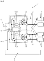
- the motor vehicle supply network 2 shown has a plurality of load current paths 4, via each of which a connected or connected load 6 is supplied with electrical power as required.
- Each load 6 is connected to a power distributor 12 with the aid of a cable 8, which has a connection element designed as a plug 10 at both ends, so that each load current path 4 is formed at least in sections by a cable 8.
- the power distributor 12 is connected to a power source 14 which makes electrical power available in the motor vehicle supply network 2 and feeds it into the power distributor 12 for this purpose.
- a supply current path 16 via which the power distributor 12 is connected to the power source 14 and via which electrical power from the power source 14 reaches the power distributor 12, splits into the load current paths 4, via which the loads 6 are quasi-end consumers be supplied with electrical power.
- the power requirement is between 500 W and 1500 W, depending on the load 6, and the motor vehicle supply network 2 is accordingly designed to supply electrical consumers with a relatively high power requirement.
- the motor vehicle supply network 2 is designed for a motor vehicle and has a safety system with the aid of which the motor vehicle supply network 2 protects against both overcurrent accidents and arcing accidents and consequential damage resulting therefrom is secured.
- the safety system is designed in such a way that each load current path 4 is monitored and that the load 6 supplied via a load current path 4 is cut off from the supply as soon as an impending incident is detected in the corresponding load current path 4.
- the basic principle of monitoring is explained below using the in Fig. 1
- the simplified motor vehicle supply network 2 illustrated which only comprises a load current path 4 and, accordingly, a load 6, is explained.
- This basic principle can, however, be transferred without problems to a plurality of load current paths 4 and, accordingly, to a plurality of loads 6 and thus also in the motor vehicle supply network 2 according to FIG Fig. 2 use.
- the power distributor 12 which is shown in FIG Fig. 1 like in Fig. 2 is marked by a dashed border, a plurality of functional units or functional modules, which in the exemplary embodiment are accommodated on a common printed circuit board and surrounded by a common housing.
- a functional unit is provided by a semiconductor switch 18, which is opened or blocked when an impending incident is detected in order to decouple the load 6 from the supply of electrical energy, i.e. to switch off the electrical consumer that is supplied via the corresponding load current path 4.
- the semiconductor switch 18 is integrated in the corresponding load current path 4 and is also used to switch the corresponding electrical consumer on and off as required.
- the power distributor 12 comprises a current measuring unit 20, with the aid of which the current flowing via the load current path 4 is monitored by detecting the current strength.
- the current measuring unit 20 is connected directly to a current measuring output on the semiconductor switch 18 for signaling purposes, or the current measuring unit 20 is completely integrated into the semiconductor switch 18.
- the power distributor 12 comprises a voltage measuring unit 22, which is divided into a circuit shown in FIG Fig. 1 only partially shown voltage measuring bridge is integrated. This is based on the principle of a Wheadston measuring bridge and is already in the one that goes back to the applicant DE 10 2012 019 996 A1 described, which is why at this point reference is expressly made to this laid-open specification.
- Both the current measuring unit 20 and the voltage measuring unit 22 together with the voltage measuring bridge 24 serve only to record a current strength and a voltage, whereas the evaluation of the recorded measurement data, in particular the time profile of the recorded current intensity and the time profile of the recorded voltage, is carried out in a monitoring unit 26 takes place, which is part of the power distributor 12 as a further functional unit of the security system.
- a monitoring unit 26 there is then a comparison of the current intensity detected by the current measuring unit 20 with several current profiles stored in a memory of the monitoring unit 26 which reproduce a characteristic temporal course of the current intensity before and when an incident occurs, whereby a comparable temporal course of the by means of the current measuring unit 20 detected amperage can be inferred to an impending incident.
- An analog evaluation of the measurement data of the voltage measuring unit 22 takes place in parallel, with several voltage profiles again being stored in the memory of the monitoring unit 26 for this purpose.
- the monitoring unit 26 is designed in such a way that the detection of impending overcurrent accidents is recognized only when a characteristic time profile of the current intensity occurs in the load current path 4, whereas the impending arc accidents are recognized when both a characteristic time profile of the current intensity and a characteristic time profile of the voltage detected by means of the voltage measuring unit 22 is determined. In this way, different types of threatening incidents are recognized as threatening incidents, regardless of the type of threatening incident In the event of a fault, the monitoring unit 26 reacts in such a way that it initiates the opening or blocking of the semiconductor switch 18 and for this purpose transmits a control signal to an amplifier 28.
- a fault log is generated in the monitoring unit 26 and transmitted via a signal output 30 on the power distributor 12 to an external receiver, in the exemplary embodiment a control unit 32 in the vehicle's electrical system.
- the fault log is then incorporated into an error log and stored in an error memory, which is typically read out by a maintenance technician during maintenance of the motor vehicle. This then makes the maintenance technician aware of the problem at hand.
- the error log also contains information on the load current path 4 of the motor vehicle supply network 2 in which the problem is present. Apart from that, the individual load current paths 4 of the motor vehicle supply network 2 are monitored in accordance with Fig. 2 according to the same principle as in the case of the motor vehicle supply network 2 Fig. 1 , a separate semiconductor switch 18, a separate current measuring unit 20 and a separate voltage measuring bridge 24 with an integrated voltage measuring unit 22 being provided for each load current path 4 and being implemented accordingly in the power distributor 12.
- the evaluation of the measurement data belonging to the individual load current paths 4, takes place in a single monitoring unit 26, which is accordingly connected to all of the current measurement units 20 and all of the voltage measurement units 22 in the power distributor 12.
- the one monitoring unit 26 controls the semiconductor switch 18 belonging to the corresponding load current path 4, whereby the corresponding load current path 4 is disconnected from the power supply.
- the control in the exemplary embodiment takes place in accordance with Fig. 2 directly through the Monitoring unit 26, which is constructed in the manner of a microcontroller and has an integrated signal amplifier for controlling the semiconductor switches 18 in the power distributor 12.
- Fig. 1 two resistors 34 shown in the area of the load 6 and a sensor line or signal line 36 are also shown, which are part of the voltage measuring bridge 24 and in Fig. 2 are not explicitly shown, but are implemented for each load current path 4 in the motor vehicle supply network 2.
- the corresponding resistors 34 are in each case integrated in the load-side connector 10 of each cable 8 and the signal line 36 is provided either by an additional wire in each cable 8 or by shielding in each cable 8.
Landscapes
- Engineering & Computer Science (AREA)
- Mechanical Engineering (AREA)
- Power Engineering (AREA)
- Combustion & Propulsion (AREA)
- Physics & Mathematics (AREA)
- General Physics & Mathematics (AREA)
- Chemical & Material Sciences (AREA)
- Transportation (AREA)
- Emergency Protection Circuit Devices (AREA)
- Electric Propulsion And Braking For Vehicles (AREA)
- Control Of Electric Motors In General (AREA)
- Direct Current Feeding And Distribution (AREA)
- Control Of Direct Current Motors (AREA)
Claims (13)
- Réseau d'alimentation (2) de véhicule automobile, en particulier réseau de bord 48V d'un véhicule automobile, comprenant une source de courant (14), un distributeur de puissance (12) qui est relié à la source de courant (14) via un trajet de courant d'alimentation (16), ainsi qu'au moins une charge (6) qui est reliée au distributeur de puissance (12) via un trajet de courant de charge (4) à commutateur à semi-conducteur (18) intégré et est reliée à la source de courant (14) via le distributeur de puissance (12),dans lequel une unité de mesure de courant (20), une unité de mesure de tension (22) ainsi qu'une unité de surveillance (26) sont intégrées dans le distributeur de puissance (12) et l'unité de surveillance (26) étant disposée de telle façon qu'elle détecte une défaillance imminente à l'aide des données de mesure de l'unité de mesure de courant (20) et/ou des données de mesure de l'unité de mesure de tension (22) et de telle façon qu'elle déclenche une mise hors circuit de ladite au moins une charge (6) au moyen du commutateur à semi-conducteur (18), aussi bien des défaillances de surintensité imminentes que des défaillances d'arc électrique imminentes étant détectées en tant que défaillance imminente,dans lequel le trajet de courant d'alimentation (16) se divise dans le distributeur de puissance (12) en plusieurs trajets de courant de charge (4) et une charge (6) est reliée via chacun de ces trajets de courant de charge (4) au distributeur de puissance (12), dans lequel un commutateur à semi-conducteur (18) est intégré dans chaque trajet de courant de charge (4), et dans lequel l'unité de surveillance (26) est disposée pour surveiller tous les trajets de courant de charge (4) indépendamment les uns des autres, de sorte qu'en cas d'une défaillance dans l'un des trajet de courant de charge (4) seulement la charge (6) qui y est reliée est mise hors circuit.
- Réseau d'alimentation (2) de véhicule automobile selon la revendication 1,
dans lequel au moins le commutateur à semi-conducteur intégré dans le trajet de courant de charge (4) avec ladite au moins une charge est conçu sous forme de transistor de puissance et en particulier sous forme de MOSFET. - Réseau d'alimentation (2) de véhicule automobile selon la revendication 1 ou 2,
dans lequel sur une carte à circuit imprimé commune sont disposés pour chacune des charges (6) un commutateur à semi-conducteur (18) respectif, une unité de mesure de courant (20) respective, une unité de mesure de tension (22) respective ainsi qu'une unité de surveillance (26) commune pour toutes les charges (6), qui pour chaque charge (6) est conçue pour la détection- d'une surintensité,- d'un court-circuit du trajet de courant de charge (4) à la masse,- d'un arc électrique en parallèle dans le trajet de courant de charge (4),- d'un arc électrique en série dans le trajet de courant de charge (4) ainsi que pour la détection- d'un arc électrique en série dans un trajet à la masse entre la charge (4) respective et un potentiel de masse. - Réseau d'alimentation (2) de véhicule automobile selon l'une quelconque des revendications 1 à 3,
dans lequel pour la surveillance du trajet de courant (4) avec ladite au moins une charge (6) l'unité de mesure de courant (20) est intégrée dans le commutateur à semi-conducteur (18) du trajet de courant de charge (4) correspondant. - Réseau d'alimentation (2) de véhicule automobile selon l'une quelconque des revendications 1 à 4,
dans lequel l'unité de surveillance (26) est disposée pour détecter une défaillance imminente et la nature de la défaillance imminente. - Réseau d'alimentation (2) de véhicule automobile selon l'une quelconque des revendications 1 à 5,
dans lequel l'unité de surveillance (26) est disposée pour détecter une défaillance imminente et la nature de la défaillance imminente en comparant les données de mesure de l'unité de mesure de courant (20) et/ou les données de mesure de l'unité de mesure de tension (22) à des profils de courant et/ou de tension enregistrés. - Réseau d'alimentation (2) de véhicule automobile selon la revendication 5 ou la revendication 6,
dans lequel l'unité de surveillance (26) est disposée de telle façon que lorsqu'une défaillance imminente a été détectée un protocole de défaillance est engendré et transmis à un récepteur via une sortie de signal (30) sur le distributeur de puissance (12). - Réseau d'alimentation (2) de véhicule automobile selon l'une quelconque des revendications 1 à 7,
dans lequel dans la détection de défaillances d'arc électrique imminentes dans un trajet de courant de charge (4) l'unité de surveillance (26) surveille la différence de potentiel déterminée au moyen de l'unité de mesure de tension (22) dans un pont de mesure (24) comportant une tête de pont dans la zone de la charge (6) de ce trajet de courant de charge (4) et comportant une tête de pont dans la zone du commutateur à semi-conducteur (18) de ce trajet de courant de charge (4). - Réseau d'alimentation (2) de véhicule automobile selon la revendication 8,
dans lequel la configuration des ponts de mesure (24) est basée sur le principe des ponts de mesure de Wheatstone. - Réseau d'alimentation (2) de véhicule automobile selon la revendication 8 ou la revendication 9,
dans lequel une ligne de capteur (36) est conduite dans le distributeur de puissance (12) en sortant de la tête de pont dans la zone de la charge (6), qui au moins dans un segment est constituée d'un conducteur ou d'un blindage d'un câble (8) de transmission de puissance, par lequel la charge (6) est reliée au distributeur de puissance (12). - Réseau d'alimentation (2) de véhicule automobile selon l'une quelconque des revendications 8 à 10,
dans lequel la tête de pont dans la zone de la charge (6) est intégrée dans un connecteur à fiche (10) d'un câble (8) de transmission de puissance, par lequel la charge (6) est reliée au distributeur de puissance (12). - Réseau d'alimentation (2) de véhicule automobile selon la revendication 1,dans lequel au moins le commutateur à semi-conducteur intégré dans le trajet de courant de charge avec ladite au moins une charge est conçu sous forme de transistor de puissance,dans lequel sur une carte à circuit imprimé commune sont disposés pour chacune des charges (6) un commutateur à semi-conducteur (18) respectif, une unité de mesure de courant (20) respective, une unité de mesure de tension (22) respective ainsi qu'une unité de surveillance (26) commune pour toutes les charges (6), qui pour chaque charge (6) est conçue pour la détection- d'une surintensité,- d'un court-circuit du trajet de courant de charge (4) à la masse,- d'un arc électrique en parallèle dans le trajet de courant de charge (4),- d'un arc électrique en série dans le trajet de courant de charge (4) ainsi que pour la détection- d'un arc électrique en série dans un trajet à la masse entre la charge (4) respective et un potentiel de masse,dans lequel, dans la détection de défaillances d'arc électrique imminentes dans un trajet de courant de charge (4), l'unité de surveillance (26) surveille la différence de potentiel déterminée au moyen de l'unité de mesure de tension (22) dans un pont de mesure (24) comportant une tête de pont dans la zone de la charge (6) de ce trajet de courant de charge (4) et comportant une tête de pont dans la zone du commutateur à semi-conducteur (18) de ce trajet de courant de charge (4),dans lequel la tête de pont dans la zone de la charge (6) est intégrée dans un connecteur à fiche (10) d'un câble (8) de transmission de puissance, par lequel la charge (6) est reliée au distributeur de puissance (12).
- Distributeur de puissance (12) pour un réseau d'alimentation (2) de véhicule automobile selon l'une quelconque des revendications précédentes,dans lequel sont intégrées une unité de mesure de courant (20), une unité de mesure de tension (22) ainsi qu'une unité de surveillance (26), dans lequel le distributeur de puissance (12) est disposé de telle façon qu'il peut être connecté, du côté de l'entrée, à la source de courant (14) via un trajet de courant d'alimentation (10) et, du côté de la sortie, à au moins une charge (6), de sorte qu'une source de courant (14) peut être connectée à au moins une charge (6) via le distributeur de puissance (12), etdans lequel l'unité de surveillance (26) est disposée de telle façon qu'elle détecte une défaillance imminente à l'aide des données de mesure de l'unité de mesure de courant (20) et/ou des données de mesure de l'unité de mesure de tension (22) et de telle façon qu'elle déclenche une mise hors circuit de ladite au moins une charge (6) au moyen du commutateur à semi-conducteur (18), aussi bien des défaillances de surintensité imminentes que des défaillances d'arc électrique imminentes étant détectées en tant que défaillance imminente, dans lequel le distributeur de puissance (12) est conçu de telle façon que le trajet de courant d'alimentation (16) se divise dans le distributeur de puissance (12) en plusieurs trajets de courant de charge (4) et une charge (6) peut être reliée via chacun de ces trajets de courant de charge (4) au distributeur de puissance (12), dans lequel un commutateur à semi-conducteur (18) est intégré dans chaque trajet de courant de charge (4), et dans lequel l'unité de surveillance (26) est disposée pour surveiller tous les trajets de courant de charge (4) indépendamment les uns des autres, de sorte qu'en cas d'une défaillance dans l'un des trajets de courant de charge (4) seulement la charge (6) qui y est reliée est mise hors circuit.
Applications Claiming Priority (2)
| Application Number | Priority Date | Filing Date | Title |
|---|---|---|---|
| DE102014222878.6A DE102014222878A1 (de) | 2014-11-10 | 2014-11-10 | Kraftfahrzeug-Versorgungsnetz |
| PCT/EP2015/076146 WO2016075106A1 (fr) | 2014-11-10 | 2015-11-10 | Réseau d'alimentation de vehicule automobile |
Publications (2)
| Publication Number | Publication Date |
|---|---|
| EP3218230A1 EP3218230A1 (fr) | 2017-09-20 |
| EP3218230B1 true EP3218230B1 (fr) | 2021-12-29 |
Family
ID=54780253
Family Applications (1)
| Application Number | Title | Priority Date | Filing Date |
|---|---|---|---|
| EP15804332.3A Not-in-force EP3218230B1 (fr) | 2014-11-10 | 2015-11-10 | Réseau d'alimentation de vehicule automobile |
Country Status (6)
| Country | Link |
|---|---|
| US (1) | US10518643B2 (fr) |
| EP (1) | EP3218230B1 (fr) |
| KR (1) | KR101936796B1 (fr) |
| CN (1) | CN107000661B (fr) |
| DE (1) | DE102014222878A1 (fr) |
| WO (1) | WO2016075106A1 (fr) |
Families Citing this family (18)
| Publication number | Priority date | Publication date | Assignee | Title |
|---|---|---|---|---|
| DE102016216213A1 (de) * | 2016-08-29 | 2018-03-01 | Robert Bosch Gmbh | Verfahren und Schaltungsanordnung zum Trennen einer Spannungsquelle von mindestens einem Verbraucher |
| DE102016123063B4 (de) * | 2016-11-30 | 2023-01-05 | Lisa Dräxlmaier GmbH | Verfahren und ansteuereinrichtung zum sequenzgesteuerten ansteuern von lasten an einem stromverteiler für ein kraftfahrzeug |
| DE102018206648B4 (de) * | 2017-05-03 | 2020-03-26 | Leoni Bordnetz-Systeme Gmbh | Leitungsnetz sowie Versorgungsleitung für ein solches Leitungsnetz |
| FR3067122B1 (fr) * | 2017-06-06 | 2021-05-07 | Renault Sas | Diagnostic d'une charge electrique de vehicule automobile |
| JP7094670B2 (ja) * | 2017-07-03 | 2022-07-04 | 矢崎総業株式会社 | 設定装置及びコンピュータ |
| DE102018212345A1 (de) * | 2018-07-25 | 2020-01-30 | Robert Bosch Gmbh | Verfahren zum Abgleich einer Messeinrichtung in einem Kraftfahrzeug |
| DE102018212351A1 (de) * | 2018-07-25 | 2020-01-30 | Robert Bosch Gmbh | Verfahren zur Diagnose eines Schaltmittels in einem Kraftfahrzeug |
| KR102606983B1 (ko) * | 2018-11-29 | 2023-11-29 | 현대자동차주식회사 | 차량 및 그 제어방법 |
| DE102018131199B4 (de) | 2018-12-06 | 2021-05-06 | Lisa Dräxlmaier GmbH | Herstellungsverfahren für ein fahrzeugbordnetz eines fahrzeugs sowie fahrzeugbordnetz |
| ES2906399T3 (es) * | 2019-04-08 | 2022-04-18 | Siemens Ag | Localización de una falla a tierra en una red de corriente continua |
| DE102019211155A1 (de) * | 2019-07-26 | 2021-01-28 | Volkswagen Aktiengesellschaft | Verfahren eines Fahrzeugs und eines Netzwerkservers zum Warten von Fahrzeugkomponenten |
| DE102019213010A1 (de) * | 2019-08-29 | 2021-03-18 | Volkswagen Aktiengesellschaft | Verfahren und System zum Bestimmen eines Bordnetzzustands von mindestens einem Kraftfahrzeug |
| DE102019127733B4 (de) * | 2019-10-15 | 2021-06-02 | Leoni Bordnetz-Systeme Gmbh | System und Verfahren zum Erkennen von nicht schaltenden Halbleiterschaltern |
| DE102020204076A1 (de) * | 2020-03-30 | 2021-09-30 | Zf Friedrichshafen Ag | Steuergerät zum Steuern einer Fahrzeugfunktion für ein Fahrzeug und Verfahren zum Betreiben eines Steuergeräts |
| DE102020128054B4 (de) | 2020-10-26 | 2023-02-02 | Audi Aktiengesellschaft | Verfahren zur Detektion eines Lichtbogenfehlers in einer elektrischen Schaltungsanordnung und Kraftfahrzeug |
| CN113561914A (zh) * | 2021-07-20 | 2021-10-29 | 英博超算(南京)科技有限公司 | 一种具有故障记录功能的汽车智能电源盒子 |
| DE102022002993B4 (de) * | 2022-08-16 | 2024-07-11 | Mercedes-Benz Group AG | Energiemanagement-Verfahren und Energiemanagement-System für ein Fahrzeug |
| KR102870438B1 (ko) * | 2024-01-03 | 2025-10-14 | 영화테크(주) | 전원 분배 모듈의 자동 보정 장치 및 방법 |
Family Cites Families (14)
| Publication number | Priority date | Publication date | Assignee | Title |
|---|---|---|---|---|
| JP2819828B2 (ja) * | 1990-11-30 | 1998-11-05 | 日産自動車株式会社 | 電気自動車の電源装置 |
| US6037749A (en) | 1995-06-21 | 2000-03-14 | Batteryguard Limited | Battery monitor |
| DE10132952B4 (de) * | 2001-07-06 | 2006-03-09 | Leoni Bordnetz-Systeme Gmbh & Co Kg | Verfahren zum Schutz eines Leitungsnetzes bei Auftreten eines seriellen Lichtbogens |
| US7136266B2 (en) * | 2002-10-09 | 2006-11-14 | Leviton Manufacturing Co., Inc. | Leakage current detection interrupter extension cord with cord diagnostics |
| DE10333674B4 (de) * | 2003-07-24 | 2015-07-23 | Bayerische Motoren Werke Aktiengesellschaft | Lichtbogenüberwachungssystem in einem Bordnetz |
| US7243246B2 (en) * | 2003-12-19 | 2007-07-10 | Dell Products L.P. | System having a power adapter that generates a data signal based on the state of a external power source that is used to manage the power consumption of a CPU |
| DE102006052318A1 (de) * | 2006-11-07 | 2008-05-08 | Bayerische Motoren Werke Ag | Kraftfahrzeug |
| DE102010007784A1 (de) * | 2010-02-12 | 2011-08-18 | FESTO AG & Co. KG, 73734 | Vorrichtung zur elektrischen Stromkreisüberwachung |
| US8645103B2 (en) * | 2010-03-18 | 2014-02-04 | Arthur L. Cohen | Method for capture, aggregation, and transfer of data to determine windshield wiper motion in a motor vehicle |
| JP5140113B2 (ja) * | 2010-05-10 | 2013-02-06 | 三菱電機株式会社 | 電子制御装置 |
| DE102010053816B4 (de) * | 2010-12-08 | 2015-02-12 | Audi Ag | Vorrichtung zum Erkennen eines Lichtbogens und zugehöriges Verfahren |
| DE102012019996A1 (de) | 2012-10-12 | 2014-04-17 | Leoni Bordnetz-Systeme Gmbh | Leitungsnetz, insbesondere Gleichspannungs-Bordnetz für ein Kraftfahrzeug sowie Verfahren zur Überwachung eines Leitungsnetzes auf das Entstehen eines Lichtbogens |
| DE102012023460B4 (de) * | 2012-11-30 | 2024-11-21 | Volkswagen Aktiengesellschaft | Kraftfahrzeug-Bordnetz und Verfahren zum Erkennen eines Lichtbogens in einem Kraftfahrzeug-Bordnetz |
| DE102014202626A1 (de) * | 2014-02-13 | 2015-08-13 | Robert Bosch Gmbh | Batteriemanagementsystem für eine Batterie mit mehreren Batteriezellen und Verfahren |
-
2014
- 2014-11-10 DE DE102014222878.6A patent/DE102014222878A1/de not_active Withdrawn
-
2015
- 2015-11-10 CN CN201580061081.9A patent/CN107000661B/zh not_active Expired - Fee Related
- 2015-11-10 WO PCT/EP2015/076146 patent/WO2016075106A1/fr not_active Ceased
- 2015-11-10 EP EP15804332.3A patent/EP3218230B1/fr not_active Not-in-force
- 2015-11-10 KR KR1020177015194A patent/KR101936796B1/ko not_active Expired - Fee Related
-
2017
- 2017-05-10 US US15/591,660 patent/US10518643B2/en not_active Expired - Fee Related
Also Published As
| Publication number | Publication date |
|---|---|
| US20170240049A1 (en) | 2017-08-24 |
| CN107000661A (zh) | 2017-08-01 |
| KR101936796B1 (ko) | 2019-01-09 |
| KR20170078827A (ko) | 2017-07-07 |
| CN107000661B (zh) | 2019-08-13 |
| EP3218230A1 (fr) | 2017-09-20 |
| DE102014222878A1 (de) | 2016-05-12 |
| US10518643B2 (en) | 2019-12-31 |
| WO2016075106A1 (fr) | 2016-05-19 |
Similar Documents
| Publication | Publication Date | Title |
|---|---|---|
| EP3218230B1 (fr) | Réseau d'alimentation de vehicule automobile | |
| DE102014214840B4 (de) | Vorrichtung zur Überwachung eines Hochvolt-Bordnetzes eines elektrisch betriebenen Fahrzeugs auf das Vorliegen einer Überlastung | |
| DE102011014343A1 (de) | Sicherungsvorrichtung für eine Spannungsversorgung eines Kraftfahrzeugs | |
| DE19811626A1 (de) | Stromversorgungsanlage für Fahrzeug | |
| EP4084249B1 (fr) | Réseau embarqué; en particulier pour un véhicule automobile | |
| DE102015107718B4 (de) | Vorrichtung und Verfahren zum Absichern einer Bordnetz-Komponente eines Fahrzeug-Bordnetzes | |
| DE102011083582A1 (de) | Stromverteiler für Kraftfahrzeug-Bordnetze | |
| DE102012018321A1 (de) | Verfahren zum Abschalten eines Batteriesystems unter Last sowie Batteriesystem | |
| EP3452336B1 (fr) | Dispositif de commande multi-tension pour véhicule automobile, véhicule automobile et procédé de fonctionnement du dispositif de commande | |
| DE102012023460B4 (de) | Kraftfahrzeug-Bordnetz und Verfahren zum Erkennen eines Lichtbogens in einem Kraftfahrzeug-Bordnetz | |
| DE102016121447B4 (de) | Vorrichtung und Verfahren zum Absichern einer Bordnetzkomponente eines Fahrzeug-Bordnetzes | |
| EP3161918B1 (fr) | Procédé et dispositif de détection d'arc électrique | |
| DE102015000576A1 (de) | Kraftfahrzeug mit Schaltvorrichtung für eine bordnetzbetriebene Komponente | |
| DE10110046A1 (de) | Vorrichtung zum Ansteuern elektrischer Verbraucher in einem Kraftfahrzeug | |
| DE10333674B4 (de) | Lichtbogenüberwachungssystem in einem Bordnetz | |
| DE102013012578B4 (de) | Vorrichtung zum Absichern einer elektrischen Leitung sowie Verfahren zum Betreiben einer auf einer elektrischen Leitung angeordneten Vorrichtung | |
| DE102012023461B3 (de) | Kraftfahrzeug-Bordnetz und Verfahren zum Erkennen eines Lichtbogens in einem Hauptleistungspfad des Kraftfahrzeug-Bordnetzes | |
| EP2633738B2 (fr) | Ensemble composé d'un appareil de commande de réseau électrique de bord et d'au moins un variateur d'éclairage d'un véhicule automobile | |
| EP3820733B1 (fr) | Dispositif de batterie multi-tension et réseau de bord pour un véhicule automobile | |
| DE102017221935A1 (de) | Schutzvorrichtung und Verfahren zur Absicherung eines Hochvoltnetzes sowie elektrisches Antriebssystem | |
| DE102016224810A1 (de) | Kraftfahrzeug mit einem Elektromotor, insbesondere Hybrid- oder Elektrofahrzeug | |
| DE102012023459B3 (de) | Verfahren und Vorrichtung zur Detektion von Lichtbögen in einem Kraftfahrzeug-Bordnetz | |
| DE102015016696A1 (de) | Kurzschlusserkennung durch Lichtsignal und Einleitung der Fahrzeugreaktion | |
| DE10243372B4 (de) | Sicherheitseinrichtung für Leistungsschaltung und Sicherungskasten | |
| EP1932400B1 (fr) | Dispositif pour reconnaitre des defaillances de tension dans un appareil electronique |
Legal Events
| Date | Code | Title | Description |
|---|---|---|---|
| STAA | Information on the status of an ep patent application or granted ep patent |
Free format text: STATUS: THE INTERNATIONAL PUBLICATION HAS BEEN MADE |
|
| PUAI | Public reference made under article 153(3) epc to a published international application that has entered the european phase |
Free format text: ORIGINAL CODE: 0009012 |
|
| STAA | Information on the status of an ep patent application or granted ep patent |
Free format text: STATUS: REQUEST FOR EXAMINATION WAS MADE |
|
| 17P | Request for examination filed |
Effective date: 20170524 |
|
| AK | Designated contracting states |
Kind code of ref document: A1 Designated state(s): AL AT BE BG CH CY CZ DE DK EE ES FI FR GB GR HR HU IE IS IT LI LT LU LV MC MK MT NL NO PL PT RO RS SE SI SK SM TR |
|
| AX | Request for extension of the european patent |
Extension state: BA ME |
|
| DAV | Request for validation of the european patent (deleted) | ||
| DAX | Request for extension of the european patent (deleted) | ||
| STAA | Information on the status of an ep patent application or granted ep patent |
Free format text: STATUS: EXAMINATION IS IN PROGRESS |
|
| 17Q | First examination report despatched |
Effective date: 20190812 |
|
| GRAP | Despatch of communication of intention to grant a patent |
Free format text: ORIGINAL CODE: EPIDOSNIGR1 |
|
| STAA | Information on the status of an ep patent application or granted ep patent |
Free format text: STATUS: GRANT OF PATENT IS INTENDED |
|
| INTG | Intention to grant announced |
Effective date: 20210705 |
|
| GRAJ | Information related to disapproval of communication of intention to grant by the applicant or resumption of examination proceedings by the epo deleted |
Free format text: ORIGINAL CODE: EPIDOSDIGR1 |
|
| GRAL | Information related to payment of fee for publishing/printing deleted |
Free format text: ORIGINAL CODE: EPIDOSDIGR3 |
|
| GRAS | Grant fee paid |
Free format text: ORIGINAL CODE: EPIDOSNIGR3 |
|
| STAA | Information on the status of an ep patent application or granted ep patent |
Free format text: STATUS: EXAMINATION IS IN PROGRESS |
|
| GRAJ | Information related to disapproval of communication of intention to grant by the applicant or resumption of examination proceedings by the epo deleted |
Free format text: ORIGINAL CODE: EPIDOSDIGR1 |
|
| GRAL | Information related to payment of fee for publishing/printing deleted |
Free format text: ORIGINAL CODE: EPIDOSDIGR3 |
|
| INTC | Intention to grant announced (deleted) | ||
| GRAP | Despatch of communication of intention to grant a patent |
Free format text: ORIGINAL CODE: EPIDOSNIGR1 |
|
| STAA | Information on the status of an ep patent application or granted ep patent |
Free format text: STATUS: GRANT OF PATENT IS INTENDED |
|
| INTG | Intention to grant announced |
Effective date: 20211020 |
|
| GRAA | (expected) grant |
Free format text: ORIGINAL CODE: 0009210 |
|
| STAA | Information on the status of an ep patent application or granted ep patent |
Free format text: STATUS: THE PATENT HAS BEEN GRANTED |
|
| AK | Designated contracting states |
Kind code of ref document: B1 Designated state(s): AL AT BE BG CH CY CZ DE DK EE ES FI FR GB GR HR HU IE IS IT LI LT LU LV MC MK MT NL NO PL PT RO RS SE SI SK SM TR |
|
| REG | Reference to a national code |
Ref country code: GB Ref legal event code: FG4D Free format text: NOT ENGLISH |
|
| REG | Reference to a national code |
Ref country code: CH Ref legal event code: EP |
|
| REG | Reference to a national code |
Ref country code: DE Ref legal event code: R096 Ref document number: 502015015532 Country of ref document: DE |
|
| REG | Reference to a national code |
Ref country code: AT Ref legal event code: REF Ref document number: 1458454 Country of ref document: AT Kind code of ref document: T Effective date: 20220115 |
|
| REG | Reference to a national code |
Ref country code: IE Ref legal event code: FG4D Free format text: LANGUAGE OF EP DOCUMENT: GERMAN |
|
| REG | Reference to a national code |
Ref country code: LT Ref legal event code: MG9D |
|
| PG25 | Lapsed in a contracting state [announced via postgrant information from national office to epo] |
Ref country code: RS Free format text: LAPSE BECAUSE OF FAILURE TO SUBMIT A TRANSLATION OF THE DESCRIPTION OR TO PAY THE FEE WITHIN THE PRESCRIBED TIME-LIMIT Effective date: 20211229 Ref country code: LT Free format text: LAPSE BECAUSE OF FAILURE TO SUBMIT A TRANSLATION OF THE DESCRIPTION OR TO PAY THE FEE WITHIN THE PRESCRIBED TIME-LIMIT Effective date: 20211229 Ref country code: FI Free format text: LAPSE BECAUSE OF FAILURE TO SUBMIT A TRANSLATION OF THE DESCRIPTION OR TO PAY THE FEE WITHIN THE PRESCRIBED TIME-LIMIT Effective date: 20211229 Ref country code: BG Free format text: LAPSE BECAUSE OF FAILURE TO SUBMIT A TRANSLATION OF THE DESCRIPTION OR TO PAY THE FEE WITHIN THE PRESCRIBED TIME-LIMIT Effective date: 20220329 |
|
| REG | Reference to a national code |
Ref country code: NL Ref legal event code: MP Effective date: 20211229 |
|
| PG25 | Lapsed in a contracting state [announced via postgrant information from national office to epo] |
Ref country code: SE Free format text: LAPSE BECAUSE OF FAILURE TO SUBMIT A TRANSLATION OF THE DESCRIPTION OR TO PAY THE FEE WITHIN THE PRESCRIBED TIME-LIMIT Effective date: 20211229 Ref country code: NO Free format text: LAPSE BECAUSE OF FAILURE TO SUBMIT A TRANSLATION OF THE DESCRIPTION OR TO PAY THE FEE WITHIN THE PRESCRIBED TIME-LIMIT Effective date: 20220329 Ref country code: LV Free format text: LAPSE BECAUSE OF FAILURE TO SUBMIT A TRANSLATION OF THE DESCRIPTION OR TO PAY THE FEE WITHIN THE PRESCRIBED TIME-LIMIT Effective date: 20211229 Ref country code: HR Free format text: LAPSE BECAUSE OF FAILURE TO SUBMIT A TRANSLATION OF THE DESCRIPTION OR TO PAY THE FEE WITHIN THE PRESCRIBED TIME-LIMIT Effective date: 20211229 Ref country code: GR Free format text: LAPSE BECAUSE OF FAILURE TO SUBMIT A TRANSLATION OF THE DESCRIPTION OR TO PAY THE FEE WITHIN THE PRESCRIBED TIME-LIMIT Effective date: 20220330 |
|
| PG25 | Lapsed in a contracting state [announced via postgrant information from national office to epo] |
Ref country code: NL Free format text: LAPSE BECAUSE OF FAILURE TO SUBMIT A TRANSLATION OF THE DESCRIPTION OR TO PAY THE FEE WITHIN THE PRESCRIBED TIME-LIMIT Effective date: 20211229 |
|
| PG25 | Lapsed in a contracting state [announced via postgrant information from national office to epo] |
Ref country code: SM Free format text: LAPSE BECAUSE OF FAILURE TO SUBMIT A TRANSLATION OF THE DESCRIPTION OR TO PAY THE FEE WITHIN THE PRESCRIBED TIME-LIMIT Effective date: 20211229 Ref country code: SK Free format text: LAPSE BECAUSE OF FAILURE TO SUBMIT A TRANSLATION OF THE DESCRIPTION OR TO PAY THE FEE WITHIN THE PRESCRIBED TIME-LIMIT Effective date: 20211229 Ref country code: RO Free format text: LAPSE BECAUSE OF FAILURE TO SUBMIT A TRANSLATION OF THE DESCRIPTION OR TO PAY THE FEE WITHIN THE PRESCRIBED TIME-LIMIT Effective date: 20211229 Ref country code: PT Free format text: LAPSE BECAUSE OF FAILURE TO SUBMIT A TRANSLATION OF THE DESCRIPTION OR TO PAY THE FEE WITHIN THE PRESCRIBED TIME-LIMIT Effective date: 20220429 Ref country code: ES Free format text: LAPSE BECAUSE OF FAILURE TO SUBMIT A TRANSLATION OF THE DESCRIPTION OR TO PAY THE FEE WITHIN THE PRESCRIBED TIME-LIMIT Effective date: 20211229 Ref country code: EE Free format text: LAPSE BECAUSE OF FAILURE TO SUBMIT A TRANSLATION OF THE DESCRIPTION OR TO PAY THE FEE WITHIN THE PRESCRIBED TIME-LIMIT Effective date: 20211229 Ref country code: CZ Free format text: LAPSE BECAUSE OF FAILURE TO SUBMIT A TRANSLATION OF THE DESCRIPTION OR TO PAY THE FEE WITHIN THE PRESCRIBED TIME-LIMIT Effective date: 20211229 |
|
| PG25 | Lapsed in a contracting state [announced via postgrant information from national office to epo] |
Ref country code: PL Free format text: LAPSE BECAUSE OF FAILURE TO SUBMIT A TRANSLATION OF THE DESCRIPTION OR TO PAY THE FEE WITHIN THE PRESCRIBED TIME-LIMIT Effective date: 20211229 |
|
| PG25 | Lapsed in a contracting state [announced via postgrant information from national office to epo] |
Ref country code: IS Free format text: LAPSE BECAUSE OF FAILURE TO SUBMIT A TRANSLATION OF THE DESCRIPTION OR TO PAY THE FEE WITHIN THE PRESCRIBED TIME-LIMIT Effective date: 20220429 |
|
| REG | Reference to a national code |
Ref country code: DE Ref legal event code: R097 Ref document number: 502015015532 Country of ref document: DE |
|
| PG25 | Lapsed in a contracting state [announced via postgrant information from national office to epo] |
Ref country code: DK Free format text: LAPSE BECAUSE OF FAILURE TO SUBMIT A TRANSLATION OF THE DESCRIPTION OR TO PAY THE FEE WITHIN THE PRESCRIBED TIME-LIMIT Effective date: 20211229 Ref country code: AL Free format text: LAPSE BECAUSE OF FAILURE TO SUBMIT A TRANSLATION OF THE DESCRIPTION OR TO PAY THE FEE WITHIN THE PRESCRIBED TIME-LIMIT Effective date: 20211229 |
|
| PLBE | No opposition filed within time limit |
Free format text: ORIGINAL CODE: 0009261 |
|
| STAA | Information on the status of an ep patent application or granted ep patent |
Free format text: STATUS: NO OPPOSITION FILED WITHIN TIME LIMIT |
|
| 26N | No opposition filed |
Effective date: 20220930 |
|
| PG25 | Lapsed in a contracting state [announced via postgrant information from national office to epo] |
Ref country code: SI Free format text: LAPSE BECAUSE OF FAILURE TO SUBMIT A TRANSLATION OF THE DESCRIPTION OR TO PAY THE FEE WITHIN THE PRESCRIBED TIME-LIMIT Effective date: 20211229 |
|
| PG25 | Lapsed in a contracting state [announced via postgrant information from national office to epo] |
Ref country code: IT Free format text: LAPSE BECAUSE OF FAILURE TO SUBMIT A TRANSLATION OF THE DESCRIPTION OR TO PAY THE FEE WITHIN THE PRESCRIBED TIME-LIMIT Effective date: 20211229 |
|
| REG | Reference to a national code |
Ref country code: DE Ref legal event code: R119 Ref document number: 502015015532 Country of ref document: DE |
|
| PG25 | Lapsed in a contracting state [announced via postgrant information from national office to epo] |
Ref country code: MC Free format text: LAPSE BECAUSE OF FAILURE TO SUBMIT A TRANSLATION OF THE DESCRIPTION OR TO PAY THE FEE WITHIN THE PRESCRIBED TIME-LIMIT Effective date: 20211229 |
|
| REG | Reference to a national code |
Ref country code: CH Ref legal event code: PL |
|
| GBPC | Gb: european patent ceased through non-payment of renewal fee |
Effective date: 20221110 |
|
| REG | Reference to a national code |
Ref country code: BE Ref legal event code: MM Effective date: 20221130 |
|
| PG25 | Lapsed in a contracting state [announced via postgrant information from national office to epo] |
Ref country code: LI Free format text: LAPSE BECAUSE OF NON-PAYMENT OF DUE FEES Effective date: 20221130 Ref country code: CH Free format text: LAPSE BECAUSE OF NON-PAYMENT OF DUE FEES Effective date: 20221130 |
|
| PG25 | Lapsed in a contracting state [announced via postgrant information from national office to epo] |
Ref country code: LU Free format text: LAPSE BECAUSE OF NON-PAYMENT OF DUE FEES Effective date: 20221110 |
|
| PG25 | Lapsed in a contracting state [announced via postgrant information from national office to epo] |
Ref country code: IE Free format text: LAPSE BECAUSE OF NON-PAYMENT OF DUE FEES Effective date: 20221110 Ref country code: GB Free format text: LAPSE BECAUSE OF NON-PAYMENT OF DUE FEES Effective date: 20221110 Ref country code: DE Free format text: LAPSE BECAUSE OF NON-PAYMENT OF DUE FEES Effective date: 20230601 |
|
| PG25 | Lapsed in a contracting state [announced via postgrant information from national office to epo] |
Ref country code: BE Free format text: LAPSE BECAUSE OF NON-PAYMENT OF DUE FEES Effective date: 20221130 Ref country code: FR Free format text: LAPSE BECAUSE OF NON-PAYMENT OF DUE FEES Effective date: 20221130 |
|
| REG | Reference to a national code |
Ref country code: AT Ref legal event code: MM01 Ref document number: 1458454 Country of ref document: AT Kind code of ref document: T Effective date: 20221110 |
|
| PG25 | Lapsed in a contracting state [announced via postgrant information from national office to epo] |
Ref country code: AT Free format text: LAPSE BECAUSE OF NON-PAYMENT OF DUE FEES Effective date: 20221110 |
|
| PG25 | Lapsed in a contracting state [announced via postgrant information from national office to epo] |
Ref country code: HU Free format text: LAPSE BECAUSE OF FAILURE TO SUBMIT A TRANSLATION OF THE DESCRIPTION OR TO PAY THE FEE WITHIN THE PRESCRIBED TIME-LIMIT; INVALID AB INITIO Effective date: 20151110 |
|
| PG25 | Lapsed in a contracting state [announced via postgrant information from national office to epo] |
Ref country code: CY Free format text: LAPSE BECAUSE OF FAILURE TO SUBMIT A TRANSLATION OF THE DESCRIPTION OR TO PAY THE FEE WITHIN THE PRESCRIBED TIME-LIMIT Effective date: 20211229 |
|
| PG25 | Lapsed in a contracting state [announced via postgrant information from national office to epo] |
Ref country code: MK Free format text: LAPSE BECAUSE OF FAILURE TO SUBMIT A TRANSLATION OF THE DESCRIPTION OR TO PAY THE FEE WITHIN THE PRESCRIBED TIME-LIMIT Effective date: 20211229 |
|
| PG25 | Lapsed in a contracting state [announced via postgrant information from national office to epo] |
Ref country code: TR Free format text: LAPSE BECAUSE OF FAILURE TO SUBMIT A TRANSLATION OF THE DESCRIPTION OR TO PAY THE FEE WITHIN THE PRESCRIBED TIME-LIMIT Effective date: 20211229 |
|
| PG25 | Lapsed in a contracting state [announced via postgrant information from national office to epo] |
Ref country code: MT Free format text: LAPSE BECAUSE OF FAILURE TO SUBMIT A TRANSLATION OF THE DESCRIPTION OR TO PAY THE FEE WITHIN THE PRESCRIBED TIME-LIMIT Effective date: 20211229 |