EP3218246B1 - Colonne de direction comportant une butée longitudinale présentant une fonction de libération en cas d'accident - Google Patents
Colonne de direction comportant une butée longitudinale présentant une fonction de libération en cas d'accident Download PDFInfo
- Publication number
- EP3218246B1 EP3218246B1 EP15766532.4A EP15766532A EP3218246B1 EP 3218246 B1 EP3218246 B1 EP 3218246B1 EP 15766532 A EP15766532 A EP 15766532A EP 3218246 B1 EP3218246 B1 EP 3218246B1
- Authority
- EP
- European Patent Office
- Prior art keywords
- fixing element
- stop
- stop body
- steering column
- unit
- Prior art date
- Legal status (The legal status is an assumption and is not a legal conclusion. Google has not performed a legal analysis and makes no representation as to the accuracy of the status listed.)
- Active
Links
Images

Classifications
-
- B—PERFORMING OPERATIONS; TRANSPORTING
- B62—LAND VEHICLES FOR TRAVELLING OTHERWISE THAN ON RAILS
- B62D—MOTOR VEHICLES; TRAILERS
- B62D1/00—Steering controls, i.e. means for initiating a change of direction of the vehicle
- B62D1/02—Steering controls, i.e. means for initiating a change of direction of the vehicle vehicle-mounted
- B62D1/16—Steering columns
- B62D1/18—Steering columns yieldable or adjustable, e.g. tiltable
- B62D1/184—Mechanisms for locking columns at selected positions
-
- B—PERFORMING OPERATIONS; TRANSPORTING
- B62—LAND VEHICLES FOR TRAVELLING OTHERWISE THAN ON RAILS
- B62D—MOTOR VEHICLES; TRAILERS
- B62D1/00—Steering controls, i.e. means for initiating a change of direction of the vehicle
- B62D1/02—Steering controls, i.e. means for initiating a change of direction of the vehicle vehicle-mounted
- B62D1/16—Steering columns
- B62D1/18—Steering columns yieldable or adjustable, e.g. tiltable
- B62D1/185—Steering columns yieldable or adjustable, e.g. tiltable adjustable by axial displacement, e.g. telescopically
-
- B—PERFORMING OPERATIONS; TRANSPORTING
- B62—LAND VEHICLES FOR TRAVELLING OTHERWISE THAN ON RAILS
- B62D—MOTOR VEHICLES; TRAILERS
- B62D1/00—Steering controls, i.e. means for initiating a change of direction of the vehicle
- B62D1/02—Steering controls, i.e. means for initiating a change of direction of the vehicle vehicle-mounted
- B62D1/16—Steering columns
- B62D1/18—Steering columns yieldable or adjustable, e.g. tiltable
- B62D1/187—Steering columns yieldable or adjustable, e.g. tiltable with tilt adjustment; with tilt and axial adjustment
-
- B—PERFORMING OPERATIONS; TRANSPORTING
- B62—LAND VEHICLES FOR TRAVELLING OTHERWISE THAN ON RAILS
- B62D—MOTOR VEHICLES; TRAILERS
- B62D1/00—Steering controls, i.e. means for initiating a change of direction of the vehicle
- B62D1/02—Steering controls, i.e. means for initiating a change of direction of the vehicle vehicle-mounted
- B62D1/16—Steering columns
- B62D1/18—Steering columns yieldable or adjustable, e.g. tiltable
- B62D1/19—Steering columns yieldable or adjustable, e.g. tiltable incorporating energy-absorbing arrangements, e.g. by being yieldable or collapsible
- B62D1/192—Yieldable or collapsible columns
-
- B—PERFORMING OPERATIONS; TRANSPORTING
- B62—LAND VEHICLES FOR TRAVELLING OTHERWISE THAN ON RAILS
- B62D—MOTOR VEHICLES; TRAILERS
- B62D1/00—Steering controls, i.e. means for initiating a change of direction of the vehicle
- B62D1/02—Steering controls, i.e. means for initiating a change of direction of the vehicle vehicle-mounted
- B62D1/16—Steering columns
- B62D1/18—Steering columns yieldable or adjustable, e.g. tiltable
- B62D1/19—Steering columns yieldable or adjustable, e.g. tiltable incorporating energy-absorbing arrangements, e.g. by being yieldable or collapsible
- B62D1/195—Yieldable supports for the steering column
Definitions
- the invention relates to an adjustable steering column for a motor vehicle according to the preamble of claim 1. Furthermore, the invention relates to a stop body for an adjustable steering column according to the preamble of claim 9 and a method for adjusting a steering column according to the preamble of claim 20th
- Generic steering columns are known in a variety of embodiments. They are also referred to as adjustable steering columns and make it possible to adjust the position of the steering wheel in the direction parallel to the steering spindle longitudinal axis and / or to perform a height adjustment in a direction transverse to the steering spindle longitudinal axis.
- the jacket unit While driving, the jacket unit is fixed in position in the console unit by means of the locking mechanism. If the locking mechanism is brought into the release position by actuation of a movably mounted locking element, the shell unit can be adjusted in at least one direction parallel and / or transverse to the steering spindle longitudinal axis relative to the vehicle-fixed console unit and thus the position of the steering wheel mounted on the steering shaft.
- the shell unit is held back to the console unit.
- the shell unit does not move relative to the console unit in the locking position of the locking element.
- the situation is different in the case where the vehicle collides with another vehicle or object.
- the so-called crash case the attached to the steering shaft steering wheel does not rigidly remain in its position, but in the event of an impact of the driver on the steering wheel back and z. B. be moved towards the engine compartment. In many cases, the kinetic energy of the driver is to be absorbed in this retreat.
- the DE102011056351A1 discloses a steering column for a motor vehicle comprising a guide tube which is adjustable along its longitudinal axis, wherein two stops are provided, which are collapsible when adjusting an operating lever in a first situation for adjusting the guide tube in the longitudinal direction and at a setting of the operating lever in a second Situation for jamming the guide tube are not collapsible with each other.
- the formation of rigid stops can in the fully inserted state of the steering column to an elastic springback, which can lead to jamming of the steering column when re-pressing the operating lever.
- the restriction of the adjustment can be lifted unintentionally, which is uncontrolled limited in the event of a crash, the displacement for energy absorption.
- a steering column for a motor vehicle comprising a jacket unit, in which a steering spindle is rotatably mounted about the steering spindle longitudinal axis, and one fixed to the motor vehicle or fixable console unit, wherein the jacket unit in or on the console unit in at least one direction parallel and / or held transversely to the steering spindle longitudinal axis adjustable and lockable by a locking mechanism in different positions and the locking mechanism has at least one about a Feststellelementschwenkachse rotatably mounted locking member, wherein the shell unit is determined in at least one locking position of the locking element in position in or on the console unit and in at least one release position of the locking element, the shell unit is adjustable relative to the console unit in at least one of the directions parallel and / or transverse to the steering spindle longitudinal axis, wherein d ie the steering column has at least one movably mounted and directly or indirectly cooperating with the locking element stop body, which is
- a stop surface of the stopper body which cooperates directly or indirectly with the locking element and the stop surface has a greater distance to the locking element pivot axis in the release position, as in the locking position.
- the abutment surface relative to the Feststellelementschwenkachse is displaceable, so that it is more spaced in the release position of the Feststellelementschwenkachse, as in the locked position.
- the increase in the distance is realized in that the opening movement of the locking element, which is the movement from the locking position to the release position, at least partially implemented in a translational movement of the stopper body, namely in a displacement with a movement component in the normal direction of the stop surface.
- the translation is preferably parallel to the steering spindle longitudinal axis, i. in the longitudinal direction of the jacket unit, namely against the direction of movement of the jacket unit in the event of a crash relative to the console unit.
- the distance between the stop surface and the locking element axis during the closing movement of the locking element ie the movement from the release position to the locking position, at least partially implemented in a displacement of the stopper body with a movement component against the normal direction of the stop surface, i. the distance between the abutment surface and the Feststellelementschwenkachse is reduced.
- the implementation of a movement of the locking element in a movement of the stopper body can be directly or indirectly.
- the stop body is integrally formed. That is, the body is a single integral component that is not formed by assembling multiple components by means of joining operations.
- the stopper body also from a Be formed multi-component plastic, which is preferably produced in an injection molding process.
- the stop body in the release position of the locking element limits the adjustability of the shell unit, so the possible adjustment.
- the stopper body In the locking position of the locking element, ie in the normal operating position, in which the vehicle is also moved, however, it is provided that the stopper body is brought into a position in which it is not engaged with the shell unit, that is out of engagement with the shell unit is or the shell unit releases. This ensures that in the case of a collision, in which the locking element is in the locking position, the stopper body has no influence on the displacement of the shell unit relative to the console unit.
- the stop surface relative to the Feststellelementschwenkachse is displaced, whereby it is achieved that when it comes in the fully inserted state of the steering column to an elastic spring back of the stop body, it does not come to a jamming of the steering column in a renewed actuation of the locking element , Furthermore, the restriction of the adjustment can be safely maintained, which ensures the shift path for energy absorption in the event of a crash and thus the full functionality can always be guaranteed.
- the locking element can in principle also be driven by a motor in order to be able to be brought from the locking position into the release position and back again.
- the locking element can be operated by hand or has a manually operable handle. This can, for. B. be mounted directly or indirectly on the console unit movable.
- the locking element can in principle be slidably and / or rotatably mounted. Preferred embodiments provide that the locking element is coupled to a manually operable lever rotatable or pivotable about the locking element pivot axis.
- the jacket unit of the steering column can have a wide variety of embodiments.
- the jacket unit is, for example, a cylindrical tube.
- the jacket unit is a square hollow profile or an open profile having. From the prior art, such embodiments are well known.
- the steering column has at least one counter-stop, preferably at least two counter-stops, wherein the stop surface of the stopper body in the release position of the locking element to limit the adjustability of the shell unit relative to the console unit in at least one of the directions parallel and / or transverse to Steering spindle longitudinal axis with the counter-stop, preferably with the counter-stops, cooperates. Active this interaction is then usually only when the stop surface of the stopper body meets the respective counter-stop.
- the counter-abutment or the counter-abutments is or are conveniently arranged directly or indirectly in or on the jacket unit.
- the counter-stop directly as a bulge in the shell unit, in the case that the shell unit is formed as a sheet-metal forming part, preferably by means of sheet metal forming formed.
- a special feature of the design according to the invention is that the stop body is not introduced with its stop surface as in the prior art only in the transverse path in the movement of a counter-stop, but is additionally displaced in the direction of the steering spindle longitudinal axis, i. parallel to the movement in the longitudinal direction of the jacket unit relative to the console unit, which corresponds to the direction of movement of the counter-stop.
- the increase in the distance between the stop surface of the stopper body and the locking element pivot axis during the transfer of the locking element from the locking position into the release position causes a reduction in the distance between the stop surface and the counter-stop.
- the stop body is fixed in its position, in the direction of the adjustability of the shell unit relative to the console unit, in or on the console unit, and the counter stop or its position, seen in the direction of adjustability of the shell unit relative to the console unit, is fixed in or on the shell unit or are.
- This can be achieved in a simple manner in that the stopper body on the as Clamping pin trained locking element is arranged.
- the stopper body is fixed in the direction of displacement with a positive connection on the clamping bolt.
- stop surface of the stopper body or the counter-stops or to provide the stop function seen only in the direction of adjustability of the sheath unit relative to the console unit and in the release position, must be fixed or fixable. In other directions and in the context of the transfer between the release position and the locking position, they can be mounted quite movable, as with the inventive displacement of the stop surface of the stopper body relative to the Feststellelementschwenkachse during transfer from the locking position to the release position, so that the distance between the Stop surface and the locking element pivot axis is increased. This can be done by an at least partial implementation of a rotational movement of the locking element pivot axis in a translational movement of the stop body, for example by a mechanical conversion device.
- the stopper body is rotatable about the locking element pivot axis, preferably on the clamping bolt.
- the locking member comprises a cam or a cam portion, said cam or cam portion cooperating with a control surface of the stopper body.
- the cam or cam portion is formed radially eccentrically with respect to the locking element pivot axis and contacted with its cam contour, the control surface of the stopper body.
- a cam together with the control surface forms a mechanical conversion device for converting a rotational movement of the locking element pivot axis into a translational movement of the stop body.
- the abutment surface is displaced with a movement component in the normal direction of the abutment surface.
- An opening movement of the locking element which is the movement from the locking position to the release position, is in this way at least partially implemented in a translational movement of the stopper body, namely in a displacement with a movement component in the normal direction of the stop surface.
- the translation preferably takes place parallel to the longitudinal axis of the jacket unit, namely against the direction of movement of the jacket unit in the event of a crash relative to the console unit
- the stop body is coupled to a biasing element.
- This biasing member biases the stopper body so that it can be transferred in a secure manner in its assigned position in the release position and in the locking position.
- the biasing element is biased both in the release position and in the locking position.
- the biasing element which may also be referred to as a spring, further biased to assist in the transfer back to the release position, the coupled with the biasing element stop body safely in its movement.
- the biasing member is used to minimize noise generated during the transfer between the release position and Verrieglungs ein.
- the spring element may be designed as a leaf spring or coil spring, since these types of springs have a simple structure and can be easily coupled to the stopper body. Furthermore, it may be advantageous to carry out the biasing element and the stopper body as a single integral component.
- the stop body is at least partially made of a plastic.
- a plastic By using a plastic on the one hand the cost of the stopper body can be reduced and on the other hand results in a reduction in mass.
- the entire stop body is made of a single plastic obtain. As a result, the production costs can be reduced again for the stop body.
- a displacement of the stop body takes place substantially in the direction of the steering spindle longitudinal axis. Due to the displacement of the stopper body in the direction of the steering spindle longitudinal axis according to the invention, the change in the distance between the stop surface of the stopper body and the Feststellelementschwenkachse, so that this distance is greater in the release position, as in the locked position. Preferably, in an existing counter-stop of the stop body is moved to this, thereby the restriction of the adjustment can be maintained safely to a special extent, which is ensured in the event of a crash, the displacement for energy absorption.
- the difference of the distance in the release position and the distance in the locking position has a value between 0.2 mm and 5 mm.
- a sufficient displacement can be achieved in order to advantageously form the stop according to the invention.
- this difference of the distance in the release position and the distance in the locking position the increase in the distance between the abutment surface of the stopper body and the Feststellelementschwenkachse between the locking position and the release position.
- the difference between the distance in the release position and the distance in the locking position is a value between 0.8 mm and 2.0 mm is particularly advantageous because such a configuration requires a small space.
- the value of the difference of the distance in the release position and the distance in the locking position between 0.5 mm and 1.0 mm.
- a stop body comprising a coupling portion for receiving a locking element of a steering column, and at least one stop surface for cooperation with a counter-stop of the steering column.
- the coupling section (84) comprises a control surface (82) for interacting with a cam section (71) on the locking element (15),
- the stop body according to the invention is characterized in that a control surface is integrated as a functional element of a transfer device for implementing a rotational movement of a locking element in a translational movement of the stop surface of the stopper body according to the invention in the stop body.
- the cam portion of the locking member tangentially contacts the control surface on or in the coupling portion with its eccentric cam contour so that upon rotation of the cam portion, a force having a force component in the normal direction, i. perpendicular to the control surface is exercised.
- the stopper body can be moved in translation.
- the cam portion forms together with the coupling portion a mechanical conversion gear, which converts a rotational or pivotal movement of the locking element in a translational displacement of the stopper body.
- the Feststellelementschwenkachse is transversely, preferably arranged perpendicular to the steering spindle longitudinal axis, so that upon rotation of the cam or cam portion via the cam contour a force is exerted on the control surface, so that a displacement of the stop body transversely to the Feststellelementschwenkachse parallel to the steering spindle longitudinal axis, i. in the direction of the longitudinal axis of the jacket unit.
- the control surface may preferably be arranged tangentially to a circumferential circle around the cam portion of the locking element. This ensures that the cam or cam portion upon rotation or pivoting of the locking element at the contact point of its cam contour exerts a force on the control surface, which is directed perpendicular to the Feststellelementschwenkachse, ie the axis of rotation of the cam radially outward.
- the normal directions of the control surface and the stop surface have a common vector component, a movement of the stopper body in the normal direction of the control surface leads to a movement of the stop surface with at least a movement component in the normal direction of the stop surface.
- the recess may be configured as a continuous opening or recess, which passes through the stopper body in the direction of the locking element pivot axis.
- the cam portion of the locking member is located in the opening, wherein the cam or cam portion associated control surface is formed tangentially on an inner surface of the coupling portion.
- a part of the inner wall of the recess or the opening may be formed as a control surface.
- the recess or recess is dimensioned such that at least in partial regions of the circumference there is a gap between the outer circumference of an inserted locking element and the inner circumference of the recess.
- the stop body has a first control surface and a second control surface, wherein the first control surface is arranged with respect to the Feststellelementschwenkachse in a first peripheral region in which the abutment surface is, and the second peripheral surface in a respect to the Feststellelementschwenkachse opposite the second peripheral region.
- the opposite circumferential regions can be formed by half circumferential surface regions which, viewed from the stop surface, lie on either side of or beyond the locking element pivot axis.
- At least one control surface is formed as a tangential, planar portion of the inner wall of the recess.
- the recess has at least one first inner peripheral region designed as a control surface and a second inner peripheral region formed relatively thereto with a greater distance from the locking element pivot axis.
- first inner peripheral region at least one control surface is realized with the above-described mode of operation.
- the cam passes without rotation during rotation and is thus exerted on the cam no force.
- the recess has a polygonal cross-section, for example rectangular.
- the stopper body is designed as a plastic molded part.
- Such moldings can be made of suitable plastic precisely and economically by injection molding.
- a biasing member is attached to the stopper body. Under attached is both an arrangement consisting of two or more parts that are fixed or detachably connected to a component to understand, as well as to understand a one-piece design.
- the stopper body can be integrally formed with the biasing element. That is, the body is a single integral component that is not formed by assembling multiple components by means of joining operations. However, the stopper body may be formed together with the biasing member in the form of one of a multi-component plastic, both together preferably being produced in an injection molding process.
- biasing member may be formed as a separate, for example formed from spring steel, component and to connect with the stopper body with a joining operation or to connect these elements in an injection molding process directly in the production of the stopper body.
- This biasing member may be formed as a spring tongue, which, viewed from the coupling portion extends to a side opposite the abutment surface.
- the biasing member provides for a resilient bias of the stopper body in both the release position and in the locking position, and causes or supports the movement of the stop piece relative to the locking element, as already explained above.
- the invention further relates to a method for adjusting a steering column for a motor vehicle, wherein a jacket unit, in which a steering spindle is rotatably mounted about the steering spindle longitudinal axis, is adjusted relative to a fixed or fixable on the motor vehicle console unit, wherein the jacket unit in or on the console unit is held adjustable in at least one direction parallel and / or transversely to the steering spindle longitudinal axis and lockable by a locking mechanism in different positions and the locking mechanism has at least one about a Feststellelementschwenkachse rotatably mounted locking element, wherein the shell unit in at least one locking position of the locking element in position is determined in or on the console unit and in at least one release position of the locking element, the shell unit relative to the console unit in at least one of the directions parallel and / or is adjustable transversely to the steering spindle longitudinal axis, wherein the steering column at least one movable mounted and with the locking element directly or indirectly cooperating stop body having a stop surface which is arranged in
- the stop body be brought between the locking position and the release position in a release position, wherein the stop surface of the stopper body (8) from the locking position in the direction of the steering spindle longitudinal axis is translationally moved away from the Feststellelementschwenkachse.
- the peculiarity of the method according to the invention is that the stop body is not moved, as is known in the prior art, only transversely to the jacket unit or is rotated about an axis oriented perpendicular to the steering spindle longitudinal axis, i. is brought by pivoting the locking element either in the locking position remote from the shell unit or the voltage applied to the shell unit release position, but between an additional translational movement along the shell unit is executed, i. in the direction of the steering spindle longitudinal axis.
- an intermediate position of the stopper body is realized relative to the jacket unit, the so-called release position. In this release position, the stop body is still on the shell unit, as in the release position, but is translationally displaced relative to the release position.
- a system can be used in which the axial displacement of the clamping bolt is effected in other ways, for example by a system with rolling elements which roll on corresponding tracks or a tilting pin system. It is also conceivable and possible to apply the invention to systems in which the actual fixation of the shell unit 1 relative to the console unit 4, is effected in a different manner. It is crucial that there are the locking element 15, with which a stopper 8 in the inventive manner can act together.
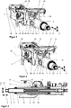
- FIG. 1 a perspective view of the steering column, wherein the locking element 15 is in the locked position, in which the shell unit 1 is detected on the console unit 4 in position.
- the locking element 15 is coupled to a stop body 8, wherein this stop body 8 has a stop surface 81.
- This abutment surface 81 is disengaged from the counter-abutment surface 9 formed on the jacket tube 1, so that the jacket unit 1 collapse without hindrance in the event of a collision or a crash. In other words, an energy reduction in the event of a collision due to this measure by the stopper body 8 is not disturbed or not burdened with additional undesirable force peaks.
- FIG. 1 further shows the console unit 4, which is fixable by means of the fastening tabs 16 on the vehicle, two side cheeks 30, between which the shell unit 1 and a box rocker 40 of the steering column is held.
- the steering spindle 2 is mounted rotatably about the steering spindle longitudinal axis 3.
- the locking mechanism in this embodiment is based essentially on frictional engagement. In the locking position of the locking element 15 according FIG. 1 the side cheeks 30 are pressed by the locking mechanism against the box rocker 40 and this in turn on shell unit 1, that these by means of frictional engagement in their position is held relative to the console unit 4.
- the steering wheel which is not shown here but which is mounted on the rear end 31 of the steering shaft 2 relative to the direction of travel of the vehicle, is fixed in its position. If there is a crash or a collision in this position and the vehicle driver is thrown onto the steering wheel, not shown here, the steering spindle 2 together with the jacket unit 1 is displaced relative to the console unit 4 in such a way that the rear end 31 of the steering spindle 2 in the direction of the console unit 4 moves. At the beginning of this displacement of the clamping unit 1 held clampingly in the console unit 4, the static friction must first be overcome in the exemplary embodiment shown. This can cause a peak load.
- the energy introduced by the loading of the steering wheel into the steering column is absorbed by the friction which has to be overcome when moving the shell unit 1 relative to the console unit 4, when the locking element 15 moves according to FIG FIG. 1 in the locked position.
- the stopper body 8 is arranged in the locking position of the locking element 15 so that it is not in the course of the displacement in engagement with the shell unit 1 and ., a counter-stop 9 on the jacket unit 1 passes.
- the steering column is additionally equipped with an energy absorption mechanism 90, which in the example comprises two intermeshing C-profiles, which consumes energy with friction on displacement of the shell unit 1 relative to the box rocker 40. Conceivable and possible is the use of other energy absorption devices, as they are known from the prior art.
- FIG. 2 shows the release position of the locking element 15 in a perspective view of the steering column, in which the shell unit 1 relative to the console unit 4 can be adjusted.
- this release position of the locking element 15 both an adjustment of the shell unit 1 in the direction 5 parallel to the steering spindle longitudinal axis 3, as well as in the directions 6 transverse to the steering spindle longitudinal axis 3 possible.
- the steering column is designed to be adjustable in the longitudinal direction 5 and in the height direction 6.
- the stopper 8 is compared to that in the FIG. 1 shown locking position pivots about the Feststellelementschwenkachse 14 so that it rests on the jacket unit 1 and according to the invention has an increased distance between the stop surface 81 and the locking element pivot axis 14.
- the stopper body 8 has been moved with the abutment surface 81 toward the counter-stopper 9.
- the stopper body 8 can thus be brought with its stop surface 81 in engagement with the counter-stop 9, when the jacket unit is fully inserted in the longitudinal adjustment.
- the stopper body 8 limited in cooperation with the counter-stop 9 the adjustment in the longitudinal direction of the shell unit 1 in the release position of the locking element.
- FIG. 3 shows a sectional view of the steering column from the FIGS. 1 along the steering spindle longitudinal axis 3. It can be seen that the steering column is in the locking position, since the stopper body 8 is out of engagement with the counter-stop 9 of the shell unit 1, so that a displacement of the shell unit 1 and the steering shaft 2 in the longitudinal direction not through an interaction of the stop surface 81 of the stopper body 8 and the counter-stop 9 is limited.
- the jacket unit 1 is located with respect to the longitudinal adjustment in a fully inserted state during normal operation, so that the intended Leksverstell Siemens GmbH is in its limit.
- FIG. 4 shows a detailed view of a sectional view of the steering column, wherein the locking element 15 and the steering column is in the locked position.
- the stop surface 81 of the stopper body is brought by appropriate rotation of the stopper body 8 with the locking element 15 about the locking element pivot axis 14 out of engagement with the counter-stop 9 of the shell unit 1.
- a displacement of the jacket unit 1 and the steering spindle 2 in the longitudinal direction is not limited by an interaction of the stop surface 81 of the stopper body 8 and the counter-stopper 9.
- the stopper 8 has a biasing member 83, wherein the biasing member 83 rests on the shell unit 1 and biases the stopper body 8 at a moment about the Festellelementschwenkachse 14 of the locking element in the direction of engagement.
- the stopper body 8 further comprises a control surface 82, which cooperates with a cam portion 71 on the Festellelement 15.
- the abutment surface 81 is spaced apart by the distance s to the Feststellelementeschwenkachse 14.
- the control surface 82 is relative to the locking element pivot axis 14 arranged in a first peripheral region of the recess 87, on the side where the abutment surface 81 is located on the stopper body 8, so in the drawing left of the Feststellelementschwenkachse fourteenth
- the stopper body 8 has a second control surface 89, which cooperates with a second cam portion 72 of the Festellelements 15.
- the second control surface 89 is arranged in a relative to the Feststellelementschwenkachse (14) opposite the second peripheral region, which is opposite to the first peripheral region, so in the drawing right of the Feststellelementschwenkachse fourteenth
- FIG. 5 shows a detailed view of a sectional view of the steering column, wherein the locking element 15 and the steering column is in a transfer state, also referred to as release position, between the locking position and the release position.
- the locking element 15 and the stopper body 8 was compared to the locking position of FIG. 4 pivoted about the locking element pivot axis 14 in the counterclockwise direction, wherein the stopper body 8 rests on the shell unit 1 and thus prevented from further rotation about the locking element pivot axis 14.
- the value of the distance s between the Feststellelementschwenkachse 14 and the stop surface 81 of the stopper body 8 is identical to distance s, in the locking position corresponding to the FIG. 4 , FIG.
- FIG. 6 shows a detailed view of a sectional view of the steering column, wherein the locking element 15 and the steering column is in the release position.
- the steering column is shown in a stop position with respect to the longitudinal adjustment.
- the jacket unit 1 is inserted completely in the longitudinal direction and is thus located at one end of the adjustment region, which is defined by the cooperation of the stop surface 81 of the stopper body 8 with the counter-stop 9.
- the locking element 15 was compared to the locking position according to FIG. 4 and the transfer state according to FIG. 5 further pivoted counterclockwise. Since the stopper body 8 already in the transfer state of FIG. 5 placed on the jacket tube and thus blocked against further pivoting counterclockwise, a relative pivoting of the locking member 15 relative to the stop body.
- the cam portion 71 slides over the control surface 82 of the stopper body 8 and pushes the stopper body 8 and thus the abutment surface 81 away from the Feststellelementschwenkachse 14 so that the stopper body 8 slides over the surface of the sheath unit 1 toward the counter-stopper 9.
- the jacket unit 1 can now be adjusted relative to the vehicle.
- the locking device 7 is in the locking position, starting from the illustration corresponding to FIG. 6 and continuing according to the representation of FIG. 5 in the state according to the representation of FIG. 4 transferred.
- the locking element 15 is pivoted in the clockwise direction.
- biasing means of the biasing member 83 is a reverse rotation of the stopper body 8 while reducing the distance s1 by the amount e between the Feststellelementschwenkachse 14 and the stop surface 81.
- the second cam portion is moved against the second control surface 89, wherein the stopper body 8 to the Amount e in the direction of the locking element pivot axis 14 is moved to.
- the jacket unit 1 can not be adjusted. If a new adjustment to be effected, the steering column is again transferred to the release position.
- the placement of the stopper body is excluded on the counter-stop by the inventive displacement of the stopper body 8. As a result, slipping of the stops can be prevented and accordingly the limitation of the adjustment can be ensured.
- FIG. 5 the so-called release position of the method according to the invention is shown, in which the stopper body 8 in comparison to the release position according to FIG. 6 is displaced translationally by the amount e in the direction of the steering spindle longitudinal axis 3.
- FIGS. 10 to 12 a stop member 180 known from the prior art is shown schematically, which cooperates with a counter-stop 190 to limit the adjustment of the shell unit 111.
- the rest of the steering column has an analog structure as in the FIGS. 1 to 3 illustrated steering column.
- the stopper body 180 is rotatably coupled to a locking member 170 and pivotable together with this locking member 170 to bring the stopper body 180 in a first position in which this cooperates with the counter-stop 190 to the To limit adjustment of the jacket unit 111 in the longitudinal adjustment direction and continue to transfer to a second position in which the stop member 190 is out of engagement with the counter-stop 190.
- the stop body 180 assumes the first position in the release position of the locking element 170 and, accordingly, the stop body 180 assumes the second position in the locking position of the locking element 180.
- the known from the prior art stop body 180 is shown schematically in a possible Verstellsituation.
- the stopper body 180 is shown in a first position, in which the adjustment of the shell unit 111 is limited in the longitudinal direction, wherein the stopper is completely reached.
- the jacket tube 111 is moved with the counter-stop 190 against the stop surface 181 of the stopper body 180, wherein the stopper body 180 is biased by the action of the driver, not shown, under bias, wherein the stopper body 180 has an elastic deformation 185, that is elastically compressed.
- the locking element 170 is rotated together with the stopper body 180 about the locking element pivot axis 114 in the direction CW or pivoted, as shown in FIG FIG. 11 is shown.
- the steering column has been transferred to the locking position, wherein the stopper body 180 has undergone an elastic spring back, after which it was disengaged from the counter-stop 190.
- the stopper body 180 Due to the elastic springback of the stopper body 180, the stopper body 180 experiences a spatial extension, ie the stopper surface 181 has moved away from the locking element pivot axis 114, so that upon rotation of the locking element 170 together with the stopper body in the direction CCW to rest the stopper body 170 can come to the counter-stroke 190, as it is in the FIG. 12 is shown schematically.
- FIG. 7 is a perspective view of the stopper element 8 from the FIGS. 1 to 6 shown.
- This stop element 8 comprises the stop surface 81 and a Coupling portion 88 having a recess 87 for receiving the locking element 15, said recess 87 has the control surface 82 for cooperation with the cam portion 71 of the locking element 15.
- the stop element 8 has the two biasing elements 83, which are designed in the form of a leaf spring. These leaf springs are spaced from each other and partially surrounded by a plastic, which forms the coupling portion 88 and the abutment surface 81, in order to achieve embedding of the biasing elements 83.
- the distance between the two biasing elements 83 is selected so that the counter-stop 9, which cooperates with the stop surface 81 in normal operation, can pass the stop element 8 in the event of a crash without hindrance. Accordingly, the counter-stop 9 can move in the event of a collision or crash between the biasing elements 83. Thus, it can be ensured that no additional force peak occurs by the passage of the counter-stop 9 during the collapse of the shell unit 1 in the event of a crash.
- FIG. 8 is a perspective view of an alternative embodiment of the stop element 8 is shown.
- This stop element 8 comprises the stop surface 81 and the coupling portion 88, which has a recess 87 for receiving the locking element 15, said recess 87 having the control surface 82 for cooperation with the cam portion 71 of the locking element 15.
- the stop element 8 has an eccentrically arranged biasing element 83, which are designed in the form of a leaf spring. This leaf spring is partially surrounded by a plastic, which forms the coupling portion 88 and the abutment surface 81, in order to achieve an embedding of the biasing member 83.
- the biasing element 83 is arranged so that the counter-stop 9, which cooperates with the stop surface 81 in normal operation, can pass the stop element 8 in the event of a crash without hindrance.
- FIG. 9 is a perspective view of another alternative embodiment of the stop element 8 is shown.
- This stop element 8 also includes the stop surface 81 and the coupling portion 88, which has a recess 87 for receiving the locking element 15.
- the recess 87 has the control surface 82 for cooperation with the cam portion 71 of the locking element 15.
- the stopper member 8 further comprises the biasing member 83, wherein the entire stopper member 8 is integrally formed of plastic.
- the stop element 8 can be represented from a single plastic in an injection molding process. However, it may be advantageous for the presentation of certain biases and the achievement of a high durability to use a multi-component plastic injection molding.
Landscapes
- Engineering & Computer Science (AREA)
- Chemical & Material Sciences (AREA)
- Combustion & Propulsion (AREA)
- Transportation (AREA)
- Mechanical Engineering (AREA)
- Steering Controls (AREA)
Claims (21)
- Colonne de direction pour un véhicule automobile comprenant une unité d'enveloppe (1) dans laquelle est supporté un arbre de direction (2) de manière à pouvoir tourner autour de son axe longitudinal d'arbre de direction (3) et une unité de console (4) fixée ou pouvant être fixée au véhicule automobile, l'unité d'enveloppe (1) étant retenue dans ou sur l'unité de console (4) de manière déplaçable dans au moins une direction (5, 6) parallèlement et/ou transversalement à l'axe longitudinal d'arbre de direction (3) et pouvant être fixée par un mécanisme de fixation dans des positions différentes les unes des autres, et le mécanisme de fixation (7) présentant au moins un élément de fixation (15) supporté de manière à pouvoir tourner autour d'un axe de pivotement d'élément de fixation (14), l'unité d'enveloppe (1), dans au moins une position de verrouillage de l'élément de fixation (15), étant fixée dans sa position dans ou sur l'unité de console (4) et dans au moins une position de libération de l'élément de fixation (15), l'unité d'enveloppe (1) pouvant être déplacée par rapport à l'unité de console (4) dans au moins l'une des directions parallèlement et/ou transversalement à l'axe longitudinal d'arbre de direction (3), la colonne de direction présentant au moins un corps de butée (8) supporté de manière déplaçable et coopérant directement ou indirectement avec l'élément de fixation (15), lequel corps de butée, dans la position de libération de l'élément de fixation (15), est disposé dans une première position dans laquelle il la capacité de déplacement de l'unité d'enveloppe (1) par rapport à l'unité de console (4) est limitée dans au moins l'une des directions (5, 6) parallèlement et/ou transversalement à l'axe longitudinal d'arbre de direction (3), et dans la position de verrouillage de l'élément de fixation (15), est disposé dans au moins une deuxième position dans laquelle il est hors d'engagement avec l'unité d'enveloppe (1),
caractérisée en ce que
le corps de butée (8) présente une surface de butée (81) dont la distance (s) à l'axe de pivotement de l'élément de fixation (14) est plus grande dans la position de libération que dans la position de verrouillage. - Colonne de direction selon la revendication 1, caractérisée en ce que la colonne de direction présente au moins une contre-butée (9), la surface de butée (81) du corps de butée (8), dans la position de libération de l'élément de fixation (15), coopérant avec la contre-butée (9) pour limiter la capacité de déplacement de l'unité d'enveloppe (1) par rapport à l'unité de console (4) dans au moins l'une des directions (5, 6) parallèlement et/ou transversalement à l'axe longitudinal d'arbre de direction (3).
- Colonne de direction selon l'une quelconque des revendications précédentes, caractérisée en ce que le corps de butée (8) peut tourner autour de l'axe de pivotement d'élément de fixation (14).
- Colonne de direction selon la revendication 1, caractérisée en ce que l'élément de fixation (15) comprend une came ou une portion de came (71), cette came ou cette portion de came (71) coopérant avec une surface de commande (82) du corps de butée (8).
- Colonne de direction selon l'une quelconque des revendications précédentes, caractérisée en ce qu'un élément de précontrainte, par exemple sous la forme d'une langue de ressort (83), est prévu, lequel est accouplé au corps de butée (8) par un élément de précontrainte ou présente un élément de précontrainte (83).
- Colonne de direction selon l'une quelconque des revendications précédentes, caractérisée en ce que le corps de butée (8) se compose au moins en partie d'un plastique.
- Colonne de direction selon l'une quelconque des revendications précédentes, caractérisée en ce que le corps de butée (8), pendant le transfert de la position de verrouillage dans la position de libération et/ou pendant le transfert de la position de libération dans la position de verrouillage, s'effectue un déplacement dans la direction de l'axe longitudinal d'arbre de direction (3).
- Colonne de direction selon l'une quelconque des revendications précédentes, caractérisée en ce que la différence (e) entre la distance (s1) dans la position de libération et la distance (s) dans la position de verrouillage présente une valeur comprise entre 0,2 mm et 5 mm.
- Corps de butée (8) de la colonne de direction selon la revendication 1, comprenant une portion de couplage (88) pour recevoir un élément de fixation (15) d'une colonne de direction, et au moins une surface de butée (81) destinée à coopérer avec une contre-butée (9) de la colonne de direction, caractérisé en ce que la portion de couplage (84) comprend une surface de commande (82) pour coopérer avec une portion de came (71) au niveau de l'élément de fixation (15).
- Corps de butée (8) selon la revendication 9, caractérisé en ce que la surface de commande (82) est disposée tangentiellement à un cercle périphérique autour de la portion de came (71) de l'élément de fixation (15).
- Corps de butée (8) selon la revendication 9, caractérisé en ce que la surface de commande (82) est orientée parallèlement à l'axe de pivotement d'élément de fixation (14) et la surface de butée (81) est orientée parallèlement à l'axe de pivotement d'élément de fixation (14), les directions normales à la surface de commande (82) et à la surface de butée (81) ayant une composante vectorielle commune.
- Corps de butée (8) selon la revendication 9, caractérisé en ce que dans l'état installé, la portion de couplage (88) avec un évidement (87) entoure au moins en partie l'élément de fixation (15) avec un espace intermédiaire.
- Corps de butée (8) selon la revendication 12, caractérisé en ce que la surface de commande (82) est réalisée sur une surface intérieure de l'évidement (87) de la portion de couplage (88).
- Corps de butée (8) selon la revendication 12, caractérisé en ce qu'au moins une surface de commande (82, 89) est réalisée sous forme de portion tangentielle, plane, de la paroi intérieure de l'évidement (87).
- Corps de butée (8) selon la revendication 12, caractérisé en ce que l'évidement (87) présente au moins une première région périphérique intérieure réalisée sous forme de surface de commande (82, 89) et une deuxième région périphérique intérieure réalisée, par rapport à celle-ci, à une plus grande distance de l'axe de pivotement d'élément de fixation (14).
- Corps de butée (8) selon la revendication 12, caractérisé en ce que le corps de butée présente une première surface de commande (82) et une deuxième surface de commande (89), la première surface de commande (82) étant disposée, par rapport à l'axe de pivotement d'élément de fixation (14), dans une première région périphérique de l'évidement (87), du côté où se trouve la surface de butée (81) sur le corps de butée (8) et la deuxième surface de commande (89) étant disposée dans une deuxième région périphérique opposée par rapport à l'axe de pivotement d'élément de fixation (14).
- Corps de butée (8) selon la revendication 12, caractérisé en ce que l'évidement (87) présente une section transversale polygonale, de préférence rectangulaire.
- Corps de butée (8) selon la revendication 9, caractérisé en ce qu'un élément de précontrainte (83) est monté sur le corps de butée (83).
- Corps de butée (8) selon la revendication 18, caractérisé en ce que l'élément de précontrainte (83) est réalisé sous forme de langue de ressort (83) qui, vue depuis la portion de couplage (88), s'étend jusqu'à un côté opposé à la surface de butée (81).
- Procédé de réglage d'une colonne de direction pour un véhicule automobile, une unité d'enveloppe (1), dans laquelle est supporté un arbre de direction (2) de manière à pouvoir tourner autour de son axe longitudinal d'arbre de direction (3), étant déplacée par rapport à une unité de console (4) fixée ou pouvant être fixée au véhicule automobile, l'unité d'enveloppe (1) étant retenue dans ou sur l'unité de console (4) de manière déplaçable dans au moins une direction (5, 6) parallèlement et/ou transversalement à l'axe longitudinal d'arbre de direction (3) et pouvant être fixée par un mécanisme de fixation dans des positions différentes les unes des autres et le mécanisme de fixation (7) présentant au moins un élément de fixation (15) supporté de manière à pouvoir tourner autour d'un axe de pivotement de l'élément de fixation (14), l'unité d'enveloppe (1), dans au moins une position de verrouillage de l'élément de fixation (15), étant fixée dans sa position dans ou sur l'unité de console (4), et dans au moins une position de libération de l'élément de fixation (15), l'unité d'enveloppe (1) pouvant être déplacée par rapport à l'unité de console (4) dans au moins l'une des directions parallèlement et/ou transversalement à l'axe longitudinal d'arbre de direction (3), la colonne de direction présentant au moins un corps de butée (8) avec une surface de butée (81), supporté de manière déplaçable et coopérant directement ou indirectement avec l'élément de fixation (15), lequel corps de butée, dans la position de libération de l'élément de fixation (15), est disposé dans une première position dans laquelle il la capacité de déplacement de l'unité d'enveloppe (1) par rapport à l'unité de console (4) est limitée dans au moins l'une des directions (5, 6) parallèlement et/ou transversalement à l'axe longitudinal d'arbre de direction (3), et dans la position de verrouillage de l'élément de fixation (15), est disposé dans au moins une deuxième position dans laquelle il est hors d'engagement avec l'unité d'enveloppe (1),
caractérisé en ce que
le corps de butée (8) est amené entre la position de libération et la position de verrouillage dans une position de desserrage, la surface de butée (81) du corps de butée (8) étant déplacée de la position de libération dans la direction de l'axe longitudinal d'arbre de direction (3) en translation vers l'axe de pivotement d'élément de fixation (14). - Procédé de réglage d'une colonne de direction pour un véhicule automobile, une unité d'enveloppe (1), dans laquelle est supporté un arbre de direction (2) de manière à pouvoir tourner autour de son axe longitudinal d'arbre de direction (3), étant déplacée par rapport à une unité de console (4) fixée ou pouvant être fixée au véhicule automobile, l'unité d'enveloppe (1) étant retenue dans ou sur l'unité de console (4) de manière déplaçable dans au moins une direction (5, 6) parallèlement et/ou transversalement à l'axe longitudinal d'arbre de direction (3) et pouvant être fixée par un mécanisme de fixation dans des positions différentes les unes des autres et le mécanisme de fixation (7) présentant au moins un élément de fixation (15) supporté de manière à pouvoir tourner autour d'un axe de pivotement d'élément de fixation (14), l'unité d'enveloppe (1), dans au moins une position de verrouillage de l'élément de fixation (15), étant fixée dans sa position dans ou sur l'unité de console (4), et dans au moins une position de libération de l'élément de fixation (15), l'unité d'enveloppe (1) pouvant être déplacée par rapport à l'unité de console (4) dans au moins l'une des directions parallèlement et/ou transversalement à l'axe longitudinal d'arbre de direction (3), la colonne de direction présentant au moins un corps de butée (8) avec une surface de butée (81), supporté de manière déplaçable et coopérant directement ou indirectement avec l'élément de fixation (15), lequel corps de butée, dans la position de libération de l'élément de fixation (15), est disposé dans une première position dans laquelle il la capacité de déplacement de l'unité d'enveloppe (1) par rapport à l'unité de console (4) est limitée dans au moins l'une des directions (5, 6) parallèlement et/ou transversalement à l'axe longitudinal d'arbre de direction (3), et dans la position de verrouillage de l'élément de fixation (15), est disposé dans au moins une deuxième position dans laquelle il est hors d'engagement avec l'unité d'enveloppe (1),
caractérisé en ce que
le corps de butée (8) est amené entre la position de verrouillage et la position de libération dans une position de desserrage, la surface de butée (81) du corps de butée (8) étant déplacée de la position de verrouillage dans la direction de l'axe longitudinal d'arbre de direction (3) en translation à l'écart de l'axe de pivotement d'élément de fixation (14).
Priority Applications (1)
| Application Number | Priority Date | Filing Date | Title |
|---|---|---|---|
| PL15766532T PL3218246T3 (pl) | 2014-11-10 | 2015-09-22 | Kolumna kierownicy z ogranicznikiem wzdłużnym z regulowaną funkcją zwolnienia w przypadku kolizji |
Applications Claiming Priority (2)
| Application Number | Priority Date | Filing Date | Title |
|---|---|---|---|
| DE102014016510.8A DE102014016510B4 (de) | 2014-11-10 | 2014-11-10 | Lenksäule mit Längsanschlag mit einstellbarer Freigabefunktion für Crash |
| PCT/EP2015/071729 WO2016074838A1 (fr) | 2014-11-10 | 2015-09-22 | Colonne de direction comportant une butée longitudinale présentant une fonction de libération en cas d'accident |
Publications (2)
| Publication Number | Publication Date |
|---|---|
| EP3218246A1 EP3218246A1 (fr) | 2017-09-20 |
| EP3218246B1 true EP3218246B1 (fr) | 2019-02-20 |
Family
ID=52446891
Family Applications (1)
| Application Number | Title | Priority Date | Filing Date |
|---|---|---|---|
| EP15766532.4A Active EP3218246B1 (fr) | 2014-11-10 | 2015-09-22 | Colonne de direction comportant une butée longitudinale présentant une fonction de libération en cas d'accident |
Country Status (7)
| Country | Link |
|---|---|
| US (1) | US10308275B2 (fr) |
| EP (1) | EP3218246B1 (fr) |
| CN (1) | CN107207032B (fr) |
| DE (1) | DE102014016510B4 (fr) |
| ES (1) | ES2724983T3 (fr) |
| PL (1) | PL3218246T3 (fr) |
| WO (1) | WO2016074838A1 (fr) |
Cited By (1)
| Publication number | Priority date | Publication date | Assignee | Title |
|---|---|---|---|---|
| US12162530B2 (en) | 2022-06-30 | 2024-12-10 | Thyssenkrupp Presta Ag | Steering column for a motor vehicle |
Families Citing this family (20)
| Publication number | Priority date | Publication date | Assignee | Title |
|---|---|---|---|---|
| DE102015209060B4 (de) | 2015-05-18 | 2016-12-01 | Thyssenkrupp Ag | Lenksäule für ein Kraftfahrzeug und Energieabsorptionseinrichtung |
| DE102015007784B4 (de) | 2015-06-19 | 2020-02-13 | Thyssenkrupp Ag | Lenksäule mit elektro-mechanischer Fixiervorrichtung |
| DE102015216326B4 (de) | 2015-08-26 | 2016-09-08 | Thyssenkrupp Ag | Motorisch verstellbare Lenksäule für ein Kraftfahrzeug |
| DE102015216536B3 (de) * | 2015-08-28 | 2017-02-16 | Thyssenkrupp Ag | Klemmvorrichtung einer verstellbaren Lenksäule für Kraftfahrzeuge |
| DE102015216715A1 (de) | 2015-09-01 | 2017-03-02 | Thyssenkrupp Ag | Verstellbare Lenksäule für Kraftfahrzeuge mit Energieabsorber für den Fahrzeugcrash |
| DE102015217761B3 (de) | 2015-09-16 | 2016-10-13 | Thyssenkrupp Ag | Lenksäule für Kraftfahrzeuge mit Energieabsorber für den Crashfall |
| DE102015225907A1 (de) | 2015-12-18 | 2017-06-22 | Thyssenkrupp Ag | Lenksäule für ein Kraftfahrzeug |
| DE102016000635A1 (de) * | 2016-01-25 | 2017-07-27 | Thyssenkrupp Ag | Lenksäule mit elektrischer Lenkungsverriegelung |
| DE102016210833A1 (de) | 2016-06-17 | 2017-12-21 | Thyssenkrupp Ag | Lenksäule für ein Kraftfahrzeug |
| JP6697336B2 (ja) * | 2016-06-30 | 2020-05-20 | 株式会社山田製作所 | ステアリング装置 |
| DE102016218271A1 (de) | 2016-09-22 | 2018-03-22 | Thyssenkrupp Ag | Manteleinheit für eine verstellbare Lenksäule eines Kraftfahrzeugs |
| US10286945B2 (en) * | 2017-10-05 | 2019-05-14 | Thyssenkrupp Ag | Adjustable steering column assembly |
| DE102017126705A1 (de) * | 2017-11-14 | 2019-05-16 | Thyssenkrupp Ag | Lenksäule für ein Kraftfahrzeug |
| FR3075151B1 (fr) * | 2017-12-15 | 2020-01-10 | Robert Bosch Automotive Steering Vendome | Colonne de direction a butee de fin de course de reglage |
| DE102017130358A1 (de) * | 2017-12-18 | 2019-06-19 | Trw Automotive Gmbh | Lenksäulenbaugruppe |
| KR102398780B1 (ko) * | 2018-03-28 | 2022-05-17 | 남양넥스모 주식회사 | 스티어링 칼럼 |
| DE102018208745B4 (de) * | 2018-06-04 | 2026-02-12 | Audi Ag | Lenkwelle für eine Lenkung eines Kraftwagens, Lenkung für einen Kraftwagen sowie Kraftwagen |
| DE102018211046B3 (de) | 2018-07-04 | 2019-08-29 | Thyssenkrupp Ag | Verfahren zur Einstellung der Betätigungskraft zur Fixierung einer verstellbaren Lenksäule |
| DE102019205861A1 (de) * | 2019-04-24 | 2020-10-29 | Thyssenkrupp Ag | Lenksäule für ein Kraftfahrzeug |
| JP7890859B2 (ja) * | 2022-05-16 | 2026-07-15 | Nskステアリング&コントロール株式会社 | ステアリング装置 |
Family Cites Families (24)
| Publication number | Priority date | Publication date | Assignee | Title |
|---|---|---|---|---|
| US6139057A (en) * | 1999-02-04 | 2000-10-31 | Delphi Technologies, Inc. | Position control apparatus for steering column |
| US6419269B1 (en) * | 1999-09-20 | 2002-07-16 | Delphi Technologies | Locking system for adjustable position steering column |
| US7021660B2 (en) | 2002-09-30 | 2006-04-04 | Nsk Steering Systems America, Inc. | Adjustable steering column for motor vehicles |
| JP2005001517A (ja) | 2003-06-12 | 2005-01-06 | Nsk Ltd | ステアリング装置 |
| US7484430B2 (en) * | 2004-07-27 | 2009-02-03 | Delphi Technologies, Inc. | Telescope feature used for energy absorption |
| JP4882127B2 (ja) | 2005-11-16 | 2012-02-22 | 株式会社ジェイテクト | 位置調整式ステアリング装置 |
| FR2915950B1 (fr) * | 2007-05-11 | 2009-07-03 | Zf Systemes De Direction Nacam Sas | Dispositif de maintien en position a absorption d'energie d'une colonne de direction de vehicule automobile |
| GB0721238D0 (en) * | 2007-10-30 | 2007-12-05 | Trw Ltd | Steering column assembly |
| US8037782B2 (en) | 2007-10-31 | 2011-10-18 | Fuji Kiko Co., Ltd. | Steering column assembly |
| JP4985443B2 (ja) | 2008-02-12 | 2012-07-25 | トヨタ自動車株式会社 | ステアリングコラム装置 |
| JP5229078B2 (ja) | 2009-04-08 | 2013-07-03 | トヨタ自動車株式会社 | ステアリングコラム装置 |
| WO2010122958A1 (fr) * | 2009-04-20 | 2010-10-28 | 日本精工株式会社 | Dispositif de réglage de position pour volant de direction |
| DE102009055973B3 (de) | 2009-11-27 | 2011-06-16 | Thyssenkrupp Presta Ag | Lenksäule für ein Kraftfahrzeug |
| FR2958614B1 (fr) | 2010-04-13 | 2012-03-16 | Jtekt Europe Sas | Mecanisme de reglage d'une colonne de direction de vehicule automobile |
| DE102010036891A1 (de) | 2010-06-28 | 2011-12-29 | Thyssenkrupp Presta Ag | Verstellbare Lenksäule für ein Kraftfahrzeug |
| JP5333378B2 (ja) * | 2010-08-17 | 2013-11-06 | 日本精工株式会社 | ステアリング装置 |
| US8783717B2 (en) * | 2010-11-23 | 2014-07-22 | Steering Solutions Ip Holding Corporation | Steering column telescope lock |
| DE102011000319B3 (de) * | 2011-01-25 | 2012-05-24 | Thyssenkrupp Presta Ag | Feststelleinrichtung zum Feststellen einer Lenkspindellagereinheit |
| DE102011056351A1 (de) | 2011-12-13 | 2013-06-13 | Zf Lenksysteme Gmbh | Anschlag für verstellbare Lenksäule |
| CN202754011U (zh) * | 2012-06-29 | 2013-02-27 | 浙江吉利汽车研究院有限公司杭州分公司 | 转向管柱调节机构 |
| US8888131B2 (en) * | 2012-06-29 | 2014-11-18 | Steering Solutions Ip Holding Corporation | Position lock for steering column |
| US8657338B2 (en) * | 2012-06-29 | 2014-02-25 | Steering Solutions Ip Holding Corporation | Position lock for steering column |
| JP6351009B2 (ja) * | 2014-03-24 | 2018-07-04 | 株式会社ジェイテクト | ステアリング装置 |
| WO2015156055A1 (fr) * | 2014-04-11 | 2015-10-15 | 日本精工株式会社 | Dispositif de direction |
-
2014
- 2014-11-10 DE DE102014016510.8A patent/DE102014016510B4/de not_active Expired - Fee Related
-
2015
- 2015-09-22 US US15/521,731 patent/US10308275B2/en active Active
- 2015-09-22 EP EP15766532.4A patent/EP3218246B1/fr active Active
- 2015-09-22 CN CN201580061107.XA patent/CN107207032B/zh active Active
- 2015-09-22 ES ES15766532T patent/ES2724983T3/es active Active
- 2015-09-22 PL PL15766532T patent/PL3218246T3/pl unknown
- 2015-09-22 WO PCT/EP2015/071729 patent/WO2016074838A1/fr not_active Ceased
Non-Patent Citations (1)
| Title |
|---|
| None * |
Cited By (1)
| Publication number | Priority date | Publication date | Assignee | Title |
|---|---|---|---|---|
| US12162530B2 (en) | 2022-06-30 | 2024-12-10 | Thyssenkrupp Presta Ag | Steering column for a motor vehicle |
Also Published As
| Publication number | Publication date |
|---|---|
| WO2016074838A1 (fr) | 2016-05-19 |
| PL3218246T3 (pl) | 2019-08-30 |
| EP3218246A1 (fr) | 2017-09-20 |
| US20170247046A1 (en) | 2017-08-31 |
| CN107207032B (zh) | 2019-09-17 |
| CN107207032A (zh) | 2017-09-26 |
| DE102014016510A1 (de) | 2015-02-26 |
| US10308275B2 (en) | 2019-06-04 |
| DE102014016510B4 (de) | 2016-02-18 |
| ES2724983T3 (es) | 2019-09-18 |
Similar Documents
| Publication | Publication Date | Title |
|---|---|---|
| DE102014016510B4 (de) | Lenksäule mit Längsanschlag mit einstellbarer Freigabefunktion für Crash | |
| EP2504219B1 (fr) | Colonne de direction pour un véhicule à moteur | |
| EP2107983B1 (fr) | Colonne de direction avec dispositif de protection contre les collisions | |
| DE102014111606B3 (de) | Lenksäule für ein Kraftfahrzeug | |
| EP3271234B1 (fr) | Colonne de direction pour un véhicule automobile | |
| DE102015225488B3 (de) | Verstellbare Lenksäule für Kraftfahrzeuge mit Energieabsorptionsvorrichtung | |
| EP3353040B1 (fr) | Colonne de direction réglable pour véhicule automobile | |
| EP2900540B1 (fr) | Colonne de direction pour véhicule automobile | |
| EP3044071B1 (fr) | Système pourvu d'au moins un corps élastique et d'au moins un élément de blocage formé séparément | |
| WO2018073304A1 (fr) | Colonne de direction à dispositif d'absorption d'énergie adaptatif pour un véhicule à moteur | |
| DE102018125045A1 (de) | Lenksäule für fahrzeug | |
| WO2018073306A1 (fr) | Colonne de direction à dispositif d'absorption d'énergie pour un véhicule à moteur | |
| EP3436329B1 (fr) | Colonne de direction pour véhicule automobile | |
| EP3609770B1 (fr) | Colonne de direction comprenant un dispositif d'absorption d'énergie pour un véhicule à moteur | |
| EP3710334B1 (fr) | Colonne de direction pour un véhicule automobile | |
| DE102016106496A1 (de) | Antriebsanordnung einer Klappenanordnung eines Kraftfahrzeugs | |
| WO2009106257A1 (fr) | Colonne de direction réglable pour une automobile | |
| WO2012139622A2 (fr) | Agencement de colonne de direction | |
| DE102016202266A1 (de) | Kugelgewindetrieb mit Selbsthemmung | |
| DE102014108321A1 (de) | Lenksäule für ein Kraftfahrzeug | |
| DE102007058636A1 (de) | Sicherheitsgurtaufroller mit einer stufenlosen, sich selbsttätig einstellenden Kraftbegrenzungseinrichtung |
Legal Events
| Date | Code | Title | Description |
|---|---|---|---|
| STAA | Information on the status of an ep patent application or granted ep patent |
Free format text: STATUS: THE INTERNATIONAL PUBLICATION HAS BEEN MADE |
|
| PUAI | Public reference made under article 153(3) epc to a published international application that has entered the european phase |
Free format text: ORIGINAL CODE: 0009012 |
|
| STAA | Information on the status of an ep patent application or granted ep patent |
Free format text: STATUS: REQUEST FOR EXAMINATION WAS MADE |
|
| 17P | Request for examination filed |
Effective date: 20170529 |
|
| AK | Designated contracting states |
Kind code of ref document: A1 Designated state(s): AL AT BE BG CH CY CZ DE DK EE ES FI FR GB GR HR HU IE IS IT LI LT LU LV MC MK MT NL NO PL PT RO RS SE SI SK SM TR |
|
| AX | Request for extension of the european patent |
Extension state: BA ME |
|
| RAP1 | Party data changed (applicant data changed or rights of an application transferred) |
Owner name: THYSSENKRUPP PRESTA AG Owner name: THYSSENKRUPP AG |
|
| DAV | Request for validation of the european patent (deleted) | ||
| DAX | Request for extension of the european patent (deleted) | ||
| GRAP | Despatch of communication of intention to grant a patent |
Free format text: ORIGINAL CODE: EPIDOSNIGR1 |
|
| STAA | Information on the status of an ep patent application or granted ep patent |
Free format text: STATUS: GRANT OF PATENT IS INTENDED |
|
| INTG | Intention to grant announced |
Effective date: 20180829 |
|
| GRAS | Grant fee paid |
Free format text: ORIGINAL CODE: EPIDOSNIGR3 |
|
| GRAA | (expected) grant |
Free format text: ORIGINAL CODE: 0009210 |
|
| STAA | Information on the status of an ep patent application or granted ep patent |
Free format text: STATUS: THE PATENT HAS BEEN GRANTED |
|
| AK | Designated contracting states |
Kind code of ref document: B1 Designated state(s): AL AT BE BG CH CY CZ DE DK EE ES FI FR GB GR HR HU IE IS IT LI LT LU LV MC MK MT NL NO PL PT RO RS SE SI SK SM TR |
|
| REG | Reference to a national code |
Ref country code: GB Ref legal event code: FG4D Free format text: NOT ENGLISH |
|
| REG | Reference to a national code |
Ref country code: CH Ref legal event code: EP |
|
| REG | Reference to a national code |
Ref country code: AT Ref legal event code: REF Ref document number: 1097787 Country of ref document: AT Kind code of ref document: T Effective date: 20190315 |
|
| REG | Reference to a national code |
Ref country code: IE Ref legal event code: FG4D Free format text: LANGUAGE OF EP DOCUMENT: GERMAN |
|
| REG | Reference to a national code |
Ref country code: DE Ref legal event code: R096 Ref document number: 502015008032 Country of ref document: DE |
|
| REG | Reference to a national code |
Ref country code: LT Ref legal event code: MG4D |
|
| REG | Reference to a national code |
Ref country code: NL Ref legal event code: MP Effective date: 20190220 |
|
| PG25 | Lapsed in a contracting state [announced via postgrant information from national office to epo] |
Ref country code: PT Free format text: LAPSE BECAUSE OF FAILURE TO SUBMIT A TRANSLATION OF THE DESCRIPTION OR TO PAY THE FEE WITHIN THE PRESCRIBED TIME-LIMIT Effective date: 20190620 Ref country code: LT Free format text: LAPSE BECAUSE OF FAILURE TO SUBMIT A TRANSLATION OF THE DESCRIPTION OR TO PAY THE FEE WITHIN THE PRESCRIBED TIME-LIMIT Effective date: 20190220 Ref country code: FI Free format text: LAPSE BECAUSE OF FAILURE TO SUBMIT A TRANSLATION OF THE DESCRIPTION OR TO PAY THE FEE WITHIN THE PRESCRIBED TIME-LIMIT Effective date: 20190220 Ref country code: SE Free format text: LAPSE BECAUSE OF FAILURE TO SUBMIT A TRANSLATION OF THE DESCRIPTION OR TO PAY THE FEE WITHIN THE PRESCRIBED TIME-LIMIT Effective date: 20190220 Ref country code: NO Free format text: LAPSE BECAUSE OF FAILURE TO SUBMIT A TRANSLATION OF THE DESCRIPTION OR TO PAY THE FEE WITHIN THE PRESCRIBED TIME-LIMIT Effective date: 20190520 |
|
| PG25 | Lapsed in a contracting state [announced via postgrant information from national office to epo] |
Ref country code: BG Free format text: LAPSE BECAUSE OF FAILURE TO SUBMIT A TRANSLATION OF THE DESCRIPTION OR TO PAY THE FEE WITHIN THE PRESCRIBED TIME-LIMIT Effective date: 20190520 Ref country code: RS Free format text: LAPSE BECAUSE OF FAILURE TO SUBMIT A TRANSLATION OF THE DESCRIPTION OR TO PAY THE FEE WITHIN THE PRESCRIBED TIME-LIMIT Effective date: 20190220 Ref country code: IS Free format text: LAPSE BECAUSE OF FAILURE TO SUBMIT A TRANSLATION OF THE DESCRIPTION OR TO PAY THE FEE WITHIN THE PRESCRIBED TIME-LIMIT Effective date: 20190620 Ref country code: HR Free format text: LAPSE BECAUSE OF FAILURE TO SUBMIT A TRANSLATION OF THE DESCRIPTION OR TO PAY THE FEE WITHIN THE PRESCRIBED TIME-LIMIT Effective date: 20190220 Ref country code: LV Free format text: LAPSE BECAUSE OF FAILURE TO SUBMIT A TRANSLATION OF THE DESCRIPTION OR TO PAY THE FEE WITHIN THE PRESCRIBED TIME-LIMIT Effective date: 20190220 Ref country code: GR Free format text: LAPSE BECAUSE OF FAILURE TO SUBMIT A TRANSLATION OF THE DESCRIPTION OR TO PAY THE FEE WITHIN THE PRESCRIBED TIME-LIMIT Effective date: 20190521 Ref country code: NL Free format text: LAPSE BECAUSE OF FAILURE TO SUBMIT A TRANSLATION OF THE DESCRIPTION OR TO PAY THE FEE WITHIN THE PRESCRIBED TIME-LIMIT Effective date: 20190220 |
|
| REG | Reference to a national code |
Ref country code: ES Ref legal event code: FG2A Ref document number: 2724983 Country of ref document: ES Kind code of ref document: T3 Effective date: 20190918 |
|
| PG25 | Lapsed in a contracting state [announced via postgrant information from national office to epo] |
Ref country code: SK Free format text: LAPSE BECAUSE OF FAILURE TO SUBMIT A TRANSLATION OF THE DESCRIPTION OR TO PAY THE FEE WITHIN THE PRESCRIBED TIME-LIMIT Effective date: 20190220 Ref country code: RO Free format text: LAPSE BECAUSE OF FAILURE TO SUBMIT A TRANSLATION OF THE DESCRIPTION OR TO PAY THE FEE WITHIN THE PRESCRIBED TIME-LIMIT Effective date: 20190220 Ref country code: EE Free format text: LAPSE BECAUSE OF FAILURE TO SUBMIT A TRANSLATION OF THE DESCRIPTION OR TO PAY THE FEE WITHIN THE PRESCRIBED TIME-LIMIT Effective date: 20190220 Ref country code: AL Free format text: LAPSE BECAUSE OF FAILURE TO SUBMIT A TRANSLATION OF THE DESCRIPTION OR TO PAY THE FEE WITHIN THE PRESCRIBED TIME-LIMIT Effective date: 20190220 Ref country code: DK Free format text: LAPSE BECAUSE OF FAILURE TO SUBMIT A TRANSLATION OF THE DESCRIPTION OR TO PAY THE FEE WITHIN THE PRESCRIBED TIME-LIMIT Effective date: 20190220 |
|
| REG | Reference to a national code |
Ref country code: DE Ref legal event code: R097 Ref document number: 502015008032 Country of ref document: DE |
|
| PG25 | Lapsed in a contracting state [announced via postgrant information from national office to epo] |
Ref country code: SM Free format text: LAPSE BECAUSE OF FAILURE TO SUBMIT A TRANSLATION OF THE DESCRIPTION OR TO PAY THE FEE WITHIN THE PRESCRIBED TIME-LIMIT Effective date: 20190220 |
|
| PLBE | No opposition filed within time limit |
Free format text: ORIGINAL CODE: 0009261 |
|
| STAA | Information on the status of an ep patent application or granted ep patent |
Free format text: STATUS: NO OPPOSITION FILED WITHIN TIME LIMIT |
|
| 26N | No opposition filed |
Effective date: 20191121 |
|
| PG25 | Lapsed in a contracting state [announced via postgrant information from national office to epo] |
Ref country code: SI Free format text: LAPSE BECAUSE OF FAILURE TO SUBMIT A TRANSLATION OF THE DESCRIPTION OR TO PAY THE FEE WITHIN THE PRESCRIBED TIME-LIMIT Effective date: 20190220 |
|
| PG25 | Lapsed in a contracting state [announced via postgrant information from national office to epo] |
Ref country code: TR Free format text: LAPSE BECAUSE OF FAILURE TO SUBMIT A TRANSLATION OF THE DESCRIPTION OR TO PAY THE FEE WITHIN THE PRESCRIBED TIME-LIMIT Effective date: 20190220 |
|
| PG25 | Lapsed in a contracting state [announced via postgrant information from national office to epo] |
Ref country code: MC Free format text: LAPSE BECAUSE OF FAILURE TO SUBMIT A TRANSLATION OF THE DESCRIPTION OR TO PAY THE FEE WITHIN THE PRESCRIBED TIME-LIMIT Effective date: 20190220 |
|
| REG | Reference to a national code |
Ref country code: CH Ref legal event code: PL |
|
| PG25 | Lapsed in a contracting state [announced via postgrant information from national office to epo] |
Ref country code: LU Free format text: LAPSE BECAUSE OF NON-PAYMENT OF DUE FEES Effective date: 20190922 Ref country code: CH Free format text: LAPSE BECAUSE OF NON-PAYMENT OF DUE FEES Effective date: 20190930 Ref country code: IE Free format text: LAPSE BECAUSE OF NON-PAYMENT OF DUE FEES Effective date: 20190922 Ref country code: LI Free format text: LAPSE BECAUSE OF NON-PAYMENT OF DUE FEES Effective date: 20190930 |
|
| REG | Reference to a national code |
Ref country code: BE Ref legal event code: MM Effective date: 20190930 |
|
| PG25 | Lapsed in a contracting state [announced via postgrant information from national office to epo] |
Ref country code: BE Free format text: LAPSE BECAUSE OF NON-PAYMENT OF DUE FEES Effective date: 20190930 |
|
| PG25 | Lapsed in a contracting state [announced via postgrant information from national office to epo] |
Ref country code: CY Free format text: LAPSE BECAUSE OF FAILURE TO SUBMIT A TRANSLATION OF THE DESCRIPTION OR TO PAY THE FEE WITHIN THE PRESCRIBED TIME-LIMIT Effective date: 20190220 |
|
| PG25 | Lapsed in a contracting state [announced via postgrant information from national office to epo] |
Ref country code: HU Free format text: LAPSE BECAUSE OF FAILURE TO SUBMIT A TRANSLATION OF THE DESCRIPTION OR TO PAY THE FEE WITHIN THE PRESCRIBED TIME-LIMIT; INVALID AB INITIO Effective date: 20150922 Ref country code: MT Free format text: LAPSE BECAUSE OF FAILURE TO SUBMIT A TRANSLATION OF THE DESCRIPTION OR TO PAY THE FEE WITHIN THE PRESCRIBED TIME-LIMIT Effective date: 20190220 |
|
| REG | Reference to a national code |
Ref country code: DE Ref legal event code: R081 Ref document number: 502015008032 Country of ref document: DE Owner name: THYSSENKRUPP PRESTA AKTIENGESELLSCHAFT, LI Free format text: FORMER OWNERS: THYSSENKRUPP AG, 45143 ESSEN, DE; THYSSENKRUPP PRESTA AG, ESCHEN, LI Ref country code: DE Ref legal event code: R081 Ref document number: 502015008032 Country of ref document: DE Owner name: THYSSENKRUPP AG, DE Free format text: FORMER OWNERS: THYSSENKRUPP AG, 45143 ESSEN, DE; THYSSENKRUPP PRESTA AG, ESCHEN, LI |
|
| REG | Reference to a national code |
Ref country code: AT Ref legal event code: MM01 Ref document number: 1097787 Country of ref document: AT Kind code of ref document: T Effective date: 20200922 |
|
| PG25 | Lapsed in a contracting state [announced via postgrant information from national office to epo] |
Ref country code: AT Free format text: LAPSE BECAUSE OF NON-PAYMENT OF DUE FEES Effective date: 20200922 |
|
| PG25 | Lapsed in a contracting state [announced via postgrant information from national office to epo] |
Ref country code: MK Free format text: LAPSE BECAUSE OF FAILURE TO SUBMIT A TRANSLATION OF THE DESCRIPTION OR TO PAY THE FEE WITHIN THE PRESCRIBED TIME-LIMIT Effective date: 20190220 |
|
| REG | Reference to a national code |
Ref country code: DE Ref legal event code: R084 Ref document number: 502015008032 Country of ref document: DE |
|
| PGFP | Annual fee paid to national office [announced via postgrant information from national office to epo] |
Ref country code: CZ Payment date: 20220915 Year of fee payment: 8 |
|
| PGFP | Annual fee paid to national office [announced via postgrant information from national office to epo] |
Ref country code: PL Payment date: 20220909 Year of fee payment: 8 |
|
| PGFP | Annual fee paid to national office [announced via postgrant information from national office to epo] |
Ref country code: IT Payment date: 20220926 Year of fee payment: 8 Ref country code: ES Payment date: 20221122 Year of fee payment: 8 |
|
| PG25 | Lapsed in a contracting state [announced via postgrant information from national office to epo] |
Ref country code: CZ Free format text: LAPSE BECAUSE OF NON-PAYMENT OF DUE FEES Effective date: 20230922 |
|
| PGFP | Annual fee paid to national office [announced via postgrant information from national office to epo] |
Ref country code: GB Payment date: 20240920 Year of fee payment: 10 |
|
| PGFP | Annual fee paid to national office [announced via postgrant information from national office to epo] |
Ref country code: FR Payment date: 20240925 Year of fee payment: 10 |
|
| REG | Reference to a national code |
Ref country code: ES Ref legal event code: FD2A Effective date: 20241030 |
|
| PG25 | Lapsed in a contracting state [announced via postgrant information from national office to epo] |
Ref country code: IT Free format text: LAPSE BECAUSE OF NON-PAYMENT OF DUE FEES Effective date: 20230922 |
|
| PG25 | Lapsed in a contracting state [announced via postgrant information from national office to epo] |
Ref country code: IT Free format text: LAPSE BECAUSE OF NON-PAYMENT OF DUE FEES Effective date: 20230922 |
|
| PG25 | Lapsed in a contracting state [announced via postgrant information from national office to epo] |
Ref country code: ES Free format text: LAPSE BECAUSE OF NON-PAYMENT OF DUE FEES Effective date: 20230923 |
|
| PG25 | Lapsed in a contracting state [announced via postgrant information from national office to epo] |
Ref country code: ES Free format text: LAPSE BECAUSE OF NON-PAYMENT OF DUE FEES Effective date: 20230923 |
|
| PG25 | Lapsed in a contracting state [announced via postgrant information from national office to epo] |
Ref country code: PL Free format text: LAPSE BECAUSE OF NON-PAYMENT OF DUE FEES Effective date: 20230922 |
|
| PGFP | Annual fee paid to national office [announced via postgrant information from national office to epo] |
Ref country code: DE Payment date: 20250919 Year of fee payment: 11 |
|
| GBPC | Gb: european patent ceased through non-payment of renewal fee |
Effective date: 20250922 |
|
| PG25 | Lapsed in a contracting state [announced via postgrant information from national office to epo] |
Ref country code: GB Free format text: LAPSE BECAUSE OF NON-PAYMENT OF DUE FEES Effective date: 20250922 |
|
| PG25 | Lapsed in a contracting state [announced via postgrant information from national office to epo] |
Ref country code: FR Free format text: LAPSE BECAUSE OF NON-PAYMENT OF DUE FEES Effective date: 20250930 |