EP3218310B1 - Système et procédé de pasteurisation d'un liquide - Google Patents
Système et procédé de pasteurisation d'un liquide Download PDFInfo
- Publication number
- EP3218310B1 EP3218310B1 EP15798572.2A EP15798572A EP3218310B1 EP 3218310 B1 EP3218310 B1 EP 3218310B1 EP 15798572 A EP15798572 A EP 15798572A EP 3218310 B1 EP3218310 B1 EP 3218310B1
- Authority
- EP
- European Patent Office
- Prior art keywords
- liquid
- storage tank
- liquid storage
- tank
- energy source
- Prior art date
- Legal status (The legal status is an assumption and is not a legal conclusion. Google has not performed a legal analysis and makes no representation as to the accuracy of the status listed.)
- Active
Links
Images


Classifications
-
- C—CHEMISTRY; METALLURGY
- C02—TREATMENT OF WATER, WASTE WATER, SEWAGE, OR SLUDGE
- C02F—TREATMENT OF WATER, WASTE WATER, SEWAGE, OR SLUDGE
- C02F1/00—Treatment of water, waste water, or sewage
- C02F1/02—Treatment of water, waste water, or sewage by heating
-
- B—PERFORMING OPERATIONS; TRANSPORTING
- B01—PHYSICAL OR CHEMICAL PROCESSES OR APPARATUS IN GENERAL
- B01D—SEPARATION
- B01D3/00—Distillation or related exchange processes in which liquids are contacted with gaseous media, e.g. stripping
- B01D3/007—Energy recuperation; Heat pumps
-
- C—CHEMISTRY; METALLURGY
- C02—TREATMENT OF WATER, WASTE WATER, SEWAGE, OR SLUDGE
- C02F—TREATMENT OF WATER, WASTE WATER, SEWAGE, OR SLUDGE
- C02F1/00—Treatment of water, waste water, or sewage
- C02F1/02—Treatment of water, waste water, or sewage by heating
- C02F1/04—Treatment of water, waste water, or sewage by heating by distillation or evaporation
- C02F1/18—Transportable devices to obtain potable water
-
- C—CHEMISTRY; METALLURGY
- C02—TREATMENT OF WATER, WASTE WATER, SEWAGE, OR SLUDGE
- C02F—TREATMENT OF WATER, WASTE WATER, SEWAGE, OR SLUDGE
- C02F2201/00—Apparatus for treatment of water, waste water or sewage
- C02F2201/009—Apparatus with independent power supply, e.g. solar cells, windpower or fuel cells
-
- C—CHEMISTRY; METALLURGY
- C02—TREATMENT OF WATER, WASTE WATER, SEWAGE, OR SLUDGE
- C02F—TREATMENT OF WATER, WASTE WATER, SEWAGE, OR SLUDGE
- C02F2303/00—Specific treatment goals
- C02F2303/04—Disinfection
-
- Y—GENERAL TAGGING OF NEW TECHNOLOGICAL DEVELOPMENTS; GENERAL TAGGING OF CROSS-SECTIONAL TECHNOLOGIES SPANNING OVER SEVERAL SECTIONS OF THE IPC; TECHNICAL SUBJECTS COVERED BY FORMER USPC CROSS-REFERENCE ART COLLECTIONS [XRACs] AND DIGESTS
- Y02—TECHNOLOGIES OR APPLICATIONS FOR MITIGATION OR ADAPTATION AGAINST CLIMATE CHANGE
- Y02A—TECHNOLOGIES FOR ADAPTATION TO CLIMATE CHANGE
- Y02A20/00—Water conservation; Efficient water supply; Efficient water use
- Y02A20/20—Controlling water pollution; Waste water treatment
- Y02A20/208—Off-grid powered water treatment
- Y02A20/212—Solar-powered wastewater sewage treatment, e.g. spray evaporation
-
- Y—GENERAL TAGGING OF NEW TECHNOLOGICAL DEVELOPMENTS; GENERAL TAGGING OF CROSS-SECTIONAL TECHNOLOGIES SPANNING OVER SEVERAL SECTIONS OF THE IPC; TECHNICAL SUBJECTS COVERED BY FORMER USPC CROSS-REFERENCE ART COLLECTIONS [XRACs] AND DIGESTS
- Y02—TECHNOLOGIES OR APPLICATIONS FOR MITIGATION OR ADAPTATION AGAINST CLIMATE CHANGE
- Y02B—CLIMATE CHANGE MITIGATION TECHNOLOGIES RELATED TO BUILDINGS, e.g. HOUSING, HOUSE APPLIANCES OR RELATED END-USER APPLICATIONS
- Y02B30/00—Energy efficient heating, ventilation or air conditioning [HVAC]
- Y02B30/52—Heat recovery pumps, i.e. heat pump based systems or units able to transfer the thermal energy from one area of the premises or part of the facilities to a different one, improving the overall efficiency
-
- Y—GENERAL TAGGING OF NEW TECHNOLOGICAL DEVELOPMENTS; GENERAL TAGGING OF CROSS-SECTIONAL TECHNOLOGIES SPANNING OVER SEVERAL SECTIONS OF THE IPC; TECHNICAL SUBJECTS COVERED BY FORMER USPC CROSS-REFERENCE ART COLLECTIONS [XRACs] AND DIGESTS
- Y02—TECHNOLOGIES OR APPLICATIONS FOR MITIGATION OR ADAPTATION AGAINST CLIMATE CHANGE
- Y02P—CLIMATE CHANGE MITIGATION TECHNOLOGIES IN THE PRODUCTION OR PROCESSING OF GOODS
- Y02P70/00—Climate change mitigation technologies in the production process for final industrial or consumer products
- Y02P70/10—Greenhouse gas [GHG] capture, material saving, heat recovery or other energy efficient measures, e.g. motor control, characterised by manufacturing processes, e.g. for rolling metal or metal working
Definitions
- the present invention concerns a system, for example a portable system, and method for pasteurizing a liquid.
- the present invention concerns a system and method for pasteurizing water, particularly at home or at small operation units.
- Portable water treatment systems are known from the prior art to provide potable water at remote locations.
- the patent application GB 2 447 411 A for example discloses a portable device for the condensation of water moisture from the air. However, there is no further treatment of the water to prevent microbial contamination.
- boiling water is one of the easiest and most effective ways to obtain safe water - as it effectively destroys bacteria, protozoa and viral causes of organic contamination of water.
- traditional boiling water methods require high energy-consumption either through electric resistant heating or via combustion.
- Boiling water only through electric resistant heating is not efficient and requires an electric power that is hardly available without an electric distribution grid, as it is often the case at households in geographic areas without access to safe drinking water.
- the document WO2009021090 describes a method and an apparatus that purifies drinking water by boiling water and immediately cooling it.
- the thermodynamic cycle is complex and needs two condensers.
- the apparatus works by using CO2 as refrigerant.
- the power necessary for the working of the apparatus is higher than 1500 W.
- the apparatus works by exploiting the energy of an electrical grid.
- the document WO2011145034 describes a system comprising a photovoltaic panel connected to an electric distribution grid and generating an electric power higher than 1 kW, e.g. 10 kW to operate a heat pump that stocks renewable energy by heating water in a storage tank.
- system for pasteurizing a liquid in a liquid storage tank comprises:
- the system according to the invention aims to pasteurize water by coupling off-grid renewable sources (e.g. a photovoltaic panel) and heat pump at a small power scale, e.g. less than 500 W.
- off-grid renewable sources e.g. a photovoltaic panel
- heat pump at a small power scale, e.g. less than 500 W.
- the system is completely powered by off-grid renewable technologies.
- the system is portable, i.e. it can be transported and/or moved by one person.
- the system according to the invention comprises a photovoltaic panel, a control unit which can comprise a charge controller (and possibly an inverter) and a heat pump to operate a thermodynamic cycle that transfers heat from the cold source of external air to the hot source of water storage that increases its temperature, in particular to achieve the pasteurization of the liquid.
- a control unit which can comprise a charge controller (and possibly an inverter) and a heat pump to operate a thermodynamic cycle that transfers heat from the cold source of external air to the hot source of water storage that increases its temperature, in particular to achieve the pasteurization of the liquid.
- An electric resistant heating element can be added and immersed in the liquid of the tank in order to support the heating up process.
- the heat pump includes the necessary elements of a refrigerant fluid circuit, an evaporator with or without fan, a compressor, a heat-exchanger (or condenser) which can be embodied in the water tank, e.g. in its bottom floor, and an expansion valve.
- a water tank hermetic cover or cap and a human-machine-interface (HMI) can complete the system.
- the condenser can be made of a refrigerant conduit or pipe of a heat conductive material, e.g. copper or aluminium.
- the condenser can be immersed in the liquid contained in the tank. In this case, the heat exchange will be more efficient.
- the condenser is embodied in the liquid tank, in particular integrated in its bottom or base. In this case, there is only a partial liquid contact on one surface of the condenser.
- the present invention is not limited to the position of the condenser immersed in the liquid contained in the tank or integrated in the tank, e.g. embodied in its bottom: in fact, the condenser can be placed also outside the tank, as long as it is in contact with the tank, i.e. it enters into contact with the tank. In one preferred embodiment, the condenser is in external contact with an external surface of the liquid tank, thereby the condenser is protected from any contact with the liquid inside the tank. Moreover, in such a case, the tank and the condenser can be easily separated.
- an inner surface of the tank is a surface that directly enters into contact with the liquid contained in the tank.
- an outer surface of the tank is a surface that does not enter into contact with this liquid.
- the contact between the inner or outer surface of the tank and the condenser is a direct contact, i.e. the condenser directly touches the surface of the tank.
- the tank is made of heat conductive material, e.g. aluminium, and the whole outer surface of the tank is covered by thermal insulation material of a receiving container.
- thermal insulation material of a receiving container In the case of the contact between the outer surface of the tank and the condenser, both the whole outer surface of the tank and the condenser that touches the outer surface are covered by thermal insulation material of a receiving container.
- the current status of technologies allows photovoltaic efficiency to range between 15% and 20%, while air-to-water heat pump can heat up water with a coefficient of performance ranging from 2 to 4 depending on operating conditions (mainly air temperature and humidity). Therefore, the overall efficiency of the technology system becomes comparable to the average efficiency when heating up water with a thermal solar collector but with the invaluable advantage to have an electric signal available to operate an automated control.
- This advantage allows to precisely control system performances under variable ambient conditions and raise temperature at least up to pasteurization point in the shortest time period (e.g. 10 I of water from 20 °C to 70 °C in approximately 2 hours).
- An electric resistant heating element can be added and e.g. immersed in the liquid of the tank, in order to support the critical stages of the heating up process and the maintaining stage of the temperature of the liquid.
- An electric storage can be embedded in the control unit to ensure the heat pump can complete a pasteurization cycle without interruptions and deliver safe water without risk of incomplete treatment.
- control unit manages the acquisition of the DC (or AC) electric power signal from the charge controller (and inverter) and the transfer of this electric power signal selectively to the embedded electric storage and to the heat pump, in order to make the system ready to start up a pasteurization cycle on user demand, and complete it without interruptions.
- the heat exchanger (or condenser) is embedded in the bottom floor of the water tank, ensuring that pasteurization temperature is first achieved at the bottom of the water storage where a convection flow is initiated to mix up water at upper layers to uniformly achieve the pasteurization temperature across the water storage.
- thermodynamics to pasteurize water
- thermodynamic circuit and cycle can be further elaborated to obtain a subsequent cooling after pasteurization, a process that makes output water available for cold consumption, while heat is transferred to pre-heat a second water storage before starting a pasteurization cycle.
- the present invention concerns also a method for pasteurizing a liquid contained in a liquid storage tank, the method comprising
- the present invention concerns a system for modifying the temperature of a liquid, comprising
- the system comprises a liquid storage tank connected to said heat pump, said liquid storage tank being arranged for containing said liquid.
- the system comprises a control unit arranged to connect the off-grid renewable energy source with the heat pump by transferring electric power from said off-grid renewable energy source to said heat pump.
- the off-grid renewable energy source comprises at least one photovoltaic panel.
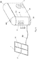
- the photovoltaic panel is a flexible foldable and/or rolling and/or swivelling photovoltaic panel.
- the liquid storage tank has a substantially cylindrical or a substantially prismatic shape, and comprises a base.
- the heat pump comprises a condenser, said condenser comprising a refrigerant conduit being arranged to be bent so that the area of the bent refrigerant conduit is substantially equal or inferior to the area of said base.
- the refrigerant conduit being arranged to be bent so as to form a spiral.
- the system comprises a container for receiving said liquid storage tank.
- the condenser is in contact with said base and/or with said container.
- the system comprises a hermetic cap for hermetically closing said liquid storage tank.
- the system is arranged to heat the liquid of the liquid storage tank.
- the system is arranged to pasteurize the liquid of the liquid storage tank.
- said liquid is water.
- the heat pump is arranged to heat said water to a temperature of at least 70 °C.
- the heat pump is arranged to hold the temperature of at least 70 °C for a time less than 5 minutes.
- control unit (2) comprises an energy storage unit, for example a super-capacity, arranged so as to store at least the energy necessary for heating said water to a temperature of at least 70 °C.
- energy storage unit for example a super-capacity
- the system is arranged to cool the liquid of the liquid storage tank.
- the liquid storage tank is a first liquid storage tank, the system comprising a second liquid storage tank, the system being arranged to transfer the heat generated by cooling the liquid of the first liquid storage tank to the second liquid storage tank so as to pre-heating the liquid of said second liquid storage tank.
- control unit comprises an inverter generating an AC current signal, the heat pump being arranged to work with said AC current signal.
- the off-grid renewable energy source is arranged to power the control unit.
- control unit is arranged to perform at least one of the following tasks:
- the off-grid renewable energy source is portable, and/or the liquid storage tank is portable.
- the liquid storage tank is arranged to contain a volume of liquid inferior to 50 I, for example inferior to 30 I.
- the present invention concerns also a method for modifying the temperature of a liquid, comprising
- Fig. 1 shows a schematic view of one embodiment of a system 100 for modifying the temperature of a liquid according to the invention, in particular to achieve the pasteurization of the liquid.
- the liquid is contained in a liquid storage tank 4.
- the illustrated system comprises:
- off-grid energy source means an energy source not connected to a main or national electrical grid (i.e. "off-grid”).
- an off-grid energy source is electrically autonomous, as it does not depend on a connection to an external grid.
- renewable energy source means an energy source exploiting renewable resources in nature such as (but not limited to) sunlight, wind, rain, tides, waves, geothermal heat, etc.
- off-grid renewable energy source means then a renewable energy source not connected to a main or national electrical grid.
- the system according to the invention is completely powered by an off-grid renewable energy source and the system can be portable.
- the off-grid renewable energy source 1 comprises a photovoltaic panel.
- this embodiment is not limitative, as other off-grid renewable energy sources 1 could be used instead, for example and in a non-limitative way a wind turbine.
- the system illustrated in Fig. 1 comprises also a control device or control unit 2, arranged to connect the off-grid renewable energy source 1 with the heat pump 3.
- the heat pump 3 provides heat energy from a source of heat (e.g. the ambient air) to the liquid storage tank 4, by exploiting the physical properties of the refrigerant, i.e. a volatile evaporating and condensing fluid, circulating in the pipes or tubes or conduits 35.
- An electric resistant heating element (not illustrated) can be added and e.g. immersed in the liquid of the tank 4, in order to support the heating up process. This electric resistant heating element is powered by the energy from the off-grid renewable energy source 1.
- the heat pump 3 comprises an evaporator 31, a compressor 32, a condenser 33 and an expansion valve 34.
- the heat pump 3 is a heat pump using a known refrigerant, e.g. and in a non-limiting way a R134a heat pump or a R600a (isobutane) heat pump or R123 heat pump.
- the system according to the invention can be manufactured at low cost, as all components of the heat pump, except the condenser, can be available in the market as components for high-volumes industries, e.g. automotive, air conditioning etc. Therefore, those components are available at low cost.
- the off-grid renewable energy source 1 is arranged to generate an electric power signal having a power equal or inferior to 500 W.
- the power signal has a power equal or inferior to 300 W, e.g. 150 W or less.
- This power signal activates the control unit 2 and provides the power necessary for the working of compressor 32 of the heat pump 3. If the evaporator 31 comprises also a fan, so as to raise the efficiency of the heat pump 3, the electric power signal generates the power necessary for the working of the fan too.
- the heat pump 3 is configured to work with this "small" electric power signal, i.e. with a power signal having a power equal or inferior to 500 W. If an electric resistant heating element is added and immersed in the liquid of the tank in order to support the critical stages of the heating up process and the maintaining stage of the temperature of the liquid, the electric resistant heating element is operated by the control unit 2 with a power signal having a power equal or inferior to 500 W.
- the applicant was confronted to the problem to raise the temperature of the liquid, e.g. the water, in the tank 4 so as to pasteurize it in an efficient way and by using only the energy from off-grid renewable energy source 1.
- he had to raise the efficiency of the heat-pump, by imaging a condenser 33 having a particular position and/or shape, as will be discussed.
- the liquid contained in the liquid storage tank 4 is water
- the system according to the invention is arranged to pasteurize the water, i.e. to raise its temperature to a temperature T 2 of at least 70 °C, by exploiting the temperature of the ambient air, which is around 20-30 °C.
- the temperature of the ambient air can be also in the range of 15-25°C or above, without compromising the working of the system.
- the temperature T 2 is maintained for a predetermined period, e.g. for few minutes. In one embodiment, the temperature T 2 is maintained for less than 5 minutes, e.g. for 2 minutes.
- the liquid storage tank 4 can comprise one or more temperature sensors (not illustrated) for sensing the temperature of the liquid and it can send this information to the control unit 2, for example to stop the process when the pasteurization is achieved. Other temperature sensors sensing the temperature outside the system, e.g. the air temperature, can communicate as well with the control unit 2.
- the heat pump 3 of the system according to the invention is arranged to
- the liquid storage tank 4 has a substantially cylindrical or substantially prismatic shape.
- the liquid storage tank 4 has a cylindrical shape and comprises a base 44, visible e.g. in Fig. 2 , having a round shape.
- the liquid storage tank 4 comprises also an opening 46, indicated in Fig. 2 , through which the liquid can be directly poured in the tank 4.
- the liquid storage tank 4 is then "inlet free", i.e. it does not require any pressure for inserting the liquid in the tank 4.
- the liquid storage tank 4 can comprise one or more outlets, e.g. taps, for allowing the exit of the liquid from the tank.
- the liquid storage tank 4 comprises a hermetic cap 40 for hermetically closing the opening 46 of the liquid storage tank 4.
- the liquid in tank 4 e.g. water
- the liquid in tank 4 once pasteurised avoids to be recontaminated or infected by external agents.
- the dimensions of the liquid storage tank 4 are arranged so that the liquid storage tank 4 is portable, i.e. can be moved and/or transported by a person.
- the liquid storage tank 4 has a volume inferior to 50 I, e.g. 30 I or less, its height is less than 1 m, e.g. 50 cm, and the diameter of its base 44 is less than 50 cm, e.g. 40 cm.
- the cap 40 of the liquid storage tank 4 comprises at least a handle 48, illustrated in Fig. 5 , for facilitating the transport of the tank 4.
- the off-grid renewable energy source 1 is portable as well.
- it can be a photovoltaic panel having a main surface of few m 2 , for example 1 m 2 .
- the off-grid renewable energy source 1 is used outdoor and the liquid storage tank 4 indoor, e.g. in a house.
- the off-grid renewable energy source 1 can be connected to the liquid storage tank 4 by one or more power cable 50, visible e.g. in Fig. 5 .
- the length of these cables 50 is inferior to 25 m, e.g. 20 m or 15 m.
- the off-grid renewable energy source 1 can be easily moved indoor by one person, when the natural energy resource (e.g. the sun) is not available (e.g. at night).
- the direct contact between the liquid storage tank 4 and the condenser 33 allows to efficiently exploit the heat generate by the condenser 33.
- the off-grid renewable energy source 1 is a flexible foldable and/or rolling and/or swivelling photovoltaic panel which can be supported and/or embedded and/or inserted in and/or installed upon the container 36 containing the heat pump 3 and visible e.g. in Fig. 5 and/or in its cap 38, which will be discussed later.
- the off-grid renewable energy source 1 can be oriented, i.e. can change its orientation in an automatic and/or manual way, so as to use in a more efficient way the natural energy resources (e.g. the sun).
- the condenser 33 of the heat pump 3 of the system 100 comprises a refrigerant conduit or pipe of a heat conductive material, e.g. copper or aluminium.
- the refrigerant pipe can be arranged to be bent so that the area of the bent refrigerant conduit is substantially equal or inferior to the area of the base 44 of the liquid storage tank 4.
- the refrigerant conduit is arranged to be bent so as to form a spiral.
- other shapes e.g. sinus-shape, etc., can be imagined.
- the condenser 33 can be put near to or directly in contact with the base of the tank 4, so as to heat the temperature of the liquid contained in the tank, as illustrated in Figs. 3 and 5 .
- the tank is made of heat conductive material, e.g. aluminium.
- a container 42 receives the condenser 33 to be near to or put in contact with the base of the tank 4.
- the container 42 can be made of thermal insulation material and cover the whole outer surface of the tank and the condenser that touches the outer surface of the tank.
- This kind of condenser 33 does not enter in contact with the liquid, so it is not necessary to protect it against e.g. the limestone.
- the refrigerant conduit or pipe of the condenser 33 forms a helical entering into contact with the vertical inner or outer surfaces of the tank.
- this helical can be combined with the spiral on the bottom of the tank.
- the shape of the condenser 33 is a spiral for the first part of the condenser in contact with the bottom internal or external surface of the tank 4, and the shape of the condenser is a helical spiral for the second part of the condenser in contact with the vertical internal or external surface of the tank.
- Fig. 7 shows a perspective view of an embodiment of the condenser 33 according to the invention, placed in an insulation plate 43, i.e. a plate made by a thermal insulation material, that limits heat dispersion towards any other direction than the water tank outer surface.
- this plate 43 has a shape defining a receptacle in which the condenser 33 can be placed.
- the receptacle or cavity arranged to receive the condenser 33 is defined by an edge having a thickness at least equal or higher that the thickness of the condenser 33: in such a way, this edge limits heat dispersion from the condenser 33 towards the other directions different from direction of the liquid tank 4, that will be placed on the condenser 33. Therefore, the heat from the condenser 33 is directed only to the liquid tank 4.
- This plate 43 allows then to improve the efficiency of the overall system.
- the condenser 33 comprises some maintaining means for maintaining the desired shape of the condenser 33 on the tank, e.g. the shape of spiral.
- Non-limitative example of such maintaining means comprise bars, in particular clamps made by the same material of the condenser, or welding or soldering connections between the spires of the condenser 33.
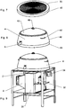
- the container 42 made e.g. by a thermal insulation material, is placed on the surface defined by the condenser 33 and the plate 43, and a tank 4 is inserted in the container 42.
- the illustrated container 42 has one or more handles 48, for facilitating its handling and transporting.
- the container 42 is portable.
- the container 42 is mono-bloc.
- the cap 40 is used for closing the tank 4.
- the cap can be made by a thermal insulation material too and can comprise a handle 48 as well.
- a tap 9 allows the exit of the liquid from the tank 4.
- the condenser and the tank are placed on the container 36, which in this example is a chassis box (here partially illustrated for clarity purposes, for a complete view see Fig. 10 ).
- This chassis box 36 comprises other components of the heat pump, i.e. the evaporator 31, the compressor 32 and the expansion valve 34.
- the same container 36 contains also the control unit 2, a fan and an air manifold to the fan 8.
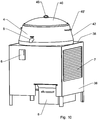
- Fig. 10 shows a perspective view of the complete system which was just partially illustrated in Fig. 9 .
- the chassis box 36 includes a lower container to gather the air condensate 5. It includes vertical walls hiding or protecting the inner components of the heat pump and of the control unit. It comprises one or more openings 7, allowing the access of the air to the evaporator 31 within the chassis box 36. It comprises also a human-machine interface 6.
- the chassis box 36 can be placed indoor for providing hot water ready for consumption (e.g. for cooking, infusion, etc.) and/or cold water obtained through the refrigeration cycle.
- the chassis box 36 including the heat pump system and the container 42 of the condenser and the liquid storage tank, can have a total size of less than 1 m x 50 cm x 50 cm, e.g. 70 cm x 40 cm x 40 cm or less. It is portable, i.e. can be moved or transported by a person. It has some legs (four in the example), for improving the ergonomics of the system.
- the liquid storage tank 4 is a pot, used e.g. for cooking. Once the liquid has modified its temperature in particular to achieve pasteurization of the liquid, the cap 48 will guarantee the absence of recontamination of the water. In the embodiment wherein the condenser is external to the pot, as illustrated in Figs 7 to 10 , the pot can be therefore easily removed from the rest of the heat pump 3, in particular from the chassis box 36 containing the heat pump 3.
- the part of the condenser directly in contact with the pot is planar or made planar, e.g. through soldering of condenser pipes, tinplating or welding a planar metal plate on the condenser.
- the tap 9 can be protected from external contact through mechanical design and haptic means to require the system to heat the tap 9 just before the liquid pass through it, so as to sterilize it.
- the liquid storage tank 4 of Fig. 2 and 5 is made by a conductive material, e.g. aluminium, so as to transmit the heat from the condenser 33 to the liquid.
- the container 42 of Fig. 5 is made by a material that is not necessarily a conductive material, e.g. it is made of plastic or in general of a thermal insulation material.
- the system according to the invention comprises an opening 7, allowing the entering of the air in the system so that its temperature can be exploited by the heat pump 3.
- the heat pump 3 is contained in a chassis box 36.
- the chassis box 36 and container 42 constitute a single and mono-bloc container, arranged to receive both the liquid storage tank 4 and the heat pump 3. In another embodiment, they are two separated but linked containers.
- the chassis box 36 comprises a cap 38.
- the centre of the spiral is the point of the condenser 33 having the highest temperature T 1 , e.g. 80-90 °C.
- T 1 e.g. 80-90 °C.
- the described condenser 33 allows then to raise the efficiency of the heat pump 3 of the system 100.
- Fig. 6 shows a schematic view of another embodiment of a system according to the invention, comprising the off-grid renewable energy source 1, the control unit 2 and the heat pump 3.
- the control unit 2 comprises a charge controller 21, connected to an inverter 22, which allows to generate an AC electric signal.
- the heat pump 3 is arranged to work with this AC electric signal.
- the control unit 2 comprises a micro-controller 23, connected to the inverter 22, a human-machine interface 6 (an example of this interface being illustrated in Fig. 5 ), an electric storage unit 24 and the heat pump 3.
- the micro-controller 23 includes the electric drivers to operate the different electric engines that are present in the heat pump 3, e.g. for the compressor and the fan.
- control unit 2 is arranged to perform at least one of the following tasks:
- the system according to the invention comprises the energy storage unit 24, for example a supercapacitor or a battery, which is arranged so as to store at least the energy necessary for completing a pasteurization cycle through the heat pump 3.
- the energy storage unit 24 can be used for completing the cycle without interruptions.
- control unit 2 comprises a printed circuit board (PCB), which can comprise the inverter 22, e.g. an integrated inverter.
- PCB printed circuit board
- the PCB comprises the human-machine interface 6.
- control unit 2 is connected to an external inverter and/or to an external human-machine interface 6.
- control unit 2 comprises a connection to an external battery, e.g. a 12 V or a 24 V battery.
- This connection can be placed in the human-machine interface 6.
- This battery can be used in addition and/or instead of the energy storage unit 24 mentioned here above, so as to have a supplementary storage of energy to be used. An excess of storage energy can be used e.g. for charging mobile phones or low power lamps.
- the human-machine interface 6 comprises a connection for charging portable devices as e.g. a smartphone.
- the energy from the photovoltaic panel (1) and/or the energy stored in the supercapacitor or battery 24 is used for charging the portable devices, e.g. via a USB port.
- control unit 2 comprises a connection to an electric grid.
- the human-machine interface 6 comprises at least one haptic means 61, i.e. a means allowing to perform an action when it enters into contact with a user (e.g. a finger of the user) or an object as e.g. a stylus.
- haptic means comprise buttons, touch-screens, etc.
- the haptic means 61 is a switch allowing to switch on and/or off the system 100.
- the human-machine interface 6 comprises one or more visual or audio elements 62, 63, e.g. LED of different colours, indicating that the system is ON and/or that the pasteurization cycle is completed and/or that the pasteurization cycle is ready to start and/or that there is an error or a problem to any component and/or the battery level.
- the system according to the invention comprises security means, allowing e.g. to stop the system if the temperatures of the liquid T 1 and/or T 2 are higher than a threshold, e.g. higher than 80 °C.
- the heat pump 3 of the system according to the invention can be used also for cooling the liquid of the liquid storage tank 4.
- the system comprises a second liquid storage tank (not illustrated), the system being arranged to transfer the heat generated by cooling the liquid of the first liquid storage tank (for example from 70 °C to 15 °C) to the second liquid storage tank so as to pre-heating the liquid of the second liquid storage tank (for example to a temperature of 40 °C).
- the temperature of the liquid of the second liquid storage tank can then be raised to 70 °C in a more efficient and rapid way.
- the present invention concerns also a method for pasteurizing a liquid contained in a liquid storage tank 4, the method comprising
- the liquid storage tank 4 is removed from the first container 36 after the pasteurization.
Landscapes
- Chemical & Material Sciences (AREA)
- Life Sciences & Earth Sciences (AREA)
- Hydrology & Water Resources (AREA)
- Engineering & Computer Science (AREA)
- Environmental & Geological Engineering (AREA)
- Water Supply & Treatment (AREA)
- Organic Chemistry (AREA)
- Chemical Kinetics & Catalysis (AREA)
- Heat-Pump Type And Storage Water Heaters (AREA)
Claims (15)
- Un système (100) pour pasteuriser un liquide dans un réservoir de stockage de liquide (4), le système comprenant :- une source d'énergie renouvelable hors-réseau (1) agencée pour générer un signal de puissance électrique ayant une puissance égale ou inférieure à 500 W, la source d'énergie renouvelable hors-réseau (1) étant portable,- le réservoir de stockage de liquide (4) étant portable, étant arrangé pour contenir un volume de liquide inférieur à 50 l, par exemple inférieur à 30 l, et comprenant une poignée (48) pour faciliter le transport du réservoir de stockage de liquide (4), par exemple après la pasteurisation dudit liquide,- un premier récipient (36) comprenant une pompe à chaleur (3), ladite pompe à chaleur (3) étant agencée pour être complètement alimentée par ladite source d'énergie renouvelable hors-réseau (1),- la pompe à chaleur (3) comprenant un condenseur (33) proche ou directement en contact avec un fond (44) du réservoir (4), le condenseur (33) étant agencé pour chauffer le liquide contenu dans le réservoir (4) pour pasteuriser ledit liquide.
- Système selon la revendication 1, une source d'énergie renouvelable hors-réseau (1) comprenant un panneau photovoltaïque, ledit panneau photovoltaïque étant un panneau photovoltaïque flexible pliable et/ou roulant et/ou pivotant, ledit panneau photovoltaïque une fois plié étant arrangé pour être relié ou emballé au réservoir de stockage de liquide (4), par exemple lié et/ou inséré dans sa paroi latérale et/ou installé sur le premier récipient (36) de manière à le transporter avec le réservoir de stockage de liquide (4).
- Système selon l'une des revendications 1 à 2, ledit réservoir de stockage de liquide (4) étant un pot conçu pour être retiré du premier récipient (36).
- Système selon l'une des revendications 1 à 3, ledit premier conteneur (36) étant portable et/ou ladite pompe à chaleur (3) étant portable.
- Système selon l'une des revendications 1 à 4, ledit condenseur (33) comprenant un conduit réfrigérant étant agencé pour être plié de sorte que la surface du conduit de réfrigérant plié soit sensiblement égale ou inférieure à la surface de ladite base (44).
- Système selon la revendication précédente, le conduit réfrigérant étant conçu pour être plié de manière à former une spirale.
- Système selon l'une des revendications 5 à 6, le conduit réfrigérant étant agencé pour être plié de manière à former une hélice entrant en contact avec une des surfaces verticales intérieure ou extérieure du réservoir (4).
- Système selon l'une des revendications 1 à 7, ledit condenseur (33) étant en contact avec une surface interne ou externe du réservoir (4), ou étant incorporé dans la base (44) du réservoir, ou immergé sur le liquide du réservoir.
- Système selon l'une des revendications 1 à 8, comprenant un deuxième récipient (42) comprenant ledit réservoir de stockage de liquide (4).
- Système selon l'une des revendications précédentes, comprenant une unité de commande (2) étant agencée pour connecter la source d'énergie renouvelable hors-réseau (1) à la pompe à chaleur (3) en transférant de la puissance électrique à partir de ladite source d'énergie renouvelable hors-réseau. (1) à ladite pompe à chaleur (3).
- Système selon la revendication précédente, ladite unité de commande (2) comprenant une unité de stockage d'énergie (24), par exemple un super-condensateur, agencée de manière à stocker au moins l'énergie nécessaire, par exemple pour chauffer ladite eau à une température d'au moins 70 ° C.
- Système selon l'une des revendications 10 à 11, ladite unité de commande (2) comprenant une connexion pour charger des dispositifs portables, comme par exemple un smartphone en utilisant l'énergie de la source d'énergie renouvelable hors-réseau.
- Système selon l'une des revendications précédentes, le système étant agencé pour refroidir le liquide du réservoir de stockage de liquide (4), ledit réservoir de stockage de liquide (4) étant un premier réservoir de stockage de liquide, le système comprenant un second réservoir de stockage de liquide, le système étant agencé pour transférer la chaleur générée par le refroidissement du liquide du premier réservoir de stockage de liquide (4) vers le deuxième réservoir de stockage de liquide de manière à préchauffer le liquide dudit deuxième réservoir de stockage de liquide.
- Système selon l'une des revendications 10 à 13, l'unité de contrôle (2) étant agencée pour effectuer au moins l'une des tâches suivantes :- recevoir le signal de puissance de la source d'énergie renouvelable hors-réseau (1) et en transmettre au moins une partie au circuit de pompe à chaleur (3)- recevoir le signal de puissance de la source d'énergie renouvelable hors-réseau (1) et charger l'unité de stockage d'énergie (24)- gérer l'énergie stockée dans l'unité de stockage d'énergie (24)- gérer une interface homme-machine (6)- gérer les signaux des capteurs de température placés sur le réservoir de stockage de liquide (4) et/ou sur l'évaporateur (31) et/ou sur la source d'énergie renouvelable hors-réseau (1)- mesurer le temps pendant lequel la température du liquide dans le réservoir de stockage de liquide (4) reste au-dessus du point de pasteurisation (T2)- arrêter le fonctionnement du système lorsque le cycle de pasteurisation est terminé- arrêter le fonctionnement du système en cas de surchauffe et/ou d'erreur.
- Procédé de pasteurisation d'un liquide contenu dans un réservoir de stockage de liquide (4), le procédé comprenant- générer un signal de puissance électrique ayant une puissance égale ou inférieure à 500 W en utilisant une source d'énergie renouvelable hors-réseau (1), la source d'énergie renouvelable hors-réseau (1) étant portable,- alimenter complètement une pompe à chaleur (3) en utilisant ledit signal de puissance, la pompe à chaleur (3) se trouvant dans un premier récipient (36) et comprenant un condenseur (33) à proximité de ou directement en contact avec une base (44) du réservoir de liquide (4), le condenseur (33) étant agencé pour chauffer le liquide contenu dans le réservoir (4) afin de pasteuriser ledit liquide,- transporter le réservoir de liquide (4) en utilisant une poignée (48) du réservoir de liquide (4).
Applications Claiming Priority (2)
| Application Number | Priority Date | Filing Date | Title |
|---|---|---|---|
| CH17392014 | 2014-11-10 | ||
| PCT/IB2015/058659 WO2016075614A1 (fr) | 2014-11-10 | 2015-11-10 | Système et procédé de pasteurisation d'un liquide |
Publications (2)
| Publication Number | Publication Date |
|---|---|
| EP3218310A1 EP3218310A1 (fr) | 2017-09-20 |
| EP3218310B1 true EP3218310B1 (fr) | 2019-04-10 |
Family
ID=54697622
Family Applications (1)
| Application Number | Title | Priority Date | Filing Date |
|---|---|---|---|
| EP15798572.2A Active EP3218310B1 (fr) | 2014-11-10 | 2015-11-10 | Système et procédé de pasteurisation d'un liquide |
Country Status (2)
| Country | Link |
|---|---|
| EP (1) | EP3218310B1 (fr) |
| WO (1) | WO2016075614A1 (fr) |
Family Cites Families (6)
| Publication number | Priority date | Publication date | Assignee | Title |
|---|---|---|---|---|
| US4316774A (en) * | 1979-07-05 | 1982-02-23 | United Technologies Corporation | Thermoelectric integrated membrane evaporation system |
| DE102004033409A1 (de) * | 2004-06-28 | 2006-01-12 | Retter, Timm, Dr. | Wasserentsalzungsanlage unter Verwendung eines Sonnenkollektors, eines Peltierelementes oder einer mechanischen Wärmepumpe mit teilweiser Rückgewinnung der Energie |
| GB2447411A (en) * | 2007-03-14 | 2008-09-17 | Stuart John Burrell | Mobile Condensing Unit |
| WO2009021090A1 (fr) | 2007-08-07 | 2009-02-12 | Ohio University | Pompe thermique à base de dioxyde de carbone pour purifier l'eau |
| CH703162A1 (fr) | 2010-05-17 | 2011-11-30 | Cosseco Sa | Système de récupération d'énergie rénouvelable. |
| WO2013107469A1 (fr) * | 2012-01-19 | 2013-07-25 | Anes Sbuelz | Station de dessalement utilisant une pompe à chaleur et de l'énergie photovoltaïque |
-
2015
- 2015-11-10 WO PCT/IB2015/058659 patent/WO2016075614A1/fr not_active Ceased
- 2015-11-10 EP EP15798572.2A patent/EP3218310B1/fr active Active
Non-Patent Citations (1)
| Title |
|---|
| None * |
Also Published As
| Publication number | Publication date |
|---|---|
| EP3218310A1 (fr) | 2017-09-20 |
| WO2016075614A1 (fr) | 2016-05-19 |
Similar Documents
| Publication | Publication Date | Title |
|---|---|---|
| US20170108233A1 (en) | Portable Solar HVAC System with All-In-One Appliances | |
| CN102563960B (zh) | 太阳能冷热电三联供系统 | |
| BRPI0715993A2 (pt) | sistema de armazenamento de energia tÉrmica ativa | |
| Cho | Comparative study on the performance and exergy efficiency of a solar hybrid heat pump using R22 and R744 | |
| CN204026993U (zh) | 一种多功能热泵开水装置 | |
| EP3218310B1 (fr) | Système et procédé de pasteurisation d'un liquide | |
| GB2578409A (en) | Hot water tank | |
| CA2914194A1 (fr) | Systeme integre a energie renouvelable | |
| CN208625360U (zh) | 光伏空调和饮水机的集成装置 | |
| CN203572134U (zh) | 节能型组合家电 | |
| CN202613784U (zh) | 太阳能加热系统 | |
| CN104019545A (zh) | 一种多功能热泵开水装置 | |
| EP2956722A1 (fr) | Appareil chauffant l'eau | |
| CN113310105A (zh) | 一种制冷-制热多温区间综合供水系统及方法 | |
| CN104456939A (zh) | 一种太阳能热水器 | |
| CN101101159A (zh) | 冷/暖气装置 | |
| CN102901161A (zh) | 一种太阳能地温空调 | |
| CN204345843U (zh) | 一种光伏地源热泵一体化的供暖空调系统 | |
| CN205048621U (zh) | 电子环保冷热风机 | |
| WO2015140683A1 (fr) | Chauffe-eau à accumulation | |
| CN201348306Y (zh) | 一种有源散热器及应用该有源散热器的采暖装置 | |
| CN204787424U (zh) | 一种高温热泵一体机 | |
| CN203111856U (zh) | 一种降温储水装置 | |
| CN104848580B (zh) | 太阳能联合供暖制冷系统及其使用方法 | |
| CN101469883A (zh) | 楼房用全天候太阳能热水器 |
Legal Events
| Date | Code | Title | Description |
|---|---|---|---|
| STAA | Information on the status of an ep patent application or granted ep patent |
Free format text: STATUS: THE INTERNATIONAL PUBLICATION HAS BEEN MADE |
|
| PUAI | Public reference made under article 153(3) epc to a published international application that has entered the european phase |
Free format text: ORIGINAL CODE: 0009012 |
|
| STAA | Information on the status of an ep patent application or granted ep patent |
Free format text: STATUS: REQUEST FOR EXAMINATION WAS MADE |
|
| 17P | Request for examination filed |
Effective date: 20170509 |
|
| AK | Designated contracting states |
Kind code of ref document: A1 Designated state(s): AL AT BE BG CH CY CZ DE DK EE ES FI FR GB GR HR HU IE IS IT LI LT LU LV MC MK MT NL NO PL PT RO RS SE SI SK SM TR |
|
| AX | Request for extension of the european patent |
Extension state: BA ME |
|
| DAV | Request for validation of the european patent (deleted) | ||
| DAX | Request for extension of the european patent (deleted) | ||
| GRAP | Despatch of communication of intention to grant a patent |
Free format text: ORIGINAL CODE: EPIDOSNIGR1 |
|
| STAA | Information on the status of an ep patent application or granted ep patent |
Free format text: STATUS: GRANT OF PATENT IS INTENDED |
|
| INTG | Intention to grant announced |
Effective date: 20181025 |
|
| GRAJ | Information related to disapproval of communication of intention to grant by the applicant or resumption of examination proceedings by the epo deleted |
Free format text: ORIGINAL CODE: EPIDOSDIGR1 |
|
| STAA | Information on the status of an ep patent application or granted ep patent |
Free format text: STATUS: REQUEST FOR EXAMINATION WAS MADE |
|
| GRAR | Information related to intention to grant a patent recorded |
Free format text: ORIGINAL CODE: EPIDOSNIGR71 |
|
| GRAS | Grant fee paid |
Free format text: ORIGINAL CODE: EPIDOSNIGR3 |
|
| STAA | Information on the status of an ep patent application or granted ep patent |
Free format text: STATUS: GRANT OF PATENT IS INTENDED |
|
| GRAA | (expected) grant |
Free format text: ORIGINAL CODE: 0009210 |
|
| STAA | Information on the status of an ep patent application or granted ep patent |
Free format text: STATUS: THE PATENT HAS BEEN GRANTED |
|
| INTC | Intention to grant announced (deleted) | ||
| AK | Designated contracting states |
Kind code of ref document: B1 Designated state(s): AL AT BE BG CH CY CZ DE DK EE ES FI FR GB GR HR HU IE IS IT LI LT LU LV MC MK MT NL NO PL PT RO RS SE SI SK SM TR |
|
| INTG | Intention to grant announced |
Effective date: 20190306 |
|
| REG | Reference to a national code |
Ref country code: GB Ref legal event code: FG4D |
|
| REG | Reference to a national code |
Ref country code: CH Ref legal event code: EP Ref country code: AT Ref legal event code: REF Ref document number: 1118409 Country of ref document: AT Kind code of ref document: T Effective date: 20190415 |
|
| REG | Reference to a national code |
Ref country code: IE Ref legal event code: FG4D |
|
| REG | Reference to a national code |
Ref country code: DE Ref legal event code: R096 Ref document number: 602015028170 Country of ref document: DE |
|
| REG | Reference to a national code |
Ref country code: CH Ref legal event code: NV Representative=s name: P&TS SA, CH |
|
| REG | Reference to a national code |
Ref country code: NL Ref legal event code: MP Effective date: 20190410 |
|
| REG | Reference to a national code |
Ref country code: LT Ref legal event code: MG4D |
|
| REG | Reference to a national code |
Ref country code: AT Ref legal event code: MK05 Ref document number: 1118409 Country of ref document: AT Kind code of ref document: T Effective date: 20190410 |
|
| PG25 | Lapsed in a contracting state [announced via postgrant information from national office to epo] |
Ref country code: NL Free format text: LAPSE BECAUSE OF FAILURE TO SUBMIT A TRANSLATION OF THE DESCRIPTION OR TO PAY THE FEE WITHIN THE PRESCRIBED TIME-LIMIT Effective date: 20190410 |
|
| PG25 | Lapsed in a contracting state [announced via postgrant information from national office to epo] |
Ref country code: ES Free format text: LAPSE BECAUSE OF FAILURE TO SUBMIT A TRANSLATION OF THE DESCRIPTION OR TO PAY THE FEE WITHIN THE PRESCRIBED TIME-LIMIT Effective date: 20190410 Ref country code: AL Free format text: LAPSE BECAUSE OF FAILURE TO SUBMIT A TRANSLATION OF THE DESCRIPTION OR TO PAY THE FEE WITHIN THE PRESCRIBED TIME-LIMIT Effective date: 20190410 Ref country code: SE Free format text: LAPSE BECAUSE OF FAILURE TO SUBMIT A TRANSLATION OF THE DESCRIPTION OR TO PAY THE FEE WITHIN THE PRESCRIBED TIME-LIMIT Effective date: 20190410 Ref country code: HR Free format text: LAPSE BECAUSE OF FAILURE TO SUBMIT A TRANSLATION OF THE DESCRIPTION OR TO PAY THE FEE WITHIN THE PRESCRIBED TIME-LIMIT Effective date: 20190410 Ref country code: PT Free format text: LAPSE BECAUSE OF FAILURE TO SUBMIT A TRANSLATION OF THE DESCRIPTION OR TO PAY THE FEE WITHIN THE PRESCRIBED TIME-LIMIT Effective date: 20190910 Ref country code: NO Free format text: LAPSE BECAUSE OF FAILURE TO SUBMIT A TRANSLATION OF THE DESCRIPTION OR TO PAY THE FEE WITHIN THE PRESCRIBED TIME-LIMIT Effective date: 20190710 Ref country code: LT Free format text: LAPSE BECAUSE OF FAILURE TO SUBMIT A TRANSLATION OF THE DESCRIPTION OR TO PAY THE FEE WITHIN THE PRESCRIBED TIME-LIMIT Effective date: 20190410 Ref country code: FI Free format text: LAPSE BECAUSE OF FAILURE TO SUBMIT A TRANSLATION OF THE DESCRIPTION OR TO PAY THE FEE WITHIN THE PRESCRIBED TIME-LIMIT Effective date: 20190410 |
|
| PG25 | Lapsed in a contracting state [announced via postgrant information from national office to epo] |
Ref country code: LV Free format text: LAPSE BECAUSE OF FAILURE TO SUBMIT A TRANSLATION OF THE DESCRIPTION OR TO PAY THE FEE WITHIN THE PRESCRIBED TIME-LIMIT Effective date: 20190410 Ref country code: RS Free format text: LAPSE BECAUSE OF FAILURE TO SUBMIT A TRANSLATION OF THE DESCRIPTION OR TO PAY THE FEE WITHIN THE PRESCRIBED TIME-LIMIT Effective date: 20190410 Ref country code: PL Free format text: LAPSE BECAUSE OF FAILURE TO SUBMIT A TRANSLATION OF THE DESCRIPTION OR TO PAY THE FEE WITHIN THE PRESCRIBED TIME-LIMIT Effective date: 20190410 Ref country code: GR Free format text: LAPSE BECAUSE OF FAILURE TO SUBMIT A TRANSLATION OF THE DESCRIPTION OR TO PAY THE FEE WITHIN THE PRESCRIBED TIME-LIMIT Effective date: 20190711 Ref country code: BG Free format text: LAPSE BECAUSE OF FAILURE TO SUBMIT A TRANSLATION OF THE DESCRIPTION OR TO PAY THE FEE WITHIN THE PRESCRIBED TIME-LIMIT Effective date: 20190710 |
|
| PG25 | Lapsed in a contracting state [announced via postgrant information from national office to epo] |
Ref country code: IS Free format text: LAPSE BECAUSE OF FAILURE TO SUBMIT A TRANSLATION OF THE DESCRIPTION OR TO PAY THE FEE WITHIN THE PRESCRIBED TIME-LIMIT Effective date: 20190810 Ref country code: AT Free format text: LAPSE BECAUSE OF FAILURE TO SUBMIT A TRANSLATION OF THE DESCRIPTION OR TO PAY THE FEE WITHIN THE PRESCRIBED TIME-LIMIT Effective date: 20190410 |
|
| REG | Reference to a national code |
Ref country code: DE Ref legal event code: R097 Ref document number: 602015028170 Country of ref document: DE |
|
| PG25 | Lapsed in a contracting state [announced via postgrant information from national office to epo] |
Ref country code: DK Free format text: LAPSE BECAUSE OF FAILURE TO SUBMIT A TRANSLATION OF THE DESCRIPTION OR TO PAY THE FEE WITHIN THE PRESCRIBED TIME-LIMIT Effective date: 20190410 Ref country code: SK Free format text: LAPSE BECAUSE OF FAILURE TO SUBMIT A TRANSLATION OF THE DESCRIPTION OR TO PAY THE FEE WITHIN THE PRESCRIBED TIME-LIMIT Effective date: 20190410 Ref country code: CZ Free format text: LAPSE BECAUSE OF FAILURE TO SUBMIT A TRANSLATION OF THE DESCRIPTION OR TO PAY THE FEE WITHIN THE PRESCRIBED TIME-LIMIT Effective date: 20190410 Ref country code: EE Free format text: LAPSE BECAUSE OF FAILURE TO SUBMIT A TRANSLATION OF THE DESCRIPTION OR TO PAY THE FEE WITHIN THE PRESCRIBED TIME-LIMIT Effective date: 20190410 Ref country code: RO Free format text: LAPSE BECAUSE OF FAILURE TO SUBMIT A TRANSLATION OF THE DESCRIPTION OR TO PAY THE FEE WITHIN THE PRESCRIBED TIME-LIMIT Effective date: 20190410 |
|
| PLBE | No opposition filed within time limit |
Free format text: ORIGINAL CODE: 0009261 |
|
| STAA | Information on the status of an ep patent application or granted ep patent |
Free format text: STATUS: NO OPPOSITION FILED WITHIN TIME LIMIT |
|
| PG25 | Lapsed in a contracting state [announced via postgrant information from national office to epo] |
Ref country code: SM Free format text: LAPSE BECAUSE OF FAILURE TO SUBMIT A TRANSLATION OF THE DESCRIPTION OR TO PAY THE FEE WITHIN THE PRESCRIBED TIME-LIMIT Effective date: 20190410 |
|
| 26N | No opposition filed |
Effective date: 20200113 |
|
| PG25 | Lapsed in a contracting state [announced via postgrant information from national office to epo] |
Ref country code: TR Free format text: LAPSE BECAUSE OF FAILURE TO SUBMIT A TRANSLATION OF THE DESCRIPTION OR TO PAY THE FEE WITHIN THE PRESCRIBED TIME-LIMIT Effective date: 20190410 |
|
| PG25 | Lapsed in a contracting state [announced via postgrant information from national office to epo] |
Ref country code: SI Free format text: LAPSE BECAUSE OF FAILURE TO SUBMIT A TRANSLATION OF THE DESCRIPTION OR TO PAY THE FEE WITHIN THE PRESCRIBED TIME-LIMIT Effective date: 20190410 |
|
| PG25 | Lapsed in a contracting state [announced via postgrant information from national office to epo] |
Ref country code: MC Free format text: LAPSE BECAUSE OF FAILURE TO SUBMIT A TRANSLATION OF THE DESCRIPTION OR TO PAY THE FEE WITHIN THE PRESCRIBED TIME-LIMIT Effective date: 20190410 Ref country code: LU Free format text: LAPSE BECAUSE OF NON-PAYMENT OF DUE FEES Effective date: 20191110 |
|
| REG | Reference to a national code |
Ref country code: BE Ref legal event code: MM Effective date: 20191130 |
|
| PG25 | Lapsed in a contracting state [announced via postgrant information from national office to epo] |
Ref country code: IE Free format text: LAPSE BECAUSE OF NON-PAYMENT OF DUE FEES Effective date: 20191110 |
|
| PG25 | Lapsed in a contracting state [announced via postgrant information from national office to epo] |
Ref country code: BE Free format text: LAPSE BECAUSE OF NON-PAYMENT OF DUE FEES Effective date: 20191130 |
|
| PG25 | Lapsed in a contracting state [announced via postgrant information from national office to epo] |
Ref country code: CY Free format text: LAPSE BECAUSE OF FAILURE TO SUBMIT A TRANSLATION OF THE DESCRIPTION OR TO PAY THE FEE WITHIN THE PRESCRIBED TIME-LIMIT Effective date: 20190410 |
|
| PG25 | Lapsed in a contracting state [announced via postgrant information from national office to epo] |
Ref country code: MT Free format text: LAPSE BECAUSE OF FAILURE TO SUBMIT A TRANSLATION OF THE DESCRIPTION OR TO PAY THE FEE WITHIN THE PRESCRIBED TIME-LIMIT Effective date: 20190410 Ref country code: HU Free format text: LAPSE BECAUSE OF FAILURE TO SUBMIT A TRANSLATION OF THE DESCRIPTION OR TO PAY THE FEE WITHIN THE PRESCRIBED TIME-LIMIT; INVALID AB INITIO Effective date: 20151110 |
|
| PG25 | Lapsed in a contracting state [announced via postgrant information from national office to epo] |
Ref country code: MK Free format text: LAPSE BECAUSE OF FAILURE TO SUBMIT A TRANSLATION OF THE DESCRIPTION OR TO PAY THE FEE WITHIN THE PRESCRIBED TIME-LIMIT Effective date: 20190410 |
|
| REG | Reference to a national code |
Ref country code: CH Ref legal event code: U11 Free format text: ST27 STATUS EVENT CODE: U-0-0-U10-U11 (AS PROVIDED BY THE NATIONAL OFFICE) Effective date: 20251201 |
|
| PGFP | Annual fee paid to national office [announced via postgrant information from national office to epo] |
Ref country code: DE Payment date: 20251119 Year of fee payment: 11 |
|
| PGFP | Annual fee paid to national office [announced via postgrant information from national office to epo] |
Ref country code: GB Payment date: 20251121 Year of fee payment: 11 |
|
| PGFP | Annual fee paid to national office [announced via postgrant information from national office to epo] |
Ref country code: IT Payment date: 20251124 Year of fee payment: 11 |
|
| PGFP | Annual fee paid to national office [announced via postgrant information from national office to epo] |
Ref country code: FR Payment date: 20251126 Year of fee payment: 11 |
|
| PGFP | Annual fee paid to national office [announced via postgrant information from national office to epo] |
Ref country code: CH Payment date: 20251201 Year of fee payment: 11 |