EP3218580B1 - Anordnung für gebirgsanker und verfahren zur verwendung der anordnung sowie ein verstärkungssystem mit einer derartigen anordnung - Google Patents
Anordnung für gebirgsanker und verfahren zur verwendung der anordnung sowie ein verstärkungssystem mit einer derartigen anordnung Download PDFInfo
- Publication number
- EP3218580B1 EP3218580B1 EP15859518.1A EP15859518A EP3218580B1 EP 3218580 B1 EP3218580 B1 EP 3218580B1 EP 15859518 A EP15859518 A EP 15859518A EP 3218580 B1 EP3218580 B1 EP 3218580B1
- Authority
- EP
- European Patent Office
- Prior art keywords
- rock bolt
- arrangement
- bolt
- rock
- sensor
- Prior art date
- Legal status (The legal status is an assumption and is not a legal conclusion. Google has not performed a legal analysis and makes no representation as to the accuracy of the status listed.)
- Active
Links
Images


Classifications
-
- E—FIXED CONSTRUCTIONS
- E21—EARTH OR ROCK DRILLING; MINING
- E21D—SHAFTS; TUNNELS; GALLERIES; LARGE UNDERGROUND CHAMBERS
- E21D21/00—Anchoring-bolts for roof, floor in galleries or longwall working, or shaft-lining protection
- E21D21/02—Anchoring-bolts for roof, floor in galleries or longwall working, or shaft-lining protection having means for indicating tension
-
- E—FIXED CONSTRUCTIONS
- E21—EARTH OR ROCK DRILLING; MINING
- E21D—SHAFTS; TUNNELS; GALLERIES; LARGE UNDERGROUND CHAMBERS
- E21D20/00—Setting anchoring-bolts
- E21D20/02—Setting anchoring-bolts with provisions for grouting
-
- E—FIXED CONSTRUCTIONS
- E21—EARTH OR ROCK DRILLING; MINING
- E21D—SHAFTS; TUNNELS; GALLERIES; LARGE UNDERGROUND CHAMBERS
- E21D21/00—Anchoring-bolts for roof, floor in galleries or longwall working, or shaft-lining protection
- E21D21/0093—Accessories
-
- G—PHYSICS
- G01—MEASURING; TESTING
- G01L—MEASURING FORCE, STRESS, TORQUE, WORK, MECHANICAL POWER, MECHANICAL EFFICIENCY, OR FLUID PRESSURE
- G01L1/00—Measuring force or stress, in general
- G01L1/005—Measuring force or stress, in general by electrical means and not provided for in G01L1/06 - G01L1/22
-
- G—PHYSICS
- G01—MEASURING; TESTING
- G01L—MEASURING FORCE, STRESS, TORQUE, WORK, MECHANICAL POWER, MECHANICAL EFFICIENCY, OR FLUID PRESSURE
- G01L5/00—Apparatus for, or methods of, measuring force, work, mechanical power, or torque, specially adapted for specific purposes
-
- G—PHYSICS
- G01—MEASURING; TESTING
- G01L—MEASURING FORCE, STRESS, TORQUE, WORK, MECHANICAL POWER, MECHANICAL EFFICIENCY, OR FLUID PRESSURE
- G01L5/00—Apparatus for, or methods of, measuring force, work, mechanical power, or torque, specially adapted for specific purposes
- G01L5/0004—Force transducers adapted for mounting in a bore of the force receiving structure
-
- G—PHYSICS
- G08—SIGNALLING
- G08B—SIGNALLING SYSTEMS, e.g. PERSONAL CALLING SYSTEMS; ORDER TELEGRAPHS; ALARM SYSTEMS
- G08B5/00—Visible signalling systems, e.g. visible personal calling systems or remote indication of seats occupied
- G08B5/22—Visible signalling systems, e.g. visible personal calling systems or remote indication of seats occupied using electric transmission; using electromagnetic transmission
- G08B5/36—Visible signalling systems, e.g. visible personal calling systems or remote indication of seats occupied using electric transmission; using electromagnetic transmission using visible light sources
Definitions
- the invention concerns an arrangement for a rock bolt of the type that is specified in the introduction to claim 1, a method for the use of the arrangement, and a reinforcement system comprising the said arrangement.
- Bolting is the most common reinforcement of rock that is exposed to slow deformation or sudden fracture. Fundamental requirements for rock bolts are that they are to support a heavy load and to resist a large degree of elongation before the bolt breaks.
- a large number of rock bolts introduced into boreholes and anchored in them by means of embedding in grout form together a reinforcement system that stabilises and reinforces the rock structure during the building of tunnels, mining operations, tunnelling, etc.
- Bolts of this type normally have at their forward end an anchor arrangement such as a wedge for mechanical anchoring at the bottom of the borehole, and the bolt is provided at the end that is closest to the opening of the borehole with threads for the reception of a mounting fitting, normally in the form of a washer and nut, that is placed in contact with the area of rock material that surrounds the opening of the borehole.
- This type of rock reinforcement system achieves its principal load-bearing ability through the adhesion along the complete length of the rock bolt that the grout gives rise to.
- rock bolts that differ from the ribbed rock bolt through their being provided along a central part with a sheath or similar, whereby the embedding of the bolt takes place principally along two anchoring zones, partly along a forward section of the bolt at the bottom of the borehole and partly along a section of bolt closest to the opening of the borehole.
- a further type of rock bolt is a cable bolt or a wire bolt that consists of seven twisted steel threads. All of these types of bolt may be 3-10 m in length and are intended for embedding in grout.
- rock reinforcement systems that consist of embedded rock bolts are sometimes present, which are filled by that portion of the grout that is injected into the borehole, whereby the rock bolt that is subsequently introduced into it will be insufficient embedded in the borehole, which may have the consequence that the reinforcement system is deficient and achieves a reduced load-bearing ability.
- rock reinforcement systems that are used in fracture-rich rock are subject to heavy loads.
- the rock bolts may be placed under load locally at locations at which they cross large fractures between blocks, and thus subject to heavy loads that lead to the bolts becoming deformed, mainly through elongation and extension.
- WO2009/104687 describes a deformation detector for a rock bolt to detect the full length of the rock bolt buried in the ground, which detects relative displacement of a rigid cable connected to an elastic structure at the rock surface and to the deepest portion of the rock bolt buried in the ground.
- the deformation detector converts the relative displacement of the cable into color of light to display the deformation of the rock bolt.
- the load exceeds the ability of the rock bolt to absorb force, such that breaks of the rock bolt arise, whereby the reinforcement system is weakened.
- SE 533769 reveals a reinforcement means, a rock bolt, that has a tube with a passage for the introduction of a medium into the borehole.
- the wall of the tube is equipped with radially directed holes, openings.
- the rock bolt is introduced into a borehole shortly after the borehole has been filled with unhardened filler material.
- the presence of a cavity in connection with the rock bolt is investigated by supplying a medium under pressure to the borehole through the tube. In such a case, the medium flows through the holes, the openings, to the cavity on the outer surface of the tube.
- One purpose of the present invention is to achieve an arrangement and a method for the detection of the condition of rock bolts that are embedded in a borehole.
- the arrangement is intended for a rock bolt that is to be embedded in grout in a borehole where the rock bolt is equipped with a longitudinal tube with a passage.
- an extended electrically conducting sensor is introduced into the passage of the tube, whereby the sensor is connected to the forward end of the rock bolt, in order to form an electrically conducting connection.
- the arrangement comprises further a monitoring arrangement designed to be mounted at the end of the rock bolt that extends out of the borehole after the embedding has been carried out, that an electrically conducting circuit is formed through the connection of the rock bolt, the sensor and the monitoring arrangement.
- the arrangement further comprises that the monitoring arrangement demonstrates evaluation means intended to evaluate the presence of changes in the condition of the bolt, and signalling means to signal the condition of the rock bolt.
- the arrangement according to the invention detects and indicates the condition, the status, at an embedded rock bolt, and changes in the condition, the status, of the rock bolt such as elongation and breakage.
- the sensor is arranged to follow the extension and elongation of the rock bolt.
- the monitoring arrangement and the sensor are designed such that the sensor can be displaced a certain amount, and it is in this way possible also to determine the degree of elongation e of the bolt.
- the monitoring arrangement in this way shows whether the bolt has been elongated and weakened and has a reduced load-bearing ability.
- a further advantage of the arrangement according to the invention is that if the bolt is influenced by transverse forces through displacement of the rock material and the bolt breaks as a consequence of shearing, it is possible to determine the location of the break, since in such a case the sensor will also break in the same region. The position of the break can then be determined through removing the sensor from the tube and measuring the length of the sensor that has been removed.
- the monitoring arrangement is equipped with communication means for wireless network communication (WiFi) or radio communication over mobile phone networks for the transmission and possibly also the reception of information with respect to status and/or change of status of the rock bolt, its elongation, the extent of the extension, etc.
- WiFi wireless network communication
- radio communication over mobile phone networks for the transmission and possibly also the reception of information with respect to status and/or change of status of the rock bolt, its elongation, the extent of the extension, etc.
- the tube that is attached at the rock bolt is equipped with openings, slits, along the wall of the tube.
- the tube can then be used also for the direct investigation of the presence of cavities during an initial phase, immediately after the embedding.
- the tube can in this way be used for two purposes, namely evaluation of the load-bearing ability of each individual bolt both initially and in the long term.
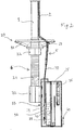
- FIGS 1 and 2 show schematically an embodiment of the arrangement according to the invention.
- the arrangement according to the invention comprises a rock bolt 1 equipped with a longitudinal tube 2 where the tube has a forward first end 3 arranged at the anchoring end 4 of the rock bolt and a second end 5 arranged at the mounting end 6 of the rock bolt.
- the tube has a passage 7 and a wall 8 of the tube, and is attached at the rock bolt 1 with fastening arrangements 9.
- the passage 7 extends between the forward end 3 of the tube and the second end 5 of the tube closest to the mounting end 6 of the rock bolt.
- the arrangement according to the invention comprises also an extended sensor 10 that is introduced into the passage 7 of the tube.
- the sensor 10 consists of a thin loop of electrically conducting material such as wire, which may be of piano wire type, that is introduced into the passage 7 of the tube.
- the sensor 10 has a forward end 11 that is attached at the anchoring end 4 of the rock bolt with a screw joint 12 or similar, in order to form an electrically conducting connection.
- the passage 7 of the tube may be sealed at the forward end 3 through melt sealing of the tube in order to prevent grout 13 entering the passage 7.
- the sensor 10 is designed to be longer than the tube 2 and has a connection end 14 intended to be connected to a monitoring arrangement 15 next to the assembly end 6 of the rock bolt.
- the sensor 10 can be freely displaced inside of the passage 7 of the tube, and is arranged to be parallel with the rock bolt 1. It can in this way follow changes of the rock bolt. If the rock bolt is elongated, therefore, the sensor 10 will react in a corresponding manner and be displaced with the anchoring end 4 of the rock bolt. If the rock bolt 1 breaks as a consequence of increased load in a certain region, also the sensor can, under certain circumstances, break, next to the same region.
- Figures 3 a-d show schematically the embedding of a rock bolt 1 comprising a tube 2 in a borehole 16, through a portion of grout 13 being injected into the borehole 16 by a nozzle 17, normally a tube.
- the borehole 16 is filled from the bottom 18 of the borehole, after which the tube is withdrawn as filling continues.
- the rock bolt 1 is subsequently introduced into the borehole.
- the arrangement according to the invention is illustrated in Figures 1 and 2 in association with a rock bolt 1 of ribbed steel type.
- the rock bolt 1 may be designed also as a cable bolt or a dynamic rock bolt.
- One type of dynamic rock bolt (not shown in the drawings) is provided with one or several surrounding sheaths whose task is to prevent the bolt becoming fixed embedded in grout 13 along its complete length. This leads to the ability of the bolt to be elongated and extended being exploited, whereby the load-absorbing ability of the bolt increases.
- a mounting fitting 20 When the bolt 1 with the tube 2 is introduced into the borehole 16, a mounting fitting 20, a washer 21 with a nut 22, is mounted on the protruding assembly end 16 of the rock bolt closes to the borehole 19. It is preferable that the tube 2 be somewhat longer than the rock bolt 1 and protrudes from the borehole 16.
- the washer 21 of the mounting fitting may be designed with a hole 23 through which the tube 2 with the sensor 10 can be passed.
- Rock material 25 may be constituted in different ways: undiscovered cracks 26 and natural cavities are sometimes present that are filled by an injected portion of the grout 13. This means that the portion of grout that has been injected may be insufficient to fix the rock bolt, which may have as its consequence that the reinforcement system of which the bolt is a part is deficient, and has insufficient load-bearing capacity.
- the rock bolt 1 with the tube is introduced into what appears to be a filled borehole 16, empty spaces or cavities 26 may arise along the bolt that are difficult to detect.
- Such a cavity or cavities 26, usually arises or arise, in particular, at the extreme end, at the deepest part of the borehole. There is in this case the risk that the uppermost part of the bolt is not properly anchored by the grout. If this is the case, a part of the load-bearing capacity of the bolt is lost. Furthermore, the risk for corrosion of the bolt increases, since the rock in itself may be wet.
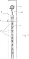
- Figure 4 shows schematically a further embodiment of the arrangement where the wall 8 of the tube 2 is provided with a set of openings 27, cuts or slits, that can be closed and that are initially closed (see Figure 4 ). These can, however, be opened through the supply of medium 30 under pressure to the passage 7 of the tube, in order to detect the presence of a cavity 26 in the borehole.
- the openings 27 may be distributed along the complete length of the tube, but are primarily distributed over the forward end 3 of the tube next to the anchoring end 4 of the bolt.
- the tube 2 is designed with openings 27 for the investigation of the presence of cavities 26, such an investigation is carried out shortly after the bolt has been introduced into the borehole (schematically illustrated in Figure 2d ), in order to determine whether the rock bolt 1 has been correctly embedded and is satisfactorily anchored such that the load-bearing ability of the rock bolt satisfies the desired requirements for load-bearing ability.
- the investigation concerns primarily the investigation of whether the anchoring end 4 of the rock bolt is well embedded.
- a medium 30 under pressure is supplied from measuring equipment 28 that has been temporarily connected for this purpose by connection means 29 to the end 5 of the tube that is closest to the opening 19 of the borehole.
- the arrangement according to the invention comprises also a monitoring arrangement that is mounted at the mounting end 6 of the rock bolt.
- the monitoring arrangement 15 may be designed to be screwed directly onto the thread 24 of the rock bolt with, for example, a nut 32.
- the monitoring arrangement 15 is mounted at the bolt such that an electrically conducting connection is formed, for example through the nut 32. In cases in which an investigation of the anchoring of the rock bolt at the bottom end of the borehole through measurement of the presence of cavities 26 is carried out, the monitoring arrangement 15 is mounted at the bolt after such an investigation.
- FIG. 5 shows one variant of a monitoring arrangement 15 that comprises a detector means 34, an evaluation means 35, a signalling means 36 and a power supply 37.
- the sensor 10 Since the sensor 10 is fixed to the anchoring end 4 of the rock bolt and to the monitoring arrangement 15, the sensor is influenced in a corresponding manner and will in this way be displaced at the same time as the rock bolt is extended. If the rock bolt is elongated and extended, the sensor 10 and the sliding contact 39 are displaced by a corresponding extent, whereby the potentiometer 38 detects a change dU in voltage.
- the detector means 34 comprises also means 41 to detect conduction in the electrically conducting circuit 33 that consists of the bolt 1, the monitoring arrangement 15 and the sensor 10. If the circuit 33 is closed, the detector means 34 indicates this to the evaluation means 35. If the rock bolt 1 is subject to breakage, the circuit 33 becomes open. In the event that conduction is lacking, the detector means indicates that breakage of the bolt has taken place.
- the bolt is elongated and breakage of the bolt occurs when the load-absorbing ability of the bolt is exceeded. Breakage of the bolt opens the circuit 33 and the monitoring arrangement 15 signals this in an appropriate manner. If the rock material 25 around the rock bolt is displaced in the transverse direction, the bolt and the sensor 10 are sheared off in the same region. The sensor can be removed from the tube and measured in order to give an indication of the location of the break.
- the monitoring arrangement comprises also an evaluation means 35 designed for the reception and evaluation of signals 42 from the detector means 34.
- the evaluation means comprises data processors for the processing of incoming signals 42 and the production of output signals 51 with respect to the condition of the bolt and changes in the condition of the signalling means 36.
- Figure 5 shows that the signalling means 36 comprises LEDs 43.1, 43.2 that can emit flashing or steady light signals in different colours.
- the LEDs are arranged clearly visible on the cover 44 of the monitoring arrangement.
- the monitoring arrangement according to Figure 5 is designed to signal several types of change of condition of the rock bolt.
- the signalling means 36 indicates this through a flashing yellow LED 43.1 in order to signal that the rock bolt has been elongated.
- a red LED 43.2 flashes.
- the signalling means 36 can, of course, be varied and adapted to different situations.
- Figure 6 shows a further variant of a monitoring arrangement that differs from the previous monitoring arrangement in that the signalling means comprises communication means 45 for the transmission and/or the reception of signals over wireless networks such as WiFi or over mobile networks to/from a central presentation unit 46 arranged at another location that is remote from the rock bolt and the monitoring arrangement 15.
- the signalling means comprises communication means 45 for the transmission and/or the reception of signals over wireless networks such as WiFi or over mobile networks to/from a central presentation unit 46 arranged at another location that is remote from the rock bolt and the monitoring arrangement 15.
- a smoke detector 50 or other appropriate sensors may be connected to the monitoring arrangement 15 in order to monitor the presence of smoke in the tunnel or mine.
- a further advantage of the monitoring arrangement is that it is possible to reuse it, since it is mounted at the mounting end of the rock bolt and the connection end of the sensor in a manner that allows it to be removed.
Landscapes
- Engineering & Computer Science (AREA)
- Mining & Mineral Resources (AREA)
- Physics & Mathematics (AREA)
- General Life Sciences & Earth Sciences (AREA)
- Structural Engineering (AREA)
- Life Sciences & Earth Sciences (AREA)
- Geochemistry & Mineralogy (AREA)
- Geology (AREA)
- General Physics & Mathematics (AREA)
- Electromagnetism (AREA)
- Force Measurement Appropriate To Specific Purposes (AREA)
- Geophysics And Detection Of Objects (AREA)
- Piles And Underground Anchors (AREA)
Claims (22)
- Anordnung für einen Gebirgsanker (1), der ausgelegt ist, um in Mörtel in einem Bohrloch (16) eingebettet zu werden, wobei der Gebirgsanker (1) mit einem länglichen Rohr (2) mit einem Durchgang (7) und einer Überwachungsvorrichtung (15) zur Verbindung mit dem Gebirgsanker (1) ausgestaltet ist, dadurch gekennzeichnet, dass ein länglicher, elektrisch leitender Sensor (10), der in den Durchgang (7) des Rohrs eingeführt ist, und dass der Sensor (10) mit einem verankernden Ende (4) des Gebirgsankers verbunden ist, um eine elektrisch leitende Verbindung zu bilden, dass eine elektrisch leitende Schaltung (33) durch die Verbindung des Gebirgsankers (1), des Sensors (10) und der Überwachungsvorrichtung (15) gebildet ist, und dass die Überwachungsvorrichtung Auswertemittel (35), die zum Auswerten des Vorhandenseins von Änderungen des Zustandes des Ankers ausgelegt sind, und Signalisierungsmittel (36), die zur Signalisierung des Zustandes des Ankers (1) ausgestaltet sind, aufweist.
- Anordnung für einen Gebirgsanker nach Anspruch 1, wobei das Rohr (2) eine Wandung (8) aufweist, die mit durchdringenden Öffnungen (27) zum Detektieren des Vorhandenseins eines Hohlraums (26) versehen ist.
- Anordnung für einen Gebirgsanker nach einem der Ansprüche 1-2, wobei die Überwachungsvorrichtung (15) zur Montage an einem Montageende (6) des Gebirgankers ausgestaltet ist.
- Anordnung für einen Gebirgsanker nach einem der Ansprüche 1-3, umfassend ein Detektierungsmittel (34), das für das Detektieren von Änderungen der Position des Sensors (10) ausgestaltet ist.
- Anordnung für einen Gebirgsanker nach einem der Ansprüche 1-4, umfassend ein Detektierungsmittel (34), das für das Detektieren, ob die Schaltung (33) geschlossen ist, ausgestaltet ist.
- Anordnung für einen Gebirgsanker nach Anspruch 4 oder 5, wobei das Detektierungsmittel (34) ein mit einem Schleifkontakt (39) versehenes gleitendes Potentiometer (38) umfasst, wobei der Sensor (10) mit einem Schleifkontakt (39) verbunden ist.
- Anordnung für einen Gebirgsanker nach einem der Ansprüche 1-6, wobei der Sensor (10) ein Gewinde oder einen Draht umfasst.
- Anordnung für einen Gebirgsanker nach einem der Ansprüche 1-7, wobei das Signalisierungsmittel (36) Leuchtdioden (43.1; 43.2) umfasst, die an einem Deckel (44) der Überwachungsvorrichtung angeordnet sind.
- Anordnung für einen Gebirgsanker nach einem der Ansprüche 1-8, wobei das Signalisierungsmittel (36) ein Kommunikationsmittel (45) zum Übertragen und/oder Empfangen von Signalen (46, 47, 48, 49) über Drahtlosnetzwerke oder Mobilfunknetze an eine zentrale Darstellungseinheit umfasst.
- Anordnung für einen Gebirgsanker nach einem der Ansprüche 1-9, wobei die Überwachungsvorrichtung (15) ausgestaltet ist, um an dem Montageende (6) des Gebirgankers in einer abnehmbaren Weise montiert zu werden.
- Anordnung für einen Gebirgsanker nach einem der Ansprüche 1 -10, wobei der Gebirgsanker (1) als ein dynamischer Gebirgsanker ausgebildet ist, der einen umgebenden Mantel entlang von einem Teil des Gebirgsankers (1) umfasst.
- Anordnung für einen Gebirgsanker nach einem der Ansprüche 1-11, wobei die Überwachungsvorrichtung (15) einen Rauchmelder 50 umfasst.
- Verfahren zur Verwendung einer Anordnung für einen Gebirgsanker (1) nach Anspruch 1, umfassend die folgenden Schritte:Einführen eines Sensors (10) in ein Rohr (2), das an dem Gebirgsanker (1) befestigt ist,Verbinden des Sensors (10) mit dem verankernden Ende des Gebirgsankers, Einführen des Gebirgsankers (1) in das mit Mörtel (13) gefüllte Bohrloch (16), Verbinden einer Überwachungsvorrichtung (15) mit dem Gebirgsanker (1), Verbinden des Gebirgsankers (1), des Sensors (10) und der Überwachungsvorrichtung (15),um eine elektrisch leitende Schaltung (33) zu bilden, undAuswerten des Auftretens von Änderungen des Zustandes des Ankers durch ein Auswertemittel (35), und Signalisieren des Zustandes des Gebirgankers durch das Signalisierungsmittel (36).
- Verfahren nach Anspruch 13, umfassend den Schritt des Detektierens des Vorhandenseins eines Hohlraums (26) durch die Versorgung eines druckbeaufschlagten Mediums (30) an das Rohr (2) und Detektieren einer Druckänderung des Mediums oder einer Strömung eines Mediums.
- Verfahren nach einem der Ansprüche 13-14, umfassend das Detektieren von Änderungen der Position des Sensors (10).
- Verfahren nach einem der Ansprüche 13-15, umfassend ein Signalisieren beim Detektieren einer Verlängerung e des Gebirgsankers.
- Verfahren nach einem der Ansprüche 13-16, umfassend ein Signalisieren, wenn die Änderung der Position des Sensors (10) einen vorgegebenen maximalen Verschiebungsabstand smax überschreitet.
- Verfahren nach einem der Ansprüche 13-17, umfassend das Detektieren von Leitung in der Schaltung (33), wobei eine fehlende Leitung einen Bruch des Ankers anzeigt.
- Verfahren nach einem der Ansprüche 13-18, umfassend ein Signalisieren durch das Signalisierungsmittel (36) beim Detektieren eines Bruchs des Gebirgsankers.
- Verfahren nach einem der Ansprüche 13-19, wobei das Signalisieren die Emission von Blinklicht- und/oder Dauerlichtsignalen an auf dem Deckel (44) der Überwachungsvorrichtung angeordneten LEDs (43) umfasst.
- Verfahren nach einem der Ansprüche 13-20, wobei das Signalisieren das Übertragen und/oder Empfangen von Signalen über drahtlose WiFi-Netzwerke oder Mobilfunknetze an eine zentrale Darstellungseinheit umfasst.
- Ankerverstärkungssystem umfassend einen Satz von mehreren Gebirgsankern, wobei jeder der Anker (1) mit einer Anordnung nach einem der Ansprüche 1-12 ausgestattet ist.
Applications Claiming Priority (2)
| Application Number | Priority Date | Filing Date | Title |
|---|---|---|---|
| SE1451357A SE538499C2 (sv) | 2014-11-13 | 2014-11-13 | Anordning för bergbult och förfarande för användning av anordningen samt förstärkningssystem innefattande sådan anordning. |
| PCT/SE2015/051215 WO2016076788A1 (en) | 2014-11-13 | 2015-11-13 | Arrangement for rock bolts and a method for the use of the arrangement, and a reinforcement system comprising such an arrangement |
Publications (3)
| Publication Number | Publication Date |
|---|---|
| EP3218580A1 EP3218580A1 (de) | 2017-09-20 |
| EP3218580A4 EP3218580A4 (de) | 2018-07-11 |
| EP3218580B1 true EP3218580B1 (de) | 2019-10-16 |
Family
ID=55954730
Family Applications (1)
| Application Number | Title | Priority Date | Filing Date |
|---|---|---|---|
| EP15859518.1A Active EP3218580B1 (de) | 2014-11-13 | 2015-11-13 | Anordnung für gebirgsanker und verfahren zur verwendung der anordnung sowie ein verstärkungssystem mit einer derartigen anordnung |
Country Status (7)
| Country | Link |
|---|---|
| US (1) | US10370969B2 (de) |
| EP (1) | EP3218580B1 (de) |
| AU (1) | AU2015347369B2 (de) |
| CA (1) | CA2967566C (de) |
| CL (1) | CL2017001226A1 (de) |
| SE (1) | SE538499C2 (de) |
| WO (1) | WO2016076788A1 (de) |
Cited By (1)
| Publication number | Priority date | Publication date | Assignee | Title |
|---|---|---|---|---|
| WO2025014413A1 (en) * | 2023-07-07 | 2025-01-16 | Thingwave Ab | Devices and methods for determining integrity of elongated metallic bars |
Families Citing this family (15)
| Publication number | Priority date | Publication date | Assignee | Title |
|---|---|---|---|---|
| IT201700037754A1 (it) * | 2017-04-06 | 2018-10-06 | Thur Srl | Procedimento per migliorare le caratteristiche meccaniche ed idrauliche dei terreni. |
| WO2020231321A1 (en) | 2019-05-15 | 2020-11-19 | Thingwave Ab | Device and method for measuring deformation in metallic bars |
| US11707010B2 (en) | 2019-06-14 | 2023-07-25 | Cnh Industrial America Llc | System and method for monitoring the operational status of tools of an agricultural implement |
| US11105199B2 (en) | 2019-09-11 | 2021-08-31 | Square Cut Systems, LLC | System and method for supporting sidewalls or ribs in coal mines |
| US11408284B2 (en) | 2019-09-11 | 2022-08-09 | Square Cut Systems, LLC | System and method for supporting sidewalls or ribs in coal mines |
| US11015993B2 (en) | 2019-10-02 | 2021-05-25 | Cnh Industrial America Llc | System and method for wirelessly monitoring the operational status of tools of an agricultural implement |
| US11506723B2 (en) | 2019-10-02 | 2022-11-22 | Cnh Industrial America Llc | System and method for monitoring the operational status of tools of an agricultural implement utilizing connectivity |
| CN111075487B (zh) * | 2019-12-31 | 2024-05-24 | 西南石油大学 | 具有测定围岩应变与温度耦合功能的锚杆 |
| CN111256879A (zh) * | 2020-03-20 | 2020-06-09 | 中铁工程装备集团有限公司 | 一种锚杆轴力可视化监测预警装置及其监测预警方法 |
| CN112796811A (zh) * | 2021-01-07 | 2021-05-14 | 招商局重庆公路工程检测中心有限公司 | 一种锚杆数量检测装置 |
| EP4295015B1 (de) * | 2021-02-19 | 2024-10-23 | Rocbolt Technolgies (Pty) Ltd. | Gebirgsankeranordnung mit indikator |
| US12150397B2 (en) | 2021-03-19 | 2024-11-26 | Cnh Industrial America Llc | System and method for monitoring an operational status of a shear pin for a ground-engaging assembly of an agricultural implement |
| WO2022251887A1 (en) * | 2021-05-28 | 2022-12-01 | Innovative Mining Products (Pty)Ltd | Modified spherical seat for a rock bolt assembly |
| AT525566B1 (de) * | 2021-11-17 | 2023-05-15 | Dsi Underground Austria Gmbh | Sensorgestütztes hohlstab-system |
| EP4703557A1 (de) * | 2024-08-27 | 2026-03-04 | Montanuniversität Leoben | Adapter für fels- oder gebäudeankersystem |
Family Cites Families (17)
| Publication number | Priority date | Publication date | Assignee | Title |
|---|---|---|---|---|
| GB1025729A (en) * | 1963-11-06 | 1966-04-14 | Chester Irving Williams | Rock bolt assembly |
| SU533769A1 (ru) | 1975-05-11 | 1976-10-30 | Предприятие П/Я Г-4488 | Способ соединени металлической рубашки с валом |
| GB2199952A (en) * | 1987-01-16 | 1988-07-20 | Coal Ind | Method and apparatus for measuring load on a rock bolt |
| US5430953A (en) * | 1993-02-18 | 1995-07-11 | Queen's University At Kingston | Apparatus for detecting or measuring movements in geological formations and other massive structures |
| CA2200834C (en) * | 1997-03-24 | 2000-05-02 | Canadian Mining Industry Research Organization - Organisation De De L'industrie Miniere Canadienne | Stress measuring rock support device |
| US6311564B1 (en) * | 1998-02-27 | 2001-11-06 | The United States Of America As Represented By The Department Of Health And Human Services | Support apparatus with stress measuring capability |
| JP2001318011A (ja) * | 2000-05-02 | 2001-11-16 | Toa Grout Kogyo Co Ltd | 引張鋼材の歪みまたは張力測定方法 |
| WO2003069122A2 (en) * | 2001-12-31 | 2003-08-21 | The Government Of The United States Of America As Represented By The Secretary, Department Of Health | Strain detection in rock bolts |
| ZA200405176B (en) * | 2003-06-30 | 2005-04-26 | Csir | Method and apparatus for testing installation quality in a grouted anchor system |
| SE528911C2 (sv) * | 2005-01-19 | 2007-03-13 | Atlas Copco Rock Drills Ab | Förfarande och system för övervakning och dokumentering av installation av bergförstärkningsbult |
| JP2006250647A (ja) * | 2005-03-09 | 2006-09-21 | Jfe Koken Corp | ワイヤケーブル、並びに張力測定システム及び張力測定方法 |
| EP2232014A1 (de) * | 2007-12-21 | 2010-09-29 | Alminco Pty Ltd | Selbstbohrende gebirgsverankerung |
| WO2009104687A1 (ja) * | 2008-02-20 | 2009-08-27 | 国立大学法人神戸大学 | 線材の変状検知装置 |
| SE533769C2 (sv) | 2009-05-06 | 2010-12-28 | Malmfaelten Ab | Förfarande, system, användning av system jämte förstärkningsorgan vid bergförstärkning |
| CL2011000042A1 (es) * | 2011-01-07 | 2011-06-17 | Sistema de fortificacion que comprende una barra helicoidal estandar, una cabeza de expansion adaptada a la rosca de la barra, un elemento de material plastico, un tubo de plastico corrugado, una placa de fortificacion estandar y una tuerca de fortificacion roscada segun el perno helicoidal que utiliza. | |
| SE537019C2 (sv) | 2013-02-28 | 2014-12-02 | Malmfälten I Norr Ab | Anordning för detektering av förekomst av en eller flera kaviteter i ett borrhål |
| CN103470287B (zh) | 2013-09-09 | 2015-11-25 | 中铁西北科学研究院有限公司深圳南方分院 | 一种可测深注浆管及测深方法 |
-
2014
- 2014-11-13 SE SE1451357A patent/SE538499C2/sv unknown
-
2015
- 2015-11-13 WO PCT/SE2015/051215 patent/WO2016076788A1/en not_active Ceased
- 2015-11-13 EP EP15859518.1A patent/EP3218580B1/de active Active
- 2015-11-13 CA CA2967566A patent/CA2967566C/en active Active
- 2015-11-13 US US15/526,705 patent/US10370969B2/en active Active
- 2015-11-13 AU AU2015347369A patent/AU2015347369B2/en active Active
-
2017
- 2017-05-12 CL CL2017001226A patent/CL2017001226A1/es unknown
Non-Patent Citations (1)
| Title |
|---|
| None * |
Cited By (1)
| Publication number | Priority date | Publication date | Assignee | Title |
|---|---|---|---|---|
| WO2025014413A1 (en) * | 2023-07-07 | 2025-01-16 | Thingwave Ab | Devices and methods for determining integrity of elongated metallic bars |
Also Published As
| Publication number | Publication date |
|---|---|
| EP3218580A4 (de) | 2018-07-11 |
| EP3218580A1 (de) | 2017-09-20 |
| US20170321552A1 (en) | 2017-11-09 |
| AU2015347369B2 (en) | 2020-05-14 |
| SE1451357A1 (sv) | 2016-05-14 |
| CA2967566A1 (en) | 2016-05-19 |
| US10370969B2 (en) | 2019-08-06 |
| CL2017001226A1 (es) | 2018-02-02 |
| WO2016076788A1 (en) | 2016-05-19 |
| SE538499C2 (sv) | 2016-08-09 |
| CA2967566C (en) | 2023-05-23 |
| AU2015347369A1 (en) | 2017-06-15 |
Similar Documents
| Publication | Publication Date | Title |
|---|---|---|
| EP3218580B1 (de) | Anordnung für gebirgsanker und verfahren zur verwendung der anordnung sowie ein verstärkungssystem mit einer derartigen anordnung | |
| EP2954163B1 (de) | Gebirgsanker | |
| KR101043746B1 (ko) | 지반감시유닛 및 이를 포함하는 지반보강장치 | |
| EP2427633B1 (de) | Verfahren, system, verwendung des system und verstärkungselement für felsverstärkung | |
| CN102877870A (zh) | 动静组合智能预警锚杆 | |
| US9784718B2 (en) | Method and apparatus for detection of structural failure | |
| US20120227507A1 (en) | Instrumented coupler load cell for rock anchors | |
| CN106958459A (zh) | 一种巷道顶板失稳分级预警装置及预警方法 | |
| US20220214157A1 (en) | Device and method for measuring deformation in metallic bars | |
| CN116448050B (zh) | 一种用于滑坡变形的监测装置及监测方法 | |
| CN202832596U (zh) | 动静组合智能预警锚杆 | |
| KR20110035499A (ko) | 하중측정 감도가 우수한 어스 앵커용 로드 셀 | |
| CN108843361A (zh) | 一种防水型测力锚杆 | |
| CN107288670A (zh) | 一种对巷道进行支护的支护方法 | |
| CN107561161A (zh) | 一种煤矿老顶破断卸压的预警方法 | |
| CN116804376A (zh) | 一种具有多级吸能机制的钢带及其让压梁受力变形监测系统和监测方法 | |
| AU2024294211A1 (en) | Devices and methods for determining integrity of elongated metallic bars | |
| EP2961928B1 (de) | Vorrichtung zum erkennen der anwesenheit eines oder mehrerer hohlräume in einem bohrloch | |
| KR20200044332A (ko) | 록볼트 장치 | |
| WO2025014414A1 (en) | Devices, systems and mounting methods for facilitating pre-tensioning of a rock bolt to a structure | |
| CN205934933U (zh) | 一种锚墩结构 | |
| CN220872688U (zh) | 基于微震与电法耦合的放顶煤安全开采监测系统 | |
| CN113482686B (zh) | 一种应力监测系统、巷道及其施工方法 | |
| Mishra et al. | Design of strata deformation indicator for underground openings | |
| CN118533235A (zh) | 一种顶板离层量与锚杆垂直载荷综合监测装置及工作方法 |
Legal Events
| Date | Code | Title | Description |
|---|---|---|---|
| STAA | Information on the status of an ep patent application or granted ep patent |
Free format text: STATUS: THE INTERNATIONAL PUBLICATION HAS BEEN MADE |
|
| PUAI | Public reference made under article 153(3) epc to a published international application that has entered the european phase |
Free format text: ORIGINAL CODE: 0009012 |
|
| STAA | Information on the status of an ep patent application or granted ep patent |
Free format text: STATUS: REQUEST FOR EXAMINATION WAS MADE |
|
| 17P | Request for examination filed |
Effective date: 20170607 |
|
| AK | Designated contracting states |
Kind code of ref document: A1 Designated state(s): AL AT BE BG CH CY CZ DE DK EE ES FI FR GB GR HR HU IE IS IT LI LT LU LV MC MK MT NL NO PL PT RO RS SE SI SK SM TR |
|
| AX | Request for extension of the european patent |
Extension state: BA ME |
|
| DAV | Request for validation of the european patent (deleted) | ||
| DAX | Request for extension of the european patent (deleted) | ||
| A4 | Supplementary search report drawn up and despatched |
Effective date: 20180612 |
|
| RIC1 | Information provided on ipc code assigned before grant |
Ipc: E21D 21/02 20060101AFI20180604BHEP Ipc: G01L 5/00 20060101ALI20180604BHEP Ipc: E21D 20/02 20060101ALI20180604BHEP |
|
| GRAP | Despatch of communication of intention to grant a patent |
Free format text: ORIGINAL CODE: EPIDOSNIGR1 |
|
| STAA | Information on the status of an ep patent application or granted ep patent |
Free format text: STATUS: GRANT OF PATENT IS INTENDED |
|
| INTG | Intention to grant announced |
Effective date: 20190506 |
|
| GRAS | Grant fee paid |
Free format text: ORIGINAL CODE: EPIDOSNIGR3 |
|
| GRAA | (expected) grant |
Free format text: ORIGINAL CODE: 0009210 |
|
| STAA | Information on the status of an ep patent application or granted ep patent |
Free format text: STATUS: THE PATENT HAS BEEN GRANTED |
|
| RAP1 | Party data changed (applicant data changed or rights of an application transferred) |
Owner name: ROCK SAFETY SWEDEN AB |
|
| AK | Designated contracting states |
Kind code of ref document: B1 Designated state(s): AL AT BE BG CH CY CZ DE DK EE ES FI FR GB GR HR HU IE IS IT LI LT LU LV MC MK MT NL NO PL PT RO RS SE SI SK SM TR |
|
| REG | Reference to a national code |
Ref country code: GB Ref legal event code: FG4D |
|
| REG | Reference to a national code |
Ref country code: CH Ref legal event code: EP |
|
| REG | Reference to a national code |
Ref country code: DE Ref legal event code: R096 Ref document number: 602015040046 Country of ref document: DE |
|
| REG | Reference to a national code |
Ref country code: IE Ref legal event code: FG4D |
|
| REG | Reference to a national code |
Ref country code: AT Ref legal event code: REF Ref document number: 1191438 Country of ref document: AT Kind code of ref document: T Effective date: 20191115 |
|
| REG | Reference to a national code |
Ref country code: FI Ref legal event code: FGE |
|
| REG | Reference to a national code |
Ref country code: NL Ref legal event code: MP Effective date: 20191016 |
|
| REG | Reference to a national code |
Ref country code: NO Ref legal event code: T2 Effective date: 20191016 |
|
| REG | Reference to a national code |
Ref country code: LT Ref legal event code: MG4D |
|
| REG | Reference to a national code |
Ref country code: AT Ref legal event code: MK05 Ref document number: 1191438 Country of ref document: AT Kind code of ref document: T Effective date: 20191016 |
|
| PG25 | Lapsed in a contracting state [announced via postgrant information from national office to epo] |
Ref country code: PT Free format text: LAPSE BECAUSE OF FAILURE TO SUBMIT A TRANSLATION OF THE DESCRIPTION OR TO PAY THE FEE WITHIN THE PRESCRIBED TIME-LIMIT Effective date: 20200217 Ref country code: BG Free format text: LAPSE BECAUSE OF FAILURE TO SUBMIT A TRANSLATION OF THE DESCRIPTION OR TO PAY THE FEE WITHIN THE PRESCRIBED TIME-LIMIT Effective date: 20200116 Ref country code: GR Free format text: LAPSE BECAUSE OF FAILURE TO SUBMIT A TRANSLATION OF THE DESCRIPTION OR TO PAY THE FEE WITHIN THE PRESCRIBED TIME-LIMIT Effective date: 20200117 Ref country code: LV Free format text: LAPSE BECAUSE OF FAILURE TO SUBMIT A TRANSLATION OF THE DESCRIPTION OR TO PAY THE FEE WITHIN THE PRESCRIBED TIME-LIMIT Effective date: 20191016 Ref country code: SE Free format text: LAPSE BECAUSE OF FAILURE TO SUBMIT A TRANSLATION OF THE DESCRIPTION OR TO PAY THE FEE WITHIN THE PRESCRIBED TIME-LIMIT Effective date: 20191016 Ref country code: AT Free format text: LAPSE BECAUSE OF FAILURE TO SUBMIT A TRANSLATION OF THE DESCRIPTION OR TO PAY THE FEE WITHIN THE PRESCRIBED TIME-LIMIT Effective date: 20191016 Ref country code: PL Free format text: LAPSE BECAUSE OF FAILURE TO SUBMIT A TRANSLATION OF THE DESCRIPTION OR TO PAY THE FEE WITHIN THE PRESCRIBED TIME-LIMIT Effective date: 20191016 Ref country code: NL Free format text: LAPSE BECAUSE OF FAILURE TO SUBMIT A TRANSLATION OF THE DESCRIPTION OR TO PAY THE FEE WITHIN THE PRESCRIBED TIME-LIMIT Effective date: 20191016 Ref country code: LT Free format text: LAPSE BECAUSE OF FAILURE TO SUBMIT A TRANSLATION OF THE DESCRIPTION OR TO PAY THE FEE WITHIN THE PRESCRIBED TIME-LIMIT Effective date: 20191016 |
|
| PG25 | Lapsed in a contracting state [announced via postgrant information from national office to epo] |
Ref country code: IS Free format text: LAPSE BECAUSE OF FAILURE TO SUBMIT A TRANSLATION OF THE DESCRIPTION OR TO PAY THE FEE WITHIN THE PRESCRIBED TIME-LIMIT Effective date: 20200224 Ref country code: HR Free format text: LAPSE BECAUSE OF FAILURE TO SUBMIT A TRANSLATION OF THE DESCRIPTION OR TO PAY THE FEE WITHIN THE PRESCRIBED TIME-LIMIT Effective date: 20191016 Ref country code: RS Free format text: LAPSE BECAUSE OF FAILURE TO SUBMIT A TRANSLATION OF THE DESCRIPTION OR TO PAY THE FEE WITHIN THE PRESCRIBED TIME-LIMIT Effective date: 20191016 |
|
| REG | Reference to a national code |
Ref country code: DE Ref legal event code: R119 Ref document number: 602015040046 Country of ref document: DE |
|
| PG25 | Lapsed in a contracting state [announced via postgrant information from national office to epo] |
Ref country code: AL Free format text: LAPSE BECAUSE OF FAILURE TO SUBMIT A TRANSLATION OF THE DESCRIPTION OR TO PAY THE FEE WITHIN THE PRESCRIBED TIME-LIMIT Effective date: 20191016 |
|
| REG | Reference to a national code |
Ref country code: CH Ref legal event code: PL |
|
| PG2D | Information on lapse in contracting state deleted |
Ref country code: IS |
|
| PG25 | Lapsed in a contracting state [announced via postgrant information from national office to epo] |
Ref country code: DK Free format text: LAPSE BECAUSE OF FAILURE TO SUBMIT A TRANSLATION OF THE DESCRIPTION OR TO PAY THE FEE WITHIN THE PRESCRIBED TIME-LIMIT Effective date: 20191016 Ref country code: EE Free format text: LAPSE BECAUSE OF FAILURE TO SUBMIT A TRANSLATION OF THE DESCRIPTION OR TO PAY THE FEE WITHIN THE PRESCRIBED TIME-LIMIT Effective date: 20191016 Ref country code: LU Free format text: LAPSE BECAUSE OF NON-PAYMENT OF DUE FEES Effective date: 20191113 Ref country code: RO Free format text: LAPSE BECAUSE OF FAILURE TO SUBMIT A TRANSLATION OF THE DESCRIPTION OR TO PAY THE FEE WITHIN THE PRESCRIBED TIME-LIMIT Effective date: 20191016 Ref country code: CZ Free format text: LAPSE BECAUSE OF FAILURE TO SUBMIT A TRANSLATION OF THE DESCRIPTION OR TO PAY THE FEE WITHIN THE PRESCRIBED TIME-LIMIT Effective date: 20191016 Ref country code: ES Free format text: LAPSE BECAUSE OF FAILURE TO SUBMIT A TRANSLATION OF THE DESCRIPTION OR TO PAY THE FEE WITHIN THE PRESCRIBED TIME-LIMIT Effective date: 20191016 Ref country code: MC Free format text: LAPSE BECAUSE OF FAILURE TO SUBMIT A TRANSLATION OF THE DESCRIPTION OR TO PAY THE FEE WITHIN THE PRESCRIBED TIME-LIMIT Effective date: 20191016 Ref country code: LI Free format text: LAPSE BECAUSE OF NON-PAYMENT OF DUE FEES Effective date: 20191130 Ref country code: CH Free format text: LAPSE BECAUSE OF NON-PAYMENT OF DUE FEES Effective date: 20191130 Ref country code: IS Free format text: LAPSE BECAUSE OF FAILURE TO SUBMIT A TRANSLATION OF THE DESCRIPTION OR TO PAY THE FEE WITHIN THE PRESCRIBED TIME-LIMIT Effective date: 20200216 |
|
| PLBE | No opposition filed within time limit |
Free format text: ORIGINAL CODE: 0009261 |
|
| REG | Reference to a national code |
Ref country code: BE Ref legal event code: MM Effective date: 20191130 |
|
| STAA | Information on the status of an ep patent application or granted ep patent |
Free format text: STATUS: NO OPPOSITION FILED WITHIN TIME LIMIT |
|
| PG25 | Lapsed in a contracting state [announced via postgrant information from national office to epo] |
Ref country code: SM Free format text: LAPSE BECAUSE OF FAILURE TO SUBMIT A TRANSLATION OF THE DESCRIPTION OR TO PAY THE FEE WITHIN THE PRESCRIBED TIME-LIMIT Effective date: 20191016 Ref country code: IT Free format text: LAPSE BECAUSE OF FAILURE TO SUBMIT A TRANSLATION OF THE DESCRIPTION OR TO PAY THE FEE WITHIN THE PRESCRIBED TIME-LIMIT Effective date: 20191016 Ref country code: SK Free format text: LAPSE BECAUSE OF FAILURE TO SUBMIT A TRANSLATION OF THE DESCRIPTION OR TO PAY THE FEE WITHIN THE PRESCRIBED TIME-LIMIT Effective date: 20191016 |
|
| 26N | No opposition filed |
Effective date: 20200717 |
|
| GBPC | Gb: european patent ceased through non-payment of renewal fee |
Effective date: 20200116 |
|
| PG25 | Lapsed in a contracting state [announced via postgrant information from national office to epo] |
Ref country code: FR Free format text: LAPSE BECAUSE OF NON-PAYMENT OF DUE FEES Effective date: 20191216 Ref country code: GB Free format text: LAPSE BECAUSE OF NON-PAYMENT OF DUE FEES Effective date: 20200116 Ref country code: IE Free format text: LAPSE BECAUSE OF NON-PAYMENT OF DUE FEES Effective date: 20191113 Ref country code: DE Free format text: LAPSE BECAUSE OF NON-PAYMENT OF DUE FEES Effective date: 20200603 |
|
| PG25 | Lapsed in a contracting state [announced via postgrant information from national office to epo] |
Ref country code: BE Free format text: LAPSE BECAUSE OF NON-PAYMENT OF DUE FEES Effective date: 20191130 Ref country code: SI Free format text: LAPSE BECAUSE OF FAILURE TO SUBMIT A TRANSLATION OF THE DESCRIPTION OR TO PAY THE FEE WITHIN THE PRESCRIBED TIME-LIMIT Effective date: 20191016 |
|
| PG25 | Lapsed in a contracting state [announced via postgrant information from national office to epo] |
Ref country code: CY Free format text: LAPSE BECAUSE OF FAILURE TO SUBMIT A TRANSLATION OF THE DESCRIPTION OR TO PAY THE FEE WITHIN THE PRESCRIBED TIME-LIMIT Effective date: 20191016 |
|
| PG25 | Lapsed in a contracting state [announced via postgrant information from national office to epo] |
Ref country code: HU Free format text: LAPSE BECAUSE OF FAILURE TO SUBMIT A TRANSLATION OF THE DESCRIPTION OR TO PAY THE FEE WITHIN THE PRESCRIBED TIME-LIMIT; INVALID AB INITIO Effective date: 20151113 Ref country code: MT Free format text: LAPSE BECAUSE OF FAILURE TO SUBMIT A TRANSLATION OF THE DESCRIPTION OR TO PAY THE FEE WITHIN THE PRESCRIBED TIME-LIMIT Effective date: 20191016 |
|
| PG25 | Lapsed in a contracting state [announced via postgrant information from national office to epo] |
Ref country code: TR Free format text: LAPSE BECAUSE OF FAILURE TO SUBMIT A TRANSLATION OF THE DESCRIPTION OR TO PAY THE FEE WITHIN THE PRESCRIBED TIME-LIMIT Effective date: 20191016 |
|
| PG25 | Lapsed in a contracting state [announced via postgrant information from national office to epo] |
Ref country code: MK Free format text: LAPSE BECAUSE OF FAILURE TO SUBMIT A TRANSLATION OF THE DESCRIPTION OR TO PAY THE FEE WITHIN THE PRESCRIBED TIME-LIMIT Effective date: 20191016 |
|
| PGFP | Annual fee paid to national office [announced via postgrant information from national office to epo] |
Ref country code: FI Payment date: 20250922 Year of fee payment: 11 |
|
| PGFP | Annual fee paid to national office [announced via postgrant information from national office to epo] |
Ref country code: NO Payment date: 20251017 Year of fee payment: 11 |