EP3218629B1 - Verfahren zur installation eines unverbundenen flexiblen rohrs - Google Patents
Verfahren zur installation eines unverbundenen flexiblen rohrs Download PDFInfo
- Publication number
- EP3218629B1 EP3218629B1 EP15858692.5A EP15858692A EP3218629B1 EP 3218629 B1 EP3218629 B1 EP 3218629B1 EP 15858692 A EP15858692 A EP 15858692A EP 3218629 B1 EP3218629 B1 EP 3218629B1
- Authority
- EP
- European Patent Office
- Prior art keywords
- annulus
- corrosion
- promoting liquid
- corrosion promoting
- flexible pipe
- Prior art date
- Legal status (The legal status is an assumption and is not a legal conclusion. Google has not performed a legal analysis and makes no representation as to the accuracy of the status listed.)
- Active
Links
Images



Classifications
-
- E—FIXED CONSTRUCTIONS
- E21—EARTH OR ROCK DRILLING; MINING
- E21B—EARTH OR ROCK DRILLING; OBTAINING OIL, GAS, WATER, SOLUBLE OR MELTABLE MATERIALS OR A SLURRY OF MINERALS FROM WELLS
- E21B19/00—Handling rods, casings, tubes or the like outside the borehole, e.g. in the derrick; Apparatus for feeding the rods or cables
- E21B19/22—Handling reeled pipe or rod units, e.g. flexible drilling pipes
-
- C—CHEMISTRY; METALLURGY
- C23—COATING METALLIC MATERIAL; COATING MATERIAL WITH METALLIC MATERIAL; CHEMICAL SURFACE TREATMENT; DIFFUSION TREATMENT OF METALLIC MATERIAL; COATING BY VACUUM EVAPORATION, BY SPUTTERING, BY ION IMPLANTATION OR BY CHEMICAL VAPOUR DEPOSITION, IN GENERAL; INHIBITING CORROSION OF METALLIC MATERIAL OR INCRUSTATION IN GENERAL
- C23F—NON-MECHANICAL REMOVAL OF METALLIC MATERIAL FROM SURFACE; INHIBITING CORROSION OF METALLIC MATERIAL OR INCRUSTATION IN GENERAL; MULTI-STEP PROCESSES FOR SURFACE TREATMENT OF METALLIC MATERIAL INVOLVING AT LEAST ONE PROCESS PROVIDED FOR IN CLASS C23 AND AT LEAST ONE PROCESS COVERED BY SUBCLASS C21D OR C22F OR CLASS C25
- C23F13/00—Inhibiting corrosion of metals by anodic or cathodic protection
-
- E—FIXED CONSTRUCTIONS
- E21—EARTH OR ROCK DRILLING; MINING
- E21B—EARTH OR ROCK DRILLING; OBTAINING OIL, GAS, WATER, SOLUBLE OR MELTABLE MATERIALS OR A SLURRY OF MINERALS FROM WELLS
- E21B17/00—Drilling rods or pipes; Flexible drill strings; Kellies; Drill collars; Sucker rods; Cables; Casings; Tubings
- E21B17/01—Risers
-
- F—MECHANICAL ENGINEERING; LIGHTING; HEATING; WEAPONS; BLASTING
- F16—ENGINEERING ELEMENTS AND UNITS; GENERAL MEASURES FOR PRODUCING AND MAINTAINING EFFECTIVE FUNCTIONING OF MACHINES OR INSTALLATIONS; THERMAL INSULATION IN GENERAL
- F16L—PIPES; JOINTS OR FITTINGS FOR PIPES; SUPPORTS FOR PIPES, CABLES OR PROTECTIVE TUBING; MEANS FOR THERMAL INSULATION IN GENERAL
- F16L1/00—Laying or reclaiming pipes; Repairing or joining pipes on or under water
- F16L1/12—Laying or reclaiming pipes on or under water
- F16L1/14—Laying or reclaiming pipes on or under water between the surface and the bottom
- F16L1/15—Laying or reclaiming pipes on or under water between the surface and the bottom vertically
-
- F—MECHANICAL ENGINEERING; LIGHTING; HEATING; WEAPONS; BLASTING
- F16—ENGINEERING ELEMENTS AND UNITS; GENERAL MEASURES FOR PRODUCING AND MAINTAINING EFFECTIVE FUNCTIONING OF MACHINES OR INSTALLATIONS; THERMAL INSULATION IN GENERAL
- F16L—PIPES; JOINTS OR FITTINGS FOR PIPES; SUPPORTS FOR PIPES, CABLES OR PROTECTIVE TUBING; MEANS FOR THERMAL INSULATION IN GENERAL
- F16L11/00—Hoses, i.e. flexible pipes
- F16L11/04—Hoses, i.e. flexible pipes made of rubber or flexible plastics
- F16L11/08—Hoses, i.e. flexible pipes made of rubber or flexible plastics with reinforcements embedded in the wall
- F16L11/081—Hoses, i.e. flexible pipes made of rubber or flexible plastics with reinforcements embedded in the wall comprising one or more layers of a helically wound cord or wire
-
- F—MECHANICAL ENGINEERING; LIGHTING; HEATING; WEAPONS; BLASTING
- F16—ENGINEERING ELEMENTS AND UNITS; GENERAL MEASURES FOR PRODUCING AND MAINTAINING EFFECTIVE FUNCTIONING OF MACHINES OR INSTALLATIONS; THERMAL INSULATION IN GENERAL
- F16L—PIPES; JOINTS OR FITTINGS FOR PIPES; SUPPORTS FOR PIPES, CABLES OR PROTECTIVE TUBING; MEANS FOR THERMAL INSULATION IN GENERAL
- F16L11/00—Hoses, i.e. flexible pipes
- F16L11/04—Hoses, i.e. flexible pipes made of rubber or flexible plastics
- F16L11/08—Hoses, i.e. flexible pipes made of rubber or flexible plastics with reinforcements embedded in the wall
- F16L11/081—Hoses, i.e. flexible pipes made of rubber or flexible plastics with reinforcements embedded in the wall comprising one or more layers of a helically wound cord or wire
- F16L11/083—Hoses, i.e. flexible pipes made of rubber or flexible plastics with reinforcements embedded in the wall comprising one or more layers of a helically wound cord or wire three or more layers
-
- F—MECHANICAL ENGINEERING; LIGHTING; HEATING; WEAPONS; BLASTING
- F16—ENGINEERING ELEMENTS AND UNITS; GENERAL MEASURES FOR PRODUCING AND MAINTAINING EFFECTIVE FUNCTIONING OF MACHINES OR INSTALLATIONS; THERMAL INSULATION IN GENERAL
- F16L—PIPES; JOINTS OR FITTINGS FOR PIPES; SUPPORTS FOR PIPES, CABLES OR PROTECTIVE TUBING; MEANS FOR THERMAL INSULATION IN GENERAL
- F16L11/00—Hoses, i.e. flexible pipes
- F16L11/20—Double-walled hoses
-
- F—MECHANICAL ENGINEERING; LIGHTING; HEATING; WEAPONS; BLASTING
- F16—ENGINEERING ELEMENTS AND UNITS; GENERAL MEASURES FOR PRODUCING AND MAINTAINING EFFECTIVE FUNCTIONING OF MACHINES OR INSTALLATIONS; THERMAL INSULATION IN GENERAL
- F16L—PIPES; JOINTS OR FITTINGS FOR PIPES; SUPPORTS FOR PIPES, CABLES OR PROTECTIVE TUBING; MEANS FOR THERMAL INSULATION IN GENERAL
- F16L58/00—Protection of pipes or pipe fittings against corrosion or incrustation
-
- C—CHEMISTRY; METALLURGY
- C23—COATING METALLIC MATERIAL; COATING MATERIAL WITH METALLIC MATERIAL; CHEMICAL SURFACE TREATMENT; DIFFUSION TREATMENT OF METALLIC MATERIAL; COATING BY VACUUM EVAPORATION, BY SPUTTERING, BY ION IMPLANTATION OR BY CHEMICAL VAPOUR DEPOSITION, IN GENERAL; INHIBITING CORROSION OF METALLIC MATERIAL OR INCRUSTATION IN GENERAL
- C23F—NON-MECHANICAL REMOVAL OF METALLIC MATERIAL FROM SURFACE; INHIBITING CORROSION OF METALLIC MATERIAL OR INCRUSTATION IN GENERAL; MULTI-STEP PROCESSES FOR SURFACE TREATMENT OF METALLIC MATERIAL INVOLVING AT LEAST ONE PROCESS PROVIDED FOR IN CLASS C23 AND AT LEAST ONE PROCESS COVERED BY SUBCLASS C21D OR C22F OR CLASS C25
- C23F2213/00—Aspects of inhibiting corrosion of metals by anodic or cathodic protection
- C23F2213/20—Constructional parts or assemblies of the anodic or cathodic protection apparatus
- C23F2213/22—Constructional parts or assemblies of the anodic or cathodic protection apparatus characterized by the ionic conductor, e.g. humectant, hydratant or backfill
-
- C—CHEMISTRY; METALLURGY
- C23—COATING METALLIC MATERIAL; COATING MATERIAL WITH METALLIC MATERIAL; CHEMICAL SURFACE TREATMENT; DIFFUSION TREATMENT OF METALLIC MATERIAL; COATING BY VACUUM EVAPORATION, BY SPUTTERING, BY ION IMPLANTATION OR BY CHEMICAL VAPOUR DEPOSITION, IN GENERAL; INHIBITING CORROSION OF METALLIC MATERIAL OR INCRUSTATION IN GENERAL
- C23F—NON-MECHANICAL REMOVAL OF METALLIC MATERIAL FROM SURFACE; INHIBITING CORROSION OF METALLIC MATERIAL OR INCRUSTATION IN GENERAL; MULTI-STEP PROCESSES FOR SURFACE TREATMENT OF METALLIC MATERIAL INVOLVING AT LEAST ONE PROCESS PROVIDED FOR IN CLASS C23 AND AT LEAST ONE PROCESS COVERED BY SUBCLASS C21D OR C22F OR CLASS C25
- C23F2213/00—Aspects of inhibiting corrosion of metals by anodic or cathodic protection
- C23F2213/30—Anodic or cathodic protection specially adapted for a specific object
- C23F2213/31—Immersed structures, e.g. submarine structures
-
- C—CHEMISTRY; METALLURGY
- C23—COATING METALLIC MATERIAL; COATING MATERIAL WITH METALLIC MATERIAL; CHEMICAL SURFACE TREATMENT; DIFFUSION TREATMENT OF METALLIC MATERIAL; COATING BY VACUUM EVAPORATION, BY SPUTTERING, BY ION IMPLANTATION OR BY CHEMICAL VAPOUR DEPOSITION, IN GENERAL; INHIBITING CORROSION OF METALLIC MATERIAL OR INCRUSTATION IN GENERAL
- C23F—NON-MECHANICAL REMOVAL OF METALLIC MATERIAL FROM SURFACE; INHIBITING CORROSION OF METALLIC MATERIAL OR INCRUSTATION IN GENERAL; MULTI-STEP PROCESSES FOR SURFACE TREATMENT OF METALLIC MATERIAL INVOLVING AT LEAST ONE PROCESS PROVIDED FOR IN CLASS C23 AND AT LEAST ONE PROCESS COVERED BY SUBCLASS C21D OR C22F OR CLASS C25
- C23F2213/00—Aspects of inhibiting corrosion of metals by anodic or cathodic protection
- C23F2213/30—Anodic or cathodic protection specially adapted for a specific object
- C23F2213/32—Pipes
-
- F—MECHANICAL ENGINEERING; LIGHTING; HEATING; WEAPONS; BLASTING
- F16—ENGINEERING ELEMENTS AND UNITS; GENERAL MEASURES FOR PRODUCING AND MAINTAINING EFFECTIVE FUNCTIONING OF MACHINES OR INSTALLATIONS; THERMAL INSULATION IN GENERAL
- F16L—PIPES; JOINTS OR FITTINGS FOR PIPES; SUPPORTS FOR PIPES, CABLES OR PROTECTIVE TUBING; MEANS FOR THERMAL INSULATION IN GENERAL
- F16L11/00—Hoses, i.e. flexible pipes
- F16L11/04—Hoses, i.e. flexible pipes made of rubber or flexible plastics
- F16L2011/047—Hoses, i.e. flexible pipes made of rubber or flexible plastics with a diffusion barrier layer
Definitions
- the present invention relates to a method of installing an unbonded flexible pipe with a bore for transportation of fluid.
- the invention further relates to a subsea system comprising an unbonded flexible pipe and a first and a second installation wherein at least one of the first and the second installations is a subsea installation.
- Unbonded flexible pipes are frequently used as flexible risers or flexible flowlines for transport of fluid hydrocarbons such as oil and gas.
- the unbonded flexible pipes convey the fluids from a hydrocarbon reservoir located under the sea bed to a floating structure.
- the fluid may be a hydrocarbon fluid, such as natural gas or oil, depending upon the nature of the hydrocarbon reservoir, or an injection fluid such as water.
- the fluids, which are transported to the floating structure can be processed, for example by compression and/or further treatment.
- Flexible unbonded pipes of the present type are for example described in the standard " Recommended Practice for Flexible Pipe", ANSI/API 17 B, fourth Edition, July 2008 , and the standard " Specification for Unbonded Flexible Pipe", ANSI/API 17J, Third edition, July 2008 .
- Such pipes usually comprise an inner sealing sheath - often referred to as an internal pressure sheath, which forms a barrier against the outflow of the fluid which is conveyed in the bore of the pipe, and one or usually a plurality of armoring layers.
- the pipe further comprises an outer sheath or outer protection layer which provides mechanical protection of the armor layers.
- the outer protection layer may be a sealing layer sealing against ingress of sea water.
- one or more intermediate sealing layers are arranged between armor layers.
- unbonded means in this context that at least two of the layers including the armoring layers and polymer layers are not bonded to each other.
- the known pipe normally comprises at least two armoring layers located outside the inner sealing sheath and optionally an armor structure located inside the inner sealing sheath normally referred to as a carcass.
- Natural gas is a useful fuel source, as well as being a source of various hydrocarbon compounds. It is often desirable to liquefy natural gas in a liquefied natural gas (LNG) plant at or near the source of a natural gas stream for a number of reasons. As an example, natural gas can be stored and transported over long distances more readily as a liquid than in a gaseous form because it occupies a smaller volume and does not need to be stored at a high pressure.
- LNG liquefied natural gas
- the Floating Liquefaction, Storage and Off-loading (FLSO) concept combines the natural gas liquefaction process, storage tanks, loading systems and other infrastructure into a single floating unit.
- the Floating Liquefied Natural Gas (FLNG) concept is similar to that of the FLSO concept, but additionally provides natural gas treatment as well as the liquefaction process, storage tanks, loading systems and other infrastructure into a single floating structure.
- FLNG Floating Liquefied Natural Gas
- Such concepts are advantageous because they provide off-shore alternatives to on-shore liquefaction plants. These vessels can be moored off the coast, or close to or at a gas field, in waters deep enough to allow loading of the LNG product onto a carrier vessel.
- the floating structure When the floating structure is moored close to a gas field or other hydrocarbon reservoir, it can be kept in fluid communication with the producing well heads via one or more flexible risers.
- the one or more flexible risers are designed to convey fluids between the well heads of a hydrocarbon reservoir and the floating structure.
- Flexible risers may be configured as free-hanging catenaries or provided in alternative configurations, such as steep and lazy S and wave configurations, using buoyancy modules and tethered buoys.
- a flexible riser may be connected at one end to the floating structure, and at another end to a riser base manifold, which secures the flexible riser to the sea bed.
- a subsea pipeline connects the riser base manifold to the well heads either directly, or via a well manifold.
- the subsea pipeline may be a metal or composite tubular flowline, or a flexible flowline comprising flexible pipe.
- a production hydrocarbon e.g. natural gas
- a hydrocarbon reservoir e.g. a gas field
- the riser base manifold is the point at which the production and any injection pipelines are connected to one or more flexible risers which convey the production hydrocarbon to the floating structure.
- the riser base manifold provides the touchdown point at which the flexible riser reaches the sea bed, and the riser base manifold may comprise an end fitting.
- the flexible riser reaches the sea bed at a touchdown point distant from the riser base manifold to which it is connected.
- the flexible risers may be connected to the floating structure at a hang-off point.
- the hang-off point may be at a side of the floating structure, or situated within a moonpool in the floating structure, for example at the bottom of a turret.
- the floating structure may be moored to the sea bed by a plurality of mooring lines which are anchored to the sea bed.
- the flexible pipes used as flexible risers and flexible flowlines are frequently unbonded flexible pipes which are constructed of a number of independent layers, such as helically laid steel and polymeric layers formed around a central bore for transporting fluids.
- a typical unbonded flexible pipe comprises from the inside and outwards an inner armoring layer known as the carcass, an inner impermeable sheath surrounded by one or more armoring layers and an outer impermeable sheath.
- the inner impermeable sheath forms a bore in which the fluid to be transported is flowing.
- the inner and the outer sheath form an annular volume, known as the annulus, which comprises one or more layers of armoring layers and an annular void.
- the sheaths forming the annular volume in principle are impermeable, during time gases may pass through the sheaths into the annular volume. From the bore of the pipe gasses, such as CO 2 and H 2 S, may permeate through the sheath into the annular volume and cause corrosion of the armoring layers in the annular volume, which are normally made from steel.
- OMAE2007-29186 discloses that a gas venting system can be integrated inside the flexible pipe end terminations to flush corrosive gases from the annular volume.
- the annular volume may also accidentally be exposed to water, such as from seawater ingress from a damaged outer sheath, or water vapour diffusing from the bore fluids through the inner sheath and condensing in the annular volume, may result in the corrosion of the steel reinforcing layers. Such corrosion is normally undesired as it may result in a reduction in the fatigue life of the riser.
- annular volume exposed to water ingress may also prevent gas from being vented from the annulus, leading to a pressure build up which may result in a rupture in the external sheath and further corrosion issues.
- OMAE2007-29186 discloses that subsea clamps may be installed in the flexible riser to seal the outer sheath at any damaged area and provide a gas release valve from the annular volume.
- the gas release valve can be applied to a "hog bend” region of the flexible riser.
- the "hog bend” represents a local maximum in the height of a sinusoidal- or wave-shaped flexible riser.
- the annular volume can then be injected with an inert fluid to mitigate against corrosion and extend the fatigue life of the flexible riser.
- Such a method may result in the leakage of the inert fluid from the annular volume into the surrounding environment. If the inert fluid is not environmentally benign, this method of corrosion mitigation may be associated with a mild degree of environmental damage.
- WO-9840657-A1 discloses a riser wherein the annulus is continuously flushed with a lower pressure medium, such as warmed gas or oil.
- WO-00/17479 discloses a riser wherein the annulus is connected to the inner channel of the riser via a flow path to prevent over-pressure of the annulus.
- the flow path includes a one-way valve or a pump to allow fluid to flow from the annulus to the inner fluid channel, but not the other way around.
- the riser may include a further flow path to introduce fluids or gases in the annulus for cleaning and maintenance thereof.
- US 2013/340877 discloses an unbonded flexible pipe in which a so-called maintaining fluid can be arranged at least partially in the annulus.
- the maintaining fluid allows to keep the corrosion of elements relatively low.
- FR-2 858 841 discloses a method for operating a riser. The method comprises injecting an entrainment gas under pressure in the annulus to force permeated gases in the annulus to flow along towards a vent, to be vented to the outside of the riser.
- An object of the present invention is to provide a method in which the corrosion of the metallic armoring layers in the annulus of an unbonded flexible pipe is controlled and local corrosion substantially avoided, hereby making the armoring layers resistant to local failure due to corrosion.
- H 2 S damage such as hydrogen induced cracking (HIC) or sulfide stress cracking (SSC) so the metallic armoring layers in the unbonded flexible pipe remain functional during the expected service time of the unbonded flexible pipe.
- HIC hydrogen induced cracking
- SSC sulfide stress cracking
- the present invention seeks to ensure that increased corrosion in the metallic armouring layers in unbonded flexible pipes does not appear in local zones.
- the rate of corrosion should be distributed so the unavoidable corrosion appears with an evenly low rate on the armouring layers, and in such a way that increased local corrosion does not happen.
- an object of the present invention is to control the corrosion of the metallic armoring layer by using a liquid which will initiate an even corrosion in the annulus and at the same time guard against localized H 2 S damage, hereby allowing the unbonded flexible pipe to remain functional during the expected service time.
- crude oil and natural gas may contain significant amounts of what is considered to be harmful gases, such as H 2 S and CO 2 , in fact natural gas may contain up to 90% H 2 S. These gases may migrate through the inner sealing sheath of an unbonded flexible pipe into the annulus of the pipe and eventually cause damage to the armoring layers located in the annulus due to corrosion.
- Corrosion caused by carbon dioxide is denoted "sweet corrosion” and is characterized by simply metal dissolution which leads to a reduction of the cross section of the armor layers leading to an increase in load in the remaining armor layer and this process may eventually lead to over-loading of the armor and rupture of the pipe.
- Sweet corrosion is characterized by simply metal dissolution which leads to a reduction of the cross section of the armor layers leading to an increase in load in the remaining armor layer and this process may eventually lead to over-loading of the armor and rupture of the pipe.
- the amount of CO 2 which enters the annulus attacks the armor material evenly in a flexible pipe annulus, the resulting corrosion rate will be very small due to the large surface area available compared with the CO 2 flux rate. Flooding the annulus has surprisingly appeared to be one such method to ensure that the CO 2 corrosion rate is kept sufficiently low.
- reaction product iron sulfide is a fairly stable and harmless compound which will not cause any further corrosion.
- Equation 3 If a sufficient amount of Fe 2+ is available in equation 7, equilibrium is shifted far to the right as FeS is only marginally soluble. H 2 S is thus captured and transformed into FeS before it acts as the inhibitor for hydrogen formation (equation 3).
- the armor material may also be exposed to oxygen (O 2 ) corrosion.
- Oxygen is not present in oilfields in any significant amount and replenishment of any oxygen in the annulus is therefore very often limited to oxygen entering the annulus from a breach in the outer sheath or entering from the venting ports. Oxygen will be present in an annulus free space since approximately 20% of the atmosphere consists of oxygen. The amount of inherent oxygen in the annulus is however very low and the full consumption of all oxygen by a corrosion process with the armor materials will cause only insignificant corrosion.
- unbonded flexible pipes are produced in a dry environment and delivered to the place of use in a dry condition.
- water or vapour may diffuse through the internal pressure sheath into the annulus. In some cases water may also enter the annulus through the outer sheath.
- the present invention relates to a method of installing an unbonded flexible pipe with a bore for transportation of fluid wherein the unbonded flexible pipe comprises an outer sheath, an inner sealing sheath inside the outer polymer sheath, an annulus between said outer sheath and said inner sealing sheath and at least one metallic armor layer comprising iron located in said annulus, wherein the method comprises filling at least a part of the annulus with a corrosion promoting liquid before or after installing the unbonded flexible pipe between a first installation and a second installation.
- the corrosion promoting liquid is a liquid which comprises at least 30% water.
- the corrosion promoting liquid may also comprise electrolytes, preferably in an amount from about 0.1% to about 8%.
- the corrosion promoting liquid comprises at least 50% water and at least 1% of the salts NaCI and/or KCI.
- the salt improves the water's ability to transport ions which enhances the effect of corrosion promoting liquid.
- the corrosion promoting liquid is tap water.
- the corrosion promoting liquid is water, which has been added one or more salts, such as NaCI and/or KCI, such as in an amount from about 0.1% to about 8%, conveniently in an amount from about 1% to about 5%, suitable in an amount from about 1.5% to about 3.5%.
- the corrosion promoting liquid is sea water.
- the corrosion promoting liquid comprises water serves to induce corrosion of the at least one armoring layer.
- the armoring layer is made from iron-containing steel and is susceptible to corrosion.
- the unbonded flexible pipe may comprise two, three, four or more armoring layers comprising iron in the annulus.
- the iron in the armour layers may also be involved in chemical reactions with carbon dioxide and hydrogen sulfide which also corrode the armour layers.
- the presence of the corrosion promoting liquid in the annulus ensures an evenly distributed effect of the oxygen, carbon dioxide and hydrogen sulfide present in the annulus, and thus and even distribution of corrosion, thereby harmful local corrosion is avoided.
- the corrosion promoting liquid is filled into the annulus before or after installing the unbonded flexible pipe.
- the corrosion promoting liquid is filled into the annulus during production of the unbonded flexible pipe.
- the corrosion promoting liquid is filled into the annulus as one of the last steps in the production of the unbonded flexible pipe.
- the corrosion promoting liquid is tap water which is filled into the annulus just before the annulus is sealed off. The tap water is filled into the annulus under pressure from one end of the pipe and when the water flows out of the other end of the annulus, the space inside the annulus which is normally void, is considered to be filled with water functioning as corrosion promoting liquid.
- the method comprises submerging the unbonded flexible pipe into sea water and connecting it to the first and the second installation for transporting fluid there between, where at least one of the first and the second installations is a subsea installation.
- the annulus of the unbonded flexible pipe is filled with corrosion promoting liquid when it is submerged into sea water.
- the corrosion promoting liquid may also be filled into the annulus after the unbonded flexible pipe has been submerged and connected to the first and the second installation. In such a case the corrosion promoting liquid may be sea water.
- Both the first and the second installation may be a subsea installation, such as a well head and a connection point.
- one of the installations may also be a floating facility such as a floating production facility.
- the corrosion promoting liquid is preferably evenly distributed in the annulus.
- the oxygen, carbon dioxide, hydrogen sulfide, and other gases which are absorbed and dissolved in the corrosion promoting liquid will also become evenly distributed in the part of the annulus which is filled with the corrosion promoting liquid.
- the part of the annulus filled with the corrosion promoting liquid may be the entire annulus or the part of the annulus considered to be most exposed to corrosion.
- the corrosion promoting liquid will initially induce an evenly distributed corrosion at a rate which is higher than if the armoring layers were placed in a dry and tempered environment. However, once the available oxygen dissolved in the corrosion promoting liquid in the annulus has reacted and the content of iron ions in the liquid has increased due to the corrosive reactions, the rate of corrosion will decrease and eventually become stable at a low level which is acceptable. Thus, in an embodiment no further oxygen is added to the annulus after the annulus has been filled with the corrosion promoting liquid.
- the corrosion promoting liquid comprise electrolytes and in an embodiment the corrosion promoting liquid is sea water. In another embodiment the corrosion promoting liquid is water, which has been added one or more salts, such as NaCI or KCI.
- the corrosion promoting liquid initiates a corrosion of the armoring layers.
- the rate of corrosion will is relatively low and evenly distributed throughout the annulus even when harmful gases, such as H 2 S and CO 2 , are dissolved in the corrosion promoting liquid.
- the initial rate of corrosion will is relatively high until the available oxygen has been consumed, the rate of corrosion is eventually so low that the armoring layers will remain functional for about 20 years or more, i.e. the armoring layers will maintain sufficient strength to function as e.g. pressure armor or tensile armor in the unbonded flexible pipe during the expected service time of the pipe.
- the armor layers should be dimensioned to withstand the unavoidable corrosion which will appear according to the invention.
- the harmful local corrosion which appears in the prior art unbonded flexible pipes is avoided.
- Such local corrosion may in some cases destroy an unbonded flexible pipe within months or even weeks after installation.
- the corrosion promoting liquid When filled into the annulus the corrosion promoting liquid surrounds the armoring layers in the annulus and fills the voids not occupied by the armoring layers. In an embodiment at least 20%, such as at least 50%, conveniently 80% of the vacant space, i.e. the space not occupied by the armoring layers or other solid layers, in the annulus is filled with the corrosion promoting liquid. Naturally up to 100% of the annulus may be filled with the corrosion promoting liquid.
- the corrosion promoting liquid comprises a polar liquid
- the corrosion promoting liquid is a polar protic solvent, such as water, which may further comprise a mono, di or tri alcohol, like methanol, ethanol or glycerine.
- the present invention comprises an embodiment in which the corrosion promoting liquid comprises water in excess of 50%. It has been found convenient that the corrosion promoting liquid comprises at least 60% water, more conveniently at least 75% water, and preferably at least 90% of water.
- the corrosion promoting liquid comprises a Fe based salt.
- the addition of a Fe based salt increases the amount of iron ions in the corrosion promoting liquid, which will shift the equilibrium between the iron present in the armor layers and the corrosion promoting liquid, i.e. the steel in the armor layers will be less inclined to release iron ions into the liquid as the corrosion promoting liquid will be closer to be saturated with iron ions, due to the added Fe containing salt.
- the iron ions from Fe based salts dissolved in water also react with oxygen in the corrosion promoting liquid and form iron oxygen compounds.
- the Fe based salts also serve to bind oxygen in the corrosion promoting liquid.
- the iron ions from Fe based salts also serve to bind sulfur ions from dissolved H 2 S, and, in this respect, serve to remedy the problems of hydrogen induced cracking (HIC) or sulfide stress cracking (SSC).
- HIC hydrogen induced cracking
- SSC sulfide stress cracking
- the iron salts may e.g. be iron chloride, iron hydroxide or an iron salt from an organic acid.
- the iron salt should be dissolved relatively easy in the corrosion promoting liquid.
- the iron salt is added in an amount from about 0.1% to about 8%, suitable in an amount from about 0.5% to about 5%.
- the corrosion promoting liquid is filled into the annulus during the mounting of the unbonded flexible pipe between the first and the second installation.
- the first installation may be a floating production and storage unit floating on the sea
- the second installation may be e.g. a well head at the sea bed.
- the flexible unbonded pipe is connected with the first and the second installation via end fittings.
- the corrosion promoting liquid is in an embodiment filled into the annulus via the first and/or the second installation and in another embodiment via one or both of the end fittings.
- the outer polymer sheath comprises one or more openings.
- the openings may be in the form of valves which may be open to allow communication between the surrounding environment and the annulus or the valve may be closed.
- the outer polymer sheath comprises a number of holes, which have valve members which only allow fluid to flow out from the annulus, but restrict liquid from flow into the annulus.
- the embodiment is particular suitable when the unbonded flexible pipes are used for subsea connection and the corrosion promoting liquid comprises sea water.
- the sea water in the annulus is replaced by water diffusing into the annulus from the bore.
- the sea water in the annulus will also absorb gases, such as H 2 S and CO 2 , and eventually the concentrations of the gases in the seawater will become relatively high, which leads to an undesirable high rate of corrosion.
- gases such as H 2 S and CO 2
- a wick material is a material which is capable of absorbing large amount of liquid and transports the liquid through the wick material.
- Examples of wick material comprise woven fabric of polyester, polyamide, polyurethane and combinations thereof or any other wowen or nonwoven comprising a polar polymer.
- the wick material may contain Fe fibers, hereby increasing the corrosive area during initial corrosion.
- the method in an embodiment comprises measurement of the level of corrosion of the armoring layers in the annulus.
- the measurement may be a measurement on the gases leaving the annulus or an electrochemical measurement.
- the annulus may partly be filled with a corrosion promoting liquid and partly filled with a corrosion inhibiting liquid.
- the liquids may be mixed or non-mixed depending on their polarity.
- the invention also relates to a subsea system comprising an unbonded flexible pipe and a first and a second installation wherein at least one of the first and the second installations is a subsea installation.
- the unbonded flexible pipe comprises a bore and is arranged to transport fluid between the first and the second installation and the unbonded flexible comprises an outer sheath, an inner sealing sheath inside the outer polymer sheath, and an annulus between said outer sheath and said inner sealing sheath.
- At least one metallic armoring layer is located in the annulus, and the annulus is at least partly filled with a corrosion promoting liquid.
- the first and the second installation may both be subsea installations, such as a subsea production facility and/or a subsea collection and storage facility.
- One of the installations may also be a floating production and storage unit.
- an unbonded flexible pipe comprises an armor layer known as the carcass and comprising an elongate strip wound to form a tube.
- the carcass is surrounded by an inner sealing sheath defining the bore.
- the inner sealing sheath is surrounded by at least one armoring layer, and finally an outer sealing sheath.
- the elongate strip is in most cases made from steel, in particular stainless steel. However, for some purposes the carcass is made from other materials, such as polymer material or composite materials.
- the inner sealing sheath covers the carcass.
- the inner sealing sheath is constituted by an extruded layer of polymer material, such as polyethylene. Normally the inner sealing sheath is substantially impermeable to liquid.
- the armoring layers normally there is more than one layer, are referred to as pressure armors and tensile armors.
- the armoring layers are made from metal wires or strips wounded to form a tubular shape.
- the metal wires or strips are normally made from stainless steel.
- the pressure armors are normally wound around the inner sealing sheath with an angle of almost 90° in respect of the axis of the pipe.
- the tensile armors are normally wound with an angle in the range of 45° to 65° in respect of the axis of the pipe.
- the outer sheath is conveniently an extruded layer of polymer material, e.g. polyethylene.
- the outer sheath surrounds the armoring layers, which are located in the annulus formed between the inner sealing sheath and the outer sheath.
- the armoring layers do not entirely fill the annulus, which will have a void space which may be filled with liquid, such as the corrosion promoting liquid.
- the corrosion promoting liquid is tap water.
- the corrosion promoting liquid is sea water.
- Sea water may be obtained for free, which makes the solution very cheap.
- sea water comprises salts, e.g. NaCI, which makes it suitable as an electrolyte and sea water is a dipolar liquid.
- salts e.g. NaCI, which makes it suitable as an electrolyte
- sea water is a dipolar liquid.
- sea water has good properties in respect of serving as corrosion promoting liquid.
- the corrosion promoting liquid also comprises a Fe based salt.
- the Fe based salt dissolves in liquid, such as water, and releases iron ions which will shift the equilibrium in liquid, and slow down the release of iron ions from the metallic surface.
- the added iron ions may also react with oxygen and react with sulfur ions and form less soluble salts.
- the Fe based salt serves to inhibit the corrosive effect of H 2 S.
- the Fe based salt is e.g. added to sea water, e.g. when the sea water is filled into the annulus of the unbonded flexible pipe.
- the annulus in an embodiment comprises a wick material.
- the wick material is constituted of one or more layers in the annulus, or one or more bands extending in the annulus in the longitudinal extension of the unbonded flexible pipe.
- the wick material is intended to absorb the corrosion promoting liquid and transport it through the annulus of the unbonded flexible pipe and release the liquid to voids in the annulus.
- the wick material comprises iron, such as iron fibers. The iron in the wick material releases iron ions into the corrosion promoting liquid which will shift the equilibrium in favor of the metallic armoring layers, i.e. reduce the corrosion on the metallic armoring layers.
- the outer sheath comprises one or more holes, preferably said holes comprise valves.
- the holes serves to replace corrosion promoting liquid if required or to adjust the pressure in the annulus.
- Figure 1 illustrates the principles of "simple" corrosion at a metallic surface MS in contact with water and oxygen present in the humid environment HE.
- the surface of the metal is corroded due to the metallic irons reaction with acid (hydrogen ions) and the iron on the surface is dissolute.
- An instable corrosion product CP of iron oxides and iron hydroxides is formed during the reaction.
- Figure 2 illustrates the principles of "sweet corrosion” in which the acid is carbonic acid formed by the reaction between water and carbon dioxide.
- the initial corrosion corresponds to the “simple” corrosion of the surface MS. However, gradually the “sweet corrosion” will turn into pitting corrosion PC.
- FIG 3 illustrates the principals of "sour corrosion".
- the hydrogen sulfide functions as an acid which will cause a simple corrosion on the metallic surface MS.
- the hydrogen sulfide also functions as an inhibitor for hydrogen gas formation. This has the consequence that a large amount of hydrogen atoms remain on the metallic surface and are able to enter the metallic surface at boundaries in the crystalline surface. This again leads to micro cracks MC which are detrimental to the metallic structure.
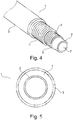
- FIG 4 shows the principles of an unbonded flexible pipe 1 which is used for transportation of fluid according to the invention.
- the unbonded flexible pipe 1 comprises an inner sealing sheath 2 and an outer polymer sheath 3.
- the inner sealing sheath 2 and the outer polymer sheath 3 define the annulus 4 in which the two armoring layers 5 and 6 are located.
- the inner sealing sheath 2 also defines a bore 7 in which the fluid is transported.
- the unbonded flexible pipe comprises two armoring layers 5 and 6, however, in other embodiments the unbonded flexible pipe may comprise other numbers of armoring layers, e.g. three or four armoring layers.
- a typical unbonded pipe comprises four armoring layers, i.e. two pressure amoring layers and two tensile armoring layers.
- the armoring layers are made of metal, such as duplex steel.
- the inner sealing sheath and the outer polymer sheath are made from a polymer material, such as polyethylene.
- the inner surface of the inner sealing sheath is not supported by a carcass, i.e. the inner sealing sheath is self-supporting.
- embodiments of unbonded flexible pipes comprising carcasses are also within the scope of the invention.
- Figure 5 is a section of an unbonded flexible pipe 1 showing the annulus 4 formed between the inner sealing sheath 2 and the outer polymer sheath 3.
- the annulus 4 comprises the armoring layers, however, even if the armoring layers fill must of the annulus, there will still be voids in the annulus which may be filled with gas originating from the fluid to be transported and which gas has permeated the inner sealing sheath.
- a corrosion promoting liquid is filled into the annulus and the liquid will fill the voids in the annulus and dissolve the gases present in the voids.
- the gases are H 2 S and CO 2 and the corrosion promoting liquid is sea water
- the gases will be dissolved in the sea water, and, thus, the gases will become less harmful in respect of corrosion.
- the sea water will still cause the stainless steel in the armoring layers to corrode, however, the progress of the corrosion will be so slow that the armoring layers will be able to maintain a sufficient strength during the service time of the unbonded flexible pipe.
- FIG 6 shows an alternative embodiment of an unbonded flexible pipe 1 suitable for use according to the invention.
- This pipe comprises an inner sealing sheath 2, an outer polymer sheath 3 forming an annulus there between, which annulus comprises the armoring layers 5 and 6 and further comprises two layers 8a and 8b of wick material.
- the wick material will absorb the corrosion promoting liquid, when it is filled into the annulus and transport the liquid through the annulus and ensure that voids will be filled with liquid and optional gases are dissolved in the liquid.
Landscapes
- Engineering & Computer Science (AREA)
- General Engineering & Computer Science (AREA)
- Mechanical Engineering (AREA)
- Mining & Mineral Resources (AREA)
- Life Sciences & Earth Sciences (AREA)
- Geology (AREA)
- Chemical & Material Sciences (AREA)
- Fluid Mechanics (AREA)
- Physics & Mathematics (AREA)
- Environmental & Geological Engineering (AREA)
- General Life Sciences & Earth Sciences (AREA)
- Geochemistry & Mineralogy (AREA)
- Metallurgy (AREA)
- Materials Engineering (AREA)
- Organic Chemistry (AREA)
- Rigid Pipes And Flexible Pipes (AREA)
- Earth Drilling (AREA)
- Preventing Corrosion Or Incrustation Of Metals (AREA)
Claims (13)
- Verfahren zum Installieren eines nichtverbundenen flexiblen Rohrs mit einer Bohrung zum Transport von Fluid, wobei das nichtverbundene flexible Rohr einen äußeren Mantel, einen inneren Dichtungsmantel im Inneren des äußeren Polymermantels, einen Ring zwischen dem äußeren Mantel und dem inneren Dichtungsmantel und mindestens eine metallische Bewehrungsschicht, welche Eisen umfasst, welche sich in dem Ring befindet, umfasst, wobei das Verfahren ein Befüllen mindestens eines Teils des Rings mit einer gleichmäßig verteilten korrosionsfördernden Flüssigkeit, die Wasser umfasst, vor oder nach einem Installieren des nichtverbundenen flexiblen Rohrs zwischen einer ersten Installation und einer zweiten Installation umfasst.
- Verfahren nach Anspruch 1, wobei die korrosionsfördernde Flüssigkeit in den Ring während einer Herstellung des nichtverbundenen flexiblen Rohrs gefüllt wird.
- Verfahren nach Anspruch 1, wobei das Verfahren ein Eintauchen des nichtverbundenen flexiblen Rohrs in Meerwasser und Verbinden davon mit der ersten und der zweiten Installation zum Transportieren von Fluid dazwischen umfasst, wobei mindestens eine der ersten und der zweiten Installation eine Unterwasserinstallation ist.
- Verfahren nach Anspruch 1, wobei die korrosionsfördernde Flüssigkeit gleichmäßig in dem Ring verteilt wird, wobei die korrosionsfördernde Flüssigkeit durch den Ring vorzugsweise zumindest teilweise mittels eines Dochtmaterials verteilt wird.
- Verfahren nach Anspruch 1, wobei mindestens 20 %, wie etwa mindestens 50 % und vorzugsweise mindestens 80 % des Rings mit der korrosionsfördernden Flüssigkeit befüllt wird.
- Verfahren nach Anspruch 1, wobei die korrosionsfördernde Flüssigkeit eine polare Flüssigkeit ist, wobei die korrosionsfördernde Flüssigkeit vorzugsweise Wasser umfasst.
- Verfahren nach Anspruch 1, wobei die korrosionsfördernde Flüssigkeit ein Fe-basiertes Salz umfasst.
- Verfahren nach Anspruch 1, wobei die korrosionsfördernde Flüssigkeit durch den Ring zumindest teilweise mittels eines Dochtmaterials verteilt wird.
- Verfahren nach Anspruch 1, wobei die korrosionsfördernde Flüssigkeit in den Ring über die erste und/oder die zweite Installation und/oder über Endanschlussstücke gefüllt wird.
- Verfahren nach Anspruch 1, wobei der Korrosionsgrad der Bewehrungsschichten in dem Ring gemessen wird.
- Unterwassersystem, umfassend ein nichtverbundenes flexibles Rohr und eine erste und eine zweite Installation, wobei mindestens eine der ersten und der zweiten Installation eine Unterwasserinstallation ist, wobei das nichtverbundene flexible Rohr eine Bohrung umfasst und angeordnet ist, um Fluid zwischen der ersten und der zweiten Installation zu transportieren, und wobei das nichtverbundene flexible Rohr einen äußeren Mantel, einen inneren Dichtungsmantel im Inneren des äußeren Polymermantels, einen Ring zwischen dem äußeren Mantel und dem inneren Dichtungsmantel und eine metallische Bewehrung, welche Eisen umfasst, welche sich in dem Ring befindet, umfasst, wobei der Ring zumindest teilweise mit einer gleichmäßig verteilten korrosionsfördernden Flüssigkeit befüllt wird, die Wasser umfasst.
- Unterwassersystem nach Anspruch 11, wobei die korrosionsfördernde Flüssigkeit Wasser, wie etwa Leitungswasser oder Meerwasser, ist, wobei die korrosionsfördernde Flüssigkeit vorzugsweise ein Fe-basiertes Salz umfasst.
- Unterwassersystem nach Anspruch 11, wobei der Ring ferner ein Dochtmaterial umfasst, wobei das Dochtmaterial vorzugsweise eine oder mehrere Schichten in dem Ring oder ein oder mehrere Bänder, welche sich in dem Ring in der Längserstreckung des nichtverbundenen flexiblen Rohrs erstrecken, bildet, wobei das Dochtmaterial vorzugsweise Eisenfasern umfasst.
Applications Claiming Priority (3)
| Application Number | Priority Date | Filing Date | Title |
|---|---|---|---|
| DKPA201470692 | 2014-11-13 | ||
| DKPA201570070 | 2015-02-06 | ||
| PCT/DK2015/050338 WO2016074681A1 (en) | 2014-11-13 | 2015-11-09 | A method of installing an unbonded flexible pipe |
Publications (3)
| Publication Number | Publication Date |
|---|---|
| EP3218629A1 EP3218629A1 (de) | 2017-09-20 |
| EP3218629A4 EP3218629A4 (de) | 2018-06-27 |
| EP3218629B1 true EP3218629B1 (de) | 2020-06-17 |
Family
ID=58731554
Family Applications (1)
| Application Number | Title | Priority Date | Filing Date |
|---|---|---|---|
| EP15858692.5A Active EP3218629B1 (de) | 2014-11-13 | 2015-11-09 | Verfahren zur installation eines unverbundenen flexiblen rohrs |
Country Status (4)
| Country | Link |
|---|---|
| US (1) | US10513896B2 (de) |
| EP (1) | EP3218629B1 (de) |
| AU (1) | AU2015345613B2 (de) |
| BR (1) | BR112017009974B8 (de) |
Cited By (1)
| Publication number | Priority date | Publication date | Assignee | Title |
|---|---|---|---|---|
| US11135454B2 (en) | 2015-06-24 | 2021-10-05 | The Regents Of The University Of Michigan | Histotripsy therapy systems and methods for the treatment of brain tissue |
Families Citing this family (24)
| Publication number | Priority date | Publication date | Assignee | Title |
|---|---|---|---|---|
| BRPI0914973B1 (pt) | 2008-06-09 | 2022-04-26 | Flexsteel Pipeline Technologies, Inc | Equipamento para fixação de tubo flexível a tubo flexível adicional em configuração de extremidade a extremidade |
| CN103988008A (zh) | 2011-10-04 | 2014-08-13 | 弗莱克斯蒂尔管道技术股份有限公司 | 具有改进的排出性的管道端部配件 |
| BR112017006628B1 (pt) | 2014-09-30 | 2021-09-08 | Flexsteel Pipeline Technologies, Inc | Conector de tubos e método de montagem de um conector de tubos |
| CA3004049C (en) | 2015-11-02 | 2021-06-01 | Flexsteel Pipeline Technologies, Inc. | Real time integrity monitoring of on-shore pipes |
| US10981765B2 (en) | 2016-06-28 | 2021-04-20 | Trinity Bay Equipment Holdings, LLC | Half-moon lifting device |
| GB201611246D0 (en) * | 2016-06-29 | 2016-08-10 | Ge Oil & Gas Uk Ltd | Gas venting |
| US11208257B2 (en) | 2016-06-29 | 2021-12-28 | Trinity Bay Equipment Holdings, LLC | Pipe coil skid with side rails and method of use |
| US11235946B2 (en) | 2016-10-10 | 2022-02-01 | Trinity Bay Equipment Holdings, LLC | Expandable drum assembly for deploying coiled pipe and method of using same |
| BR112019007181A2 (pt) | 2016-10-10 | 2019-07-02 | Trinity Bay Equipment Holdings, LLC | reboque de instalação para tubo flexível em bobina e método de utilização do mesmo |
| US10526164B2 (en) | 2017-08-21 | 2020-01-07 | Trinity Bay Equipment Holdings, LLC | System and method for a flexible pipe containment sled |
| BR112020008740A2 (pt) | 2017-11-01 | 2020-10-13 | Trinity Bay Equipment Holdings, LLC | sistema e método para manuseio de carretel de tubo |
| CN111902312B (zh) | 2018-02-01 | 2023-07-18 | 圣三一海湾设备控股有限公司 | 具有侧轨的管道卷垫块及使用方法 |
| CA3092070A1 (en) | 2018-02-22 | 2019-08-29 | Trinity Bay Equipment Holdings, LLC | System and method for deploying coils of spoolable pipe |
| CN113165825A (zh) | 2018-10-12 | 2021-07-23 | 圣三一海湾设备控股有限公司 | 用于盘绕的柔性管材的安装拖车及其使用方法 |
| AR118122A1 (es) | 2019-02-15 | 2021-09-22 | Trinity Bay Equipment Holdings Llc | Sistema de manejo de tubo flexible y método para usar el mismo |
| US10753512B1 (en) | 2019-03-28 | 2020-08-25 | Trinity Bay Equipment Holdings, LLC | System and method for securing fittings to flexible pipe |
| CN112682586B (zh) * | 2019-10-18 | 2024-08-27 | 泰克尼普法国公司 | 用于浸没在水域内的输送天然气和/或石油流体的柔性管 |
| US10926972B1 (en) | 2019-11-01 | 2021-02-23 | Trinity Bay Equipment Holdings, LLC | Mobile cradle frame for pipe reel |
| EP4058709B1 (de) | 2019-11-22 | 2025-05-07 | FlexSteel USA, LLC | Stauchrohrverbindungssysteme und verfahren |
| WO2021102318A1 (en) | 2019-11-22 | 2021-05-27 | Trinity Bay Equipment Holdings, LLC | Reusable pipe fitting systems and methods |
| AU2020386635A1 (en) | 2019-11-22 | 2022-06-09 | Trinity Bay Equipment Holdings, LLC | Potted pipe fitting systems and methods |
| US10822194B1 (en) | 2019-12-19 | 2020-11-03 | Trinity Bay Equipment Holdings, LLC | Expandable coil deployment system for drum assembly and method of using same |
| US10844976B1 (en) | 2020-02-17 | 2020-11-24 | Trinity Bay Equipment Holdings, LLC | Methods and apparatus for pulling flexible pipe |
| CN111721615B (zh) * | 2020-07-10 | 2023-04-07 | 中国石油天然气集团有限公司 | 一种油套环空污染环境中管材应力腐蚀开裂敏感性评价装置及方法 |
Family Cites Families (20)
| Publication number | Priority date | Publication date | Assignee | Title |
|---|---|---|---|---|
| WO1987001058A1 (fr) | 1985-08-16 | 1987-02-26 | Trest "Juzhvodoprovod" | Procede pour l'elimination des depots sur la surface interieure d'une canalisation et pour l'application sur celle-ci d'un revetement protecteur |
| DE19709373A1 (de) | 1997-03-07 | 1998-09-10 | Manfred Veenker | Leitung für gefährdende Fluide und Verfahren zu deren Herstellung |
| EP1119684B1 (de) | 1998-09-24 | 2003-05-07 | NKT Flexibles A/S | Verstärktes flexibles rohr mit leckflüssigkeitsrückführung |
| EP1255944B1 (de) * | 2000-01-14 | 2005-11-30 | NKT Flexibles I/S | Biegsames, armiertes rohr und dessen verwendung |
| FR2816691B1 (fr) | 2000-11-10 | 2002-12-27 | Coflexip | Dispositif de protection cathodique des conduites flexibles |
| FR2837870B1 (fr) | 2002-03-28 | 2005-01-28 | Coflexip | Procede et dispositif pour detecter des caracteriqtiques d'un fluide present dans un annulaire d'une colonne montante |
| US7082822B2 (en) * | 2002-04-05 | 2006-08-01 | Vetco Gray Inc. | Internal riser inspection device and methods of using same |
| FR2858841B1 (fr) | 2003-08-14 | 2007-02-09 | Technip France | Methode de drainage et d'evacuation des gaz de permeation d'une conduite tubulaire flexible et conduite adaptee a sa mise en oeuvre |
| US20060278397A1 (en) * | 2005-06-13 | 2006-12-14 | Mentor Subsea Technology Services, Inc. | Top tensioned riser adaptor |
| GB2446670C (en) | 2007-07-11 | 2013-03-13 | Flexlife Ltd | Inspection method |
| BRPI0907411A2 (pt) | 2008-01-25 | 2015-07-21 | Prad Res & Dev Ltd | Sistema de monitoramento de um tubo flexivel, método para monitorar a integridade de um tubo flexivel de uma instalação submarina, sistema de monitoramento de uma quantidade de água acumulada em um anel de um tubo flexivel, e método de monitoramento de uma quantidade de água acumulada em anel de um tubo |
| GB0821989D0 (en) * | 2008-12-02 | 2009-01-07 | Wellstream Int Ltd | Flexible pipe |
| WO2011026801A1 (en) * | 2009-09-01 | 2011-03-10 | Shell Internationale Research Maatschappij B.V. | Method of protecting a flexible pipe from corrosion and a flexible pipe |
| CA2783889A1 (en) * | 2009-12-16 | 2011-06-23 | National Oilwell Varco Denmark I/S | A flexible pipe |
| GB201013126D0 (en) | 2010-08-04 | 2010-09-22 | Flexlife Ltd | Corrosion protection |
| AU2012204952B2 (en) * | 2011-01-06 | 2016-11-03 | National Oilwell Varco Denmark I/S | An unbonded flexible pipe |
| US8820412B2 (en) | 2011-09-16 | 2014-09-02 | Chevron U.S.A. Inc. | Methods, systems and apparatus for circulating fluid within the annulus of a flexible pipe riser |
| DE102012207179A1 (de) | 2012-04-30 | 2013-10-31 | Evonik Industries Ag | Verschleißindikatorsystem für Offshore-Korrosionsschutz-Umhüllungssysteme |
| WO2014023311A1 (en) * | 2012-07-06 | 2014-02-13 | National Oilwell Varco Denmark I/S | An unbonded flexible pipe |
| US9500035B2 (en) * | 2014-10-06 | 2016-11-22 | Chevron U.S.A. Inc. | Integrated managed pressure drilling transient hydraulic model simulator architecture |
-
2015
- 2015-11-09 EP EP15858692.5A patent/EP3218629B1/de active Active
- 2015-11-09 BR BR112017009974A patent/BR112017009974B8/pt active IP Right Grant
- 2015-11-09 AU AU2015345613A patent/AU2015345613B2/en active Active
- 2015-11-09 US US15/525,782 patent/US10513896B2/en active Active
Non-Patent Citations (1)
| Title |
|---|
| None * |
Cited By (1)
| Publication number | Priority date | Publication date | Assignee | Title |
|---|---|---|---|---|
| US11135454B2 (en) | 2015-06-24 | 2021-10-05 | The Regents Of The University Of Michigan | Histotripsy therapy systems and methods for the treatment of brain tissue |
Also Published As
| Publication number | Publication date |
|---|---|
| EP3218629A4 (de) | 2018-06-27 |
| US20180298705A1 (en) | 2018-10-18 |
| BR112017009974A2 (pt) | 2018-02-14 |
| US10513896B2 (en) | 2019-12-24 |
| BR112017009974B8 (pt) | 2021-08-03 |
| AU2015345613B2 (en) | 2019-10-03 |
| BR112017009974B1 (pt) | 2021-07-27 |
| EP3218629A1 (de) | 2017-09-20 |
| AU2015345613A1 (en) | 2017-05-25 |
Similar Documents
| Publication | Publication Date | Title |
|---|---|---|
| EP3218629B1 (de) | Verfahren zur installation eines unverbundenen flexiblen rohrs | |
| WO2011026801A1 (en) | Method of protecting a flexible pipe from corrosion and a flexible pipe | |
| RU2341433C2 (ru) | Хранилище, расположенное на морском дне | |
| US9523446B2 (en) | Unbonded flexible pipe | |
| EP2356361B1 (de) | Entlüftungsventil | |
| US8702350B2 (en) | Riser assembly | |
| US20130068465A1 (en) | Methods and systems for circulating fluid within the annulus of a flexible pipe riser | |
| US9470365B1 (en) | Apparatus, methods, and systems for storing and managing liquids in an offshore environment | |
| OA11183A (en) | Method and apparatus for producing and shipping hydrocarbons offshore | |
| EP1912863B1 (de) | Einfache systeme zum transfer kryogener fluide | |
| US8235628B2 (en) | Continuously pressurized pipeline | |
| EP3105485B1 (de) | Bereitstellung von vorbestimmter flüssigkeit | |
| WO2016074681A1 (en) | A method of installing an unbonded flexible pipe | |
| AU2018277128B2 (en) | Pipe for control and forced circulation of corrosion-inhibiting fluids in the annulus thereof | |
| OA18545A (en) | A method of installing an unbonded flexible pipe | |
| AU735485B2 (en) | Method and apparatus for producing and shipping hydrocarbons offshore | |
| US20140305531A1 (en) | Flexible pipe | |
| WO2020099228A1 (en) | A method for flushing a flexible pipe and an assembly of a flexible pipe and an end-fitting | |
| US9260649B2 (en) | Method and system for reducing oxidation of glycol in fluid handling systems | |
| Bensimon et al. | Technology gaps and preferred architectures for deepwater FPSOs | |
| Colquhoun et al. | Wellstream Corporation, 800 Bering Drive, Houston, Texas | |
| GB2356183A (en) | Method and apparatus for producing and storing hydrocarbons offshore |
Legal Events
| Date | Code | Title | Description |
|---|---|---|---|
| STAA | Information on the status of an ep patent application or granted ep patent |
Free format text: STATUS: THE INTERNATIONAL PUBLICATION HAS BEEN MADE |
|
| PUAI | Public reference made under article 153(3) epc to a published international application that has entered the european phase |
Free format text: ORIGINAL CODE: 0009012 |
|
| STAA | Information on the status of an ep patent application or granted ep patent |
Free format text: STATUS: REQUEST FOR EXAMINATION WAS MADE |
|
| 17P | Request for examination filed |
Effective date: 20170508 |
|
| AK | Designated contracting states |
Kind code of ref document: A1 Designated state(s): AL AT BE BG CH CY CZ DE DK EE ES FI FR GB GR HR HU IE IS IT LI LT LU LV MC MK MT NL NO PL PT RO RS SE SI SK SM TR |
|
| AX | Request for extension of the european patent |
Extension state: BA ME |
|
| DAV | Request for validation of the european patent (deleted) | ||
| DAX | Request for extension of the european patent (deleted) | ||
| A4 | Supplementary search report drawn up and despatched |
Effective date: 20180530 |
|
| RIC1 | Information provided on ipc code assigned before grant |
Ipc: C23F 13/00 20060101ALI20180524BHEP Ipc: F16L 11/04 20060101ALI20180524BHEP Ipc: F16L 58/00 20060101ALI20180524BHEP Ipc: F16L 11/08 20060101AFI20180524BHEP |
|
| RIC1 | Information provided on ipc code assigned before grant |
Ipc: F16L 11/08 20060101AFI20191202BHEP Ipc: E21B 17/01 20060101ALI20191202BHEP Ipc: F16L 11/20 20060101ALI20191202BHEP Ipc: C23F 13/00 20060101ALI20191202BHEP Ipc: F16L 11/04 20060101ALI20191202BHEP Ipc: F16L 58/00 20060101ALI20191202BHEP |
|
| GRAP | Despatch of communication of intention to grant a patent |
Free format text: ORIGINAL CODE: EPIDOSNIGR1 |
|
| STAA | Information on the status of an ep patent application or granted ep patent |
Free format text: STATUS: GRANT OF PATENT IS INTENDED |
|
| INTG | Intention to grant announced |
Effective date: 20200117 |
|
| GRAS | Grant fee paid |
Free format text: ORIGINAL CODE: EPIDOSNIGR3 |
|
| GRAA | (expected) grant |
Free format text: ORIGINAL CODE: 0009210 |
|
| STAA | Information on the status of an ep patent application or granted ep patent |
Free format text: STATUS: THE PATENT HAS BEEN GRANTED |
|
| AK | Designated contracting states |
Kind code of ref document: B1 Designated state(s): AL AT BE BG CH CY CZ DE DK EE ES FI FR GB GR HR HU IE IS IT LI LT LU LV MC MK MT NL NO PL PT RO RS SE SI SK SM TR |
|
| REG | Reference to a national code |
Ref country code: GB Ref legal event code: FG4D |
|
| REG | Reference to a national code |
Ref country code: CH Ref legal event code: EP |
|
| REG | Reference to a national code |
Ref country code: IE Ref legal event code: FG4D |
|
| REG | Reference to a national code |
Ref country code: DE Ref legal event code: R096 Ref document number: 602015054530 Country of ref document: DE |
|
| REG | Reference to a national code |
Ref country code: AT Ref legal event code: REF Ref document number: 1281724 Country of ref document: AT Kind code of ref document: T Effective date: 20200715 |
|
| REG | Reference to a national code |
Ref country code: NO Ref legal event code: T2 Effective date: 20200617 |
|
| PG25 | Lapsed in a contracting state [announced via postgrant information from national office to epo] |
Ref country code: FI Free format text: LAPSE BECAUSE OF FAILURE TO SUBMIT A TRANSLATION OF THE DESCRIPTION OR TO PAY THE FEE WITHIN THE PRESCRIBED TIME-LIMIT Effective date: 20200617 Ref country code: LT Free format text: LAPSE BECAUSE OF FAILURE TO SUBMIT A TRANSLATION OF THE DESCRIPTION OR TO PAY THE FEE WITHIN THE PRESCRIBED TIME-LIMIT Effective date: 20200617 Ref country code: SE Free format text: LAPSE BECAUSE OF FAILURE TO SUBMIT A TRANSLATION OF THE DESCRIPTION OR TO PAY THE FEE WITHIN THE PRESCRIBED TIME-LIMIT Effective date: 20200617 Ref country code: GR Free format text: LAPSE BECAUSE OF FAILURE TO SUBMIT A TRANSLATION OF THE DESCRIPTION OR TO PAY THE FEE WITHIN THE PRESCRIBED TIME-LIMIT Effective date: 20200918 |
|
| REG | Reference to a national code |
Ref country code: LT Ref legal event code: MG4D |
|
| REG | Reference to a national code |
Ref country code: NL Ref legal event code: MP Effective date: 20200617 |
|
| PG25 | Lapsed in a contracting state [announced via postgrant information from national office to epo] |
Ref country code: RS Free format text: LAPSE BECAUSE OF FAILURE TO SUBMIT A TRANSLATION OF THE DESCRIPTION OR TO PAY THE FEE WITHIN THE PRESCRIBED TIME-LIMIT Effective date: 20200617 Ref country code: BG Free format text: LAPSE BECAUSE OF FAILURE TO SUBMIT A TRANSLATION OF THE DESCRIPTION OR TO PAY THE FEE WITHIN THE PRESCRIBED TIME-LIMIT Effective date: 20200917 Ref country code: LV Free format text: LAPSE BECAUSE OF FAILURE TO SUBMIT A TRANSLATION OF THE DESCRIPTION OR TO PAY THE FEE WITHIN THE PRESCRIBED TIME-LIMIT Effective date: 20200617 Ref country code: HR Free format text: LAPSE BECAUSE OF FAILURE TO SUBMIT A TRANSLATION OF THE DESCRIPTION OR TO PAY THE FEE WITHIN THE PRESCRIBED TIME-LIMIT Effective date: 20200617 |
|
| REG | Reference to a national code |
Ref country code: AT Ref legal event code: MK05 Ref document number: 1281724 Country of ref document: AT Kind code of ref document: T Effective date: 20200617 |
|
| PG25 | Lapsed in a contracting state [announced via postgrant information from national office to epo] |
Ref country code: NL Free format text: LAPSE BECAUSE OF FAILURE TO SUBMIT A TRANSLATION OF THE DESCRIPTION OR TO PAY THE FEE WITHIN THE PRESCRIBED TIME-LIMIT Effective date: 20200617 Ref country code: AL Free format text: LAPSE BECAUSE OF FAILURE TO SUBMIT A TRANSLATION OF THE DESCRIPTION OR TO PAY THE FEE WITHIN THE PRESCRIBED TIME-LIMIT Effective date: 20200617 |
|
| PG25 | Lapsed in a contracting state [announced via postgrant information from national office to epo] |
Ref country code: SM Free format text: LAPSE BECAUSE OF FAILURE TO SUBMIT A TRANSLATION OF THE DESCRIPTION OR TO PAY THE FEE WITHIN THE PRESCRIBED TIME-LIMIT Effective date: 20200617 Ref country code: IT Free format text: LAPSE BECAUSE OF FAILURE TO SUBMIT A TRANSLATION OF THE DESCRIPTION OR TO PAY THE FEE WITHIN THE PRESCRIBED TIME-LIMIT Effective date: 20200617 Ref country code: AT Free format text: LAPSE BECAUSE OF FAILURE TO SUBMIT A TRANSLATION OF THE DESCRIPTION OR TO PAY THE FEE WITHIN THE PRESCRIBED TIME-LIMIT Effective date: 20200617 Ref country code: CZ Free format text: LAPSE BECAUSE OF FAILURE TO SUBMIT A TRANSLATION OF THE DESCRIPTION OR TO PAY THE FEE WITHIN THE PRESCRIBED TIME-LIMIT Effective date: 20200617 Ref country code: EE Free format text: LAPSE BECAUSE OF FAILURE TO SUBMIT A TRANSLATION OF THE DESCRIPTION OR TO PAY THE FEE WITHIN THE PRESCRIBED TIME-LIMIT Effective date: 20200617 Ref country code: RO Free format text: LAPSE BECAUSE OF FAILURE TO SUBMIT A TRANSLATION OF THE DESCRIPTION OR TO PAY THE FEE WITHIN THE PRESCRIBED TIME-LIMIT Effective date: 20200617 Ref country code: ES Free format text: LAPSE BECAUSE OF FAILURE TO SUBMIT A TRANSLATION OF THE DESCRIPTION OR TO PAY THE FEE WITHIN THE PRESCRIBED TIME-LIMIT Effective date: 20200617 Ref country code: PT Free format text: LAPSE BECAUSE OF FAILURE TO SUBMIT A TRANSLATION OF THE DESCRIPTION OR TO PAY THE FEE WITHIN THE PRESCRIBED TIME-LIMIT Effective date: 20201019 |
|
| PGFP | Annual fee paid to national office [announced via postgrant information from national office to epo] |
Ref country code: FR Payment date: 20201013 Year of fee payment: 6 |
|
| PG25 | Lapsed in a contracting state [announced via postgrant information from national office to epo] |
Ref country code: PL Free format text: LAPSE BECAUSE OF FAILURE TO SUBMIT A TRANSLATION OF THE DESCRIPTION OR TO PAY THE FEE WITHIN THE PRESCRIBED TIME-LIMIT Effective date: 20200617 Ref country code: SK Free format text: LAPSE BECAUSE OF FAILURE TO SUBMIT A TRANSLATION OF THE DESCRIPTION OR TO PAY THE FEE WITHIN THE PRESCRIBED TIME-LIMIT Effective date: 20200617 Ref country code: IS Free format text: LAPSE BECAUSE OF FAILURE TO SUBMIT A TRANSLATION OF THE DESCRIPTION OR TO PAY THE FEE WITHIN THE PRESCRIBED TIME-LIMIT Effective date: 20201017 |
|
| REG | Reference to a national code |
Ref country code: DE Ref legal event code: R097 Ref document number: 602015054530 Country of ref document: DE |
|
| PLBE | No opposition filed within time limit |
Free format text: ORIGINAL CODE: 0009261 |
|
| STAA | Information on the status of an ep patent application or granted ep patent |
Free format text: STATUS: NO OPPOSITION FILED WITHIN TIME LIMIT |
|
| PG25 | Lapsed in a contracting state [announced via postgrant information from national office to epo] |
Ref country code: DK Free format text: LAPSE BECAUSE OF FAILURE TO SUBMIT A TRANSLATION OF THE DESCRIPTION OR TO PAY THE FEE WITHIN THE PRESCRIBED TIME-LIMIT Effective date: 20200617 |
|
| 26N | No opposition filed |
Effective date: 20210318 |
|
| PG25 | Lapsed in a contracting state [announced via postgrant information from national office to epo] |
Ref country code: SI Free format text: LAPSE BECAUSE OF FAILURE TO SUBMIT A TRANSLATION OF THE DESCRIPTION OR TO PAY THE FEE WITHIN THE PRESCRIBED TIME-LIMIT Effective date: 20200617 |
|
| REG | Reference to a national code |
Ref country code: DE Ref legal event code: R119 Ref document number: 602015054530 Country of ref document: DE |
|
| PG25 | Lapsed in a contracting state [announced via postgrant information from national office to epo] |
Ref country code: MC Free format text: LAPSE BECAUSE OF FAILURE TO SUBMIT A TRANSLATION OF THE DESCRIPTION OR TO PAY THE FEE WITHIN THE PRESCRIBED TIME-LIMIT Effective date: 20200617 |
|
| REG | Reference to a national code |
Ref country code: CH Ref legal event code: PL |
|
| PG25 | Lapsed in a contracting state [announced via postgrant information from national office to epo] |
Ref country code: LU Free format text: LAPSE BECAUSE OF NON-PAYMENT OF DUE FEES Effective date: 20201109 |
|
| REG | Reference to a national code |
Ref country code: BE Ref legal event code: MM Effective date: 20201130 |
|
| PG25 | Lapsed in a contracting state [announced via postgrant information from national office to epo] |
Ref country code: LI Free format text: LAPSE BECAUSE OF NON-PAYMENT OF DUE FEES Effective date: 20201130 Ref country code: CH Free format text: LAPSE BECAUSE OF NON-PAYMENT OF DUE FEES Effective date: 20201130 |
|
| PG25 | Lapsed in a contracting state [announced via postgrant information from national office to epo] |
Ref country code: IE Free format text: LAPSE BECAUSE OF NON-PAYMENT OF DUE FEES Effective date: 20201109 |
|
| PG25 | Lapsed in a contracting state [announced via postgrant information from national office to epo] |
Ref country code: DE Free format text: LAPSE BECAUSE OF NON-PAYMENT OF DUE FEES Effective date: 20210601 |
|
| PG25 | Lapsed in a contracting state [announced via postgrant information from national office to epo] |
Ref country code: TR Free format text: LAPSE BECAUSE OF FAILURE TO SUBMIT A TRANSLATION OF THE DESCRIPTION OR TO PAY THE FEE WITHIN THE PRESCRIBED TIME-LIMIT Effective date: 20200617 Ref country code: MT Free format text: LAPSE BECAUSE OF FAILURE TO SUBMIT A TRANSLATION OF THE DESCRIPTION OR TO PAY THE FEE WITHIN THE PRESCRIBED TIME-LIMIT Effective date: 20200617 Ref country code: CY Free format text: LAPSE BECAUSE OF FAILURE TO SUBMIT A TRANSLATION OF THE DESCRIPTION OR TO PAY THE FEE WITHIN THE PRESCRIBED TIME-LIMIT Effective date: 20200617 |
|
| PG25 | Lapsed in a contracting state [announced via postgrant information from national office to epo] |
Ref country code: MK Free format text: LAPSE BECAUSE OF FAILURE TO SUBMIT A TRANSLATION OF THE DESCRIPTION OR TO PAY THE FEE WITHIN THE PRESCRIBED TIME-LIMIT Effective date: 20200617 |
|
| PG25 | Lapsed in a contracting state [announced via postgrant information from national office to epo] |
Ref country code: BE Free format text: LAPSE BECAUSE OF NON-PAYMENT OF DUE FEES Effective date: 20201130 |
|
| PG25 | Lapsed in a contracting state [announced via postgrant information from national office to epo] |
Ref country code: FR Free format text: LAPSE BECAUSE OF NON-PAYMENT OF DUE FEES Effective date: 20211130 |
|
| P01 | Opt-out of the competence of the unified patent court (upc) registered |
Effective date: 20230501 |
|
| PGFP | Annual fee paid to national office [announced via postgrant information from national office to epo] |
Ref country code: GB Payment date: 20250918 Year of fee payment: 11 |
|
| PGFP | Annual fee paid to national office [announced via postgrant information from national office to epo] |
Ref country code: NO Payment date: 20251113 Year of fee payment: 11 |