EP3218969B1 - Filtre de ligne et procédé d'installation d'un filtre de ligne sur un câble de système - Google Patents
Filtre de ligne et procédé d'installation d'un filtre de ligne sur un câble de système Download PDFInfo
- Publication number
- EP3218969B1 EP3218969B1 EP15793729.3A EP15793729A EP3218969B1 EP 3218969 B1 EP3218969 B1 EP 3218969B1 EP 15793729 A EP15793729 A EP 15793729A EP 3218969 B1 EP3218969 B1 EP 3218969B1
- Authority
- EP
- European Patent Office
- Prior art keywords
- line filter
- system cable
- cable
- path
- shunt
- Prior art date
- Legal status (The legal status is an assumption and is not a legal conclusion. Google has not performed a legal analysis and makes no representation as to the accuracy of the status listed.)
- Active
Links
Images


Classifications
-
- H—ELECTRICITY
- H03—ELECTRONIC CIRCUITRY
- H03H—IMPEDANCE NETWORKS, e.g. RESONANT CIRCUITS; RESONATORS
- H03H1/00—Constructional details of impedance networks whose electrical mode of operation is not specified or applicable to more than one type of network
- H03H1/0007—Constructional details of impedance networks whose electrical mode of operation is not specified or applicable to more than one type of network of radio frequency interference filters
-
- H—ELECTRICITY
- H01—ELECTRIC ELEMENTS
- H01R—ELECTRICALLY-CONDUCTIVE CONNECTIONS; STRUCTURAL ASSOCIATIONS OF A PLURALITY OF MUTUALLY-INSULATED ELECTRICAL CONNECTING ELEMENTS; COUPLING DEVICES; CURRENT COLLECTORS
- H01R4/00—Electrically-conductive connections between two or more conductive members in direct contact, i.e. touching one another; Means for effecting or maintaining such contact; Electrically-conductive connections having two or more spaced connecting locations for conductors and using contact members penetrating insulation
- H01R4/24—Connections using contact members penetrating or cutting insulation or cable strands
- H01R4/2404—Connections using contact members penetrating or cutting insulation or cable strands the contact members having teeth, prongs, pins or needles penetrating the insulation
- H01R4/2408—Connections using contact members penetrating or cutting insulation or cable strands the contact members having teeth, prongs, pins or needles penetrating the insulation actuated by clamping screws
-
- H—ELECTRICITY
- H01—ELECTRIC ELEMENTS
- H01F—MAGNETS; INDUCTANCES; TRANSFORMERS; SELECTION OF MATERIALS FOR THEIR MAGNETIC PROPERTIES
- H01F27/00—Details of transformers or inductances, in general
- H01F27/28—Coils; Windings; Conductive connections
-
- H—ELECTRICITY
- H01—ELECTRIC ELEMENTS
- H01R—ELECTRICALLY-CONDUCTIVE CONNECTIONS; STRUCTURAL ASSOCIATIONS OF A PLURALITY OF MUTUALLY-INSULATED ELECTRICAL CONNECTING ELEMENTS; COUPLING DEVICES; CURRENT COLLECTORS
- H01R9/00—Structural associations of a plurality of mutually-insulated electrical connecting elements, e.g. terminal strips or terminal blocks; Terminals or binding posts mounted upon a base or in a case; Bases therefor
- H01R9/03—Connectors arranged to contact a plurality of the conductors of a multiconductor cable, e.g. tapping connections
- H01R9/031—Connectors arranged to contact a plurality of the conductors of a multiconductor cable, e.g. tapping connections for multiphase cables, e.g. with contact members penetrating insulation of a plurality of conductors
-
- H—ELECTRICITY
- H02—GENERATION; CONVERSION OR DISTRIBUTION OF ELECTRIC POWER
- H02M—APPARATUS FOR CONVERSION BETWEEN AC AND AC, BETWEEN AC AND DC, OR BETWEEN DC AND DC, AND FOR USE WITH MAINS OR SIMILAR POWER SUPPLY SYSTEMS; CONVERSION OF DC OR AC INPUT POWER INTO SURGE OUTPUT POWER; CONTROL OR REGULATION THEREOF
- H02M1/00—Details of apparatus for conversion
- H02M1/12—Arrangements for reducing harmonics from AC input or output
- H02M1/126—Arrangements for reducing harmonics from AC input or output using passive filters
-
- H—ELECTRICITY
- H01—ELECTRIC ELEMENTS
- H01R—ELECTRICALLY-CONDUCTIVE CONNECTIONS; STRUCTURAL ASSOCIATIONS OF A PLURALITY OF MUTUALLY-INSULATED ELECTRICAL CONNECTING ELEMENTS; COUPLING DEVICES; CURRENT COLLECTORS
- H01R13/00—Details of coupling devices of the kinds covered by groups H01R12/70 or H01R24/00 - H01R33/00
- H01R13/66—Structural association with built-in electrical component
- H01R13/719—Structural association with built-in electrical component specially adapted for high frequency, e.g. with filters
-
- H—ELECTRICITY
- H03—ELECTRONIC CIRCUITRY
- H03H—IMPEDANCE NETWORKS, e.g. RESONANT CIRCUITS; RESONATORS
- H03H1/00—Constructional details of impedance networks whose electrical mode of operation is not specified or applicable to more than one type of network
- H03H2001/0092—Inductor filters, i.e. inductors whose parasitic capacitance is of relevance to consider it as filter
Definitions
- a line filter is a kind of electronic filter that is placed between an electronic device and an external line, or placed in any line interconnecting electronic devices within a system.
- a line filter is usually used to attenuate conducted radio frequencies (RFI), also known as electromagnetic interference (EMI) between the external line and the electronic device, or between electronic devices within a system.
- RFID conducted radio frequencies
- EMI electromagnetic interference
- the line filters comprise a field wiring power terminal at the line side and another field wiring power terminal at the load side.
- the terminals are configured to be connected with a system cable input and a system cable output. In a three-wire-system, for example, this requires six system cable terminations each capable of carrying the full system current. For each termination the system cable must be prepared with the correct length of insulation removal, the wire end finished with a suitable sleeve and the cable fastened to the terminal with the correct torque. Periodically this torque must be re-checked.
- WO 2009/046762 A1 discloses an EMC active filter capable to maintain a low earth leakage current at all times, thus being compatible with RCD devices.
- the filter of the invention has an especially simple inductor's structure, where typically the power conductors pass straight through the filter, without windings, and most of the components can be implemented in a modular shunt circuit.
- the filter is realized by connecting the shunt module by an IDC device to the phase conductors, or directly to the line and load terminal, thus avoiding cutting and splicing high-current cables.
- the particular protection circuit of the filter prevents in-rush current at power on, and limits earth leakage current even in case of a fault in the line.
- the object is solved by the line filter according to claim 1.
- the further object is solved by the method according to the second independent claim.
- a line filter is provided which is configured to be installed onto a system cable, wherein the line filter comprises a magnetic component, the line filter defines a cable path through the line filter, the line filter is configured to allow placement of the system cable along the cable path at the time of an installation, thereby providing a magnetic coupling of the system cable to the magnetic component, and wherein the line filter comprises an insulation displacement connector and a shunt component wherein the insulation displacement connector is configured to be tightened at the time of the installation, thereby providing a galvanic connection of the system cable to the shunt component.
- the term "at the time of an installation” may refer to the installation of the line filter to a system cable of an external electronic device.
- the time of the installation is not a time during the manufacturing of the line filter.
- the system cable is not an intrinsic part of the line filter.
- the line filter is installed onto the system cable at a point in time after the manufacturing of the line filter, and by a person different from the manufacturer, in particular e.g. by an installer or user of the electronic device.
- the line filter may be a low pass filter.
- the line filter may be configured to attenuate radio frequency interference, also known as electromagnetic interference (EMI).
- EMI electromagnetic interference
- the line filter may be configured to attenuate a leakage current.
- the line filter may be configured to be connected between a power grid and an electrical load device or between electrical devices within a system, i.e. between a motor drive and motor.
- the line filter may provide electromagnetic compatibility (EMC) between devices.
- EMC electromagnetic compatibility
- the line filter may comprise a means for eliminating earth leakage current from the system cable in the frequency range 150 Hz to 150 kHz.
- the line may comprise series inductive and shunt capacitive components in a ladder network to provide attenuation of radio frequency interference in the frequency range 150 kHz to 30 MHz.
- the magnetic component is an inductor core.
- the cable path may be a predefined path which extends through the line filter.
- the cable path may connect a line side of the line filter to a load side of the line filter.
- placement of the system cable along the cable path may be understood as an operation carried out by a user of the line filter or by an installer of the line filter.
- the system cable may be placed manually along the cable path.
- the system cable may be placed along the cable path by pushing the system cable through the line filter.
- alternative embodiments for the placement the cable along the cable path are also possible.
- the insulation displacement connector is configured to provide a galvanic connection of the system cable to the shunt component.
- the IDC is configured to provide a voltage tap into the system cable which allows a small shunt current to be drawn from the system cable to the shunt component. Thereby, the same voltage may apply in the system cable and at the shunt component.
- the shunt component may comprise one or more shunt capacitors.
- the shunt component may be connected between the system cable and a grounding terminal, or between phases of the system cables.
- the line filter may comprise multiple shunt components which are connected in a ladder topology.
- the line filter is configured to be magnetically coupled and galvanically connected to the system cable at the time of an installation onto the system cable
- the line filter is free from an internal main power conductor connecting a line terminal and a load terminal.
- the system cable which is placed along the cable path at the time of installation directly connects with the magnetic components and the IDC.
- the provision of field wiring terminals on the line filter is completely unnecessary and this results in saving on their inherent cost and bulk.
- This facilitates the field wiring for installation of the line filter and the time-consuming preparation of the system cabling for termination. Accordingly, the operation of installing the line filter onto a system cable is significantly facilitated.
- the line filter comprises an aperture which is configured to allow placement of the system cable along the cable path by pushing the system cable through the aperture at the time of installation. Pushing the system cable through an aperture to enter into the line filter and providing another aperture through which the system cable can exit the line filter is a particularly easy way of installing the line filter onto the system cable. This allows a very fast installation and improves the user safety as installation errors, such as poor high current connections, are prevented.
- the IDC may comprise a screw and at least one conductive pin which is configured to pierce into the system cable when the screw is tightened.
- the IDC may comprise exactly one conductive pin.
- the IDC may comprise multiple conductive pins.
- the conductive pin may be configured to displace the insulation of the system cable. Accordingly, it is possible to de-install the line filter from the system cable by untightening the screw wherein the pin can be withdrawn from the system cable and the insulation sustains only minor damage.
- the pin may either be arranged to the end of the screw which is configured to face towards the system cable or the pin may be arranged such that it is on the side of the system cable which is opposite to the screw when the line filter installed onto the system cable.
- the conductive pin may be configured to pierce the system cable insulation and to protrude into the system cable a depth in the range of a fraction of a millimetre to several millimetres. In particular, the depth may be in the range of 0.01 mm to 20 mm.
- the system cable may comprise an inner conductor which is covered by an insulation. The conductive pin may be configured to pierce through the insulation and enter into the inner conductor.
- the depth by which the pin is designed to enter into the system cable can be adjusted to provide different conductivity characteristics for the galvanic connection of the IDC.
- the magnetic component is ring-shaped and comprises an opening.
- the cable path may pass through the opening of the magnetic component.
- the magnetic component may be configured to reinforce a magnetic flux which is created by a current flowing through the system cable passing through the opening of the magnetic component. Thereby, the magnetic coupling between said two elements may be increased.
- the line filter may be free from an internal conductor winding. Accordingly, the cable may follow a direct path through the line filter.
- the cable path may be configured such that the system cable may be guided through the line filter in an almost straight line. This facilitates the placement of the system cable along the cable path by pushing. In particular, minimal deformation or twists of the system cable may be required while pushing the system cable along the straight line.
- the IDC may be configured to draw a shunt current from the system cable through the galvanic connection of the system cable to the shunt component wherein the shunt current is lower than a power current flowing through the system cable.
- the shunt current may be orders of magnitude lower than a current flowing through the system cable.
- the line filter shunt components may be designed to draw a relatively low current compared with a power current flowing through the system cable. Accordingly, the power current can be very high and will sustain no attenuation whereas radio frequency interference shunt current is removed from the system cable.
- the shunt current may in the range of 0.1 A to 10 A.
- the current flowing through the system cable may be up to 1000 A.
- the current in the system cable may be in the range of 10 A to 1000 A.
- a voltage of up to 600 V may be present in the system cable.
- the line filter may be designed to provide attenuation in the frequency range 1 kHz to 30 MHz.
- the line filter may comprise multiple IDCs wherein each of the IDCs is configured to be tightened at the time of the installation, thereby providing galvanic connections of the system cable to the shunt component.
- the line filter may be configured to be installed onto a system cable which comprises one or more phases.
- the line filter may be configured such that all phases of the system cable are magnetically coupled to the same magnetic component when the system cable is placed along the cable path, or individual phases may couple to separate magnetic components.
- the line filter may be configured to galvanically connect each phase of the system cable to at least one insulation displacement connector. This design allows to galvanically connect the different phases of the system cable individually.
- the respective IDCs may be designed differently.
- the line filter may comprise multiple IDCs which are configured to be connected to the same phase of the system cable. This may allow drawing stronger shunt current, or may allow the connection of multiple stages of shunt component.
- the line filter further comprises a guiding element which is configured to mechanically guide the system cable along the cable path during the placement of the system cable along the cable path and which is configured to hold the system cable in the cable path once the system cable is placed along the cable path.
- the guiding element may be a plastic component.
- the line filter may be a low pass filter.
- the IDC may be configured to be connected to the system cable in a gas-tight connection.
- the IDC may be configured to provide a strain-relief when connected to the system cable.
- the IDC may be configured to provide a spring action which will maintain a constant clamping force over time.
- the line filter may be configured to be deinstalled from the system cable.
- the line filter may be deinstalled from the system cable by opening the IDC and by removing the system cable from the cable path, e.g. by pulling the system cable out of the line filter.
- the line filter may be configured such that during the deinstallation from the system cable, the system cable sustains minimal damage where the insulation is pierced but remains intact. The de-installation can be carried out by qualified user or installer.
- the line filter may comprise a housing wherein the insulation displacement connector is configured to pierce into the system cable at a position which is arranged inside the housing. Accordingly, the spot at which the system cable is pierce by the insulation displacement connector may be protected by the housing.
- the cable path extends through the housing.
- the magnetic component may be arranged inside the housing.
- the insulation displacement connector is arranged inside the housing.
- the insulation displacement connector is arranged completely inside the housing.
- the shunt component may be arranged inside the housing.
- the present invention relates to an assembly comprising the above-described line filter and the system cable.
- the present invention relates to a method of installing a line filter onto a system cable, wherein the line filter comprises a magnetic component, an IDC and a shunt component.
- the method comprises the steps of:
- the line filter used in the method may be identical to the above-described line filter such that every functional and structural feature disclosed with respect to the line filter may also be applied with respect to the method.
- Figure 1 shows a cross-sectional view of a line filter 1 which is installed onto a system cable 2.
- Figure 2 shows a perspective view of the line filter 1 installed onto the system cable 2.
- the line filter 1 is a kind of electronic filter that is placed between an electronic device (not shown) and a line (not shown) external to it, to attenuate conducted radio frequencies (RFI), also known as electromagnetic interference (EMI) between the external line and the electronic device or between electronic devices within a system.
- RFID conducted radio frequencies
- EMI electromagnetic interference
- the line filter 1 is provided by its manufacturer without the system cable 2. At the time of installation a suitable system cable 2 is provided by an installer. Then, the line filter 1 is installed onto the system cable 2 by an installer when the line filter 1 is placed between the electronic device and the line external to it or between electronic devices within a system.
- the system cable 2 comprises an insulation which covers a conductive internal material, e.g. copper.
- the line filter 1 comprises a housing 3. The housing 3 consists on a plastic material. The further parts of the line filter 1 are arranged inside the housing 3. The housing 3 is mountable on a system cabinet (not shown).
- the line filter 1 is a low pass filter.
- the line filter 1 comprises magnetic components 4 configured as in-line inductors and shunt components 5, e.g. shunt capacitors.
- the line filter 1 is configured such that the magnetic components 4 and the shunt components 5 form a LC-low pass filter when connected to the system cable 2.
- the line filter 1 defines a cable path 6 which runs through the line filter 1.
- the cable path 6 enters into the line filter 1 on a load side 7 and exits the line filter 1 on the line side 8.
- the line filter 1 is free from an internal main cable to which the system cable 2 would otherwise have to be electronically connected, e.g. by field wiring terminal.
- the line filter 1 comprises an aperture 9a at the load side 7 which is configured to allow entering the system cable 2 into the line filter 1 through the aperture 9a at the load side 7. Further, the line filter 1 comprises an aperture 10 at the line side 8 which is configured to allow exiting the system cable 2 from the line filter 1 through the aperture 10 at the line side 8.
- the system cable 2 comprises three phases 11, 12, 13.
- the line filter 1 comprises three apertures 9a, 9b, 9c arranged at the load side of the line filter.
- the line filter 1 comprises only one aperture 10 arranged at the line side 8 of the line filter 1.
- the cable path 6 defined through the line filter 1 connects each of the three apertures 9a, 9b, 9c on the load side 7 with the one aperture 10 on the line side 8.
- One phase 11, 12, 13 of the system cable 2 is entered into each of the apertures 9a, 9b, 9c on the load side 7 of the line filter 1. Further, all of the phases 9a, 9b, 9c of the system cable 2 exit the line filter 1 through the one aperture 10 on the line side 8.
- the line filter 1 comprises a guiding element 14 which is configured to help guide the system cable 2 along the cable path 6 during the placement of the system cable 2 along the cable path 6.
- the guiding element 14 is shaped as a single flat tube wherein multiple phases 11, 12, 13 of the system cable 2 are guided in the same flat tube.
- the guiding element 14 comprises a plastic material.
- the system cable 2 is placed along the cable path 6 by being pushed into the line filter 1 from the load side 7.
- the guiding element 14 is configured such that the system cable 2 slides along the guiding element 14 and is, thereby, guided along the cable path 6 through the line filter 1. Once the line filter 1 has been installed onto the system cable 2, the guiding element 14 holds the system cable 2 in its position along the cable path 6.
- the line filter 1 comprises two magnetic components 4. In alternative designs, the line filter 1 can comprise one or more magnetic components.
- Each of the magnetic components 4 is a ring-shaped inductor core.
- the magnetic components 4 are inductors which are configured to be in-line connected to the system cable by a magnetic coupling.
- Each of the magnetic components 4 defines an opening 15 wherein the cable path 6 passes through the openings 15.
- the system cable 2 runs through the openings 15 of the magnetic components 4.
- all phases 11, 12, 13 of the system cable 2 run through the same openings 15 in the magnetic components 4.
- the magnetic components 4 may be of any suitable shape which provides an opening 15.
- the phases 11, 12, 13 of system cable 2 may pass through separate magnetic components 4, i.e. one phase cable 11, 12, 13 per magnetic component 4.
- the line filter 1 further comprises at least one shunt component 5, e.g. a shunt capacitor.
- the line filter 1 further comprises an insulation displacement connector (IDC) 16.
- the IDC 16 is arranged in the vicinity of the load side 7 of the line filter 1.
- the IDC 16 comprises a screw 17 and a conductive pin 18.
- the conductive pin 18 is arranged at the end of the screw 17 which faces towards the system cable 2.
- the screw 17 and the pin 18 are formed by a single element.
- the screw 17 is a metal screw.
- the IDC 16 can be placed in any suitable location within the line filter 1.
- a platform 19 is arranged close to the end of the screw 17 which faces the system cable 2.
- the IDC 16 further comprises a cage 20.
- the platform 19 is configured to compress the system cable 2.
- the system cable 2 is mechanically fixed, e.g. clamped between the platform 19 and the cage 20, when the screw 17 is tightened.
- the cage 20 consists of a metal block 23 with thread to accept the screw 17 and a metal strap 24 that passes around the system cable 2.
- the conductive pin 18 pierces through the insulation of the system cable 2, thereby establishing a galvanic connection to the system cable 2.
- the insulation of the system cable is displaced when the conductive pin 18 pierces into the system cable 2.
- the pin 18 is pressed into the conductor of system cable 2 to provide a good galvanic connection to the conductive internal material of the system cable 2.
- the IDC 16 comprises a low current connection point (not shown) which is galvanically connected to the shunt components 5.
- the IDC 16 provides a galvanic connection of the system cable 2 to the shunt components 5.
- the IDC 16 comprises a small solder or crimp lug (not shown) configured to make a wire connection to at least one shunt component 5.
- the IDC 16 is configured to provide a voltage tap into the system cable 2. Accordingly, the same voltage as in the system cable 2 is also applied to the shunt component 5 when the galvanic connection is established. Further, the galvanic connection is configured to only draw a small shunt current through the conductive pin 18 from the system cable 2.
- the shunt current may be an order of magnitude, or more, smaller than the power current flowing through the system cable 2.
- the shunt current may be in the range of 0.1 A to 10 A.
- the IDC 16 comprises a plastic housing 21 which provides an insulation of the IDC 16.
- the IDC 16 is configured to provide a gas-tight seal of the system cable 2.
- the gas-tight seal is formed by the pressure of the platform 19 and cage 20 on the insulation of the system cable 2 and by the pressure applied by the displaced insulation of the system cable 2 on the conductive pin 18.
- the depth by which the pin 18 is designed to enter into the system cable 2 can be adjusted to provide different conductivity characteristics of the galvanic connections. Pin 18 may protrude into the conductor of system cable 2 by a fraction of a millimetre or several millimetres.
- the system cable 2 comprises three phases 11, 12, 13.
- the line filter 1 comprises three IDCs 16.
- Each of the IDCs 16 is assigned to one phase 11, 12, 13 of the system cable 2.
- each of the IDCs 16 is configured to galvanically connect one of the phases 11, 12, 13 of the system cable 2 to the shunt components 5.
- system cable 2 may comprise other numbers of phases.
- line filter 1 comprises one IDC 16 and one aperture 9a on the load side 7 per phase of the system cable 2.
- each IDC 16 may be connected to one phase of the system cable 2. Thereby, multiple stages of shunt components can be connected to system cable 2.
- each IDC 16 may comprise more than one conductive pin 18 which is configured to pierce into the system cable 2 when the screw 17 of the respective IDC 16 is tightened. This design also allows to draw a higher shunt current from the system cable 2 through the IDC 16.
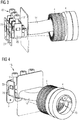
- Figures 3 and 4 show details of the line filter 1.
- neither the housing 3 of the line filter 1 nor the shunt components 5 are shown in Figures 3 and 4 to improve comprehensibility.
- IDC connectors 16, cable guide 14 and magnetic components 4 are all shown.
- Figure 5 shows a perspective view of another alternative design of the line filter 1.
- the housing 3 is shown as partially see-through to improve comprehensibility.
- the design shown in Figure 5 differs from the previously described design in the design of the guiding element 14.
- the guiding element 14 comprises multiple separate tubes 22 wherein a tube 22 is provided for each of the phases 11, 12, 13 of the system cable 2.
- Figure 6 shows a perspective view of the above discussed IDC 16.
- FIG. 7 shows an alternative design of the IDC 16.
- the conductive pin 18 is arranged at the side of the cage 20 which is opposite to the screw 17.
- the basic functionality of the IDC 16 is not changed.
- the screw 17 is tightened, the system cable 2 is thereby compressed between the platform 19 and the cage 20 and the conductive pin 18 is forced to pierce into the system cable 2 at the same time.
- the IDC 16 comprises two conductive pins 18.
- a first conductive pin 18 is arranged on the end of the screw 17 which faces towards the system cable 2 as also shown in the embodiment of Figure 6 .
- a second conductive pin 18 is arranged at the side of the cage 20 which is opposite to the screw 17 as also shown in the embodiment of Figure 7 .
Landscapes
- Engineering & Computer Science (AREA)
- Power Engineering (AREA)
- Details Of Connecting Devices For Male And Female Coupling (AREA)
- Filters And Equalizers (AREA)
- Shielding Devices Or Components To Electric Or Magnetic Fields (AREA)
- Connections By Means Of Piercing Elements, Nuts, Or Screws (AREA)
Claims (13)
- Filtre (1) de ligne,
celui-ci étant configuré pour être installé sur un câble (2) de système,
le filtre (1) de ligne comportant un composant magnétique (4),
le filtre (1) de ligne définissant un chemin (6) de câble à travers le filtre (1) de ligne,
le filtre (1) de ligne étant configuré pour permettre une mise en place du câble (2) de système le long du chemin (6) de câble au moment d'une installation, assurant ainsi un couplage magnétique du câble (2) de système au composant magnétique (4), et
le filtre (1) de ligne comportant un connecteur (16) à déplacement d'isolation et un composant (5) de dérivation,
le connecteur (16) à déplacement d'isolation étant configuré pour être serré au moment de l'installation, assurant ainsi une liaison galvanique du câble (2) de système au composant (5) de dérivation,
le composant magnétique (4) étant un noyau d'inductance, le filtre (1) de ligne comportant un boîtier (3),
le connecteur (16) à déplacement d'isolation étant disposé entièrement à l'intérieur du boîtier (3),
le composant magnétique (4) étant en forme de bague et comportant une ouverture (15), et
le chemin (6) de câble passant à travers l'ouverture (15) du composant magnétique (4),
caractérisé en ce que le filtre (1) de ligne comporte un élément (14) de guidage qui comporte un tube unique servant à guider de multiples phases (11, 12, 13) du câble (2) de système, ou comporte de multiples tubes (22) distincts servant à guider les phases (11, 12, 13) respectives du câble (2) de système,
l'élément (14) de guidage étant configuré pour guider mécaniquement le câble (2) de système le long du chemin (6) de câble pendant la mise en place du câble (2) de système le long du chemin (6) de câble et pour maintenir le câble (2) de système dans le chemin (6) de câble une fois le câble (2) de système mis en place le long du chemin (6) de câble ; et
l'élément (14) de guidage étant configuré pour maintenir le câble (2) de système dans sa position le long du chemin (6) de câble. - Filtre (1) de ligne selon la revendication 1,
le filtre (1) de ligne comportant un orifice (9a, 9b, 9c, 10) qui est configuré pour permettre la mise en place du câble (2) de système le long du chemin (6) de câble en poussant le câble (2) de système à travers l'orifice (9a, 9b, 9c, 10) au moment de l'installation. - Filtre (1) de ligne selon l'une des revendications précédentes,
le connecteur (16) à déplacement d'isolation comportant une vis (17) et au moins une broche conductrice (18) qui est configurée pour perforer le câble (2) de système lorsque la vis (17) est serrée. - Filtre (1) de ligne selon la revendication 3,
dans lequel la broche (18) est disposée à l'extrémité de la vis (17) qui est configurée pour faire face au câble (2) de système,
soit dans lequel la broche (18) est disposée de façon à se trouver du côté du câble (2) de système qui est opposé à la vis (17) lorsque le filtre (1) de ligne est installé sur le câble (2) de système. - Filtre (1) de ligne selon la revendication 3 ou 4, la broche conductrice (18) étant configurée pour perforer le câble (2) de système et faire saillie dans le câble (2) de système avec une profondeur située dans la plage allant de 0,01 mm à 20 mm.
- Filtre (1) de ligne selon l'une des revendications précédentes,
le filtre (1) de ligne étant exempt d'enroulements conducteurs internes. - Filtre (1) de ligne selon l'une des revendications précédentes,
le connecteur (16) à déplacement d'isolation étant configuré pour prélever un courant de dérivation à partir du câble (2) de système à travers la liaison galvanique du câble (2) de système au composant (5) de dérivation,
le courant de dérivation étant inférieur à un courant circulant à travers le câble (2) de système. - Filtre (1) de ligne selon la revendication 7,
le courant de dérivation étant situé dans la plage allant de 0,1 A à 10 A. - Filtre (1) de ligne selon l'une des revendications précédentes,
comportant de multiples connecteurs (16) à déplacement d'isolation,
chacun des connecteurs (16) à déplacement d'isolation étant configuré pour être serré au moment de l'installation, assurant ainsi des liaisons galvaniques du câble (2) de système au composant (5) de dérivation. - Filtre (1) de ligne selon l'une des revendications précédentes,
celui-ci étant configuré pour être installé sur un câble (2) de système qui comporte au moins une phase (11, 12, 13),
le filtre (1) de ligne étant configuré de telle façon que toutes les phases (11, 12, 13) du câble (2) de système soient reliées magnétiquement au composant magnétique (4) lorsque le câble (2) de système est mis en place le long du chemin (6) de câble, et
le filtre (1) de ligne étant configuré pour permettre de relier galvaniquement chaque phase (11, 12, 13) du câble (2) de système à au moins un connecteur (16) à déplacement d'isolation. - Filtre (1) de ligne selon l'une des revendications précédentes,
le filtre (1) de ligne étant configuré pour permettre de désinstaller le filtre (1) de ligne du câble (2) de système. - Ensemble comportant un filtre (1) de ligne selon l'une des revendications précédentes et un câble (2) de système.
- Procédé d'installation d'un filtre (1) de ligne sur un câble (2) de système,
le filtre (1) de ligne comportant un composant magnétique (4), un connecteur (16) à déplacement d'isolation et un composant (5) de dérivation,
le procédé comportant les étapes consistant à :- mettre en place le câble (2) de système le long d'un chemin (6) de câble défini à travers le filtre (1) de ligne, assurant ainsi un couplage magnétique du câble (2) de système au composant magnétique (4), et- serrer le connecteur (16) à déplacement d'isolation autour du câble (2) de système, assurant ainsi une liaison galvanique du câble (2) de système au composant (5) de dérivation,le composant magnétique (4) étant un noyau d'inductance, le filtre (1) de ligne comportant un boîtier (3),
le connecteur (16) à déplacement d'isolation étant disposé entièrement à l'intérieur du boîtier (3) ;
le composant magnétique (4) étant en forme de bague et comportant une ouverture (15),
le chemin (6) de câble passant à travers l'ouverture (15) du composant magnétique (4),
caractérisé en ce que le filtre (1) de ligne comporte un élément (14) de guidage qui comporte un tube unique dans lequel de multiple phases (11, 12, 13) du câble (2) de système sont guidées, ou qui comporte de multiples tubes (22) distincts servant à guider les phases (11, 12, 13) respectives du câble (2) de système,
l'élément (14) de guidage étant configuré pour guider mécaniquement le câble (2) de système le long du chemin (6) de câble pendant la mise en place du câble (2) de système le long du chemin (6) de câble et pour maintenir le câble (2) de système dans le chemin (6) de câble une fois le câble (2) de système mis en place le long du chemin (6) de câble ; et
l'élément (14) de guidage maintenant le câble (2) de système dans sa position le long du chemin (6) de câble.
Applications Claiming Priority (2)
| Application Number | Priority Date | Filing Date | Title |
|---|---|---|---|
| EP14192512.3A EP3018766A1 (fr) | 2014-11-10 | 2014-11-10 | Filtre de ligne et procédé d'installation d'un filtre de ligne sur un câble de système |
| PCT/EP2015/075320 WO2016074955A1 (fr) | 2014-11-10 | 2015-10-30 | Filtre de ligne et procédé d'installation d'un filtre de ligne sur un câble de système |
Publications (2)
| Publication Number | Publication Date |
|---|---|
| EP3218969A1 EP3218969A1 (fr) | 2017-09-20 |
| EP3218969B1 true EP3218969B1 (fr) | 2021-04-14 |
Family
ID=51870902
Family Applications (2)
| Application Number | Title | Priority Date | Filing Date |
|---|---|---|---|
| EP14192512.3A Ceased EP3018766A1 (fr) | 2014-11-10 | 2014-11-10 | Filtre de ligne et procédé d'installation d'un filtre de ligne sur un câble de système |
| EP15793729.3A Active EP3218969B1 (fr) | 2014-11-10 | 2015-10-30 | Filtre de ligne et procédé d'installation d'un filtre de ligne sur un câble de système |
Family Applications Before (1)
| Application Number | Title | Priority Date | Filing Date |
|---|---|---|---|
| EP14192512.3A Ceased EP3018766A1 (fr) | 2014-11-10 | 2014-11-10 | Filtre de ligne et procédé d'installation d'un filtre de ligne sur un câble de système |
Country Status (5)
| Country | Link |
|---|---|
| US (1) | US10447224B2 (fr) |
| EP (2) | EP3018766A1 (fr) |
| JP (1) | JP6652564B2 (fr) |
| CN (1) | CN107112642B (fr) |
| WO (1) | WO2016074955A1 (fr) |
Families Citing this family (3)
| Publication number | Priority date | Publication date | Assignee | Title |
|---|---|---|---|---|
| DE102017113556C5 (de) | 2017-06-20 | 2023-06-22 | Tdk Electronics Ag | Filter-Bauteil |
| US11431114B2 (en) * | 2020-02-14 | 2022-08-30 | Te Connectivity Solutions Gmbh | Enclosed connection systems for forming an enclosed connection between conductors, and methods including same |
| CN111933421A (zh) * | 2020-09-15 | 2020-11-13 | 苏州汇川联合动力系统有限公司 | 支架、滤波结构及加工方法、电机控制器 |
Citations (2)
| Publication number | Priority date | Publication date | Assignee | Title |
|---|---|---|---|---|
| US5461351A (en) * | 1994-06-06 | 1995-10-24 | Shusterman; Boris | Common-mode filtering attachment for power line connectors |
| WO2009046762A1 (fr) * | 2007-10-10 | 2009-04-16 | Schaffner Emv Ag | Filtre emc |
Family Cites Families (15)
| Publication number | Priority date | Publication date | Assignee | Title |
|---|---|---|---|---|
| GB2153165A (en) * | 1984-01-20 | 1985-08-14 | Avx Corp | Connector assembly |
| US5630734A (en) * | 1995-12-13 | 1997-05-20 | General Motors Corporation | Connector with solderless filter |
| NZ514880A (en) * | 1999-04-01 | 2003-05-30 | Nor | Coupling apparatus and method |
| GB2354374B (en) * | 1999-09-07 | 2003-07-30 | David Malcolm Goodwin | Electric cable joints methods of and kits for making them |
| JP2002305422A (ja) | 2001-04-06 | 2002-10-18 | Mitsubishi Electric Corp | 電力線用フィルタ |
| JP2004147226A (ja) | 2002-10-25 | 2004-05-20 | Sumitomo Electric Ind Ltd | 通信用フィルタ |
| US7307495B2 (en) | 2004-06-17 | 2007-12-11 | Fci Americas Technology, Inc. | Electrical filter assembly having IDC connection |
| CN101073185A (zh) * | 2004-06-17 | 2007-11-14 | Fci公司 | 具有idc连接的电滤波器组件 |
| US7104832B2 (en) * | 2004-08-05 | 2006-09-12 | 3M Innovative Properties Company | Modular electrical connector and method of using |
| US7361055B2 (en) * | 2005-01-14 | 2008-04-22 | Molex Incorporated | Modular filter connector |
| JP4137895B2 (ja) * | 2005-02-02 | 2008-08-20 | Tdk株式会社 | ノイズ吸収装置 |
| US7561008B2 (en) * | 2006-10-31 | 2009-07-14 | Azure Dynamics, Inc. | Filter package |
| CN201877579U (zh) * | 2010-11-25 | 2011-06-22 | 单博雅 | 顶针式取电压装置 |
| JP5697238B2 (ja) * | 2010-12-13 | 2015-04-08 | 矢崎総業株式会社 | ワイヤハーネス |
| JP2014067600A (ja) * | 2012-09-26 | 2014-04-17 | Denso Wave Inc | プログラマブルロジックコントローラの電線接続装置 |
-
2014
- 2014-11-10 EP EP14192512.3A patent/EP3018766A1/fr not_active Ceased
-
2015
- 2015-10-30 US US15/525,576 patent/US10447224B2/en active Active
- 2015-10-30 WO PCT/EP2015/075320 patent/WO2016074955A1/fr not_active Ceased
- 2015-10-30 CN CN201580061070.0A patent/CN107112642B/zh active Active
- 2015-10-30 EP EP15793729.3A patent/EP3218969B1/fr active Active
- 2015-10-30 JP JP2017525048A patent/JP6652564B2/ja not_active Expired - Fee Related
Patent Citations (2)
| Publication number | Priority date | Publication date | Assignee | Title |
|---|---|---|---|---|
| US5461351A (en) * | 1994-06-06 | 1995-10-24 | Shusterman; Boris | Common-mode filtering attachment for power line connectors |
| WO2009046762A1 (fr) * | 2007-10-10 | 2009-04-16 | Schaffner Emv Ag | Filtre emc |
Also Published As
| Publication number | Publication date |
|---|---|
| JP6652564B2 (ja) | 2020-02-26 |
| CN107112642A (zh) | 2017-08-29 |
| EP3218969A1 (fr) | 2017-09-20 |
| WO2016074955A1 (fr) | 2016-05-19 |
| EP3018766A1 (fr) | 2016-05-11 |
| US20170338787A1 (en) | 2017-11-23 |
| US10447224B2 (en) | 2019-10-15 |
| JP2018504796A (ja) | 2018-02-15 |
| CN107112642B (zh) | 2019-12-20 |
Similar Documents
| Publication | Publication Date | Title |
|---|---|---|
| CN108092026B (zh) | 用于多芯线的电线缆的电的插接连接器 | |
| EP3761763A1 (fr) | Filtre avec ensemble de barre de bus | |
| CN108092027B (zh) | 用于多芯线的电缆的电插接连接器 | |
| US10355423B2 (en) | Hybrid connector assembly with integrated overvoltage protection | |
| EP3218969B1 (fr) | Filtre de ligne et procédé d'installation d'un filtre de ligne sur un câble de système | |
| WO2015005982A1 (fr) | Carte de circuit imprimé ayant des pastilles de terminaison à accès latéral | |
| EP3014708B1 (fr) | Optimisation et standardisation d'icm pour l'automatisation | |
| US6087584A (en) | Tubular cable grounding mechanism | |
| CN106410543A (zh) | 配电装置 | |
| CN108092016B (zh) | 用于多芯线的电缆的电插接连接器 | |
| US11888255B2 (en) | Single pair ethernet connector | |
| US6314182B1 (en) | External filter box | |
| US5924877A (en) | Ground connector for rack-mount modules and methods of operation and manufacture therefor | |
| CN215525871U (zh) | 电磁辐射超标可拆接组合滤波电容的屏蔽实验电缆系统 | |
| CN220556625U (zh) | 取电线缆和作业机械 | |
| EP0174578B1 (fr) | Fiche d'appareil avec filtre électrique d'antiparasitage connecté à celle-ci | |
| US6290511B1 (en) | Grounding of snap switches in a wiring box | |
| EP4210177B1 (fr) | Connecteur double avec des bornes de connexion à déplacement d'isolation et de ressort | |
| WO2001059883A1 (fr) | Procede d'assemblage d'un connecteur a ajustement d'impedance | |
| CN222826716U (zh) | 一种扁平屏蔽线装置 | |
| CN218770452U (zh) | 一种带滤波功能的适配器和电子设备 | |
| KR100952046B1 (ko) | 단자가 없는 인버터 트랜스포머의 보빈구조 | |
| KR0144611B1 (ko) | 플라이백 트랜스포머의 포커스 유니트 인출 케이블 결합장치 | |
| CN117119726A (zh) | 一种插座式设备控制盒 | |
| KR20120085051A (ko) | 터미널 변형 방지형 다극 커넥터 |
Legal Events
| Date | Code | Title | Description |
|---|---|---|---|
| STAA | Information on the status of an ep patent application or granted ep patent |
Free format text: STATUS: THE INTERNATIONAL PUBLICATION HAS BEEN MADE |
|
| PUAI | Public reference made under article 153(3) epc to a published international application that has entered the european phase |
Free format text: ORIGINAL CODE: 0009012 |
|
| STAA | Information on the status of an ep patent application or granted ep patent |
Free format text: STATUS: REQUEST FOR EXAMINATION WAS MADE |
|
| 17P | Request for examination filed |
Effective date: 20170418 |
|
| AK | Designated contracting states |
Kind code of ref document: A1 Designated state(s): AL AT BE BG CH CY CZ DE DK EE ES FI FR GB GR HR HU IE IS IT LI LT LU LV MC MK MT NL NO PL PT RO RS SE SI SK SM TR |
|
| AX | Request for extension of the european patent |
Extension state: BA ME |
|
| RIN1 | Information on inventor provided before grant (corrected) |
Inventor name: TUCKER, ANDREW Inventor name: JARFAS, NORBERT |
|
| DAV | Request for validation of the european patent (deleted) | ||
| DAX | Request for extension of the european patent (deleted) | ||
| STAA | Information on the status of an ep patent application or granted ep patent |
Free format text: STATUS: EXAMINATION IS IN PROGRESS |
|
| 17Q | First examination report despatched |
Effective date: 20180227 |
|
| RAP1 | Party data changed (applicant data changed or rights of an application transferred) |
Owner name: EPCOS AG |
|
| RAP1 | Party data changed (applicant data changed or rights of an application transferred) |
Owner name: TDK ELECTRONICS AG |
|
| REG | Reference to a national code |
Ref country code: DE Ref legal event code: R079 Ref document number: 602015068152 Country of ref document: DE Free format text: PREVIOUS MAIN CLASS: H01R0013719000 Ipc: H02M0001120000 |
|
| RIC1 | Information provided on ipc code assigned before grant |
Ipc: H01R 4/2408 20180101ALI20201006BHEP Ipc: H01R 13/719 20110101ALN20201006BHEP Ipc: H02M 1/12 20060101AFI20201006BHEP |
|
| GRAP | Despatch of communication of intention to grant a patent |
Free format text: ORIGINAL CODE: EPIDOSNIGR1 |
|
| STAA | Information on the status of an ep patent application or granted ep patent |
Free format text: STATUS: GRANT OF PATENT IS INTENDED |
|
| RIC1 | Information provided on ipc code assigned before grant |
Ipc: H01R 13/719 20110101ALN20201029BHEP Ipc: H02M 1/12 20060101AFI20201029BHEP Ipc: H01R 4/2408 20180101ALI20201029BHEP |
|
| INTG | Intention to grant announced |
Effective date: 20201116 |
|
| GRAS | Grant fee paid |
Free format text: ORIGINAL CODE: EPIDOSNIGR3 |
|
| GRAA | (expected) grant |
Free format text: ORIGINAL CODE: 0009210 |
|
| STAA | Information on the status of an ep patent application or granted ep patent |
Free format text: STATUS: THE PATENT HAS BEEN GRANTED |
|
| AK | Designated contracting states |
Kind code of ref document: B1 Designated state(s): AL AT BE BG CH CY CZ DE DK EE ES FI FR GB GR HR HU IE IS IT LI LT LU LV MC MK MT NL NO PL PT RO RS SE SI SK SM TR |
|
| REG | Reference to a national code |
Ref country code: GB Ref legal event code: FG4D |
|
| REG | Reference to a national code |
Ref country code: CH Ref legal event code: EP |
|
| REG | Reference to a national code |
Ref country code: DE Ref legal event code: R096 Ref document number: 602015068152 Country of ref document: DE |
|
| REG | Reference to a national code |
Ref country code: IE Ref legal event code: FG4D |
|
| REG | Reference to a national code |
Ref country code: AT Ref legal event code: REF Ref document number: 1383353 Country of ref document: AT Kind code of ref document: T Effective date: 20210515 |
|
| REG | Reference to a national code |
Ref country code: LT Ref legal event code: MG9D |
|
| REG | Reference to a national code |
Ref country code: AT Ref legal event code: MK05 Ref document number: 1383353 Country of ref document: AT Kind code of ref document: T Effective date: 20210414 |
|
| REG | Reference to a national code |
Ref country code: NL Ref legal event code: MP Effective date: 20210414 |
|
| PG25 | Lapsed in a contracting state [announced via postgrant information from national office to epo] |
Ref country code: BG Free format text: LAPSE BECAUSE OF FAILURE TO SUBMIT A TRANSLATION OF THE DESCRIPTION OR TO PAY THE FEE WITHIN THE PRESCRIBED TIME-LIMIT Effective date: 20210714 Ref country code: AT Free format text: LAPSE BECAUSE OF FAILURE TO SUBMIT A TRANSLATION OF THE DESCRIPTION OR TO PAY THE FEE WITHIN THE PRESCRIBED TIME-LIMIT Effective date: 20210414 Ref country code: HR Free format text: LAPSE BECAUSE OF FAILURE TO SUBMIT A TRANSLATION OF THE DESCRIPTION OR TO PAY THE FEE WITHIN THE PRESCRIBED TIME-LIMIT Effective date: 20210414 Ref country code: FI Free format text: LAPSE BECAUSE OF FAILURE TO SUBMIT A TRANSLATION OF THE DESCRIPTION OR TO PAY THE FEE WITHIN THE PRESCRIBED TIME-LIMIT Effective date: 20210414 Ref country code: LT Free format text: LAPSE BECAUSE OF FAILURE TO SUBMIT A TRANSLATION OF THE DESCRIPTION OR TO PAY THE FEE WITHIN THE PRESCRIBED TIME-LIMIT Effective date: 20210414 Ref country code: NL Free format text: LAPSE BECAUSE OF FAILURE TO SUBMIT A TRANSLATION OF THE DESCRIPTION OR TO PAY THE FEE WITHIN THE PRESCRIBED TIME-LIMIT Effective date: 20210414 |
|
| PG25 | Lapsed in a contracting state [announced via postgrant information from national office to epo] |
Ref country code: IS Free format text: LAPSE BECAUSE OF FAILURE TO SUBMIT A TRANSLATION OF THE DESCRIPTION OR TO PAY THE FEE WITHIN THE PRESCRIBED TIME-LIMIT Effective date: 20210814 Ref country code: GR Free format text: LAPSE BECAUSE OF FAILURE TO SUBMIT A TRANSLATION OF THE DESCRIPTION OR TO PAY THE FEE WITHIN THE PRESCRIBED TIME-LIMIT Effective date: 20210715 Ref country code: LV Free format text: LAPSE BECAUSE OF FAILURE TO SUBMIT A TRANSLATION OF THE DESCRIPTION OR TO PAY THE FEE WITHIN THE PRESCRIBED TIME-LIMIT Effective date: 20210414 Ref country code: NO Free format text: LAPSE BECAUSE OF FAILURE TO SUBMIT A TRANSLATION OF THE DESCRIPTION OR TO PAY THE FEE WITHIN THE PRESCRIBED TIME-LIMIT Effective date: 20210714 Ref country code: PL Free format text: LAPSE BECAUSE OF FAILURE TO SUBMIT A TRANSLATION OF THE DESCRIPTION OR TO PAY THE FEE WITHIN THE PRESCRIBED TIME-LIMIT Effective date: 20210414 Ref country code: PT Free format text: LAPSE BECAUSE OF FAILURE TO SUBMIT A TRANSLATION OF THE DESCRIPTION OR TO PAY THE FEE WITHIN THE PRESCRIBED TIME-LIMIT Effective date: 20210816 Ref country code: SE Free format text: LAPSE BECAUSE OF FAILURE TO SUBMIT A TRANSLATION OF THE DESCRIPTION OR TO PAY THE FEE WITHIN THE PRESCRIBED TIME-LIMIT Effective date: 20210414 Ref country code: RS Free format text: LAPSE BECAUSE OF FAILURE TO SUBMIT A TRANSLATION OF THE DESCRIPTION OR TO PAY THE FEE WITHIN THE PRESCRIBED TIME-LIMIT Effective date: 20210414 |
|
| REG | Reference to a national code |
Ref country code: DE Ref legal event code: R097 Ref document number: 602015068152 Country of ref document: DE |
|
| PG25 | Lapsed in a contracting state [announced via postgrant information from national office to epo] |
Ref country code: SK Free format text: LAPSE BECAUSE OF FAILURE TO SUBMIT A TRANSLATION OF THE DESCRIPTION OR TO PAY THE FEE WITHIN THE PRESCRIBED TIME-LIMIT Effective date: 20210414 Ref country code: SM Free format text: LAPSE BECAUSE OF FAILURE TO SUBMIT A TRANSLATION OF THE DESCRIPTION OR TO PAY THE FEE WITHIN THE PRESCRIBED TIME-LIMIT Effective date: 20210414 Ref country code: CZ Free format text: LAPSE BECAUSE OF FAILURE TO SUBMIT A TRANSLATION OF THE DESCRIPTION OR TO PAY THE FEE WITHIN THE PRESCRIBED TIME-LIMIT Effective date: 20210414 Ref country code: DK Free format text: LAPSE BECAUSE OF FAILURE TO SUBMIT A TRANSLATION OF THE DESCRIPTION OR TO PAY THE FEE WITHIN THE PRESCRIBED TIME-LIMIT Effective date: 20210414 Ref country code: EE Free format text: LAPSE BECAUSE OF FAILURE TO SUBMIT A TRANSLATION OF THE DESCRIPTION OR TO PAY THE FEE WITHIN THE PRESCRIBED TIME-LIMIT Effective date: 20210414 Ref country code: ES Free format text: LAPSE BECAUSE OF FAILURE TO SUBMIT A TRANSLATION OF THE DESCRIPTION OR TO PAY THE FEE WITHIN THE PRESCRIBED TIME-LIMIT Effective date: 20210414 Ref country code: RO Free format text: LAPSE BECAUSE OF FAILURE TO SUBMIT A TRANSLATION OF THE DESCRIPTION OR TO PAY THE FEE WITHIN THE PRESCRIBED TIME-LIMIT Effective date: 20210414 |
|
| PLBE | No opposition filed within time limit |
Free format text: ORIGINAL CODE: 0009261 |
|
| STAA | Information on the status of an ep patent application or granted ep patent |
Free format text: STATUS: NO OPPOSITION FILED WITHIN TIME LIMIT |
|
| 26N | No opposition filed |
Effective date: 20220117 |
|
| REG | Reference to a national code |
Ref country code: CH Ref legal event code: PL |
|
| PG25 | Lapsed in a contracting state [announced via postgrant information from national office to epo] |
Ref country code: IS Free format text: LAPSE BECAUSE OF FAILURE TO SUBMIT A TRANSLATION OF THE DESCRIPTION OR TO PAY THE FEE WITHIN THE PRESCRIBED TIME-LIMIT Effective date: 20210814 Ref country code: AL Free format text: LAPSE BECAUSE OF FAILURE TO SUBMIT A TRANSLATION OF THE DESCRIPTION OR TO PAY THE FEE WITHIN THE PRESCRIBED TIME-LIMIT Effective date: 20210414 |
|
| REG | Reference to a national code |
Ref country code: BE Ref legal event code: MM Effective date: 20211031 |
|
| GBPC | Gb: european patent ceased through non-payment of renewal fee |
Effective date: 20211030 |
|
| PG25 | Lapsed in a contracting state [announced via postgrant information from national office to epo] |
Ref country code: MC Free format text: LAPSE BECAUSE OF FAILURE TO SUBMIT A TRANSLATION OF THE DESCRIPTION OR TO PAY THE FEE WITHIN THE PRESCRIBED TIME-LIMIT Effective date: 20210414 |
|
| PG25 | Lapsed in a contracting state [announced via postgrant information from national office to epo] |
Ref country code: LU Free format text: LAPSE BECAUSE OF NON-PAYMENT OF DUE FEES Effective date: 20211030 Ref country code: IT Free format text: LAPSE BECAUSE OF FAILURE TO SUBMIT A TRANSLATION OF THE DESCRIPTION OR TO PAY THE FEE WITHIN THE PRESCRIBED TIME-LIMIT Effective date: 20210414 Ref country code: GB Free format text: LAPSE BECAUSE OF NON-PAYMENT OF DUE FEES Effective date: 20211030 Ref country code: BE Free format text: LAPSE BECAUSE OF NON-PAYMENT OF DUE FEES Effective date: 20211031 |
|
| PG25 | Lapsed in a contracting state [announced via postgrant information from national office to epo] |
Ref country code: LI Free format text: LAPSE BECAUSE OF NON-PAYMENT OF DUE FEES Effective date: 20211031 Ref country code: CH Free format text: LAPSE BECAUSE OF NON-PAYMENT OF DUE FEES Effective date: 20211031 |
|
| PG25 | Lapsed in a contracting state [announced via postgrant information from national office to epo] |
Ref country code: FR Free format text: LAPSE BECAUSE OF NON-PAYMENT OF DUE FEES Effective date: 20211031 |
|
| PG25 | Lapsed in a contracting state [announced via postgrant information from national office to epo] |
Ref country code: IE Free format text: LAPSE BECAUSE OF NON-PAYMENT OF DUE FEES Effective date: 20211030 |
|
| PG25 | Lapsed in a contracting state [announced via postgrant information from national office to epo] |
Ref country code: HU Free format text: LAPSE BECAUSE OF FAILURE TO SUBMIT A TRANSLATION OF THE DESCRIPTION OR TO PAY THE FEE WITHIN THE PRESCRIBED TIME-LIMIT; INVALID AB INITIO Effective date: 20151030 |
|
| P01 | Opt-out of the competence of the unified patent court (upc) registered |
Effective date: 20230521 |
|
| PG25 | Lapsed in a contracting state [announced via postgrant information from national office to epo] |
Ref country code: CY Free format text: LAPSE BECAUSE OF FAILURE TO SUBMIT A TRANSLATION OF THE DESCRIPTION OR TO PAY THE FEE WITHIN THE PRESCRIBED TIME-LIMIT Effective date: 20210414 |
|
| PGFP | Annual fee paid to national office [announced via postgrant information from national office to epo] |
Ref country code: DE Payment date: 20231020 Year of fee payment: 9 |
|
| PG25 | Lapsed in a contracting state [announced via postgrant information from national office to epo] |
Ref country code: MK Free format text: LAPSE BECAUSE OF FAILURE TO SUBMIT A TRANSLATION OF THE DESCRIPTION OR TO PAY THE FEE WITHIN THE PRESCRIBED TIME-LIMIT Effective date: 20210414 |
|
| PG25 | Lapsed in a contracting state [announced via postgrant information from national office to epo] |
Ref country code: MT Free format text: LAPSE BECAUSE OF FAILURE TO SUBMIT A TRANSLATION OF THE DESCRIPTION OR TO PAY THE FEE WITHIN THE PRESCRIBED TIME-LIMIT Effective date: 20210414 |
|
| REG | Reference to a national code |
Ref country code: DE Ref legal event code: R119 Ref document number: 602015068152 Country of ref document: DE |
|
| PG25 | Lapsed in a contracting state [announced via postgrant information from national office to epo] |
Ref country code: DE Free format text: LAPSE BECAUSE OF NON-PAYMENT OF DUE FEES Effective date: 20250501 |
|
| PG25 | Lapsed in a contracting state [announced via postgrant information from national office to epo] |
Ref country code: TR Free format text: LAPSE BECAUSE OF FAILURE TO SUBMIT A TRANSLATION OF THE DESCRIPTION OR TO PAY THE FEE WITHIN THE PRESCRIBED TIME-LIMIT Effective date: 20210414 |