EP3219237B1 - Plaque de maintien dotee d'une fermeture amelioree - Google Patents
Plaque de maintien dotee d'une fermeture amelioree Download PDFInfo
- Publication number
- EP3219237B1 EP3219237B1 EP16160969.8A EP16160969A EP3219237B1 EP 3219237 B1 EP3219237 B1 EP 3219237B1 EP 16160969 A EP16160969 A EP 16160969A EP 3219237 B1 EP3219237 B1 EP 3219237B1
- Authority
- EP
- European Patent Office
- Prior art keywords
- elastic element
- holding plate
- closure flap
- cover
- base plate
- Prior art date
- Legal status (The legal status is an assumption and is not a legal conclusion. Google has not performed a legal analysis and makes no representation as to the accuracy of the status listed.)
- Active
Links
Images


Classifications
-
- A—HUMAN NECESSITIES
- A47—FURNITURE; DOMESTIC ARTICLES OR APPLIANCES; COFFEE MILLS; SPICE MILLS; SUCTION CLEANERS IN GENERAL
- A47L—DOMESTIC WASHING OR CLEANING; SUCTION CLEANERS IN GENERAL
- A47L9/00—Details or accessories of suction cleaners, e.g. mechanical means for controlling the suction or for effecting pulsating action; Storing devices specially adapted to suction cleaners or parts thereof; Carrying-vehicles specially adapted for suction cleaners
- A47L9/10—Filters; Dust separators; Dust removal; Automatic exchange of filters
- A47L9/14—Bags or the like; Rigid filtering receptacles; Attachment of, or closures for, bags or receptacles
- A47L9/1427—Means for mounting or attaching bags or filtering receptacles in suction cleaners; Adapters
- A47L9/1436—Connecting plates, e.g. collars, end closures
- A47L9/1445—Connecting plates, e.g. collars, end closures with closure means
- A47L9/1454—Self-sealing closures, e.g. valves
Definitions
- the invention relates to a holding plate for a vacuum cleaner filter bag, in particular for arranging the vacuum cleaner filter bag in a vacuum cleaner housing.
- Such retaining plates are known in many forms. Many known retaining plates also have closure devices so that the passage opening can be closed in the bag after use of the bag to prevent accidental leakage of the material to be aspirated.
- closure devices For the shutter mechanism different solutions have been proposed, such as slider solutions as in EP 0 758 209 , Folding solutions as in the DE 10 2011 105 384 or membrane solutions as in the FR 2 721 188 ,
- flaps are often spring elements use that push the flaps after use in the closed position or pull.
- leaf springs as in the EP 2 123 206
- From the DE 20 2013 100 862 , of the DE 10 2008 046 200 and the DE 10 2006 037 456 are more spring elements known.
- the spring elements are arranged in the filter bag, as in the DE 10 2011 008 117 or the DE 20 2015 101 218 but can also be arranged outside the filter bag as in the EP 1 480 545 ,
- the object of the invention is therefore to provide a holding plate which has a functionally reliable solution for closing the passage opening, which is inexpensive to realize even in mass production.
- the inventors of the present application have recognized that problems with regard to the closure function in known holding plates are often attributable to the fact that dust or other foreign bodies settle in the area of the spring elements, so that they can only insufficiently apply the necessary spring force to the closing flap ,
- the present invention prevents or reduces the deposition of such interference elements in that the elastic element is at least partially covered by the cover element and thus shielded from the environment. In operation, therefore, no or less contaminants enter areas of the spring where such contaminants could adversely affect the function of the elastic element. The reliability of the closure mechanism is thereby improved.
- the solution is also easy to implement, so that it can be implemented cost-effectively in mass production.
- the closure flap is biased in the closed position. This means that a force must be used to open the flap. This force can be exerted by a neck of the vacuum cleaner and / or the air flow flowing into the bag. When the flap is in the open position, it is acted upon by the elastic element in the closing direction with a force. After eliminating the force acting in the opening direction, this force causes the closure flap to return to the closed position.
- the closure flap can be connected via a joint, in particular a film hinge, with parts of the holding plate, in particular the base plate.
- the closure flap may have a shape that corresponds to the shape of the passage opening.
- the cover element separates the elastic element partially or completely from the environment.
- the cover element overlaps the elastic element at least partially in plan view of the holding plate on the side on which the elastic element is arranged.
- the cover member may be spaced from the elastic member. In this case, the cover member overlaps the elastic member without touching it. But it is also possible that the cover member contacts the elastic element, at least partially and / or during parts of the opening and / or closing movement of the closure flap.
- a volume can be defined within which the elastic element is arranged partially or completely.
- a cavity for receiving the elastic element can be formed by the cover.
- the cover element can be arranged such that it does not overlap or cover the areas of the passage opening released by the closure flap when the closure flap is open (seen in the direction of flow). In other words, the cover element can be arranged so that it overlaps or covers the passage opening only in areas in which they are also overlapped or covered by the closure flap.
- the maximum distance between the elastic element and a surface of the cover element facing the elastic element may be smaller than the diameter of the closure flap, in particular smaller than half the diameter of the closure flap. If the flap does not have a constant diameter, the average diameter may be used as the diameter.
- the elastic element may be any spring element, for example a coil spring, a leg spring, a leaf spring or a cambered leaf spring.
- the retaining plate can be attached to a holding device in a vacuum cleaner housing.
- the vacuum cleaner filter bag with the help of the holding plate via a vacuum cleaner side connecting piece be pushed.
- the elastic element can be arranged in the closing direction in front of the closure flap. In the opening direction, the elastic element is then arranged behind the closure flap.
- the elastic element can be arranged on the side of the holding plate which is provided for connection to the bag wall of the vacuum cleaner filter bag. If the holding plate is connected to a vacuum cleaner filter bag, so that is the elastic element in the dust chamber, ie in the interior of the vacuum cleaner filter bag. There, the risk that the function of the elastic element is affected by impurities is particularly high. Thus, the use of the cover according to the invention is particularly advantageous here.
- the elastic member When the cover member completely covers the elastic member, the elastic member can be completely separated from the dust space.
- cover element covers the elastic element only partially, in particular areas of the elastic element can be covered, in which impurities could lead to a reduction of the spring force in the closing direction.
- Such effective areas may be, in particular, areas of the elastic element which exert a spring force on the closure flap, or areas which directly adjoin fastening devices of the elastic element on parts of the holding plate. Contamination can occur in these storage areas cause the distance between the elastic element and the closure flap to increase in the closed position. As a result, the elastic element can no longer provide the full spring force.
- areas of the elastic element may be covered, in which the elastic element cooperates with holding elements which hold the elastic element in the open and / or closed position of the closure flap in a predetermined position.
- the cover member may comprise a film, a nonwoven fabric and / or a paper.
- the film may in particular be an elastic film, which comprises, for example, a thermoplastic elastomer or consists of such.
- the cover element comprises a laminate of different materials, for example comprising a nonwoven fabric and a film or a paper and a film. It has been found that with such cover elements, the movement of the flap and of the elastic element during opening and closing of the closure flap is not significantly impaired.
- the cover member may be formed as a separate component which is releasably or non-destructively releasably connected to a part of the base plate, the closure flap and / or the elastic member.
- the cover can be glued or welded to a part of the support plate, in particular with a part of the base plate.
- welding in particular an ultrasonic welding can be used.
- the cover is molded onto a part of the holding plate, in particular a part of the base plate.
- this is possible via a two-component injection molding process, in particular if the cover element contains or consists of an elastomer.
- a positive connection for example in the form of a "snap fit" or a frictional connection are conceivable.
- the cover is connected only to the elastic element, in particular glued to it, positively connected and / or non-positively connected.
- the cover element rests in a surface region of the base plate and / or closure flap on the base plate and / or closure flap, which surrounds the elastic element completely or at least on two sides. This at least partially prevents suction material from reaching the elastic element laterally.
- the cover element may have an embossment, which is particularly adapted to the shape of the elastic element. It can thereby be achieved that the elastic element is even less restricted in its movement during the opening of the closure flap.
- the cover element may also be pleated or creped for this purpose.
- the cover may be in the form of a bellows. It is possible that the bellows surrounds the elastic element only partially radially, for example, only in the half-space, which points away from the base plate and / or flap.
- the embossing can be produced by hot or cold embossing or by forming, for example deep drawing or vacuum drawing. Particularly preferred is the embossing by means of ultrasonic embossing. This procedure is very fast.
- the cover member may also be an injection molded part or a deep-drawn part. This can in turn be cohesively, non-positively or positively connected to parts of the retaining plate.
- the cover can also be formed in several pieces. This can be advantageous if the material used for the cover element is relatively stiff.
- Parts of the multi-part cover member may be positively or materially connected to each other, for example by welding, gluing or a "snap-fit" connection. But it is also possible that the parts of the multi-piece cover member are not connected to each other.
- the cover member may also comprise a pivot axis about which a part of the cover member is pivotable, in particular wherein the pivot axis is formed by a film hinge. Also by this measure, the strength of the cover can be taken into account.
- the elastic element may comprise an elastomer or consist of an elastomer.
- suction material can also be deposited between the turns of the spring, which impairs the action of the spring. If the elastic element comprises an elastomer or consists of an elastomer, this negative influence on the spring effect can be reduced or avoided.
- the elastomer may in particular comprise or be vulcanized silicone elastomer.
- crosslinked liquid silicone liquid silicone rubber, LSR
- crosslinked solid silicone high-consistency rubber, HCR
- the elastic element may be formed in particular as an elastomeric cord or elastomeric band.
- the cross section of the elastomeric cord or the elastomeric band can be round, rectangular or square. However, other cross sections are conceivable. It is also conceivable that the elastic element is designed in the form of a hollow cylinder, that is hollow along its longitudinal axis. This material savings are possible.
- the elastic element comprises an elastomer or consists of an elastomer, it may also be molded on to a part of the retaining plate, in particular a part of the base plate.
- the elastic member is a coil spring, wherein the coil spring is at least partially surrounded by a sheath.
- the cover can therefore be designed in the form of a sheath. In this case, in particular the interspaces of the coil spring are protected from further contamination.
- a sheath is understood here to mean a cover element which surrounds the elastic element, in particular in the form of a helical spring, radially in full circumference. Along the longitudinal axis of the elastic element, the sheath may extend completely or only partially over the entire extent of the elastic element.
- a coil spring is understood herein to mean a spring in which the spring wire is wound in helical form.
- the shape of the spring can be cylindrical but also conical (cone spring).
- springs that include a coil spring for example, torsion springs are to be regarded as a helical spring.
- Coil springs are to be distinguished insofar from coil springs, in which a metal strip is wound in a plane curved in the screw line.
- the sheath may comprise a plastic, a nonwoven fabric and / or paper.
- nonwoven fabric is used according to the definition according to ISO standard ISO9092: 1988 or CEM standard EN29092.
- nonwoven fabric or nonwoven fabric and nonwoven fabric in the field of production of nonwoven fabrics are delimited from one another as follows and also to be understood in the sense of the present invention.
- To produce a nonwoven fabric fibers and / or filaments are used.
- the loose or loose and unbonded fibers and / or filaments are referred to as nonwoven or nonwoven web.
- nonwoven binding step such a nonwoven fabric finally forms a nonwoven which has sufficient strength to be wound into rolls, for example.
- a nonwoven fabric is self-supporting by the solidification.
- the sheath may consist of two foils, in particular plastic foils, between which the helical spring is arranged, wherein the region in which the spring is arranged is surrounded by a circumferential weld seam.
- the covering element described above can also serve for fastening the elastic element to the retaining plate.
- the elastic element can rest loosely on the base plate and be limited by the cover in its position to a predetermined range.
- the elastic element can be restricted in its movement by the cover element so that it can only assume positions in which it is possible to act on the closure flap with the spring force.
- the elastic element is fixed by the cover in position. Fixed in its position means in this context that the elastic element in the closed position of the closure flap can not be moved relative to the holding plate.
- the retaining plate described above may be formed in one piece or in several pieces.
- the holding plate may comprise a holding device and a separate closure device comprising the closure flap.
- the closure device can be connected or connectable directly or indirectly, for example via the bag wall of the vacuum cleaner filter bag and / or via a sealing membrane, to the holding device.
- the base plate may also be formed in several pieces.
- one part of the base plate may be part of the holding device and another part may be a part of the closure device.
- the invention also provides a vacuum cleaner filter bag comprising a bag wall and a support plate connected thereto as described above.
- the retaining plate may thus have one or more of the above features.
- the bag wall of the vacuum cleaner filter bag may comprise one or more filter material layers, in particular one or more nonwoven fabric layers.
- Vacuum cleaner filter bag with such Bag wall of several filter material layers are for example from the EP 2 011 556 or the EP 0 960 645 known.
- a material for the nonwoven fabric layers a wide variety of plastics can be used, for example polypropylene and / or polyester.
- the position of the bag wall to be connected to the holding plate may be a nonwoven layer.
- the bag wall may have a passage opening, in particular wherein the passage opening of the bag wall is arranged in alignment with the passage opening of the base plate. Through the passage opening in the base plate and the passage opening in the bag wall, an inflow opening can be formed, through which the air to be purified can flow into the interior of the vacuum cleaner filter bag.
- the invention also provides a method of manufacturing a retainer plate according to claim 15.
- the provision of the base plate and the closure flap can in particular comprise a production of the base plate and the closure flap by injection molding. It is also possible to form the base plate by deep drawing. In this case, the closure flap can be formed by injection molding as a separate element, and then directly or indirectly connected to the deep-drawn base plate.
- the arrangement of the elastic element on the base plate and / or the closure flap may comprise a connection of the elastic element to the base plate and / or the closure flap, in particular by ultrasonic welding, gluing, or by a frictional or positive connection.
- the elastic element may be loosely placed on the base plate and / or the closure flap.
- the joining of the cover member with a part of the retaining plate can be done by gluing, welding or injection molding in an injection molding process as stated above.
- the cover can be connected to the base plate, the flap and / or the elastic element.
- the method may also include providing a separate cover member and then connecting the cover member to a portion of the support plate.
- FIG. 1 shows the schematic structure of an exemplary vacuum cleaner filter bag.
- the filter bag comprises a bag wall 1, a holding plate 2, as well as an inflow opening, through which the air to be filtered flows into the filter bag.
- the inflow opening is formed here by a passage opening 3 in the base plate of the holding plate 2 and a passage opening arranged in the bag wall 1 in alignment therewith.
- the holding plate 2 serves to fix the vacuum cleaner filter bag in a corresponding holding device in a housing of a vacuum cleaner.
- the bag wall 1 comprises at least one nonwoven fabric layer, for example of a melt-spun fine fiber spunbonded nonwoven fabric (meltblown nonwoven fabric) or a spunbonded nonwoven spunbonded nonwoven fabric.
- a melt-spun fine fiber spunbonded nonwoven fabric meltblown nonwoven fabric
- a spunbonded nonwoven spunbonded nonwoven fabric spunbonded nonwoven fabric
- the holding plate 2 comprises a base plate made of a plastic material, for example polypropylene.
- FIG. 2 A plan view of an exemplary holding plate used in conjunction with a filter bag as in FIG. 1 can be used as shown in FIG. 2 shown.
- the base plate of the holding plate 2 is here shown schematically rectangular, but may have any shapes that can correspond in particular with the corresponding holding device in the vacuum cleaner housing.
- the sealing lip 4 may comprise a thermoplastic elastomer, for example based on polypropylene, or consist thereof.
- the sealing lip 4 is intended to prevent or limit the escape of dust from the vacuum cleaner filter bag by sealing the area between the inner edge of the passage opening 3 and the outside of a connecting piece of the vacuum cleaner.
- the sealing lip shown here is only optional. It is also conceivable that the bag material of the vacuum cleaner filter bag itself is used as a sealing ring, as for example in the DE 102 03 460 is disclosed. The use of a sealing membrane between the holding plate 2 and bag wall 1, as in the EP 2 044 874 revealed is possible. It can also be provided no seal.
- FIG. 2 also shows a shutter 5, which is pivotable about a hinge 6.
- the joint 6 may in particular be a living hinge.
- the closure flap 5 serves to close the passage opening 3 when the vacuum cleaner is not in operation, in particular when the filter bag is removed from the vacuum cleaner.
- the closure flap 5 is biased by an elastic element 7 in the closed position.
- the elastic element 7 is connected in the region of a bearing 8 with the base plate of the retaining plate 2.
- the elastic element 7 is arranged in the closing direction in front of the closure flap 5.
- the top view of FIG. 2 takes place on the side of the holding plate 2, which is to be connected to the bag wall 1.
- the elastic element 7 is therefore located after connecting the holding plate 2 with the vacuum cleaner filter bag in the dust chamber, ie in the interior of the filter bag.
- the elastic element 7 may be, for example, a leaf spring, in particular a cambered leaf spring, a helical spring or an elastomeric element.
- a leaf spring in particular a cambered leaf spring, a helical spring or an elastomeric element.
- the retaining plate of FIG. 2 therefore, also includes a cover 9, which is connected to the base plate of the support plate 2 and the shutter 5 and the elastic member 7 toward the dust chamber, ie away from the base plate of the support plate 2 covers.
- the elastic element 7 is thus separated from the dust chamber or shielded from it.
- no or less suction material enters the region of the elastic element, in particular in the region immediately adjacent to the bearing 8, so that its function is not or less impaired.
- cover 9 is connected only to the base plate, and rests loosely on the closure flap 5. Also, a connection with the elastic member 7 is alternatively or additionally possible.
- the cover element may comprise a film, in particular an elastic film, for example of a thermoplastic elastomer.
- the film may have a thickness of less than 1 mm, in particular less than 0.5 mm, in particular less than 0.1 mm.
- the cover member 9 comprises or consists of a nonwoven fabric, a paper, or a fabric tape. A laminate of different materials, such as nonwoven fabric and film or paper and film is conceivable.
- the cover 9 may be releasably or non-destructively releasably connected to the base plate and / or the closure flap.
- the cover 9 may be glued or welded to the desired area of the base plate and / or the closure flap.
- the cover 9 may also have a self-adhesive area.
- a frictional or positive connection is possible, for example, a "snap-fit" connection (click connection).
- the cover 9 may also be connected via an injection molding process with the base plate and / or the closure flap 5.
- the cover 9 can be molded simultaneously with an optionally existing sealing lip 4 to the support plate 2.
- the cover 9 may in particular consist of the same material as the sealing lip 4, in particular of a thermoplastic elastomer.
- the cover member 9 comprises a film or a nonwoven fabric
- the film or the nonwoven fabric may be embossed.
- the cover member 9 can be given a shape conforming to the shape of the elastic member 7, so that the elastic member 7 is not limited or restricted in movement during opening of the shutter 5.
- the cover 9 may also be pleated or creped.
- the cover 9 may be formed in the form of a bellows. In this case, the folds of the pleated or creped cover element 9 can in particular run perpendicular to the direction of movement of the closure flap and / or of the elastic element.
- the embossing of the cover 9 can be done by hot or cold stamping or by deep drawing or Vakuumiana delight.
- the cover 9 may alternatively consist of an injection molded part or a deep-drawn part, which cohesively, positively or non-positively with the base plate, the Closure flap and / or the elastic member 7 is connected, in particular by gluing or welding.
- the cover element 9 has a rigidity which would oppose the mobility of the elastic element 7, the cover element 9 can also have a film hinge around which a part of the cover element 9 can be pivoted.
- the cover 9 can be made two or more pieces, wherein the parts of the multi-piece cover member are positively or materially connected to each other, in particular via welding, gluing or clicking (snap-fit).
- FIG. 3 shows a cross section through the exemplary holding plate 2 of FIG. 2 , It can be seen that the elastic element 7 is completely shielded by the cover 9 against the dust chamber, ie the environment that lies after the connection of the holding plate 2 with a filter bag in the interior of the filter bag.
- the elastic member 7 may be a coil spring.
- a cover in the form of a sheath may for example be arranged at least partially in a plastic film tube.
- the sheath can be easily formed by two plastic films which are circumferentially welded together with the coil spring between the two films. Also, a one-piece plastic tube can be pulled over the coil spring.
- the elastic element 7 can also be formed by an elastomeric cord or an elastomeric band.
- a vulcanized silicone elastomer can be used for the elastic element. This has the advantage that it can be molded onto the retaining plate.
- crosslinked liquid silicone liquid silicone rubber, LSR
- crosslinked solid silicone high-consistency rubber, HCR
- the elastic member made of an elastomer has inherent elasticity.
- the elastic element may also have a shape which imparts a further elasticity through its structure.
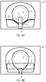
- FIG. 4A shows another example of a holding plate 2 with closure flap 5.
- the elastic element 10 extends transversely to the opening movement of the closure flap 5.
- Das elastic element 10 may in turn be formed in the form of a coil spring or an elastomeric band.
- a cover member 9 is again provided, which is connected in this case with the closure flap 5, the elastic element 10 but only partially covers.
- the cover element 9 in this example covers the region of the elastic element 10 which interacts with the closure flap 5 via a projection 11.
- This area is namely the functionally effective area for the application of force to the closure flap 5 via the elastic element 10.
- the projection 11 serves to hold the elastic element 10 in a holding position.
- FIG. 4B shows a further example of an arrangement of a cover 9.
- the cover 9 must be in this case mandatory elastic.
- the spring element In the open position of the flap 5, the spring element should be covered as much as possible.
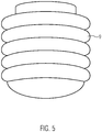
- FIG. 5 shows an example of a possible cover member 9, which is in particular pleated, that has several folds in the sense of a bellows. While a bellows is usually tubular, the cover 9 is, however, formed rather dome-shaped. By folding, it is possible to provide a relatively strong cover member without significantly disturbing the mobility of the underlying elastic member.
Landscapes
- Engineering & Computer Science (AREA)
- Mechanical Engineering (AREA)
- Filters For Electric Vacuum Cleaners (AREA)
Claims (15)
- Plaque de retenue (2) pour sac filtrant d'aspirateur, comprenant une plaque de base dans laquelle une ouverture de passage (3) est formée et un volet de fermeture (5) pour fermer l'ouverture de passage (3),
dans laquelle le volet de fermeture (5) est précontraint dans la position de fermeture par un élément élastique (7; 10),
caractérisée en ce qu'il est prévu un élément de couverture (9) relié à la plaque de base, au volet de fermeture (5) et/ou à l'élément élastique (7), qui couvre partiellement ou totalement l'élément élastique (7), dans lequel l'élément de couverture (9) est en contact avec le volet de fermeture (5) dans une zone de surface du volet de fermeture (5) qui entoure l'élément élastique (7; 10) au moins sur deux côtés. - Plaque de retenue (2) selon la revendication 1, dans laquelle l'élément élastique (7; 10) se situe, vu dans la direction de fermeture, devant le volet de fermeture (5).
- Plaque de retenue (2) selon la revendication 1 ou 2, dans laquelle l'élément de couverture (9) comprend une feuille, un non-tissé et/ou un papier.
- Plaque de retenue (2) selon l'une des revendications précédentes, dans laquelle l'élément de couverture (9) est collé ou soudé à une partie de la plaque de retenue (2), notamment de la plaque de base, ou est moulé par injection sur une partie de la plaque de retenue (2), notamment de la plaque de base.
- Plaque de retenue (2) selon l'une des revendications précédentes, dans laquelle l'élément de couverture (9) présente une empreinte qui est adaptée notamment à la forme de l'élément élastique (7).
- Plaque de retenue (2) selon l'une des revendications précédentes, dans laquelle l'élément de couverture (9) est plissé ou crêpé.
- Plaque de retenue (2) selon l'une des revendications précédentes, dans laquelle l'élément de couverture est réalisé en plusieurs pièces.
- Plaque de retenue (2) selon la revendication 7, dans laquelle les parties de l'élément de couverture en plusieurs pièces sont reliées les unes aux autres par concordance de forme ou par liaison de matière.
- Plaque de retenue (2) selon l'une des revendications précédentes, dans laquelle l'élément de couverture comprend un axe de pivotement autour duquel une partie de l'élément de couverture peut pivoter, notamment dans laquelle l'axe de pivotement est formé par une charnière-film.
- Plaque de retenue (2) selon l'une des revendications précédentes, dans laquelle l'élément élastique (7; 10) comprend un élastomère ou est formé d'un élastomère.
- Plaque de retenue (2) selon la revendication 10, dans laquelle l'élément élastique (7; 10) est moulé par injection sur une partie de la plaque de retenue (2), notamment de la plaque de base.
- Plaque de retenue (2) selon l'une des revendications 1-9, dans laquelle l'élément élastique (7; 10) est un ressort hélicoïdal et dans laquelle le ressort hélicoïdal est entouré, au moins en partie, par une enveloppe.
- Plaque de retenue (2) selon l'une des revendications précédentes, dans laquelle l'élément élastique (7; 10) repose librement sur la plaque de base et est limité dans sa position à une zone prédéterminée grâce à l'élément de couverture (9).
- Sac filtrant d'aspirateur comprenant une paroi de sac (1) et une plaque de retenue (2) selon l'une des revendications précédentes reliée à la paroi de sac.
- Procédé de fabrication d'une plaque de retenue (2) pour un sac filtrant d'aspirateur, comprenant les étapes consistant à :fournir une plaque de base pourvue d'une ouverture de passage (3) et fournir un volet de fermeture (5) pour fermer l'ouverture de passage (3) ;agencer un élément élastique (7; 10) sur la plaque de base et/ou le volet de fermeture (5) ; etrelier un élément de couverture (9) à la plaque de base, au volet de fermeture et/ou à l'élément élastique (7; 10), de façon que l'élément élastique (7; 10) soit couvert partiellement ou totalement au moyen de l'élément de couverture (9), dans lequel l'élément de couverture (9) est disposé de manière à être en contact avec le volet de fermeture (5) dans une zone de surface du volet de fermeture (5) qui entoure l'élément élastique (7; 10) au moins sur deux côtés.
Priority Applications (9)
| Application Number | Priority Date | Filing Date | Title |
|---|---|---|---|
| EP16160969.8A EP3219237B1 (fr) | 2016-03-17 | 2016-03-17 | Plaque de maintien dotee d'une fermeture amelioree |
| PL16160969T PL3219237T3 (pl) | 2016-03-17 | 2016-03-17 | Płytka mocująca z udoskonalonym elementem zamykającym |
| DK16160969.8T DK3219237T3 (en) | 2016-03-17 | 2016-03-17 | Holding plate with improved closure element |
| ES16160969.8T ES2673309T3 (es) | 2016-03-17 | 2016-03-17 | Placa de soporte con elemento de cierre mejorado |
| RU2018131846A RU2701569C1 (ru) | 2016-03-17 | 2017-03-16 | Удерживающая пластина с улучшенным закрывающим элементом |
| US16/085,409 US10939788B2 (en) | 2016-03-17 | 2017-03-16 | Retaining plate with improved sealing |
| AU2017235055A AU2017235055A1 (en) | 2016-03-17 | 2017-03-16 | Holding board with an improved closure element |
| CN201780025468.8A CN109068917B (zh) | 2016-03-17 | 2017-03-16 | 具有改善的密封的保持板 |
| PCT/EP2017/056228 WO2017158085A1 (fr) | 2016-03-17 | 2017-03-16 | Plaque de retenue présentant un élément de fermeture amélioré |
Applications Claiming Priority (1)
| Application Number | Priority Date | Filing Date | Title |
|---|---|---|---|
| EP16160969.8A EP3219237B1 (fr) | 2016-03-17 | 2016-03-17 | Plaque de maintien dotee d'une fermeture amelioree |
Publications (2)
| Publication Number | Publication Date |
|---|---|
| EP3219237A1 EP3219237A1 (fr) | 2017-09-20 |
| EP3219237B1 true EP3219237B1 (fr) | 2018-05-09 |
Family
ID=55542599
Family Applications (1)
| Application Number | Title | Priority Date | Filing Date |
|---|---|---|---|
| EP16160969.8A Active EP3219237B1 (fr) | 2016-03-17 | 2016-03-17 | Plaque de maintien dotee d'une fermeture amelioree |
Country Status (9)
| Country | Link |
|---|---|
| US (1) | US10939788B2 (fr) |
| EP (1) | EP3219237B1 (fr) |
| CN (1) | CN109068917B (fr) |
| AU (1) | AU2017235055A1 (fr) |
| DK (1) | DK3219237T3 (fr) |
| ES (1) | ES2673309T3 (fr) |
| PL (1) | PL3219237T3 (fr) |
| RU (1) | RU2701569C1 (fr) |
| WO (1) | WO2017158085A1 (fr) |
Family Cites Families (64)
| Publication number | Priority date | Publication date | Assignee | Title |
|---|---|---|---|---|
| US3533868A (en) | 1967-02-15 | 1970-10-13 | Cons Foods Corp | Method of manufacturing end closures for a vacuum cleaner dust bag |
| DE9016939U1 (de) | 1990-12-17 | 1991-04-04 | Wolfgang B. Schroeter GmbH, 4973 Vlotho | Filtereinrichtung für einen Staubsauger |
| DE4415350A1 (de) | 1994-05-02 | 1995-11-16 | Vorwerk Co Interholding | Staubfilterbeutel für einen Staubsauger |
| FR2721188B1 (fr) | 1994-06-21 | 1996-08-09 | Delphy | Dispositif de fermeture automatique d'un sac à poussière d'aspirateur par clapet. |
| DE29615163U1 (de) | 1996-08-31 | 1996-11-21 | Hafner, Ingo, Dipl.-Ing., 56566 Neuwied | Vorrichtung zur Aufnahme von Staub, Schmutz u.dgl. |
| IL139539A0 (en) | 1998-05-11 | 2004-02-08 | Airflo Europe Nv | Vacuum cleaner bag and improved vacuum cleaner bag |
| DE29924466U1 (de) | 1998-05-11 | 2003-05-28 | Airflo Europe N.V., Overpelt | Staubsaugerbeutel und verbesserter Staubsaugerbeutel |
| DE19919809C2 (de) | 1999-04-30 | 2003-02-06 | Fibermark Gessner Gmbh & Co | Staubfilterbeutel, enthaltend Nanofaservlies |
| US6372004B1 (en) | 1999-07-08 | 2002-04-16 | Airflo Europe N.V. | High efficiency depth filter and methods of forming the same |
| DE19948909A1 (de) | 1999-10-11 | 2001-04-12 | Vorwerk Co Interholding | Filterbeutel für einen Staubsauger |
| DE20010049U1 (de) | 2000-06-03 | 2000-09-14 | Aichner Filter GmbH, 92345 Dietfurt | Staubfilterbeutel, insbesondere für einen Staubsauger |
| DE20101466U1 (de) | 2001-01-27 | 2001-04-19 | Wolf GmbH, 32602 Vlotho | In einen Staubsauger einsetzbare Filtereinrichtung |
| DE10120223B4 (de) | 2001-04-24 | 2005-08-25 | Carl Freudenberg Kg | Mehrlagiger Luftfilter und dessen Verwendung |
| DE10209718A1 (de) | 2002-03-06 | 2003-09-25 | Edison Fatehpour | Federelement für eine Verschlussklappe einer Filtertüte |
| DE10221694B4 (de) | 2002-05-16 | 2018-07-12 | Branofilter Gmbh | Mehrlagiger Filteraufbau, Verwendung eines solchen mehrlagigen Filteraufbaus, Staubfilterbeutel, Taschenfilterbeutel, plissierter Filter, flächiger Abluftfilter und Luftfilter für Kraftfahrzeuge |
| WO2007059939A1 (fr) | 2005-11-22 | 2007-05-31 | Eurofilters Holding N.V. | Sac filtrant d'aspirateur et utilisation d'un sac filtrant d'aspirateur |
| DE502005006091D1 (de) | 2005-12-12 | 2009-01-08 | Inventus Engineering Gmbh | Energie absorbierendes Element |
| DE102005059214B4 (de) | 2005-12-12 | 2007-10-25 | Eurofilters N.V. | Filterbeutel für einen Staubsauger |
| US7938276B2 (en) | 2006-02-01 | 2011-05-10 | Mechanical Manufacturing Corporation | Filtration architecture for optimized performance |
| DE102006017553B3 (de) | 2006-04-13 | 2007-12-27 | Eurofilters N.V. | Filterbeutel für einen Staubsauger |
| ES2347091T3 (es) | 2006-04-25 | 2010-10-25 | Eurofilters Holding N.V. | Placa de sujecion para una bolsa de filtro de un aspirador de polvo. |
| EP1849392B1 (fr) | 2006-04-25 | 2008-10-08 | Eurofilters Holding N.V | Platine de fixation pour un sac à poussière d'un aspirateur |
| DE102006037456A1 (de) | 2006-08-10 | 2008-02-14 | Vorwerk & Co. Interholding Gmbh | Filterbeutel für einen Staubsauger |
| DE502006009062D1 (de) | 2006-11-03 | 2011-04-21 | Eurofilters Holding Nv | Antibakterieller Staubsaugerfilterbeutel |
| DE102006055890A1 (de) | 2006-11-27 | 2008-05-29 | Wolf Gmbh & Co. Kg | Verschlussvorrichtung für Filterbeutel und Verfahren zum Herstellen eines Filterbeutels mit einer Verschlussvorrichtung |
| ES2360415T5 (es) | 2007-07-06 | 2017-04-20 | Eurofilters Holding N.V. | Bolsa de filtro de aspiradora |
| DE102008046200B4 (de) | 2007-09-28 | 2016-09-15 | Vorwerk & Co. Interholding Gmbh | Filterbeutel für einen Staubsauger |
| DE202007014164U1 (de) | 2007-10-01 | 2007-12-13 | Branofilter Gmbh | Filterbeutel für Staubsauger |
| DE102007062028B4 (de) | 2007-12-21 | 2009-09-03 | Arwed Löseke Papierverarbeitung und Druckerei GmbH | Verfahren zur Herstellung eines Staubfilterbeutels und Staubfilterbeutel |
| DE202008003248U1 (de) | 2008-03-07 | 2008-05-08 | Eurofilters Holding N.V. | Staubsaugerfilterbeutel |
| ES2440722T3 (es) | 2008-03-07 | 2014-01-30 | Eurofilters Holding N.V. | Bolsa de filtro de aspiradora |
| US7972458B2 (en) | 2008-03-10 | 2011-07-05 | Uv Corporation | Filter material and process for producing same |
| DE202008006904U1 (de) * | 2008-05-21 | 2009-10-15 | Wolf Pvg Gmbh & Co. Kg | Halteplatte für einen Staubsaugerbeutel |
| DE202008004733U1 (de) | 2008-07-13 | 2008-10-02 | Wulbrandt, Herbert | Halteplatte für Staubsaugerbeutel mit automatischem Verschluss |
| DE102008041227A1 (de) | 2008-08-13 | 2010-02-18 | BSH Bosch und Siemens Hausgeräte GmbH | Staubsaugerbeutel |
| DE202008018054U1 (de) * | 2008-08-29 | 2011-04-28 | Vorwerk & Co. Interholding Gmbh | Filterbeutel für einen Staubsauger |
| CN101747596A (zh) | 2008-12-11 | 2010-06-23 | 王世和 | 回收聚酯切片微丝制备方法和用途 |
| ES2549756T3 (es) | 2009-06-19 | 2015-11-02 | Eurofilters N.V. | Bolsa plana para aspirador de polvo con al menos dos difusores |
| DE102009035717A1 (de) | 2009-07-31 | 2011-02-10 | Miele & Cie. Kg | Verfahren zur Anzeige eines Füllgrads eines Staubbeutels und Steuerungsvorrichtung zur Ausführung des Verfahrens |
| US8398752B2 (en) | 2009-08-04 | 2013-03-19 | Jerry M. Brownstein | High efficiency low pressure drop synthetic fiber based air filter made completely from post consumer waste materials |
| PL2301402T3 (pl) * | 2009-09-25 | 2014-06-30 | Eurofilters Holding Nv | Płyta nośna do worka filtrującego odkurzacza |
| ES2574157T3 (es) | 2009-10-19 | 2016-06-15 | Eurofilters Holding N.V. | Bolsa de filtro de aspiradora |
| DK2499285T3 (en) | 2009-11-13 | 2016-10-03 | Formfiber Denmark Aps | Non-woven fiber product comprising fibers of recycled material, |
| EP2662010B1 (fr) * | 2010-03-19 | 2014-08-06 | Eurofilters Holding N.V. | Sac d'aspirateur |
| DE102010060175A1 (de) * | 2010-09-06 | 2012-03-08 | Vorwerk & Co. Interholding Gmbh | Staubfilterbeutel |
| DE102010046567A1 (de) | 2010-09-27 | 2012-03-29 | Sandler Ag | Mehrlagiger Filteraufbau |
| DE102011008117A1 (de) | 2010-10-05 | 2012-04-05 | Herbert Wulbrandt | Verschluss einer Halteplatte für Staubsaugerbeutel und deren Fertigung |
| DE102010060353A1 (de) | 2010-11-04 | 2012-05-10 | Papierverarbeitung Görlitz GmbH | Staubfilterbeutel für Staubsauger |
| DE102011105384A1 (de) | 2011-06-20 | 2012-12-20 | Alexander Patzig | Halteplatte für Staubsaugerbeutel |
| DE202011052208U1 (de) * | 2011-12-06 | 2013-03-08 | Wolf Pvg Gmbh & Co. Kg | Haltevorrichtung für einen Staubsaugerbeutel |
| EP2606799B1 (fr) * | 2011-12-22 | 2015-02-25 | Eurofilters N.V. | Plaque de support |
| US20130177264A1 (en) | 2012-01-10 | 2013-07-11 | Fka Distributing Co., Llc | Fabric And Method of Producing Same |
| DE102012012999B4 (de) | 2012-01-24 | 2017-06-14 | Elku Bauteile GmbH | Halteplatte für Staubsaugerbeutel mit automatischem Verschluss mit einem elastischen Element |
| US9211491B2 (en) | 2012-11-06 | 2015-12-15 | Lydall, Inc. | Air filtration media and processes for manufacturing the same |
| DE102013012083A1 (de) * | 2012-11-19 | 2014-05-22 | Vorwerk & Co. Interholding Gmbh | Filterbeutel für einen Staubsauger |
| DE202013001096U1 (de) | 2013-02-05 | 2013-03-05 | Branofilter Gmbh | Staubfilterbeutel für Staubsauger |
| DE202013100862U1 (de) | 2013-02-28 | 2013-03-13 | Wolf Pvg Gmbh & Co. Kg | Halteplatte für einen Staubsaugerbeutel |
| DE202013103508U1 (de) | 2013-08-05 | 2013-08-22 | Wolf Pvg Gmbh & Co. Kg | Staubsaugerbeutel |
| DE202014100563U1 (de) | 2014-02-10 | 2015-05-15 | Wolf Pvg Gmbh & Co. Kg | Staubsaugerbeutel |
| CN104224049B (zh) * | 2014-09-19 | 2017-07-04 | 上海曾曦净化科技有限公司 | 一种用于吸尘器过滤袋的卡口板结构 |
| DE202015101218U1 (de) | 2015-03-10 | 2015-04-01 | Branofilter Gmbh | Staubfilterbeutel zum Einsatz in einem Staubsauggerät |
| EP3219374B1 (fr) | 2016-03-17 | 2019-05-08 | Eurofilters N.V. | Sac d'aspirateur en materiaux synthetiques recycles |
| ES2668626T3 (es) | 2016-03-17 | 2018-05-21 | Eurofilters N.V. | Bolsa de filtro de aspiradora con materiales textiles reciclados y/o línteres de algodón |
| PL3219376T3 (pl) | 2016-03-17 | 2019-04-30 | Eurofilters Nv | Worek filtracyjny do odkurzacza z pochodzących z recyklingu tworzyw sztucznych |
-
2016
- 2016-03-17 EP EP16160969.8A patent/EP3219237B1/fr active Active
- 2016-03-17 DK DK16160969.8T patent/DK3219237T3/en active
- 2016-03-17 ES ES16160969.8T patent/ES2673309T3/es active Active
- 2016-03-17 PL PL16160969T patent/PL3219237T3/pl unknown
-
2017
- 2017-03-16 WO PCT/EP2017/056228 patent/WO2017158085A1/fr not_active Ceased
- 2017-03-16 RU RU2018131846A patent/RU2701569C1/ru active
- 2017-03-16 US US16/085,409 patent/US10939788B2/en active Active
- 2017-03-16 CN CN201780025468.8A patent/CN109068917B/zh active Active
- 2017-03-16 AU AU2017235055A patent/AU2017235055A1/en not_active Abandoned
Non-Patent Citations (1)
| Title |
|---|
| None * |
Also Published As
| Publication number | Publication date |
|---|---|
| AU2017235055A1 (en) | 2018-09-27 |
| DK3219237T3 (en) | 2018-07-30 |
| EP3219237A1 (fr) | 2017-09-20 |
| RU2701569C1 (ru) | 2019-09-30 |
| CN109068917A (zh) | 2018-12-21 |
| WO2017158085A1 (fr) | 2017-09-21 |
| PL3219237T3 (pl) | 2018-10-31 |
| CN109068917B (zh) | 2022-10-04 |
| US20190045990A1 (en) | 2019-02-14 |
| US10939788B2 (en) | 2021-03-09 |
| ES2673309T3 (es) | 2018-06-21 |
Similar Documents
| Publication | Publication Date | Title |
|---|---|---|
| EP2301402B1 (fr) | Plaque de support pour un sac filtrant d'aspirateur | |
| EP2772173B1 (fr) | Sac filtrant pour un aspirateur et procédé de fabrication d'une plaque de support pour un sac filtrant | |
| EP0912225B1 (fr) | Disque, en particulier disque frontal, d'une cartouche filtrante | |
| EP2012640B1 (fr) | Plaque de fixation pour sac filtrant d'aspirateur | |
| EP2044874B1 (fr) | Sac filtrant pour aspirateur | |
| EP2025278B1 (fr) | Sac d'aspirateur | |
| WO2011047763A1 (fr) | Plaque de maintien pour un sac filtrant d'aspirateur | |
| DE102007062028A1 (de) | Verfahren zur Herstellung eines Staubfilterbeutels und Staubfilterbeutel | |
| EP2772172A2 (fr) | Plaque de support et procédé de fabrication d'une plaque de support | |
| EP2067427B1 (fr) | Sac anti-poussière pour aspirateurs | |
| DE102012010079A1 (de) | Kupplungseinrichtung zur Kupplung eines Staubfilterbeutels mit einer Einlaßeinrichtung eines Staubsaugers | |
| EP3219237B1 (fr) | Plaque de maintien dotee d'une fermeture amelioree | |
| WO2018115269A1 (fr) | Plaque de retenue pour sac à poussière pour aspirateur, pourvue d'un élément d'étanchéité | |
| EP3530170B1 (fr) | Plaque de support dotée du dispositif de centrage | |
| EP3219236B1 (fr) | Plaque de maintien dotee d'une fermeture amelioree | |
| EP4031460B1 (fr) | Soupape pour récipient d'emballage | |
| DE202005021619U1 (de) | Filterbeutel | |
| EP0787460B1 (fr) | Pièce de raccordement pour sac à poussière d'aspirateur | |
| EP3530171B1 (fr) | Plaque de support dotée de l'élément d'étanchéité | |
| EP3560402B1 (fr) | Élément filtrant d'aspirateur sous pourvu de feuille dans la zone de la plaque de retenue | |
| DE202018102370U1 (de) | Staubsaugerfilterbeutel mit Folie im Bereich der Halteplatte | |
| WO2007059938A1 (fr) | Sac filtrant d'aspirateur comportant un dispositif de fermeture | |
| EP4631411A1 (fr) | Sac d'aspirateur et procédé de fabrication d'un sac d'aspirateur | |
| EP3219235A1 (fr) | Dispositif pour un sac filtrant d'aspirateur avec dispositif de maintien et dispositif de verrouillage | |
| DE202011000084U1 (de) | Evakuierbares Aufbewahrungsbehältnis |
Legal Events
| Date | Code | Title | Description |
|---|---|---|---|
| PUAI | Public reference made under article 153(3) epc to a published international application that has entered the european phase |
Free format text: ORIGINAL CODE: 0009012 |
|
| STAA | Information on the status of an ep patent application or granted ep patent |
Free format text: STATUS: REQUEST FOR EXAMINATION WAS MADE |
|
| 17P | Request for examination filed |
Effective date: 20170201 |
|
| AK | Designated contracting states |
Kind code of ref document: A1 Designated state(s): AL AT BE BG CH CY CZ DE DK EE ES FI FR GB GR HR HU IE IS IT LI LT LU LV MC MK MT NL NO PL PT RO RS SE SI SK SM TR |
|
| AX | Request for extension of the european patent |
Extension state: BA ME |
|
| GRAP | Despatch of communication of intention to grant a patent |
Free format text: ORIGINAL CODE: EPIDOSNIGR1 |
|
| STAA | Information on the status of an ep patent application or granted ep patent |
Free format text: STATUS: GRANT OF PATENT IS INTENDED |
|
| INTG | Intention to grant announced |
Effective date: 20171130 |
|
| GRAS | Grant fee paid |
Free format text: ORIGINAL CODE: EPIDOSNIGR3 |
|
| GRAA | (expected) grant |
Free format text: ORIGINAL CODE: 0009210 |
|
| STAA | Information on the status of an ep patent application or granted ep patent |
Free format text: STATUS: THE PATENT HAS BEEN GRANTED |
|
| AK | Designated contracting states |
Kind code of ref document: B1 Designated state(s): AL AT BE BG CH CY CZ DE DK EE ES FI FR GB GR HR HU IE IS IT LI LT LU LV MC MK MT NL NO PL PT RO RS SE SI SK SM TR |
|
| REG | Reference to a national code |
Ref country code: GB Ref legal event code: FG4D Free format text: NOT ENGLISH |
|
| REG | Reference to a national code |
Ref country code: CH Ref legal event code: EP Ref country code: AT Ref legal event code: REF Ref document number: 996749 Country of ref document: AT Kind code of ref document: T Effective date: 20180515 |
|
| REG | Reference to a national code |
Ref country code: IE Ref legal event code: FG4D Free format text: LANGUAGE OF EP DOCUMENT: GERMAN |
|
| REG | Reference to a national code |
Ref country code: DE Ref legal event code: R096 Ref document number: 502016001005 Country of ref document: DE |
|
| REG | Reference to a national code |
Ref country code: ES Ref legal event code: FG2A Ref document number: 2673309 Country of ref document: ES Kind code of ref document: T3 Effective date: 20180621 |
|
| REG | Reference to a national code |
Ref country code: SE Ref legal event code: TRGR |
|
| REG | Reference to a national code |
Ref country code: DK Ref legal event code: T3 Effective date: 20180719 |
|
| REG | Reference to a national code |
Ref country code: NL Ref legal event code: FP |
|
| REG | Reference to a national code |
Ref country code: LT Ref legal event code: MG4D |
|
| PG25 | Lapsed in a contracting state [announced via postgrant information from national office to epo] |
Ref country code: BG Free format text: LAPSE BECAUSE OF FAILURE TO SUBMIT A TRANSLATION OF THE DESCRIPTION OR TO PAY THE FEE WITHIN THE PRESCRIBED TIME-LIMIT Effective date: 20180809 Ref country code: NO Free format text: LAPSE BECAUSE OF FAILURE TO SUBMIT A TRANSLATION OF THE DESCRIPTION OR TO PAY THE FEE WITHIN THE PRESCRIBED TIME-LIMIT Effective date: 20180809 Ref country code: LT Free format text: LAPSE BECAUSE OF FAILURE TO SUBMIT A TRANSLATION OF THE DESCRIPTION OR TO PAY THE FEE WITHIN THE PRESCRIBED TIME-LIMIT Effective date: 20180509 Ref country code: FI Free format text: LAPSE BECAUSE OF FAILURE TO SUBMIT A TRANSLATION OF THE DESCRIPTION OR TO PAY THE FEE WITHIN THE PRESCRIBED TIME-LIMIT Effective date: 20180509 |
|
| PG25 | Lapsed in a contracting state [announced via postgrant information from national office to epo] |
Ref country code: HR Free format text: LAPSE BECAUSE OF FAILURE TO SUBMIT A TRANSLATION OF THE DESCRIPTION OR TO PAY THE FEE WITHIN THE PRESCRIBED TIME-LIMIT Effective date: 20180509 Ref country code: LV Free format text: LAPSE BECAUSE OF FAILURE TO SUBMIT A TRANSLATION OF THE DESCRIPTION OR TO PAY THE FEE WITHIN THE PRESCRIBED TIME-LIMIT Effective date: 20180509 Ref country code: GR Free format text: LAPSE BECAUSE OF FAILURE TO SUBMIT A TRANSLATION OF THE DESCRIPTION OR TO PAY THE FEE WITHIN THE PRESCRIBED TIME-LIMIT Effective date: 20180810 Ref country code: RS Free format text: LAPSE BECAUSE OF FAILURE TO SUBMIT A TRANSLATION OF THE DESCRIPTION OR TO PAY THE FEE WITHIN THE PRESCRIBED TIME-LIMIT Effective date: 20180509 |
|
| PG25 | Lapsed in a contracting state [announced via postgrant information from national office to epo] |
Ref country code: EE Free format text: LAPSE BECAUSE OF FAILURE TO SUBMIT A TRANSLATION OF THE DESCRIPTION OR TO PAY THE FEE WITHIN THE PRESCRIBED TIME-LIMIT Effective date: 20180509 Ref country code: SK Free format text: LAPSE BECAUSE OF FAILURE TO SUBMIT A TRANSLATION OF THE DESCRIPTION OR TO PAY THE FEE WITHIN THE PRESCRIBED TIME-LIMIT Effective date: 20180509 Ref country code: RO Free format text: LAPSE BECAUSE OF FAILURE TO SUBMIT A TRANSLATION OF THE DESCRIPTION OR TO PAY THE FEE WITHIN THE PRESCRIBED TIME-LIMIT Effective date: 20180509 Ref country code: CZ Free format text: LAPSE BECAUSE OF FAILURE TO SUBMIT A TRANSLATION OF THE DESCRIPTION OR TO PAY THE FEE WITHIN THE PRESCRIBED TIME-LIMIT Effective date: 20180509 |
|
| REG | Reference to a national code |
Ref country code: DE Ref legal event code: R097 Ref document number: 502016001005 Country of ref document: DE |
|
| PG25 | Lapsed in a contracting state [announced via postgrant information from national office to epo] |
Ref country code: SM Free format text: LAPSE BECAUSE OF FAILURE TO SUBMIT A TRANSLATION OF THE DESCRIPTION OR TO PAY THE FEE WITHIN THE PRESCRIBED TIME-LIMIT Effective date: 20180509 |
|
| PLBE | No opposition filed within time limit |
Free format text: ORIGINAL CODE: 0009261 |
|
| STAA | Information on the status of an ep patent application or granted ep patent |
Free format text: STATUS: NO OPPOSITION FILED WITHIN TIME LIMIT |
|
| 26N | No opposition filed |
Effective date: 20190212 |
|
| PG25 | Lapsed in a contracting state [announced via postgrant information from national office to epo] |
Ref country code: MC Free format text: LAPSE BECAUSE OF FAILURE TO SUBMIT A TRANSLATION OF THE DESCRIPTION OR TO PAY THE FEE WITHIN THE PRESCRIBED TIME-LIMIT Effective date: 20180509 |
|
| REG | Reference to a national code |
Ref country code: CH Ref legal event code: PL |
|
| PG25 | Lapsed in a contracting state [announced via postgrant information from national office to epo] |
Ref country code: LU Free format text: LAPSE BECAUSE OF NON-PAYMENT OF DUE FEES Effective date: 20190317 Ref country code: AL Free format text: LAPSE BECAUSE OF FAILURE TO SUBMIT A TRANSLATION OF THE DESCRIPTION OR TO PAY THE FEE WITHIN THE PRESCRIBED TIME-LIMIT Effective date: 20180509 |
|
| PG25 | Lapsed in a contracting state [announced via postgrant information from national office to epo] |
Ref country code: CH Free format text: LAPSE BECAUSE OF NON-PAYMENT OF DUE FEES Effective date: 20190331 Ref country code: LI Free format text: LAPSE BECAUSE OF NON-PAYMENT OF DUE FEES Effective date: 20190331 Ref country code: IE Free format text: LAPSE BECAUSE OF NON-PAYMENT OF DUE FEES Effective date: 20190317 |
|
| PG25 | Lapsed in a contracting state [announced via postgrant information from national office to epo] |
Ref country code: TR Free format text: LAPSE BECAUSE OF FAILURE TO SUBMIT A TRANSLATION OF THE DESCRIPTION OR TO PAY THE FEE WITHIN THE PRESCRIBED TIME-LIMIT Effective date: 20180509 |
|
| PG25 | Lapsed in a contracting state [announced via postgrant information from national office to epo] |
Ref country code: MT Free format text: LAPSE BECAUSE OF FAILURE TO SUBMIT A TRANSLATION OF THE DESCRIPTION OR TO PAY THE FEE WITHIN THE PRESCRIBED TIME-LIMIT Effective date: 20180509 Ref country code: PT Free format text: LAPSE BECAUSE OF FAILURE TO SUBMIT A TRANSLATION OF THE DESCRIPTION OR TO PAY THE FEE WITHIN THE PRESCRIBED TIME-LIMIT Effective date: 20180910 |
|
| PG25 | Lapsed in a contracting state [announced via postgrant information from national office to epo] |
Ref country code: CY Free format text: LAPSE BECAUSE OF FAILURE TO SUBMIT A TRANSLATION OF THE DESCRIPTION OR TO PAY THE FEE WITHIN THE PRESCRIBED TIME-LIMIT Effective date: 20180509 |
|
| PG25 | Lapsed in a contracting state [announced via postgrant information from national office to epo] |
Ref country code: IS Free format text: LAPSE BECAUSE OF FAILURE TO SUBMIT A TRANSLATION OF THE DESCRIPTION OR TO PAY THE FEE WITHIN THE PRESCRIBED TIME-LIMIT Effective date: 20180909 |
|
| PG25 | Lapsed in a contracting state [announced via postgrant information from national office to epo] |
Ref country code: HU Free format text: LAPSE BECAUSE OF FAILURE TO SUBMIT A TRANSLATION OF THE DESCRIPTION OR TO PAY THE FEE WITHIN THE PRESCRIBED TIME-LIMIT; INVALID AB INITIO Effective date: 20160317 |
|
| PG25 | Lapsed in a contracting state [announced via postgrant information from national office to epo] |
Ref country code: SI Free format text: LAPSE BECAUSE OF FAILURE TO SUBMIT A TRANSLATION OF THE DESCRIPTION OR TO PAY THE FEE WITHIN THE PRESCRIBED TIME-LIMIT Effective date: 20180509 |
|
| REG | Reference to a national code |
Ref country code: AT Ref legal event code: MM01 Ref document number: 996749 Country of ref document: AT Kind code of ref document: T Effective date: 20210317 |
|
| PG25 | Lapsed in a contracting state [announced via postgrant information from national office to epo] |
Ref country code: MK Free format text: LAPSE BECAUSE OF FAILURE TO SUBMIT A TRANSLATION OF THE DESCRIPTION OR TO PAY THE FEE WITHIN THE PRESCRIBED TIME-LIMIT Effective date: 20180509 |
|
| PG25 | Lapsed in a contracting state [announced via postgrant information from national office to epo] |
Ref country code: AT Free format text: LAPSE BECAUSE OF NON-PAYMENT OF DUE FEES Effective date: 20210317 |
|
| PGFP | Annual fee paid to national office [announced via postgrant information from national office to epo] |
Ref country code: PL Payment date: 20250304 Year of fee payment: 10 |
|
| PGFP | Annual fee paid to national office [announced via postgrant information from national office to epo] |
Ref country code: ES Payment date: 20250401 Year of fee payment: 10 |
|
| PGFP | Annual fee paid to national office [announced via postgrant information from national office to epo] |
Ref country code: IT Payment date: 20250327 Year of fee payment: 10 |
|
| PGFP | Annual fee paid to national office [announced via postgrant information from national office to epo] |
Ref country code: SE Payment date: 20260330 Year of fee payment: 11 |
|
| PGFP | Annual fee paid to national office [announced via postgrant information from national office to epo] |
Ref country code: GB Payment date: 20260330 Year of fee payment: 11 |
|
| PGFP | Annual fee paid to national office [announced via postgrant information from national office to epo] |
Ref country code: DK Payment date: 20260325 Year of fee payment: 11 Ref country code: DE Payment date: 20260326 Year of fee payment: 11 |
|
| PGFP | Annual fee paid to national office [announced via postgrant information from national office to epo] |
Ref country code: BE Payment date: 20260325 Year of fee payment: 11 |
|
| PGFP | Annual fee paid to national office [announced via postgrant information from national office to epo] |
Ref country code: NL Payment date: 20260330 Year of fee payment: 11 |
|
| PGFP | Annual fee paid to national office [announced via postgrant information from national office to epo] |
Ref country code: FR Payment date: 20260330 Year of fee payment: 11 |