EP3219384A1 - Wände für katalysatorbetten von radial- oder axialflussreaktoren - Google Patents
Wände für katalysatorbetten von radial- oder axialflussreaktoren Download PDFInfo
- Publication number
- EP3219384A1 EP3219384A1 EP16160701.5A EP16160701A EP3219384A1 EP 3219384 A1 EP3219384 A1 EP 3219384A1 EP 16160701 A EP16160701 A EP 16160701A EP 3219384 A1 EP3219384 A1 EP 3219384A1
- Authority
- EP
- European Patent Office
- Prior art keywords
- tubes
- reactor according
- perforated
- reactor
- catalytic bed
- Prior art date
- Legal status (The legal status is an assumption and is not a legal conclusion. Google has not performed a legal analysis and makes no representation as to the accuracy of the status listed.)
- Withdrawn
Links
- 230000003197 catalytic effect Effects 0.000 title claims abstract description 40
- 238000003466 welding Methods 0.000 claims abstract description 26
- 239000003153 chemical reaction reagent Substances 0.000 claims abstract description 15
- 239000000126 substance Substances 0.000 claims abstract description 9
- 238000000034 method Methods 0.000 claims description 12
- 229910052751 metal Inorganic materials 0.000 claims description 9
- 239000002184 metal Substances 0.000 claims description 9
- 239000007789 gas Substances 0.000 description 18
- 235000020637 scallop Nutrition 0.000 description 9
- 241000237509 Patinopecten sp. Species 0.000 description 8
- QGZKDVFQNNGYKY-UHFFFAOYSA-N Ammonia Chemical compound N QGZKDVFQNNGYKY-UHFFFAOYSA-N 0.000 description 6
- OKKJLVBELUTLKV-UHFFFAOYSA-N Methanol Chemical compound OC OKKJLVBELUTLKV-UHFFFAOYSA-N 0.000 description 3
- 229910021529 ammonia Inorganic materials 0.000 description 3
- 230000015572 biosynthetic process Effects 0.000 description 3
- 239000003054 catalyst Substances 0.000 description 3
- 239000007795 chemical reaction product Substances 0.000 description 3
- 238000004519 manufacturing process Methods 0.000 description 3
- 238000003786 synthesis reaction Methods 0.000 description 3
- 238000004804 winding Methods 0.000 description 3
- IJGRMHOSHXDMSA-UHFFFAOYSA-N Atomic nitrogen Chemical compound N#N IJGRMHOSHXDMSA-UHFFFAOYSA-N 0.000 description 2
- 229910000623 nickel–chromium alloy Inorganic materials 0.000 description 2
- 238000009827 uniform distribution Methods 0.000 description 2
- UFHFLCQGNIYNRP-UHFFFAOYSA-N Hydrogen Chemical compound [H][H] UFHFLCQGNIYNRP-UHFFFAOYSA-N 0.000 description 1
- 241000237503 Pectinidae Species 0.000 description 1
- 229910045601 alloy Inorganic materials 0.000 description 1
- 239000000956 alloy Substances 0.000 description 1
- 239000000788 chromium alloy Substances 0.000 description 1
- 238000005520 cutting process Methods 0.000 description 1
- 230000007423 decrease Effects 0.000 description 1
- 230000003247 decreasing effect Effects 0.000 description 1
- 230000007547 defect Effects 0.000 description 1
- 238000009826 distribution Methods 0.000 description 1
- 239000001257 hydrogen Substances 0.000 description 1
- 229910052739 hydrogen Inorganic materials 0.000 description 1
- 229910001026 inconel Inorganic materials 0.000 description 1
- 238000003780 insertion Methods 0.000 description 1
- 230000037431 insertion Effects 0.000 description 1
- 238000003754 machining Methods 0.000 description 1
- 239000000463 material Substances 0.000 description 1
- 238000003801 milling Methods 0.000 description 1
- 229910052757 nitrogen Inorganic materials 0.000 description 1
- 230000002787 reinforcement Effects 0.000 description 1
- 239000002689 soil Substances 0.000 description 1
- 239000010935 stainless steel Substances 0.000 description 1
- 229910001220 stainless steel Inorganic materials 0.000 description 1
Images


Classifications
-
- B—PERFORMING OPERATIONS; TRANSPORTING
- B01—PHYSICAL OR CHEMICAL PROCESSES OR APPARATUS IN GENERAL
- B01J—CHEMICAL OR PHYSICAL PROCESSES, e.g. CATALYSIS OR COLLOID CHEMISTRY; THEIR RELEVANT APPARATUS
- B01J8/00—Chemical or physical processes in general, conducted in the presence of fluids and solid particles; Apparatus for such processes
- B01J8/02—Chemical or physical processes in general, conducted in the presence of fluids and solid particles; Apparatus for such processes with stationary particles, e.g. in fixed beds
- B01J8/0207—Chemical or physical processes in general, conducted in the presence of fluids and solid particles; Apparatus for such processes with stationary particles, e.g. in fixed beds the fluid flow within the bed being predominantly horizontal
- B01J8/0214—Chemical or physical processes in general, conducted in the presence of fluids and solid particles; Apparatus for such processes with stationary particles, e.g. in fixed beds the fluid flow within the bed being predominantly horizontal in a cylindrical annular shaped bed
-
- B—PERFORMING OPERATIONS; TRANSPORTING
- B01—PHYSICAL OR CHEMICAL PROCESSES OR APPARATUS IN GENERAL
- B01J—CHEMICAL OR PHYSICAL PROCESSES, e.g. CATALYSIS OR COLLOID CHEMISTRY; THEIR RELEVANT APPARATUS
- B01J8/00—Chemical or physical processes in general, conducted in the presence of fluids and solid particles; Apparatus for such processes
- B01J8/02—Chemical or physical processes in general, conducted in the presence of fluids and solid particles; Apparatus for such processes with stationary particles, e.g. in fixed beds
- B01J8/0278—Feeding reactive fluids
-
- B—PERFORMING OPERATIONS; TRANSPORTING
- B01—PHYSICAL OR CHEMICAL PROCESSES OR APPARATUS IN GENERAL
- B01J—CHEMICAL OR PHYSICAL PROCESSES, e.g. CATALYSIS OR COLLOID CHEMISTRY; THEIR RELEVANT APPARATUS
- B01J2208/00—Processes carried out in the presence of solid particles; Reactors therefor
- B01J2208/00796—Details of the reactor or of the particulate material
- B01J2208/00893—Feeding means for the reactants
- B01J2208/0092—Perforated plates
-
- B—PERFORMING OPERATIONS; TRANSPORTING
- B01—PHYSICAL OR CHEMICAL PROCESSES OR APPARATUS IN GENERAL
- B01J—CHEMICAL OR PHYSICAL PROCESSES, e.g. CATALYSIS OR COLLOID CHEMISTRY; THEIR RELEVANT APPARATUS
- B01J2208/00—Processes carried out in the presence of solid particles; Reactors therefor
- B01J2208/00796—Details of the reactor or of the particulate material
- B01J2208/00938—Flow distribution elements
-
- B—PERFORMING OPERATIONS; TRANSPORTING
- B01—PHYSICAL OR CHEMICAL PROCESSES OR APPARATUS IN GENERAL
- B01J—CHEMICAL OR PHYSICAL PROCESSES, e.g. CATALYSIS OR COLLOID CHEMISTRY; THEIR RELEVANT APPARATUS
- B01J2219/00—Chemical, physical or physico-chemical processes in general; Their relevant apparatus
- B01J2219/19—Details relating to the geometry of the reactor
- B01J2219/194—Details relating to the geometry of the reactor round
- B01J2219/1941—Details relating to the geometry of the reactor round circular or disk-shaped
- B01J2219/1943—Details relating to the geometry of the reactor round circular or disk-shaped cylindrical
Definitions
- the invention relates to the field of chemical reactors comprising a catalytic bed passed through by a radial or axial-radial flow.
- Radial or axial-radial flow chemical reactors are known in the art.
- the gaseous flow passing through the catalytic bed is substantially radial; in an axial-radial reactor, instead, the catalytic bed is open at the top so that a portion of gas may enter into the bed and pass through it axially.
- the catalytic bed typically has an annular cross-section. The radial flow may be directed towards the centre (inward) or towards the outside (outward).
- EP 2 014 356 describes a double-wall containment system for a catalytic bed, comprising a first containment wall in contact with the catalyst and gas permeable due to the presence of slits formed, for example, by milling, water-jet cutting or electro-erosive machining, and a second perforated wall situated around the first wall and with the function of distributing the gas.
- Said system offers a series of recognized advantages, but involves a certain cost for the realization of the double wall and the slits on the wall in contact with the catalyst.
- Another known constructional solution comprises shaped headers, known as "scallops", which are characterized by a flattened cross-section having different radius of curvature on the shell-side (back) and on the catalyst-side (front), respectively.
- a scallop header typically comprises a substantially flat back, directed towards the shell, and a front portion having a semi-circular shape, and said scallop header is perforated only on said front portion.
- the scallop headers of the known type generally have a longitudinal weld along the back, said weld being realized manually using the fillet-welding technique, i.e. by overlapping two sheet-metal edges and realizing the weld along the step formed by the two overlapped edges.
- the scallop headers are relatively widespread and are popular for example because of their small dimensions which facilitate their insertion into the reactor and their assembly, but have the drawback of a high cost since they are non-standard components which must be specifically made for each reactor, using specialized machinery with a limited degree of automation (manual or at the best semi-automatic machines), this resulting in relatively high costs.
- the execution of the aforementioned manual weld along the back of the scallop requires labour and involves a considerable cost.
- Figs. 7 and 8 show a typical scallop header 100 comprising a front part 101 and a back part 102. Only the front part 101 is perforated. The back 102 is formed by two sheet-metal edges 103 and 104 which overlap in a zone 106 where a fillet weld 105 is performed ( Fig. 8 ).
- This welding method is typically manual and is performed in particular on small-thickness metal sheets where a butt weld (without edges overlapping) cannot be performed manually.
- cross-section is substantially symmetrical only relative to an axis Y, while it is asymmetrical relative to any axis perpendicular to said axis Y, owing to the different shape of the front part 101 and the back 102.
- the invention aims to overcome the drawbacks of the prior art mentioned above and in particular to provide a less costly method for forming walls of radial or axial-radial catalytic reactors of the type considered here, while satisfying the requirements of a uniform distribution of the reagent gases and performing a containment and mechanical support function for the catalytic mass.
- a reactor according to the invention comprises a plurality of perforated tubes which are in a ring arrangement and define a gas-permeable wall, for example a distributor of gas in the catalytic bed.
- Each of said tubes is made from a perforated strip or a perforated metal sheet, and comprises a main butt weld performed by means of an automatic welding process. Said main weld is understood as being a weld which gives the starting strip or sheet a tubular form.
- the tube has preferably a small thickness.
- the thickness of the tube is not greater than 3 mm. More preferably, said thickness of the tube is not greater than 1.5 mm and even more preferably it is comprised between 1 mm and 1.5 mm, for example 1.2 mm.
- each perforated tube is made by helically winding up a perforated strip, and said weld follows a helically welding line.
- a perforated sheet-metal strip is helically wound, and then automatic welding is performed along the helically wound line thus defined.
- Helical winding is preferably performed by means of a forming process, where the strip is pushed through a series of rollers or moulds which gradually deform the strip.
- said weld along each tube is a longitudinal straight weld.
- the preferred material for the tubes is stainless steel, for example AISI 321 or AISI 304.
- an alloy for example a nickel-chromium alloy, is preferred. More particularly, the nickel-chromium alloys known by the trademark Inconel are preferred for use in ammonia reactors.
- the tubes may have a circular or other than circular cross-section, according to different embodiments.
- tubes with a non-circular cross-section have preferably a flattened or oval cross-section and, more preferably, an elliptical or substantially elliptical cross-section.
- Cross-sections other than the circular cross-section preferably have two axes of symmetry which are perpendicular to each other.
- Tubes with circular cross-section may be obtained by means of helical welding or straight welding along a generatrix of the cylinder which represents said tube.
- An advantageous manner for obtaining tubes with elliptical cross-section comprises a forming process followed by longitudinal welding.
- the wall thickness of the tubes i.e. the thickness of the starting perforated strip or metal sheet, is small compared to the diameter or the cross-sectional perimeter of the tubes.
- the wall thickness is related to the diameter.
- the ratio between the wall thickness and the diameter of the tubes is lower than or equal to 1/10, and even more preferably is lower than or equal to 1/20.
- the wall thickness may be related to the perimeter of the cross-section.
- the perimeter is also called elliptical circumference.
- said ratio between the wall thickness and the perimeter of the cross-section is lower than or equal to 1/30, and even more preferably is lower than or equal to 1/60.
- conical tubes with progressively variable diameter are made by means of a straight welding along a generatrix of the cone.
- Said conical tubes may have a diameter decreasing from the inlet of the reagent gases towards the end of the tube, so as to compensate for the flowrate variation along the tube and keep constant or substantially constant the speed of the gases within the tube.
- the flowrate is maximum at the inlet of the tube and decreases along the tube itself since a gas portion flows out through the side holes.
- said tubes preferably have holes with a diameter of at least 1 mm and more preferably not greater than 5 mm, for example equal to 3 mm. It should also be noted that the perforated tubes have holes distributed uniformly or substantially uniformly over their side surface, differently for example from scallop headers which only have holes over their front surface, and not over their back. In some embodiments, the distance between the holes may be increased along the welds of the end flanges.
- the reactor comprises at least one ring (reinforcement ring) for supporting and keeping said tubes in position.
- a further aspect of the invention consists in the use of commercially available and serially-produced tubes.
- One feature of said commercial tubes is represented by the automatically formed welds, which denote a serial production.
- said commercial tubes are soil drainage tubes, which are widely available at a very low cost.
- a preferred application of the invention concerns reactors for ammonia or methanol synthesis.
- Another aspect of the invention relates to the use of perforated tubes for the realization of a wall for catalytic beds of radial or axial-radial flow reactors, said perforated tubes having the characteristics described above.
- Another aspect of the invention relates to a wall for catalytic chemical reactors, comprising a plurality of perforated tubes with the characteristics described above.
- Another aspect of the invention relates to a method for realizing a gas-permeable wall in a catalytic bed for radial or axial-radial flow chemical reactors, the method being characterized in that said wall is formed by perforated tubes and said perforated tubes are realized by means of helical or straight welding of a perforated strip or a metal sheet.
- the main advantage of the invention consists in the low-cost production which does not require special machinery.
- the helical or straight welding of perforated strips may be performed using completely automatic machines, thus reducing significantly the manufacturing costs compared, for example, to the costs for producing scallop headers.
- the invention has the advantage of realizing the walls of the headers using small-size elements, which can be introduced into the reactor through a small manhole; therefore they also can be used in reactors with partial opening, which do not have an opening with the same diameter as the vessel. Moreover, the walls of the headers can be assembled while limiting the number of welds performed inside the reactor, thus reducing the downtimes and costs.
- the perforated tubes, in a reactor or wall according to the invention have a helical or longitudinal butt weld performed on a small thickness using automatic machines (e.g. welding robots).
- Known headers instead, typically have a manual fillet weld, with edges overlapping, which is more costly and potentially more prone to defects.
- a wall for catalytic beds according to the invention ensures good distribution of the reagent gas flow inside the respective catalytic bed and provides proper mechanical support.
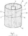
- Fig. 1 shows a catalytic chemical reactor 1, for example a reactor for the synthesis of ammonia from a synthesis gas comprising hydrogen and nitrogen.
- the reactor 1 comprises a substantially cylindrical shell 2 provided at the top end with an inlet opening 3 for reagent gases 20 and at the bottom end with an outlet opening 4 for a gaseous flow 21 comprising the reaction products.
- the reactor 1 contains a catalytic bed 5 with annular cross-section passed through by an axial-radial flow.
- Said catalytic bed 5 is delimited by an outer wall 6 in the vicinity of the shell 2 and an inner wall 7, for the inlet and outlet of the gases into/from the bed 5, respectively.
- the catalytic bed 5 is open at the top so as to allow a first portion 20a of the reagent gas flow to pass axially through it.
- the wall 6 is formed by perforated tubes 10 in a ring arrangement, for example along a circumference.
- Said tubes 10 have an open top end 11 for the entry of a second portion 20b of the gas flow 20 and a closed bottom end 12.
- the tubes 10 may be advantageously supported and kept in position by at least one ring 13 ( Fig. 2 ).
- Said ring 13 is preferably arranged at the top end of the tubes.
- Further means for supporting the tubes in some embodiments, consist of a series of supports or guides welded to the walls of the reactor 1.
- the tubes 10 comprise a plurality of holes 14 arranged uniformly along their side surface, in a respective hole arrangement, so as to supply the second gaseous portion 20b to the catalytic bed 5, with an essentially radial flow.
- Said holes 14 have dimensions such as to allow the free passage of the reagent gas, and not of the catalyst of the catalytic bed 5, through them.
- Preferably said holes are substantially circular and have a diameter of 3 mm.
- Each tube 10 is made from a perforated strip with helical or longitudinal welding.
- Fig. 3 shows a tube 10 made by helical winding of a strip 15 and subsequent helical welding 16 of the edges of the strip. The process is also referred to as "spiral welding”.
- Fig. 4 shows, instead, an embodiment of the tube 10 with a longitudinal welding 17 (simple longitudinal welding).
- both the helical weld 16 and the longitudinal weld 17 are butt welds, i.e. without edges overlapping.
- Fig. 4 in particular shows that the longitudinal weld 17 is performed without overlapping the edges 18 and 19 of the perforated strip 15.
- the holes 14 are distributed over the entire side surface of the tube 10.
- Figs. 5 and 6 show two examples of cross-sectional views of a tube 10, according to preferred embodiments, with a circular cross-section ( Fig. 5 ) and elliptical cross-section ( Fig. 6 ), respectively.
- the cross-section of the tube is symmetrical relative to two axes X, Y which are perpendicular to each other.
- said tubes 10 are commercial tubes, which are serially produced.
- Fig. 9 shows a preferred embodiment comprising a top cover 22 for the catalytic bed, which supports the tubes 10 and comprises openings 23 to allow a partially axial flow (flow 20a in Fig. 1 ).
- the outer ring 24 of said cover 22 operates substantially as a supporting and retaining ring for the tubes 10.
- the wall 6, which is substantially formed by the tubes 10 described above, has the function of both favouring a uniform distribution of the gaseous flow of reagents 20 inside the catalytic bed 5 and of containing and mechanically supporting the catalytic bed 5.
- the inner wall 7 for example is a perforated central tube with a closing cover 9 and defines a collecting chamber 8 for the reaction products.
- the arrows shown in Fig. 1 indicate the paths followed by the gases inside the reactor and in particular through the catalytic bed 5.
- the reagent gases 20 enter the catalytic bed partly (flow 20a) with an axial flow through the open top part of the bed, and partly (flow 20b) with a radial flow through the perforated tubes 10.
- the reaction products are collected inside the chamber 8, forming the output flow 21.
Landscapes
- Chemical & Material Sciences (AREA)
- Organic Chemistry (AREA)
- Chemical Kinetics & Catalysis (AREA)
- Physics & Mathematics (AREA)
- Fluid Mechanics (AREA)
- Devices And Processes Conducted In The Presence Of Fluids And Solid Particles (AREA)
- Physical Or Chemical Processes And Apparatus (AREA)
Priority Applications (11)
| Application Number | Priority Date | Filing Date | Title |
|---|---|---|---|
| EP16160701.5A EP3219384A1 (de) | 2016-03-16 | 2016-03-16 | Wände für katalysatorbetten von radial- oder axialflussreaktoren |
| CA3017633A CA3017633C (en) | 2016-03-16 | 2017-03-07 | Walls for catalytic beds of radial- or axial-radial flow reactors |
| AU2017234973A AU2017234973B2 (en) | 2016-03-16 | 2017-03-07 | Walls for catalytic beds of radial- or axial-radial flow reactors |
| EP17708287.2A EP3429737B1 (de) | 2016-03-16 | 2017-03-07 | Wände für katalysatorbetten von radial- oder axialflussreaktoren |
| CN201780017741.2A CN108778481A (zh) | 2016-03-16 | 2017-03-07 | 用于径向流反应器或轴向流反应器的催化床的壁 |
| PCT/EP2017/055239 WO2017157717A1 (en) | 2016-03-16 | 2017-03-07 | Walls for catalytic beds of radial- or axial-flow reactors |
| US16/085,116 US11369930B2 (en) | 2016-03-16 | 2017-03-07 | Walls for catalytic beds of radial- or axial-flow reactors |
| RU2018135810A RU2018135810A (ru) | 2016-03-16 | 2017-03-07 | Стенка для слоев катализатора химического реактора с радиальным или осерадиальным потоком |
| BR112018068513A BR112018068513A2 (pt) | 2016-03-16 | 2017-03-07 | paredes para leitos catalíticos de reatores de fluxo radial ou axial-radial |
| SA518392331A SA518392331B1 (ar) | 2016-03-16 | 2018-09-02 | جدران لطبقات حفزية لمفاعلات بتدفق شعاعي أو محوري شعاعي |
| CL2018002619A CL2018002619A1 (es) | 2016-03-16 | 2018-09-13 | Paredes para lechos catalíticos de reactores de flujo radial o axialmente radial. |
Applications Claiming Priority (1)
| Application Number | Priority Date | Filing Date | Title |
|---|---|---|---|
| EP16160701.5A EP3219384A1 (de) | 2016-03-16 | 2016-03-16 | Wände für katalysatorbetten von radial- oder axialflussreaktoren |
Publications (1)
| Publication Number | Publication Date |
|---|---|
| EP3219384A1 true EP3219384A1 (de) | 2017-09-20 |
Family
ID=55919577
Family Applications (2)
| Application Number | Title | Priority Date | Filing Date |
|---|---|---|---|
| EP16160701.5A Withdrawn EP3219384A1 (de) | 2016-03-16 | 2016-03-16 | Wände für katalysatorbetten von radial- oder axialflussreaktoren |
| EP17708287.2A Active EP3429737B1 (de) | 2016-03-16 | 2017-03-07 | Wände für katalysatorbetten von radial- oder axialflussreaktoren |
Family Applications After (1)
| Application Number | Title | Priority Date | Filing Date |
|---|---|---|---|
| EP17708287.2A Active EP3429737B1 (de) | 2016-03-16 | 2017-03-07 | Wände für katalysatorbetten von radial- oder axialflussreaktoren |
Country Status (10)
| Country | Link |
|---|---|
| US (1) | US11369930B2 (de) |
| EP (2) | EP3219384A1 (de) |
| CN (1) | CN108778481A (de) |
| AU (1) | AU2017234973B2 (de) |
| BR (1) | BR112018068513A2 (de) |
| CA (1) | CA3017633C (de) |
| CL (1) | CL2018002619A1 (de) |
| RU (1) | RU2018135810A (de) |
| SA (1) | SA518392331B1 (de) |
| WO (1) | WO2017157717A1 (de) |
Cited By (2)
| Publication number | Priority date | Publication date | Assignee | Title |
|---|---|---|---|---|
| WO2018210629A1 (de) * | 2017-05-17 | 2018-11-22 | Thyssenkrupp Industrial Solutions Ag | Radialstromeinsatzvorrichtung zum vorgeben wenigstens eines radialen strömungspfades in einem schüttungsreaktor sowie montageverfahren und verwendung |
| EP3572146A1 (de) * | 2018-05-25 | 2019-11-27 | Consejo Superior De Investigaciones Científicas | Reaktor zur erwärmung eines gases und verwendungen davon |
Families Citing this family (3)
| Publication number | Priority date | Publication date | Assignee | Title |
|---|---|---|---|---|
| US11207648B2 (en) * | 2020-01-30 | 2021-12-28 | Uop Llc | Slotted plate scallops |
| FR3112699B1 (fr) * | 2020-07-27 | 2023-03-03 | Ifp Energies Now | Dispositif pour la séparation radiale en lit mobile simulé |
| PE20231588A1 (es) * | 2021-02-10 | 2023-10-10 | Casale Sa | Reactor de sintesis catalitica |
Citations (9)
| Publication number | Priority date | Publication date | Assignee | Title |
|---|---|---|---|---|
| US2639224A (en) * | 1950-08-31 | 1953-05-19 | Gulf Oil Corp | Catalytic reactor |
| US2683654A (en) * | 1952-01-25 | 1954-07-13 | Universal Oil Prod Co | Internally insulated and lined reactor |
| US3314141A (en) * | 1963-07-23 | 1967-04-18 | Ct De Rech S De Pont A Mousson | Method and device for manufacturing metal tubes by helically coiling a sheet metal strip |
| US4374095A (en) * | 1981-10-29 | 1983-02-15 | Chevron Research Company | Method and apparatus for restraining radial flow catalytic reactor centerpipes |
| JPS60137431A (ja) * | 1983-12-26 | 1985-07-22 | Toyo Eng Corp | 半径流反応または吸着装置 |
| US5202097A (en) * | 1990-06-15 | 1993-04-13 | Institut Francais Du Petrole | Reactor with a lower wall and/or an upper wall having a layer of a flexible refractory material |
| US20040091404A1 (en) * | 2002-11-12 | 2004-05-13 | Ablin David W. | Apparatus and process for reacting over two catalyst beds |
| EP2014356A1 (de) | 2007-07-04 | 2009-01-14 | Ammonia Casale S.A. | Wandsystem für Katalysatorbetten von Synthese-Reaktoren und Verfahren zur Herstellung des Systems |
| US20090155144A1 (en) * | 2007-12-14 | 2009-06-18 | Fecteau David J | Fluid Distributor for Radial-Flow Reactor |
Family Cites Families (7)
| Publication number | Priority date | Publication date | Assignee | Title |
|---|---|---|---|---|
| US3293403A (en) * | 1966-04-21 | 1966-12-20 | American Mach & Foundry | Butt welding of metal members by high frequency heating current |
| JPS60137431U (ja) | 1984-02-22 | 1985-09-11 | 三菱化成ポリテック株式会社 | 電極用金属蒸着用治具 |
| CN1342513A (zh) * | 2000-09-14 | 2002-04-03 | 中国石化集团齐鲁石油化工公司 | 一种适于变换工段中净化和变换反应的反应器 |
| JP3507050B2 (ja) * | 2001-09-25 | 2004-03-15 | 住友軽金属工業株式会社 | 摩擦攪拌接合方法 |
| EP1300190A1 (de) * | 2001-10-04 | 2003-04-09 | Methanol Casale S.A. | Reaktor zur Durchführung von heterogen katalysierten Reaktionen mit modularen Katalysatorelemente |
| WO2004065763A2 (en) * | 2003-01-22 | 2004-08-05 | Vast Power Systems Inc. | Thermodynamic cycles using thermal diluent |
| EP1818094A1 (de) * | 2006-02-13 | 2007-08-15 | Ammonia Casale S.A. | Wandsystem für katalytische Betten von Synthesereaktoren |
-
2016
- 2016-03-16 EP EP16160701.5A patent/EP3219384A1/de not_active Withdrawn
-
2017
- 2017-03-07 RU RU2018135810A patent/RU2018135810A/ru not_active Application Discontinuation
- 2017-03-07 CA CA3017633A patent/CA3017633C/en active Active
- 2017-03-07 US US16/085,116 patent/US11369930B2/en active Active
- 2017-03-07 CN CN201780017741.2A patent/CN108778481A/zh active Pending
- 2017-03-07 BR BR112018068513A patent/BR112018068513A2/pt not_active Application Discontinuation
- 2017-03-07 AU AU2017234973A patent/AU2017234973B2/en not_active Ceased
- 2017-03-07 WO PCT/EP2017/055239 patent/WO2017157717A1/en not_active Ceased
- 2017-03-07 EP EP17708287.2A patent/EP3429737B1/de active Active
-
2018
- 2018-09-02 SA SA518392331A patent/SA518392331B1/ar unknown
- 2018-09-13 CL CL2018002619A patent/CL2018002619A1/es unknown
Patent Citations (9)
| Publication number | Priority date | Publication date | Assignee | Title |
|---|---|---|---|---|
| US2639224A (en) * | 1950-08-31 | 1953-05-19 | Gulf Oil Corp | Catalytic reactor |
| US2683654A (en) * | 1952-01-25 | 1954-07-13 | Universal Oil Prod Co | Internally insulated and lined reactor |
| US3314141A (en) * | 1963-07-23 | 1967-04-18 | Ct De Rech S De Pont A Mousson | Method and device for manufacturing metal tubes by helically coiling a sheet metal strip |
| US4374095A (en) * | 1981-10-29 | 1983-02-15 | Chevron Research Company | Method and apparatus for restraining radial flow catalytic reactor centerpipes |
| JPS60137431A (ja) * | 1983-12-26 | 1985-07-22 | Toyo Eng Corp | 半径流反応または吸着装置 |
| US5202097A (en) * | 1990-06-15 | 1993-04-13 | Institut Francais Du Petrole | Reactor with a lower wall and/or an upper wall having a layer of a flexible refractory material |
| US20040091404A1 (en) * | 2002-11-12 | 2004-05-13 | Ablin David W. | Apparatus and process for reacting over two catalyst beds |
| EP2014356A1 (de) | 2007-07-04 | 2009-01-14 | Ammonia Casale S.A. | Wandsystem für Katalysatorbetten von Synthese-Reaktoren und Verfahren zur Herstellung des Systems |
| US20090155144A1 (en) * | 2007-12-14 | 2009-06-18 | Fecteau David J | Fluid Distributor for Radial-Flow Reactor |
Cited By (3)
| Publication number | Priority date | Publication date | Assignee | Title |
|---|---|---|---|---|
| WO2018210629A1 (de) * | 2017-05-17 | 2018-11-22 | Thyssenkrupp Industrial Solutions Ag | Radialstromeinsatzvorrichtung zum vorgeben wenigstens eines radialen strömungspfades in einem schüttungsreaktor sowie montageverfahren und verwendung |
| EP3572146A1 (de) * | 2018-05-25 | 2019-11-27 | Consejo Superior De Investigaciones Científicas | Reaktor zur erwärmung eines gases und verwendungen davon |
| WO2019224398A1 (en) * | 2018-05-25 | 2019-11-28 | Consejo Superior De Investigaciones Científicas | Reactor for heating a gas and uses thereof |
Also Published As
| Publication number | Publication date |
|---|---|
| CN108778481A (zh) | 2018-11-09 |
| US20190076805A1 (en) | 2019-03-14 |
| US11369930B2 (en) | 2022-06-28 |
| WO2017157717A1 (en) | 2017-09-21 |
| BR112018068513A2 (pt) | 2019-01-22 |
| RU2018135810A (ru) | 2020-04-16 |
| CA3017633A1 (en) | 2017-09-21 |
| AU2017234973A1 (en) | 2018-08-30 |
| SA518392331B1 (ar) | 2022-11-17 |
| EP3429737A1 (de) | 2019-01-23 |
| CA3017633C (en) | 2023-06-27 |
| EP3429737B1 (de) | 2022-08-24 |
| AU2017234973B2 (en) | 2021-05-27 |
| CL2018002619A1 (es) | 2018-11-16 |
Similar Documents
| Publication | Publication Date | Title |
|---|---|---|
| EP3429737B1 (de) | Wände für katalysatorbetten von radial- oder axialflussreaktoren | |
| US7871579B2 (en) | Tubular reactor with expandable insert | |
| EP1993718B1 (de) | Wandsystem für katalytische betten von synthesereaktoren | |
| US10294114B2 (en) | Ammonia converter comprising a tubular inner wall | |
| JP4499970B2 (ja) | スパイラル式熱交換器 | |
| CN102046278B (zh) | 一种用于在径流式反应器中外部地保持催化剂床的系统 | |
| US10155211B2 (en) | Method for realizing internal walls of catalytic reactors | |
| CN107921396B (zh) | 管式等温催化反应器 | |
| CN211800861U (zh) | 一种多线程折流管箱及反应器 | |
| EP2244821B1 (de) | Isothermischer chemischer reaktor mit plattenwärmetauscher | |
| JPH0365238A (ja) | 反応器の槽構造 | |
| US10850245B2 (en) | Systems and methods for improving flow in radial flow reactor | |
| US20050036923A1 (en) | End cone construction for catalytic converters and method for making same | |
| EP3277418B1 (de) | Harnstoffsynthesereaktor und verfahren | |
| EP3471872B1 (de) | Verteilungskanal- stützverteiler für radialstromreaktor | |
| KR20140070456A (ko) | 튜브 번들 반응기 | |
| CN107530670A (zh) | 用于反应器的锥形管道 | |
| US10300446B2 (en) | Catalytic reactor | |
| CN112536002A (zh) | 一种用于径向移动床反应器的中心管 | |
| RU2849359C1 (ru) | Реактор каталитического синтеза | |
| CN214888815U (zh) | 一种承压容器 | |
| CN108057282B (zh) | 过滤网的制造方法 | |
| JPS59131891A (ja) | 多管式熱交換器 |
Legal Events
| Date | Code | Title | Description |
|---|---|---|---|
| PUAI | Public reference made under article 153(3) epc to a published international application that has entered the european phase |
Free format text: ORIGINAL CODE: 0009012 |
|
| AK | Designated contracting states |
Kind code of ref document: A1 Designated state(s): AL AT BE BG CH CY CZ DE DK EE ES FI FR GB GR HR HU IE IS IT LI LT LU LV MC MK MT NL NO PL PT RO RS SE SI SK SM TR |
|
| AX | Request for extension of the european patent |
Extension state: BA ME |
|
| STAA | Information on the status of an ep patent application or granted ep patent |
Free format text: STATUS: THE APPLICATION IS DEEMED TO BE WITHDRAWN |
|
| 18D | Application deemed to be withdrawn |
Effective date: 20180321 |