EP3219436B1 - Dispositif de rotation motorise d'un porte-outil fixe dans des directions de rotation opposees - Google Patents
Dispositif de rotation motorise d'un porte-outil fixe dans des directions de rotation opposees Download PDFInfo
- Publication number
- EP3219436B1 EP3219436B1 EP16000670.6A EP16000670A EP3219436B1 EP 3219436 B1 EP3219436 B1 EP 3219436B1 EP 16000670 A EP16000670 A EP 16000670A EP 3219436 B1 EP3219436 B1 EP 3219436B1
- Authority
- EP
- European Patent Office
- Prior art keywords
- assigned
- flange
- workpiece carrier
- drum drive
- shaft
- Prior art date
- Legal status (The legal status is an assumption and is not a legal conclusion. Google has not performed a legal analysis and makes no representation as to the accuracy of the status listed.)
- Not-in-force
Links
- 238000012423 maintenance Methods 0.000 claims description 11
- 238000009434 installation Methods 0.000 claims description 5
- NJPPVKZQTLUDBO-UHFFFAOYSA-N novaluron Chemical compound C1=C(Cl)C(OC(F)(F)C(OC(F)(F)F)F)=CC=C1NC(=O)NC(=O)C1=C(F)C=CC=C1F NJPPVKZQTLUDBO-UHFFFAOYSA-N 0.000 claims description 5
- 238000010276 construction Methods 0.000 claims description 4
- 238000006073 displacement reaction Methods 0.000 claims 1
- 238000003860 storage Methods 0.000 description 13
- 230000008878 coupling Effects 0.000 description 9
- 238000010168 coupling process Methods 0.000 description 9
- 238000005859 coupling reaction Methods 0.000 description 9
- 239000000969 carrier Substances 0.000 description 5
- 230000013011 mating Effects 0.000 description 3
- 229910000831 Steel Inorganic materials 0.000 description 2
- 230000005540 biological transmission Effects 0.000 description 2
- 239000002184 metal Substances 0.000 description 2
- 239000010959 steel Substances 0.000 description 2
- BSYNRYMUTXBXSQ-UHFFFAOYSA-N Aspirin Chemical compound CC(=O)OC1=CC=CC=C1C(O)=O BSYNRYMUTXBXSQ-UHFFFAOYSA-N 0.000 description 1
- 230000001133 acceleration Effects 0.000 description 1
- 239000000853 adhesive Substances 0.000 description 1
- 230000001070 adhesive effect Effects 0.000 description 1
- 230000000254 damaging effect Effects 0.000 description 1
- 238000003754 machining Methods 0.000 description 1
- 238000004519 manufacturing process Methods 0.000 description 1
- 239000000463 material Substances 0.000 description 1
- 230000000149 penetrating effect Effects 0.000 description 1
- 238000003825 pressing Methods 0.000 description 1
- 230000002441 reversible effect Effects 0.000 description 1
- 238000003466 welding Methods 0.000 description 1
Images



Classifications
-
- B—PERFORMING OPERATIONS; TRANSPORTING
- B23—MACHINE TOOLS; METAL-WORKING NOT OTHERWISE PROVIDED FOR
- B23Q—DETAILS, COMPONENTS, OR ACCESSORIES FOR MACHINE TOOLS, e.g. ARRANGEMENTS FOR COPYING OR CONTROLLING; MACHINE TOOLS IN GENERAL CHARACTERISED BY THE CONSTRUCTION OF PARTICULAR DETAILS OR COMPONENTS; COMBINATIONS OR ASSOCIATIONS OF METAL-WORKING MACHINES, NOT DIRECTED TO A PARTICULAR RESULT
- B23Q1/00—Members which are comprised in the general build-up of a form of machine, particularly relatively large fixed members
- B23Q1/25—Movable or adjustable work or tool supports
- B23Q1/44—Movable or adjustable work or tool supports using particular mechanisms
- B23Q1/50—Movable or adjustable work or tool supports using particular mechanisms with rotating pairs only, the rotating pairs being the first two elements of the mechanism
- B23Q1/52—Movable or adjustable work or tool supports using particular mechanisms with rotating pairs only, the rotating pairs being the first two elements of the mechanism a single rotating pair
- B23Q1/525—Movable or adjustable work or tool supports using particular mechanisms with rotating pairs only, the rotating pairs being the first two elements of the mechanism a single rotating pair which is parallel to the working surface
-
- B—PERFORMING OPERATIONS; TRANSPORTING
- B23—MACHINE TOOLS; METAL-WORKING NOT OTHERWISE PROVIDED FOR
- B23Q—DETAILS, COMPONENTS, OR ACCESSORIES FOR MACHINE TOOLS, e.g. ARRANGEMENTS FOR COPYING OR CONTROLLING; MACHINE TOOLS IN GENERAL CHARACTERISED BY THE CONSTRUCTION OF PARTICULAR DETAILS OR COMPONENTS; COMBINATIONS OR ASSOCIATIONS OF METAL-WORKING MACHINES, NOT DIRECTED TO A PARTICULAR RESULT
- B23Q16/00—Equipment for precise positioning of tool or work into particular locations not otherwise provided for
- B23Q16/02—Indexing equipment
- B23Q16/022—Indexing equipment in which only the indexing movement is of importance
- B23Q16/025—Indexing equipment in which only the indexing movement is of importance by converting a continuous movement into a rotary indexing movement
-
- B—PERFORMING OPERATIONS; TRANSPORTING
- B25—HAND TOOLS; PORTABLE POWER-DRIVEN TOOLS; MANIPULATORS
- B25H—WORKSHOP EQUIPMENT, e.g. FOR MARKING-OUT WORK; STORAGE MEANS FOR WORKSHOPS
- B25H1/00—Work benches; Portable stands or supports for positioning portable tools or work to be operated on thereby
- B25H1/0007—Work benches; Portable stands or supports for positioning portable tools or work to be operated on thereby for engines, motor-vehicles or bicycles
-
- B—PERFORMING OPERATIONS; TRANSPORTING
- B25—HAND TOOLS; PORTABLE POWER-DRIVEN TOOLS; MANIPULATORS
- B25H—WORKSHOP EQUIPMENT, e.g. FOR MARKING-OUT WORK; STORAGE MEANS FOR WORKSHOPS
- B25H1/00—Work benches; Portable stands or supports for positioning portable tools or work to be operated on thereby
- B25H1/14—Work benches; Portable stands or supports for positioning portable tools or work to be operated on thereby with provision for adjusting the bench top
-
- B—PERFORMING OPERATIONS; TRANSPORTING
- B25—HAND TOOLS; PORTABLE POWER-DRIVEN TOOLS; MANIPULATORS
- B25H—WORKSHOP EQUIPMENT, e.g. FOR MARKING-OUT WORK; STORAGE MEANS FOR WORKSHOPS
- B25H1/00—Work benches; Portable stands or supports for positioning portable tools or work to be operated on thereby
- B25H1/14—Work benches; Portable stands or supports for positioning portable tools or work to be operated on thereby with provision for adjusting the bench top
- B25H1/18—Work benches; Portable stands or supports for positioning portable tools or work to be operated on thereby with provision for adjusting the bench top in inclination
-
- F—MECHANICAL ENGINEERING; LIGHTING; HEATING; WEAPONS; BLASTING
- F16—ENGINEERING ELEMENTS AND UNITS; GENERAL MEASURES FOR PRODUCING AND MAINTAINING EFFECTIVE FUNCTIONING OF MACHINES OR INSTALLATIONS; THERMAL INSULATION IN GENERAL
- F16C—SHAFTS; FLEXIBLE SHAFTS; ELEMENTS OR CRANKSHAFT MECHANISMS; ROTARY BODIES OTHER THAN GEARING ELEMENTS; BEARINGS
- F16C23/00—Bearings for exclusively rotary movement adjustable for aligning or positioning
- F16C23/06—Ball or roller bearings
- F16C23/08—Ball or roller bearings self-adjusting
- F16C23/082—Ball or roller bearings self-adjusting by means of at least one substantially spherical surface
- F16C23/086—Ball or roller bearings self-adjusting by means of at least one substantially spherical surface forming a track for rolling elements
Definitions
- the invention relates to a device for motorized rotation of a rigid, frame-shaped workpiece carrier in opposite directions of rotation for arranging workpieces, for example, components for the bodywork of the automotive industry, wherein the workpiece carrier has on each end side each a flange, both flanges each associated with a storage platform are, rotatably support the workpiece carrier above the shelf and a flange on a drum drive with a horizontal axis of rotation in predetermined angular positions drivable and in these positions also durable and can be blocked to perform certain work on the arranged on the workpiece carrier workpieces.
- Such workpiece carriers may have different shapes. On the one hand, there are workpiece carriers that are rectangular in shape, frame-shaped. Other workpiece carriers have an approximately triangular or polygonal shape in cross section and also consist of frame-like structures, wherein workpieces are arranged on the workpiece carrier in different planes.
- the workpiece carriers can have considerable dimensions and weights, in particular if they serve for fastening body components.
- the workpiece carriers are usually mounted on shaft stumps in spaced storage platforms, which may for example have a distance of several meters, for example from three to six meters and more from each other. Over this length, unevenness on the bearing floor, sales movements of the storage floor or tolerance differences during installation of the device have a damaging effect on the bearings.
- the US 2,340,707 shows a device with two spaced, in the side view triangular bearing blocks, which are arranged parallel and perpendicular to a rectangular bottom frame, which is arranged on rollers on the ground floor movable.
- the side view triangular bearing blocks carry to a limited extent back and forth pivotable frame, formed of two spaced supports, which are interconnected by a flat plate in the middle, wherein the frame is swingable about pins.
- the frame is driven by a hand crank that drives a worm gear to adjust the frame around the pins to different inclinations.
- a device for stepwise turning of workpieces to be machined with a workpiece holding holding device which sits on a rotary shaft, which is associated with a stepper drive, wherein on the rotary shaft a freewheeling gear is seated, which meshes with a rack, which itself designed as a slide or connected to a sled, which is connected via a push rod with a drive, according to P 40 27 465.9, wherein the rotary shaft is associated with a locking device which determines the rotary shaft after a predetermined angular rotation.
- the GB 607,803 describes a mounting device with a pivotable by a limited amount in opposite pivot directions frame on the motor housing can be arranged. In the respective predetermined pivot position, a locking pin can be inserted into a bore of a flange to lock the relevant pivoting position of the frame.
- a flanged coupling which has a coupling axis extending radially to the disk-shaped coupling flange, one of the coupling flange in the central region axially projecting hub with a cylindrical inner surface and conical outer surface, a circumferentially arranged hub of the clamping ring with a matched to the conical outer surface of the hub conical inner surface, annular contact surfaces on the coupling flange and the clamping ring and through holes in the clamping ring penetrating, turned into threaded holes in the coupling flange, lying on the same circle clamping screws, wherein the angle between the conical outer surface of the hub or the conical inner surface of the clamping ring on the one hand and the coupling axis on the other hand 1 ° to Is 3 ° and the distance of the pitch circle of the clamping screws from the cylindrical inner surface of the hub substantially equal to the distance of the pitch circle of the cylindrical outer surface of the clamping ring and
- a clamping device for the grooveless arrangement of a hub on a shaft, with a nested pair of radially flexible wedge rings for disposition within the annular space between the hub bore and the shaft and longitudinal force elements for pressing the wedge rings into each other to thereby radially expand the one of the wedge rings and radially narrowing the other wedge ring,
- which two wedge rings is formed by an inner wedge ring having a cylindrical inner surface for capturing the shaft in narrowing and by an outer wedge ring having a cylindrical outer surface for detecting the bore surface of the hub during expansion, which inner wedge ring a outer annular surface and the outer wedge ring has an inner annular surface with mating flat-axial tapers for inserting the inner wedge ring in the outer wedge ring, wherein at least one of the mating tapered surfaces with a a stable dry sliding material is coated, which prevents contact with metal to metal, wherein the angle of the mating tapered surfaces and the friction coefficients of the annular surfaces of the wedge rings mediate self-retaining
- the invention has for its object to design a device of the presupposed type such that a possible axial offset of the two drum axes without consequences for the drum drive and thereby an accurate turning of the workpiece carrier is made possible.
- the object is achieved by a device according to claim 1.
- Drum drives have a horizontal axis of rotation and usually consist of a turntable, which is driven by a grooved roller and roller pin.
- the grooved roller gets its drive by a reversible electric motor.
- Such drives referred to as drum drives, enable extremely precise control of predetermined machining positions.
- the two flange shafts for the rotatable mounting of the workpiece carrier are mounted in pillow blocks with spherical roller bearings with permissible axial and angular misalignment for exact, stress-free construction and to compensate for any possible setting behavior of the hall floor.
- the flange rollers can have a considerable distance from the floor, for example, one or more meters above the floor, for example, 1.6 m above the floor, be arranged.
- the local flange shaft is assigned an integrated media distributor.
- the stub shafts have reinforced connecting flanges, while the drum drive is designed with a torque arm.
- the drum drive in the invention assumes no fixed bearing function.
- the connection of the drum drive in the workpiece carrier is quasi floating with the help of a torque arm.
- a possible axial offset of the two drum axes remains inconsequential for the drum drive.
- the solution according to the invention allows the use of a mounting stakeout even with disassembled drum drive.
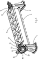
- the reference numeral 1 or 2 two mutually spaced bearing pedestals made of steel, which are connected by a steel existing profile tube 3 with each other.
- the profile tube 3 is connected via flanges 4 or 5 by means of unspecified screws in one piece with the respective storage platform 1 or 2 releasably connected.
- the profile tube 3 serves as an assembly aid and is used z. B. also for safe distance determination of the storage platforms 1, 2 from each other.
- Each storage platform 1 or 2 is supported in the illustrated embodiment, in each case via a bottom plate assembly 6 or 7 on the respective installation floor, for example, a production hall in the bodywork of the automotive industry, from releasably.
- the storage platforms 1, 2 are designed box-shaped and reinforced by transverse and longitudinal struts to increase their respective modulus.
- a frame-shaped workpiece carrier 8 in opposite directions, preferably by 360 degrees arbitrarily, in particular stepwise, rotatable, and in the respective desired angular position formed durable and lockable.
- the workpiece carrier 8 is in the illustrated embodiment in plan view rectangular shaped ( Fig. 1 ) and formed torsionally stiff over transverse and longitudinal ribs.
- suitable workpieces in particular sheets or body parts in the bodywork of the automotive industry, can be arranged, which are rotatable in any angular positions through the workpiece carrier 8 to work on them suitable, for example, welding or adhesive work, preferably by multi-axis robot (not shown).
- the workpiece carrier 8 is rotatably mounted via flange shafts 9, 10.
- the workpiece carrier 8 is assigned to each end face in each case a flange 11 and 12, which is connected to the workpiece carrier 8 by means of a gear.
- the flange 11 or 12 is associated with a flange 13 or 14 of the flange shaft 9 and 10, respectively.
- the respective opposing flanges 11, 13 and 12, 14 are geared, in particular by screw, releasably coupled together.
- the flange 13 is operatively connected to the flange shaft 9 and the flange 14 with the flange shaft 10th
- the stub shafts 9 and 10 are each mounted in a pillow block bearing with spherical roller bearings 15 and 16 respectively.
- the spherical roller bearings 15, 16 may be formed both with permissible axial and angular misalignment for exact, tension-free construction and to compensate for any setting behavior of the hall floor, if necessary, but one will preferably form one of the spherical roller bearings 15 or 16 as Axialfestlager, preferably on the part of the rotary drive ,
- an integrated rotary distributor for example a Rekofa rotary distributor, is arranged.
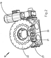
- the flange shaft 9 is driven by a drum drive 18, which is associated with an electric motor, in particular an asynchronous motor 19.
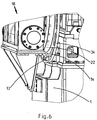
- the electric motor 19 is designed as a servomotor with a multi-turn absolute value transmitter, which can be driven by a slot shaft 20 (FIG. Fig. 2 ), which is drivable in opposite directions by the motor 19 and which drives a turntable 22 via a precision roller pin 21 via a horizontal and coaxial with the flange shaft 9 arranged axis of rotation. This results in a precise positioning by low-play, torsionally rigid transmission elements, a flat roll pitch and bias the tabletop. There is no additional position stakeout required, resulting in no cycle time loss.
- the camshaft 20 associated curve is determined mathematically depending on the operating conditions. It may also be a grooved roll or a web roll or a globoid roll act. The shape and slope of the curve can map the speed and acceleration profile and, if necessary, detect latching passages in which the groove of the groove shaft 20 has no slope. In general, a plurality of roller pins 21 will be in engagement with the groove of the groove shaft 20, whereby a multiple torque transmission is given in both directions of rotation.
- flange shaft 9 designed as Abzusflansch drive flange 23 arranged by gearing.
- the attachment to the flange shaft 9 is - as out Fig. 8 can be seen - achieved by wedge rings 24, 25, which form a clamping connection, which are directed with their wedge-length portion against each other and which are distributed over numerous evenly spaced over the circumference of the clamping connections 24, 25 distributed screws 26 in the axial direction against each other, whereby the Clamping 24 and 25 large axially and radially directed forces in the hub of the drive flange 23 on the one hand and against the circumference of the stub shaft 9 on the other hand, so that the drive flange 23 frictionally functionally in one piece on the flange shaft 9, but releasably disposed.
- the clamp connection 24, 25 is self-centering.
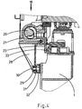
- the housing 27 of the drum drive 18 is integrally associated with a projection 28, which has a bearing 29 a z. B. designed as a ball bearing space-hinged bearing 30 receives.
- a torque arm 31 which is associated with the storage platform 1 and with a lug 32 with this in one piece, but releasably connected.
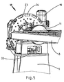
- the reference numeral 33 denotes an integrated maintenance stake out, which in Fig. 4 and 6 is shown in the extended state.
- the maintenance stakeout 33 is driven by a motor, for example by an alternately acted upon by compressed air on both sides piston-cylinder unit and includes, for example, a plurality of bolts in recesses 34 of the drive flange 23 of the drum drive 18 z. B. positively engage and thereby block the drive flange 23 securely.
- the maintenance stakeout 33 is assigned in the storage platform 1, namely on the workpiece carrier side. This results in a space-saving, modular design with integrated maintenance stakeout.
- the drum drive 18 is raised separately and can be replaced separately and / or serviced.
Landscapes
- Engineering & Computer Science (AREA)
- Mechanical Engineering (AREA)
- Rolls And Other Rotary Bodies (AREA)
Claims (3)
- Dispositif de rotation motorisée d'un porte-pièces (8) rigide en forme de cadre dans des directions opposées, servant à disposer des pièces à usiner, par exemple des composants destinées à la construction de carrosseries automobiles, sachant que le porte-pièces à usiner (8) présente sur chaque côté frontal un arbre à bride (9 ou 10), sachant que les deux arbres à bride (9 et 10) sont affectés chacun à un piètement palier (1 ou 2) qui reçoivent en appui tournant le porte-pièces à usiner (8) au-dessus du sol, et qu'un arbre à bride (9) peut être entraîné via un entraînement à tambour (18) à axe de rotation horizontal pour atteindre par rotation des positions angulaires prédéfinies et qu'il peut également être arrêté et bloqué dans ces positions pour pouvoir réaliser des travaux précis sur les pièces à usiner disposées sur le porte-pièces à usiner (8), sachant qu'à l'entraînement à tambour (18) est affecté un moteur électrique, en particulier un moteur asynchrone (19) auquel est affecté un arbre à gorge (20) qui peut être entraîné dans des directions opposées par le moteur électrique (19), et qui via un goujon (21) à rouleaux de précision entraîne un plateau tournant (22) via un axe de rotation disposé horizontalement et coaxialement à l'arbre à bride (9), sachant que l'arbre à bride (9) affecté à l'entraînement à tambour (18) ou les deux arbres à bride (9 et 10) sont en appui dans des paliers verticaux équipés de roulements à rotules (15, 16) pour obtenir un déport axial et angulaire admissible afin d'obtenir un montage précis et exempt de tensions mécaniques, et pour compenser une éventuelle réaction de tassement du sol, sachant qu'est attribuée - de façon monobloc au plan fonctionnel ou matériel - au carter (27) de l'entraînement (18) de tambour, une équerre (28) configurée en bras de réaction qui prend appui de manière mobile articulée dans l'espace, en particulier via une articulation spatiale configurée en roulement à billes (30), contre un bras de réaction (31) affecté monobloc au piètement palier (1), et sachant qu'à l'arbre à bride (9) attribué à l'entraînement (18) de tambour sur montants à part est affectée par transmission une bride d'entraînement (23), bride qui présente sur sa circonférence plusieurs perforations ou évidements (34) avec lesquels interagit par adhérence de formes ou de forces un dispositif de délimitation (33) motorisé utilisé pour la maintenance, sachant que le dispositif de délimitation (33) pour la maintenance est affecté au piètement palier (1).
- Dispositif selon la revendication 1, caractérisé en ce que le dispositif de délimitation (33) pour la maintenance se compose d'un ou plusieurs goujons (31) de retenue pouvant rentrer et sortir dans des directions opposées, qui engrène ou engrènent par adhérence de forces et/ou de formes dans un ou plusieurs évidement(s) (34) de la bride d'entraînement (23) lorsqu'il(s) se trouve(nt) en position sortie, c'est-à-dire en position de délimitation pour la maintenance.
- Dispositif selon la revendication 1 ou 2, caractérisé en ce que la bride d'entraînement (23) est disposée par adhérence de forces sur l'arbre à brides (9) via un dispositif de bridage (24, 25) autocentré.
Priority Applications (1)
| Application Number | Priority Date | Filing Date | Title |
|---|---|---|---|
| EP16000670.6A EP3219436B1 (fr) | 2016-03-19 | 2016-03-19 | Dispositif de rotation motorise d'un porte-outil fixe dans des directions de rotation opposees |
Applications Claiming Priority (1)
| Application Number | Priority Date | Filing Date | Title |
|---|---|---|---|
| EP16000670.6A EP3219436B1 (fr) | 2016-03-19 | 2016-03-19 | Dispositif de rotation motorise d'un porte-outil fixe dans des directions de rotation opposees |
Publications (2)
| Publication Number | Publication Date |
|---|---|
| EP3219436A1 EP3219436A1 (fr) | 2017-09-20 |
| EP3219436B1 true EP3219436B1 (fr) | 2018-11-07 |
Family
ID=55646210
Family Applications (1)
| Application Number | Title | Priority Date | Filing Date |
|---|---|---|---|
| EP16000670.6A Not-in-force EP3219436B1 (fr) | 2016-03-19 | 2016-03-19 | Dispositif de rotation motorise d'un porte-outil fixe dans des directions de rotation opposees |
Country Status (1)
| Country | Link |
|---|---|
| EP (1) | EP3219436B1 (fr) |
Cited By (1)
| Publication number | Priority date | Publication date | Assignee | Title |
|---|---|---|---|---|
| WO2026039851A1 (fr) * | 2024-08-19 | 2026-02-26 | Facc Ag | Dispositif de montage |
Families Citing this family (8)
| Publication number | Priority date | Publication date | Assignee | Title |
|---|---|---|---|---|
| PT110317A (pt) * | 2017-09-29 | 2019-03-29 | Mbm Evo Lda | Bancada rotativa |
| CN109454379B (zh) * | 2018-10-31 | 2021-02-02 | 中车长江车辆有限公司 | 一种悬挂式单轨墩柱翻转焊接装置 |
| DE102018131796B4 (de) * | 2018-12-11 | 2023-04-20 | Taktomat Kurvengesteuerte Antriebssysteme Gmbh | Drehvorrichtung |
| FR3092076B1 (fr) * | 2019-01-25 | 2020-12-25 | Psa Automobiles Sa | Berceau pour une ligne robotisée d’assemblage de pièces de carrosserie |
| CN109759995A (zh) * | 2019-02-28 | 2019-05-17 | 深圳市宝盛自动化设备有限公司 | 一种大尺寸翻转机构 |
| CN111546304B (zh) * | 2020-04-22 | 2022-07-12 | 天津大学 | 一种单电机输入三自由度转动机构 |
| US12162097B2 (en) | 2021-01-28 | 2024-12-10 | Yaskawa America, Inc. | Workpiece positioner assembly having compliance assemblies |
| CN116423123A (zh) * | 2023-03-27 | 2023-07-14 | 湖南坤鼎数控科技有限公司 | 一种自行走高空作业平台后支腿铆焊工装 |
Family Cites Families (33)
| Publication number | Priority date | Publication date | Assignee | Title |
|---|---|---|---|---|
| US2340707A (en) * | 1941-11-17 | 1944-02-01 | Joseph H Staley | Shop engine stand revolving means |
| GB607803A (en) * | 1946-02-12 | 1948-09-06 | Sykes & Robinson Ltd | Improvements in or relating to engine mounting fixtures |
| DE1846776U (de) | 1961-12-21 | 1962-02-15 | Walther Dipl Ing Zarges | Vorrichtung zum parallelfuehren einer heb- und senkbaren plattform, insbesondere des hoehenbewegbaren bodens eines behaelters. |
| US3741512A (en) | 1971-11-04 | 1973-06-26 | Amf Inc | Self-leveling dispenser |
| US4093199A (en) * | 1977-08-02 | 1978-06-06 | Ralph Stewart | Rotatable engine supporting apparatus |
| US4367053A (en) * | 1978-11-06 | 1983-01-04 | Andrew Stratienko | Clamping device |
| DE3000667A1 (de) | 1980-01-10 | 1981-07-16 | Lupo, geb. Brockerhoff, Marianne, 6900 Heidelberg | Hubeinrichtung fuer fernsehtruhen o.dgl. |
| JPS6031427A (ja) | 1983-07-29 | 1985-02-18 | Yoshio Daiki | 直進間欠移送装置 |
| US4764075A (en) | 1986-04-22 | 1988-08-16 | Safetech Pty. Ltd. | Load elevator |
| DE3639216A1 (de) | 1986-11-15 | 1988-05-19 | Eisenberg Hans Jochen | Von hand hoehenverstellbarer podestbock |
| NL8800835A (nl) | 1988-03-31 | 1989-10-16 | Brinkers Gerardus Cornelis | Verplaatsbare draag- en hefinrichting voor het ondersteunen van een plateau. |
| DE4118305A1 (de) * | 1990-08-30 | 1992-12-10 | Heinz Schaefer | Vorrichtung zum schrittweisen drehen von zu bearbeitenden werkstuecken |
| JPH0749927A (ja) | 1993-08-09 | 1995-02-21 | Nireco Corp | パターン認識方法 |
| DE4345090C2 (de) | 1993-12-31 | 1995-11-23 | Perthen Feinpruef Gmbh | Drehtisch |
| DE9412971U1 (de) | 1994-08-11 | 1994-12-15 | Expert Maschinenbau Gmbh, 64653 Lorsch | Hubtisch |
| DE19512363C2 (de) * | 1995-04-01 | 1999-01-07 | Hartwig Dipl Ing Stuewe | Flanschkupplung |
| DE19837212A1 (de) | 1998-08-17 | 2000-02-24 | Itec Ges Fuer Prozesautomation | Stellvorrichtung |
| JP2002068681A (ja) | 2000-08-28 | 2002-03-08 | Noritake Co Ltd | 搬送装置 |
| DE10137617C2 (de) | 2001-08-01 | 2003-05-28 | Siemens Ag | Verfahren zur Inbetriebnahme einer Positioniereinrichtung |
| DE10162178A1 (de) | 2001-12-18 | 2003-07-03 | Abb Patent Gmbh | Hebevorrichtung zum Bewegen von Lasten |
| DE10217064B4 (de) | 2002-04-17 | 2005-02-17 | Maha Maschinenbau Haldenwang Gmbh & Co. Kg | Säulenhebebühne |
| JP4538212B2 (ja) | 2002-10-24 | 2010-09-08 | 株式会社三共製作所 | 駆動機構およびこれを用いた移動テーブル |
| US7434491B1 (en) * | 2003-01-10 | 2008-10-14 | Motoman, Inc. | Flexible tooling interface for headstock/tailstock positioner |
| DE102004038502A1 (de) * | 2004-08-07 | 2006-02-23 | Zf Friedrichshafen Ag | Getriebe, insbesondere zum Antrieb einer Trommel eines Fahrmischers |
| JP4700944B2 (ja) | 2004-09-08 | 2011-06-15 | 株式会社三共製作所 | 駆動機構及びこれを用いた移動テーブル |
| DE102005038663A1 (de) | 2005-08-16 | 2007-02-22 | Weiss Gmbh Sondermaschinentechnik | Rundschalttisch |
| DE202006009312U1 (de) | 2006-06-12 | 2007-10-25 | Kuka Schweissanlagen Gmbh | Bearbeitungsstation, insbesondere Fügestation |
| DE102007021681C5 (de) | 2007-05-09 | 2011-04-21 | Tünkers Maschinenbau Gmbh | Schrittschaltdrehtisch |
| EP2093642B1 (fr) * | 2008-02-25 | 2012-02-08 | TÜNKERS MASCHINENBAU GmbH | Table rotative avec une unité de contrôle ou regulation associée |
| JP5255906B2 (ja) | 2008-05-23 | 2013-08-07 | 本田技研工業株式会社 | 車体に対する足回り部品の同期搬送装置及び同期搬送方法 |
| US8596627B2 (en) * | 2009-11-02 | 2013-12-03 | Wurk Metal Products, Inc. | Automobile rotisserie |
| US20110309228A1 (en) | 2010-06-17 | 2011-12-22 | Trinity, Llc | Product-Lifting Display and Merchandising System |
| CN103209919B (zh) | 2010-08-06 | 2016-06-15 | 科尔伊埃莱瓦托株式会社 | 一种升降装置及电梯系统 |
-
2016
- 2016-03-19 EP EP16000670.6A patent/EP3219436B1/fr not_active Not-in-force
Non-Patent Citations (1)
| Title |
|---|
| None * |
Cited By (1)
| Publication number | Priority date | Publication date | Assignee | Title |
|---|---|---|---|---|
| WO2026039851A1 (fr) * | 2024-08-19 | 2026-02-26 | Facc Ag | Dispositif de montage |
Also Published As
| Publication number | Publication date |
|---|---|
| EP3219436A1 (fr) | 2017-09-20 |
Similar Documents
| Publication | Publication Date | Title |
|---|---|---|
| EP3219436B1 (fr) | Dispositif de rotation motorise d'un porte-outil fixe dans des directions de rotation opposees | |
| DE102013012765B4 (de) | Spindeleinheit für eine Bearbeitungseinrichtung mit einer Spindelarretierung | |
| EP0205047B1 (fr) | Dispositif pivotant | |
| DE69807346T2 (de) | Halteranordnung für automobilkarosserieteile | |
| EP3310528B1 (fr) | Machine-outil pour l'usinage d'une pièce par enlèvement de copeaux | |
| EP3174488B1 (fr) | Douille, bras de support et système de support pour un socle médical | |
| WO2016091389A1 (fr) | Dispositif permettant de réaliser des travaux de soudure | |
| DE4339754C1 (de) | Vorrichtung zum Einbringen von Bohrungen in eine Schüssel bzw. eine Felge eines Kraftfahrzeug-Rades | |
| DE4032881A1 (de) | Verfahren und vorrichtung zum einspannen eines werkstuecks | |
| DE19980562B4 (de) | Glättmaschine | |
| DE2835693A1 (de) | Drehbare werkstueckhalterung, insbesondere fuer messmaschinen | |
| WO2018234193A1 (fr) | Broche de travail comprenant un dispositif de serrage radial | |
| DE102019106088A1 (de) | Klemmsystem für eine Werkzeugmaschine | |
| WO2011124458A1 (fr) | Outil motorisé portable pourvu d'un dispositif de compensation de déséquilibre et d'un dispositif de serrage pour un moyen de travail à symétrie de rotation | |
| DE3814189C2 (fr) | ||
| EP2415555A1 (fr) | Dispositif de serrage de boîtiers | |
| DE4207982C2 (de) | Einrichtung zum Halten einer Fahrzeugfelge | |
| DE202011103051U1 (de) | Hub-Drehvorrichtung, insbesondere zur Verwendung im Karosseriebau der Kfz-Industrie | |
| DE2757740B1 (de) | Abstuetzung eines Werkstuecktisches einer Zahnradpruefmaschine | |
| EP3620261A1 (fr) | Tête de broche pour une machine-outil | |
| EP3664998A1 (fr) | Presse | |
| EP1364754A2 (fr) | Dispositif de stockage d'outil, dispositif de changement d'outil et palier | |
| DE2916891C2 (de) | Einrichtung zum drehbaren Lagern eines Schraubstocks auf einer Werkbank o.dgl. | |
| DE3511040C1 (de) | Haltevorrichtung fuer Schrauben beim Messen und Pruefen der Koaxialitaet von Gewinde und Schaft bzw. beim Bearbeiten | |
| DD253544A3 (de) | Vorrichtung zum automatischen mehrfachanziehen und loesen von schraubverbindungen an apparate- oder behaelterflanschen |
Legal Events
| Date | Code | Title | Description |
|---|---|---|---|
| STAA | Information on the status of an ep patent application or granted ep patent |
Free format text: STATUS: EXAMINATION IS IN PROGRESS |
|
| PUAI | Public reference made under article 153(3) epc to a published international application that has entered the european phase |
Free format text: ORIGINAL CODE: 0009012 |
|
| 17P | Request for examination filed |
Effective date: 20160331 |
|
| AK | Designated contracting states |
Kind code of ref document: A1 Designated state(s): AL AT BE BG CH CY CZ DE DK EE ES FI FR GB GR HR HU IE IS IT LI LT LU LV MC MK MT NL NO PL PT RO RS SE SI SK SM TR |
|
| AX | Request for extension of the european patent |
Extension state: BA ME |
|
| GRAP | Despatch of communication of intention to grant a patent |
Free format text: ORIGINAL CODE: EPIDOSNIGR1 |
|
| STAA | Information on the status of an ep patent application or granted ep patent |
Free format text: STATUS: GRANT OF PATENT IS INTENDED |
|
| INTG | Intention to grant announced |
Effective date: 20180816 |
|
| GRAS | Grant fee paid |
Free format text: ORIGINAL CODE: EPIDOSNIGR3 |
|
| GRAA | (expected) grant |
Free format text: ORIGINAL CODE: 0009210 |
|
| STAA | Information on the status of an ep patent application or granted ep patent |
Free format text: STATUS: THE PATENT HAS BEEN GRANTED |
|
| AK | Designated contracting states |
Kind code of ref document: B1 Designated state(s): AL AT BE BG CH CY CZ DE DK EE ES FI FR GB GR HR HU IE IS IT LI LT LU LV MC MK MT NL NO PL PT RO RS SE SI SK SM TR |
|
| REG | Reference to a national code |
Ref country code: GB Ref legal event code: FG4D Free format text: NOT ENGLISH |
|
| REG | Reference to a national code |
Ref country code: CH Ref legal event code: EP Ref country code: AT Ref legal event code: REF Ref document number: 1061493 Country of ref document: AT Kind code of ref document: T Effective date: 20181115 |
|
| REG | Reference to a national code |
Ref country code: DE Ref legal event code: R096 Ref document number: 502016002396 Country of ref document: DE |
|
| REG | Reference to a national code |
Ref country code: IE Ref legal event code: FG4D Free format text: LANGUAGE OF EP DOCUMENT: GERMAN |
|
| REG | Reference to a national code |
Ref country code: NL Ref legal event code: MP Effective date: 20181107 |
|
| REG | Reference to a national code |
Ref country code: LT Ref legal event code: MG4D |
|
| PG25 | Lapsed in a contracting state [announced via postgrant information from national office to epo] |
Ref country code: FI Free format text: LAPSE BECAUSE OF FAILURE TO SUBMIT A TRANSLATION OF THE DESCRIPTION OR TO PAY THE FEE WITHIN THE PRESCRIBED TIME-LIMIT Effective date: 20181107 Ref country code: BG Free format text: LAPSE BECAUSE OF FAILURE TO SUBMIT A TRANSLATION OF THE DESCRIPTION OR TO PAY THE FEE WITHIN THE PRESCRIBED TIME-LIMIT Effective date: 20190207 Ref country code: HR Free format text: LAPSE BECAUSE OF FAILURE TO SUBMIT A TRANSLATION OF THE DESCRIPTION OR TO PAY THE FEE WITHIN THE PRESCRIBED TIME-LIMIT Effective date: 20181107 Ref country code: NO Free format text: LAPSE BECAUSE OF FAILURE TO SUBMIT A TRANSLATION OF THE DESCRIPTION OR TO PAY THE FEE WITHIN THE PRESCRIBED TIME-LIMIT Effective date: 20190207 Ref country code: LT Free format text: LAPSE BECAUSE OF FAILURE TO SUBMIT A TRANSLATION OF THE DESCRIPTION OR TO PAY THE FEE WITHIN THE PRESCRIBED TIME-LIMIT Effective date: 20181107 Ref country code: IS Free format text: LAPSE BECAUSE OF FAILURE TO SUBMIT A TRANSLATION OF THE DESCRIPTION OR TO PAY THE FEE WITHIN THE PRESCRIBED TIME-LIMIT Effective date: 20190307 Ref country code: ES Free format text: LAPSE BECAUSE OF FAILURE TO SUBMIT A TRANSLATION OF THE DESCRIPTION OR TO PAY THE FEE WITHIN THE PRESCRIBED TIME-LIMIT Effective date: 20181107 Ref country code: LV Free format text: LAPSE BECAUSE OF FAILURE TO SUBMIT A TRANSLATION OF THE DESCRIPTION OR TO PAY THE FEE WITHIN THE PRESCRIBED TIME-LIMIT Effective date: 20181107 |
|
| PG25 | Lapsed in a contracting state [announced via postgrant information from national office to epo] |
Ref country code: SE Free format text: LAPSE BECAUSE OF FAILURE TO SUBMIT A TRANSLATION OF THE DESCRIPTION OR TO PAY THE FEE WITHIN THE PRESCRIBED TIME-LIMIT Effective date: 20181107 Ref country code: AL Free format text: LAPSE BECAUSE OF FAILURE TO SUBMIT A TRANSLATION OF THE DESCRIPTION OR TO PAY THE FEE WITHIN THE PRESCRIBED TIME-LIMIT Effective date: 20181107 Ref country code: RS Free format text: LAPSE BECAUSE OF FAILURE TO SUBMIT A TRANSLATION OF THE DESCRIPTION OR TO PAY THE FEE WITHIN THE PRESCRIBED TIME-LIMIT Effective date: 20181107 Ref country code: GR Free format text: LAPSE BECAUSE OF FAILURE TO SUBMIT A TRANSLATION OF THE DESCRIPTION OR TO PAY THE FEE WITHIN THE PRESCRIBED TIME-LIMIT Effective date: 20190208 Ref country code: PT Free format text: LAPSE BECAUSE OF FAILURE TO SUBMIT A TRANSLATION OF THE DESCRIPTION OR TO PAY THE FEE WITHIN THE PRESCRIBED TIME-LIMIT Effective date: 20190307 Ref country code: NL Free format text: LAPSE BECAUSE OF FAILURE TO SUBMIT A TRANSLATION OF THE DESCRIPTION OR TO PAY THE FEE WITHIN THE PRESCRIBED TIME-LIMIT Effective date: 20181107 |
|
| PG25 | Lapsed in a contracting state [announced via postgrant information from national office to epo] |
Ref country code: IT Free format text: LAPSE BECAUSE OF FAILURE TO SUBMIT A TRANSLATION OF THE DESCRIPTION OR TO PAY THE FEE WITHIN THE PRESCRIBED TIME-LIMIT Effective date: 20181107 Ref country code: PL Free format text: LAPSE BECAUSE OF FAILURE TO SUBMIT A TRANSLATION OF THE DESCRIPTION OR TO PAY THE FEE WITHIN THE PRESCRIBED TIME-LIMIT Effective date: 20181107 Ref country code: DK Free format text: LAPSE BECAUSE OF FAILURE TO SUBMIT A TRANSLATION OF THE DESCRIPTION OR TO PAY THE FEE WITHIN THE PRESCRIBED TIME-LIMIT Effective date: 20181107 Ref country code: CZ Free format text: LAPSE BECAUSE OF FAILURE TO SUBMIT A TRANSLATION OF THE DESCRIPTION OR TO PAY THE FEE WITHIN THE PRESCRIBED TIME-LIMIT Effective date: 20181107 |
|
| REG | Reference to a national code |
Ref country code: DE Ref legal event code: R097 Ref document number: 502016002396 Country of ref document: DE |
|
| PG25 | Lapsed in a contracting state [announced via postgrant information from national office to epo] |
Ref country code: RO Free format text: LAPSE BECAUSE OF FAILURE TO SUBMIT A TRANSLATION OF THE DESCRIPTION OR TO PAY THE FEE WITHIN THE PRESCRIBED TIME-LIMIT Effective date: 20181107 Ref country code: SK Free format text: LAPSE BECAUSE OF FAILURE TO SUBMIT A TRANSLATION OF THE DESCRIPTION OR TO PAY THE FEE WITHIN THE PRESCRIBED TIME-LIMIT Effective date: 20181107 Ref country code: EE Free format text: LAPSE BECAUSE OF FAILURE TO SUBMIT A TRANSLATION OF THE DESCRIPTION OR TO PAY THE FEE WITHIN THE PRESCRIBED TIME-LIMIT Effective date: 20181107 Ref country code: SM Free format text: LAPSE BECAUSE OF FAILURE TO SUBMIT A TRANSLATION OF THE DESCRIPTION OR TO PAY THE FEE WITHIN THE PRESCRIBED TIME-LIMIT Effective date: 20181107 |
|
| PLBE | No opposition filed within time limit |
Free format text: ORIGINAL CODE: 0009261 |
|
| STAA | Information on the status of an ep patent application or granted ep patent |
Free format text: STATUS: NO OPPOSITION FILED WITHIN TIME LIMIT |
|
| 26N | No opposition filed |
Effective date: 20190808 |
|
| PG25 | Lapsed in a contracting state [announced via postgrant information from national office to epo] |
Ref country code: SI Free format text: LAPSE BECAUSE OF FAILURE TO SUBMIT A TRANSLATION OF THE DESCRIPTION OR TO PAY THE FEE WITHIN THE PRESCRIBED TIME-LIMIT Effective date: 20181107 Ref country code: MC Free format text: LAPSE BECAUSE OF FAILURE TO SUBMIT A TRANSLATION OF THE DESCRIPTION OR TO PAY THE FEE WITHIN THE PRESCRIBED TIME-LIMIT Effective date: 20181107 |
|
| REG | Reference to a national code |
Ref country code: CH Ref legal event code: PL |
|
| PG25 | Lapsed in a contracting state [announced via postgrant information from national office to epo] |
Ref country code: LU Free format text: LAPSE BECAUSE OF NON-PAYMENT OF DUE FEES Effective date: 20190319 |
|
| REG | Reference to a national code |
Ref country code: BE Ref legal event code: MM Effective date: 20190331 |
|
| PG25 | Lapsed in a contracting state [announced via postgrant information from national office to epo] |
Ref country code: CH Free format text: LAPSE BECAUSE OF NON-PAYMENT OF DUE FEES Effective date: 20190331 Ref country code: IE Free format text: LAPSE BECAUSE OF NON-PAYMENT OF DUE FEES Effective date: 20190319 Ref country code: LI Free format text: LAPSE BECAUSE OF NON-PAYMENT OF DUE FEES Effective date: 20190331 |
|
| PG25 | Lapsed in a contracting state [announced via postgrant information from national office to epo] |
Ref country code: FR Free format text: LAPSE BECAUSE OF NON-PAYMENT OF DUE FEES Effective date: 20190331 Ref country code: BE Free format text: LAPSE BECAUSE OF NON-PAYMENT OF DUE FEES Effective date: 20190331 |
|
| PG25 | Lapsed in a contracting state [announced via postgrant information from national office to epo] |
Ref country code: TR Free format text: LAPSE BECAUSE OF FAILURE TO SUBMIT A TRANSLATION OF THE DESCRIPTION OR TO PAY THE FEE WITHIN THE PRESCRIBED TIME-LIMIT Effective date: 20181107 |
|
| PG25 | Lapsed in a contracting state [announced via postgrant information from national office to epo] |
Ref country code: MT Free format text: LAPSE BECAUSE OF FAILURE TO SUBMIT A TRANSLATION OF THE DESCRIPTION OR TO PAY THE FEE WITHIN THE PRESCRIBED TIME-LIMIT Effective date: 20181107 |
|
| GBPC | Gb: european patent ceased through non-payment of renewal fee |
Effective date: 20200319 |
|
| PG25 | Lapsed in a contracting state [announced via postgrant information from national office to epo] |
Ref country code: GB Free format text: LAPSE BECAUSE OF NON-PAYMENT OF DUE FEES Effective date: 20200319 |
|
| PG25 | Lapsed in a contracting state [announced via postgrant information from national office to epo] |
Ref country code: CY Free format text: LAPSE BECAUSE OF FAILURE TO SUBMIT A TRANSLATION OF THE DESCRIPTION OR TO PAY THE FEE WITHIN THE PRESCRIBED TIME-LIMIT Effective date: 20181107 |
|
| PGFP | Annual fee paid to national office [announced via postgrant information from national office to epo] |
Ref country code: DE Payment date: 20210310 Year of fee payment: 6 |
|
| PG25 | Lapsed in a contracting state [announced via postgrant information from national office to epo] |
Ref country code: HU Free format text: LAPSE BECAUSE OF FAILURE TO SUBMIT A TRANSLATION OF THE DESCRIPTION OR TO PAY THE FEE WITHIN THE PRESCRIBED TIME-LIMIT; INVALID AB INITIO Effective date: 20160319 |
|
| REG | Reference to a national code |
Ref country code: AT Ref legal event code: MM01 Ref document number: 1061493 Country of ref document: AT Kind code of ref document: T Effective date: 20210319 |
|
| PG25 | Lapsed in a contracting state [announced via postgrant information from national office to epo] |
Ref country code: MK Free format text: LAPSE BECAUSE OF FAILURE TO SUBMIT A TRANSLATION OF THE DESCRIPTION OR TO PAY THE FEE WITHIN THE PRESCRIBED TIME-LIMIT Effective date: 20181107 |
|
| PG25 | Lapsed in a contracting state [announced via postgrant information from national office to epo] |
Ref country code: AT Free format text: LAPSE BECAUSE OF NON-PAYMENT OF DUE FEES Effective date: 20210319 |
|
| REG | Reference to a national code |
Ref country code: DE Ref legal event code: R119 Ref document number: 502016002396 Country of ref document: DE |
|
| PG25 | Lapsed in a contracting state [announced via postgrant information from national office to epo] |
Ref country code: DE Free format text: LAPSE BECAUSE OF NON-PAYMENT OF DUE FEES Effective date: 20221001 |