EP3219444B1 - Outil de compression - Google Patents
Outil de compression Download PDFInfo
- Publication number
- EP3219444B1 EP3219444B1 EP17165768.7A EP17165768A EP3219444B1 EP 3219444 B1 EP3219444 B1 EP 3219444B1 EP 17165768 A EP17165768 A EP 17165768A EP 3219444 B1 EP3219444 B1 EP 3219444B1
- Authority
- EP
- European Patent Office
- Prior art keywords
- lever
- compression
- pressing tool
- spindle
- tool according
- Prior art date
- Legal status (The legal status is an assumption and is not a legal conclusion. Google has not performed a legal analysis and makes no representation as to the accuracy of the status listed.)
- Active
Links
Images







Classifications
-
- B—PERFORMING OPERATIONS; TRANSPORTING
- B25—HAND TOOLS; PORTABLE POWER-DRIVEN TOOLS; MANIPULATORS
- B25B—TOOLS OR BENCH DEVICES NOT OTHERWISE PROVIDED FOR, FOR FASTENING, CONNECTING, DISENGAGING, OR HOLDING
- B25B7/00—Pliers; Other hand-held gripping tools with jaws on pivoted limbs; Details applicable generally to pivoted-limb hand tools
- B25B7/12—Pliers; Other hand-held gripping tools with jaws on pivoted limbs; Details applicable generally to pivoted-limb hand tools involving special transmission means between the handles and the jaws, e.g. toggle levers, gears
-
- B—PERFORMING OPERATIONS; TRANSPORTING
- B25—HAND TOOLS; PORTABLE POWER-DRIVEN TOOLS; MANIPULATORS
- B25B—TOOLS OR BENCH DEVICES NOT OTHERWISE PROVIDED FOR, FOR FASTENING, CONNECTING, DISENGAGING, OR HOLDING
- B25B28/00—Portable power-driven joining or separation tools
-
- B—PERFORMING OPERATIONS; TRANSPORTING
- B26—HAND CUTTING TOOLS; CUTTING; SEVERING
- B26B—HAND-HELD CUTTING TOOLS NOT OTHERWISE PROVIDED FOR
- B26B15/00—Hand-held shears with motor-driven blades
-
- B—PERFORMING OPERATIONS; TRANSPORTING
- B23—MACHINE TOOLS; METAL-WORKING NOT OTHERWISE PROVIDED FOR
- B23D—PLANING; SLOTTING; SHEARING; BROACHING; SAWING; FILING; SCRAPING; LIKE OPERATIONS FOR WORKING METAL BY REMOVING MATERIAL, NOT OTHERWISE PROVIDED FOR
- B23D17/00—Shearing machines or shearing devices cutting by blades pivoted on a single axis
- B23D17/02—Shearing machines or shearing devices cutting by blades pivoted on a single axis characterised by drives or gearings therefor
-
- B—PERFORMING OPERATIONS; TRANSPORTING
- B25—HAND TOOLS; PORTABLE POWER-DRIVEN TOOLS; MANIPULATORS
- B25B—TOOLS OR BENCH DEVICES NOT OTHERWISE PROVIDED FOR, FOR FASTENING, CONNECTING, DISENGAGING, OR HOLDING
- B25B27/00—Hand tools, specially adapted for fitting together or separating parts or objects whether or not involving some deformation, not otherwise provided for
- B25B27/14—Hand tools, specially adapted for fitting together or separating parts or objects whether or not involving some deformation, not otherwise provided for for assembling objects other than by press fit or detaching same
- B25B27/146—Clip clamping hand tools
-
- H—ELECTRICITY
- H01—ELECTRIC ELEMENTS
- H01R—ELECTRICALLY-CONDUCTIVE CONNECTIONS; STRUCTURAL ASSOCIATIONS OF A PLURALITY OF MUTUALLY-INSULATED ELECTRICAL CONNECTING ELEMENTS; COUPLING DEVICES; CURRENT COLLECTORS
- H01R43/00—Apparatus or processes specially adapted for manufacturing, assembling, maintaining, or repairing of line connectors or current collectors or for joining electric conductors
- H01R43/04—Apparatus or processes specially adapted for manufacturing, assembling, maintaining, or repairing of line connectors or current collectors or for joining electric conductors for forming connections by deformation, e.g. crimping tool
- H01R43/042—Hand tools for crimping
- H01R43/0428—Power-driven hand crimping tools
-
- B—PERFORMING OPERATIONS; TRANSPORTING
- B23—MACHINE TOOLS; METAL-WORKING NOT OTHERWISE PROVIDED FOR
- B23D—PLANING; SLOTTING; SHEARING; BROACHING; SAWING; FILING; SCRAPING; LIKE OPERATIONS FOR WORKING METAL BY REMOVING MATERIAL, NOT OTHERWISE PROVIDED FOR
- B23D29/00—Hand-held metal-shearing or metal-cutting devices
Definitions
- the invention relates to a motor-operated hand-pressing tool according to the features of the preamble of claim 1.
- the pressing is carried out by a motor by rotating a cam disk acting on the loading region of the pressing jaw.
- the movable pressing jaw is moved linearly while the loading member performs a perpendicular thereto movement.
- a stationary pressing apparatus in which the compression jaws arranged in juxtaposition to the electric motor and the threaded spindle between the electric motor and the threaded spindle are. During a pressing operation, the loading part is moved along the electric motor, and parallel to a longitudinal axis of the electric motor.
- the invention has the object to provide a motor-driven hand-pressing tool with pivotable compression jaws, in which a simple construction, a favorable loading of the compression jaws is achieved.
- the Verfahrteil is motor in force-transmitting action on the biasing member brought, wherein the compression jaw is manually operated in a clamping position movable and a triggering of the motor movement in dependence of a manually applied clamping pressure.
- a longitudinal extent of the compression jaws and a movement of the loading member extend in the same direction. This is given a both manually and motor acted upon pressing device, which is elongated rod-shaped, wherein in the region of the compression jaws, a largest width of the pressing device on the width of the compression jaws (only) must be oriented.
- the pressing jaws themselves can each be rotatably mounted in a fixed pivot point.
- the loading part can have a corresponding extension which can be labeled as a grip part. It can also be acted upon by a lever member or other transmission part on the biasing member.
- the loading member and the traversing member may be coaxially movable and both on a threaded spindle, this surrounding, be arranged, wherein the threaded spindle for motorized loading of the Verfahrteils used.
- the loading member preferably uses the spindle only as a linear guide. It may also be independent of the spindle, but this associated with or surrounding, led.
- the loading member can be moved relative to the fixed spindle, while preferably the Verfahrteil only by the driven, rotating spindle, at least in relation to a motor-assisted pressing, more preferably but also with regard to a return from a Verpress too an initial position, can be moved.
- a switching movement upon initiation of the motor movement may result from a displacement of a bearing axis of the hand lever relative to the lever part or by displacement of an active part, said the active part, with which the lever part is coupled in motion, is seen from a free end of the lever part beyond the bearing axis of the lever part.
- a certain clamping pressure can be applied, which can be adjusted by a resilient mounting of said bearing axis or the active part.
- the clamping pressure can be determined, for example, by a force sensor, further arranged, for example, within the compression jaw. It can also be controlled by a pressure responsive component, such as a spring, which can reach up to a certain bias pressure immobile and then optionally compressible, be achieved.
- Said active part can for example be given by a spring which will be described below, which allows a movement of the lever part relative to an axis preferably formed directly on a compression jaw in this case, or by a link, with which a switching part is acted.
- Said axis, relative to which the lever part can continue to move alternatively or additionally, is preferably the axis of rotation of the lever part as a whole itself.
- the pressing jaw preferably extends with respect to its center plane parallel to a longitudinal axis of the threaded spindle.
- the pressing jaw can be formed plate-shaped in this context, but also independently thereof.
- the threaded spindle which is also referred to below as a spindle, preferably has a metric thread. It acts with a suitable manner a same counter-threaded spindle nut, hereinafter also referred to as Verfahrteil together.
- the spindle is preferably designed to extend aligned with a longitudinal direction of the compression jaw.
- a certain small acute angle, included with the longitudinal direction, may be present if necessary.
- the lever part is hinge-connected to the loading part.
- the lever part may be arranged to cut the direction of movement of the loading part in one, possibly a first, longitudinal extent.
- the articulated connection with the loading part is furthermore preferably provided separately for mounting the lever part on the mounting part or a housing area of the pressing device.
- the lever part can interact with the admission part also via positive locking. For example in the sense of a gearing.
- an intermediate part which is arranged in addition between the lever part and the loading part.
- the lever part may further preferably be movable in the storage area relative to the housing. It is advantageous if the lever part is spring-biased in a first storage location. The spring bias causes the lever part initially does not move in this storage part in a movement of the lever part. However, when a certain threshold force acting on the lever part in the storage area is exceeded, a movement of the lever part in the storage area can take place.
- This movement of the lever part is further preferably used to the effect that thereby a switching on or off of the engine can be triggered. This can be done starting from the movement of the lever part in the storage area.
- the said threshold force corresponds to the said clamping pressure.
- the motor-assisted loading of the compression jaws begins when the motor is switched on. For the user, the hand force is significantly or even amplified by the acting motor as it were.
- the loading part can act on the compression jaw via a link, which also corresponds to said intermediate part.
- the loading part may also be designed, for example, as a roll which can be moved linearly with regard to its axis and which acts on a loading area of the pressing jaw designed in a correspondingly curved manner in the direction of travel of the loading part.
- a Pressbackenbeetzung as in the WO 2007/082951 A1 or the US 2010/0275672 A1 is known.
- a Verfahrteil is provided, the motor is brought in force-transmitting action on the biasing member.
- the motor support is triggered in the manner described, moves the Verfahrteil into an abutment against the biasing member, if it is not already there and then moves with motor force the biasing part, so that the compression is completed.
- a transmission which is more preferably a reduction gear driven spindle which extends in register with the loading regions of the compression and longitudinally midway between the loading regions of the compression jaws
- an accumulator and / or a mains connection with respect to the electric motor also has independent significance.
- the elongated rod-shaped device is comparatively short auslagbar.
- a total length of the device corresponds to 21 ⁇ 2 times to 4 times the length of the compression jaws (only).
- the biasing member and / or the Verfahrteil is also to move against the force of a return spring.
- the return spring associated with an advanced pivoting one or the compression jaws from a rest position into a pressing position of a compression jaw has a steeper spring characteristic than assigned a start of the pivoting.
- the return spring for this purpose may also be designed in several parts.
- the steeper spring characteristic is provided by a plate spring or a plate spring portion of the total multi-part return spring.
- a compression is also preferred that, depending on the exceeding of a force threshold before complete implementation of the compression release of the lever member causes only a stop movement of the compression jaw. Until the said force threshold is reached, a release of the lever part causes a return of the biasing member, so that the compression jaw can pivot back into a starting position. This is also true if the said threshold is not detected or not evaluated.
- the force threshold value can be determined, for example, via the motor current of the loading part, preferably the electric motor driving the spindle. Exceeding a certain threshold value of the motor current can be equated with this force threshold value.
- switch-actuated release of the loading member for a return movement can be carried out before complete implementation of a compression. This to allow a pivoting of the pressing jaw in an open position. In the course of compression, which is to be performed, it may be found, for example, that incorrect insertion is likely to occur, for example, due to incorrect insertion of a part to be pressed or a combination of parts into the compression jaw. If this is detected, the return movement can be achieved by the release of the biasing member and so the part to be pressed or the combination to be compressed before full implementation of the compression be released again.
- the release of the biasing member may be further preferably by a movement of the lever member under exercise of manual force different from a movement of the lever member during a pressing feasible. For example, by pushing or panning in a different direction than it is to carry the compression is provided. In particular, by pivoting in the opposite direction.
- the handlebar first acts on a schwenkbewegbares switching part and this switching part is in cooperation with said switch.
- this measure may allow the lever member to perform only a rotational movement about an axis of rotation when actuated.
- the lever part in the plan view of the hand-pressing tool again preferably with respect to a view in which the pivot axis is punctiform, is rotatably mounted on the side of the spindle on which the lever part is also exposed for actuation.
- switches are provided.
- the two or more switches are arranged on a common board.
- the board may be arranged extending in overlapping to the spindle and / or the loading part.
- this lamp can also be provided on said board.
- a lubricant supply is provided. This in order to continuously supply lubricant to the spindle during operation, in particular with regard to a planned large number of operating hours.
- the assignment can be such that the spindle continuously passes through the lubricant reservoir, which can also be provided with a certain contact pressure on the spindle.
- the lubricant reservoir is provided at the end of the spindle.
- a cup-shaped container associated with the free end of the spindle can be provided.
- the pot-like container may be provided opening towards the spindle. It may also be arranged with an end region of the spindle in overlap. In this case, but also preferably independent of such a configuration, the free end of the spindle moves constantly in the region of the lubricant supply.
- a counting device for counting carried out crimps for example, crimps.
- crimps for example, crimps.
- a threshold value with regard to the pressing force in particular with regard to the motor current, such a process is not counted as pressing but as incorrect operation and counted.
- the lever part can continue on an already mentioned intermediate part, which is preferably designed as an intermediate lever, acting on the biasing member.
- the lever part can interact with the intermediate part or the intermediate lever by means of a toothing.
- the lever part is a plastic part, for example a plastic injection-molded part, that is to say preferably consisting of a hard plastic, is.
- the intermediate part in particular the intermediate lever may be a metal part.
- the tooth widths are different.
- a tooth width is smaller at the metal part and larger at the plastic part.
- the tooth width of the plastic part may for example correspond to 1.1 to 3 times the tooth width of the metal part.
- the tooth spaces are correspondingly smaller on the plastic part and larger on the metal part.
- only partial retraction of the loading part can be predetermined. This can be meaningful if, as a result, a large number of workpieces are to be machined which only require a relatively small opening of a press jaw. It can then be achieved a temporal gain that does not wait for the process in a full open position of the press jaw each.
- Said partial retraction of the biasing part can be achieved, for example, by storing a value of the spindle position corresponding to a press start, and stopping the spindle when the traversing part or the biasing part retracts at this spindle position, which then corresponds to a specific rotational position of the spindle ,
- this position can be calculated with a certain addition, so that further a favorable insertion of a part to be pressed in the press jaw is possible.
- the beginning of a compression or a related position of the spindle can for example be detected by a pressure detected by a pressure sensor (acting pressure on a compact or a workpiece). In this case, a certain amount of addition with respect to the spindle position during the return is suitably made, in order to allow a carefree detection of a new workpiece in this position.
- the storage of the value corresponding to a press start and / or the partial retraction can also be triggered by an actuation sequence. For example, if the lever part is moved in succession in a short time, for example, even if the engine compression has already been used.
- Said storage or determination of the position of the biasing member and / or the Verfahrteils can be achieved in particular by utilizing the determination of the angular rotation of an electric motor, in principle a simple DC motor. This also preferred without additional sensors, solely due to a voltage and current measurement.
- Said separate operation which can lead to the storage process of the position of the spindle at the beginning of the compression, can also be given by the fact that after triggering the motor support the spindle does not continue to turn automatically until the compression is completed, but rather a movement section is interposed in which hand pressure is still required to advance engine assisted compression.
- a step-by-step process can be carried out in this area.
- This stepwise method can be evaluated by a transmitter of the device as a signal that a beginning of the compression is given and then depending on the beginning of this associated spindle position then takes place after complete compression the return.
- the step-by-step process to a first workpiece contact and the transition to a continuous compression (related spindle position) are then stored as a value to which (possibly again with some addition) the spindle moves back after completion of compression.
- a spindle rotation angle corresponds to the integral of the spindle speed over time. Since, in turn, the spindle speed is proportional to the induced voltage in the coils of the motor, this also allows the spindle position to be calculated. Taking into account a proportionality constant, it is possible to calculate the path of the travel part from the measured quantities motor voltage and motor current with sufficient accuracy. This applies both to the motor-assisted compression until the limit switch is reached and to the switch-off during the return to the selected (intermediate) start position.
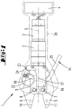
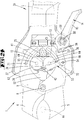
- a motor-driven pressing tool 1 Shown and described is a motor-driven pressing tool 1, which has an electric motor 2 and a transmission 3 in a rod-like arrangement in succession. On the side facing away from the transmission 3 of the electric motor 2, a rechargeable battery 4 is provided in a preferred further rod-like arrangement.
- a housing 34 is dashed in FIG. 1 indicated.
- the pressing tool 1 is also preferably only rod-like, without branching housing part (regarding a plan view approximately according to FIG. 1 ), formed roughly in the contour of a flashlight.
- a contour against one Grip area thickened head area is determined by the outer contour of the compression jaws or one of these covering (and with respect to the movement with some freedom in the closed position surrounding) housing part.
- an accumulator is preferably arranged at the end opposite the working area. This one can be like in FIG. 1 seen, mean a thickening of the housing or the rod end. However, it can also be aligned with the contour of the grip area, that is to say as a further extension of the grip area.
- the working range of the pressing tool 1 is formed by two pressing jaws 5, 6, both of which are rotatable, in the exemplary embodiment via axes 7, 8 are mounted pivotably on a support member 9 of the pressing tool 1.
- the pressing jaws can be formed immediately with a cutting and / or pressing geometry, which is not shown in detail. Such a configuration is for example in the press jaws of the aforementioned DE 197 09 017 A1 provided known pressing tool. Alternatively, press inserts can also be fastened to the work areas of the compression jaws. For this purpose, for example, the design of a pressing tool according to the DE 198 02 287 C1 or the US 6,053,025 A directed.
- On the back of the respective working area 10, 11 of a pressing jaw 5, 6, a loading area 12, 13 extending in the longitudinal direction of the pressing jaw is formed on each pressing jaw.
- the longitudinal direction of the Beauftschungs Kunststoffes in the embodiment the same longitudinal direction, which has the rod-shaped pressing tool 1 in total. It corresponds to a longitudinal axis L of the pressing tool.
- a loading area is preferably on the inside edge one Pressing jaw trained. In the case of two pressing jaws, the loading regions are preferably formed facing one another.
- a compression jaw 5, 6 transversely to the axes 7, 8 elongated, d. H. is formed with a greater length than width. Also in this respect results in a longitudinal direction of the compression jaws 5, 6.
- an urging member 36 (see, for example, FIG FIG. 2 ) intended.
- the loading member 36 is relative to the embodiment in the two loading areas 12, 13 of the embodiment also two compression jaws 5, 6 movable. It is preferable to move in the longitudinal direction of a pressing jaw 5, 6 or of a loading area 12, 13 of a pressing jaw.
- biasing member 36 is preferably linearly movable and movable in the longitudinal direction of the loading regions 12, 13 both by exerting manual force by means of a lever member 14 as well as by said motor.
- the loading member may also be movable only by motor.
- a fixed spindle 25 is provided in the longitudinal direction of the compression jaws 5, 6.
- This spindle is fixed in the axial direction. More preferably, the spindle is also stationary in the radial direction. But it is rotatable about its longitudinal axis to perform the spindle function.
- this spindle which in accordance with their longitudinal direction in preferably lateral coverage, compare overlap area u relative to the top view FIG. 2 , extends to one or both loading areas 12, 13, the loading part 36 can be driven in a compact design for the final action on the compression jaws 5, 6.
- this constructive design also has meaning without an additional or preferably first, possible manual operation by means of the lever part 14.
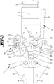
- a further general identification is given by the fact that the loading part 36, preferably moved by the spindle 25, is to be moved from a position close to the working area 10 or 11 to a position remote from the working area 10 or 11 (see also FIG difference Figures 2 . 3 ).
- the lever member 14 is designed in some embodiments and preferably angular.
- a first lever portion 15 having a second longitudinal extent is arranged to extend at least partially relative to a bottom view of the pressing tool in register with the engine and / or transmission. It serves as a handling area, which can be detected by a hand, which also encompasses the engine / transmission area.
- the lever part 14 is based on a plan view according to FIG. 2 on one side of the spindle 25, more generally on one side of the longitudinal axis 4 of the hand-pressing tool, free for actuation, but according to one of the embodiments described on the other side of the longitudinal axis L and / or the spindle 25 rotatably mounted (see also below further explained rotary storage area 18).
- a second lever portion 16 which has a first longitudinal extent, extends for this purpose angularly, wherein in the angular interior of the engine and the transmission extends.
- the second lever section 16 also crosses a longitudinal axis L of the pressing device.
- the included between the first and second longitudinal extension angle is preferably an obtuse angle, more preferably an angle between 90 ° and 150 °.
- the lever part 14 and, in the exemplary embodiment, preferably the lever section 16 are preferably connected in an articulated manner to the loading part 36.
- a rotary joint 17 is provided on the loading part 36 and the lever part 4 or the lever arm part 16.
- the lever part 14 is preferably double, extending on both sides of the loading part 36, or at least preferably fork-shaped in the region of the loading part 36, is formed.
- the two parts or the fork area are also approximately in a plan view according to FIG. 2 the pressing tool preferably in coverage.
- the swivel joint 17 is preferably arranged between the housing-fixed mounting of the lever part 14 and the free end of the first lever section 15.
- the articulated connection between the lever part 14 and the biasing member 36 may be provided so that the lever portion on which the articulated connection is formed to the biasing member 36, at least in its longitudinal direction relative to the biasing member 36 can move.
- the mentioned housing-fixed mounting of the lever part 14 is preferably formed on the lever arm portion 15 facing away from the end.
- a Storage area preferably a rotary storage area 18, formed on the support member 9.
- the lever part 14 is movable in the storage area 18 relative to the holding part 9 or a housing 34 of the pressing tool 1.
- a slot 19 is formed for this purpose in the relevant area of the lever member 14, which is penetrated, for example, by a pin 20 secured to the support member.
- a spring 22 which is preferably biased.
- the spring 22 seeks to move the anvil 21 away from the housing-fixed bearing provided by the pin 20 so that the pin 20 is located in the slot 19 at a first end portion.
- the lever member 14 is acted upon by manual force and the compression jaws 5, 6 pivoted thereby, they can be initially moved by manual force into a position in which a captured between the compression jaws part, such as a lug, but is practically not pressed , In this movement section, the storage position does not change.
- the rotating storage area 18 acts like a fixed bearing. If the hand force on the lever part is then further increased, finally the force of the spring 22 is overcome, so that the counter bearing 21 is moved toward the pin 20 against the force of the spring 22.
- This manual force corresponds to the clamping pressure applied by hand to that in a press jaw, in the exemplary embodiment preferably directly between the associated press jaws 5, 6, salaried, workpiece.
- This said movement also causes a switch 23 is no longer acted upon by the lever member 14.
- the lever part 14, or more specifically in the embodiment of the lever portion 15 has to act on the Switch 23 until the said movement takes place, preferably a round portion 35 which has a radius with respect to the peripheral edge of the round portion 35, the radial distance of a point of this edge portion to the first storage location of the lever member 14, ie a geometric center with respect to a Top view of the pin 20, corresponds. If the switch 23 is no longer acted upon by the lever part 14, thereby a spring-biased switching arm 24 of the switch 23 extend and thus effect a circuit. In fact, in this case the electric motor 2 is turned on, whereby a spindle 25 is rotated via a gear.
- the Verfahrteil 26 On the spindle 25 moves a Verfahrteil 26, which is driven by the motor rotated in rotation spindle 25 against the biasing member 36 and then further with motor force the biasing member 36 further in the longitudinal direction, in the direction of the electric motor 2, the Verpresstechnikmaschinees 1 moves ,
- the Verfahrteil 26 may be formed to cooperate with the spindle 25 as a spindle nut.
- the compression jaws 5, 6 are preferably moved by the biasing member 36 via links 27, 28.
- One or both arms 27, 28 are on the one hand rotatably movable with the biasing member 36 and on the other hand rotatable connected to a compression jaw 5, 6.
- the connection with a compression jaw 5, 6 is here further preferably from a relative to an axis 7, 8 at a working area 10, 11 opposite end of a compression jaw 5, 6 given.
- the links, relative to the longitudinal extension of the pressing jaws 5, 6, perform an erection movement until they are oriented almost linearly in relation to one another. This results in a toggle effect.
- the links 27, 28 can be moved to a dead center position which preferably corresponds to a position of alignment in practice, or even to a certain extent beyond that. But this initially, preferably until shortly before the dead center, against the force of a first part 30 of the return spring 29. In a wider range then against the force of a second part 31 of the return spring 29th
- the second part 31 of the return spring 29 has a steeper spring characteristic, and causes in any case with drop in engine power a return movement of the biasing member 13 so far that the over-center position is no longer given and according to the return spring 29 and then in particular by the first part 30 of the Return spring 29 a return movement in the position according to FIG. 1 he follows.
- the return movement of the loading part 13 is preferably bound to the return movement of the moving part 26.
- the Verfahrteil 26 is preferably moved by means of the motor now oppositely rotated spindle 25 and thus releases the space for the spring-assisted return movement of not so far engaged with the spindle so far in the applying part 13th
- a second switch 32 which causes a shutdown of the electric motor with a corresponding position of the biasing member 13 and the Vertexeils 26 and preferably initiates a reverse rotation of the electric motor in the embodiment, for moving the Verfahrteils 26 by means of the spindle 25 back in the starting position.
- a third switch 33 is further preferably provided, which ultimately shuts off the electric motor until a new compression takes place.
- the loading member 36 and the traversing member 26 are coaxial and although in the embodiment on the spindle 25 movable.
- the Verfahrteil 26 is directly in threaded engagement with the spindle 25, while the biasing member 36 engages over the spindle sleeve-like and without engagement with the spindle is movable relative thereto.
- FIG. 4 is a perspective view of an overall hand-pressing tool reproduced.
- housing shells 37, 38 can be seen, which cover in the embodiment of two compression jaws 5, 6 in a lower, ie the trunk device facing area.
- the overlap is preferred and as in the embodiment visible on the axes 7, 8, by which the pressing jaws 5, 6 are pivotable out.
- the lever member 16 projects with respect to the lever portion 15 down, d. H. Humpfieri beau, on one side of a housing shell 37, 38 out. With regard to a grip area 39, the lever part 14 or the lever section 15 is on the upper side, d. H. arranged pressback side.
- FIG. 5 remove Further details can also be the FIG. 5 remove.
- the lever portion 15 in the actuated state as he FIG. 5 is based, fits into a correspondingly shaped housing receptacle 40.
- the support member 9, which supports the axes 7, 8 of the compression jaws 5, 6, preferably also has a guide recess 41.
- the guide recess 41 is further preferably formed as a longitudinal slot.
- a Guide extension 42 of the biasing member 36 may be performed in the guide recess 41.
- the guide extension 42 can extend as far as the guide recess 41, as for example FIG. 7 can also be seen that it serves as a counter-stop for the lever portion 16.
- the mouth side of the hand-pressing tool or spindle end side provided switch 33 may preferably, regardless of the in FIG. 6 respectively.
- FIG. 7 For example, shown embodiment, be acted upon by a rotatably mounted lever 43.
- the lever portion 16 acts on the lever 43 and this on the switch 33rd
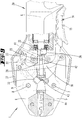
- FIG. 8 is the hand-operated position, which does not trigger any motor actuation shown.
- a compact 44 is already taken in the pliers mouth with a certain investment pressure.
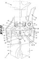
- FIG. 9 is the complete closure of the compression jaws 5, 6, shown after the engine operation.
- a part of the loading part 36, here the guide extension 42, is also used for actuating the switch 32.
- the related to the Figures 10 and 11 illustrated further embodiment is characterized in that the lever member 14 acts by means of a link 45 on a switching member 46.
- the switching member 46 is mounted according to the lever portion 16 in the embodiment described above and thus biased in the same way by the spring 22.
- the switching member 46 rotates about a support point on the guide extension 42 so that its end associated with the switch 23 moves away therefrom (against the force of the spring 22), thereby switching the motor to actuate the actuating member 36.
- the lever 14 mounted on the side of the spindle 25, see.
- a circuit board 48 is arranged.
- the board 48 preferably supports all the switches 23, 32 and 33 provided here.
- a fourth switch 49 is preferably also provided.
- the switch 49 is used to interrupt an engine operation when the lever portion 15 is moved opposite to a movement that is feasible to a compression, which is directed in the embodiment and preferably on the handle portion 39 to.
- an extension of the lever 15 can act on the switch 49, whereby the motor is switched off, so that no further compression takes place.
- a release of the loading part for a return movement can be carried out so switch-operated.
- the release also includes preferably that the motor is turned on again in the opposite direction of rotation, thereby the traverse unit is moved back and so the release of the loading member takes place.
- a light source 50 is further arranged in the embodiment in the form of a light emitting diode.
- the light source 50 radiates in the direction a movement of the loading member 36, directed towards the free end of the compression jaws 5, 6 out.
- a corresponding opening or light passage is also preferably provided in one or both of these housing shells 37, 38.
- FIG. 8 shows that associated with a free end of the spindle 25, a lubricant reservoir 51 is provided.
- the lubricant reservoir 51 is received in a sleeve 52, which is directed with its opening directed towards the spindle, preferably also in engagement with the free end of the spindle.
- FIGS. 12 to 19 is another embodiment and the related sequence is described at an operation. Identical parts are provided with the same reference numerals.
- FIGS. 12 to 19 An in the embodiment of the Figures 10 and 11 formed as a handlebar 45 intermediate part is in the embodiment of FIGS. 12 to 19 formed as an intermediate lever 53.
- the intermediate lever 53 is fixed to the housing via an axle 54.
- the intermediate lever 53 which can be seen in the same way for the lever or lever portion 16 or the handlebar 45 of the previous embodiments, is guided below the board 48.
- the intermediate lever 53 is further preferably designed as an angle lever. At an angle preferably approximately at right angles to each other extending areas on the one hand, the interaction with the lever member 14 is given and on the other hand, the interaction with the guide extension 42nd
- the interaction with the guide extension 42 is preferably given by positive engagement.
- a step recess on the intermediate lever 53 creates a loading surface, which faces away from the press jaw on the guide extension 42 rests.
- the interaction of the intermediate lever 53 and the lever member 14 is also preferably given in a form-fitting manner in this embodiment.
- a toothing 55 is formed. In this case, preferably only a few teeth, in the embodiment two teeth, respectively realized.
- the teeth 56 of the lever member 14 have a greater width than the teeth 57 of the intermediate lever 53.
- the intermediate lever 53 is preferably made of a harder or more resilient material than the lever member 14.
- the lever part 14 is preferably made of a hard plastic, while the intermediate lever part 53 is a metal part.
- the triggering of the compression by overcoming a manually applied clamping pressure is in the embodiment of FIGS. 12 to 19 given by a mobility of the lever member 14 relative to the housing.
- the lever part 14 has a bearing axle 58, which is accommodated on the housing side in each case in a slot 59.
- a housing side supported compression spring 60 is in the initial state about the FIG. 14 the lever member 14 biased with its bearing axis 58 against one end of the slot 59.
- the lever member 14 is displaced together with the bearing shaft 58 in the or the slot / slots 59, in the embodiment in the direction of the spindle 25 Switch 62, the functionally already described above Switch 23 corresponds, operated.
- the switch 62 is acted upon directly by the lever member 14.
- the achievement of the injection position is, as in the previously described embodiments, detected by the switch 32.
- the switch 33 is provided for the beginning and the end of the engine operation. When motor operation is initiated via the switch 62, the switch 33 detects the actual movement of the traveling member 26 and / or the return of the traveling member 26 to its original position, after which the engine shuts off.
- the intermediate part or concretely in the embodiment of the intermediate lever 53 can be moved in the opposite direction by means of the lever member 14 also with respect to its urging movement. Approximately after reaching the position of FIG. 16 when an emergency stop is desired, the intermediate lever 53 may be in In this case, based on the illustration, to be moved counterclockwise, so as to actuate the switch 61, see. FIG. 18 (Intermediate position) and FIG. 19 ,
- the bearing shaft 58 is further preferably non-rotatably connected to the lever member 14. This results in a certain frictional action when moving the lever member 14 with respect to the compression spring 60. This counteracts unintentional movement of the lever member 14 in the emergency exhibition.
- Such increased friction can also be achieved by other measures. For example, by a certain close fit of the bearing shaft 58 in the slot 59th
- FIGS. 20 to 25 are, in a schematic representation, reproduced embodiments in which the loading of the compression jaws (which may also be cutting jaws as above in the context of the invention) represented by rolling elements, in particular rollers.
- rollers 63, 64 attached to a respective Verpressbacke 5, 6. They are rotatable about a respective axis 65, 66 fixedly connected to the pressing jaws 5, 6.
- the loading member 36 has in this embodiment Abrollkanten 67, 68 which act on the rollers 63, 64 relative to the spindle 25 and a linear guide in the process of the biasing member 36 and hereby the compression jaws at its rear end, ie the electric motor or .,
- the end region of the compression jaws 5, 6 facing the gripping region can be acted upon by spreading or diverging.
- the rolling edges 67, 68 are formed to the mouth side of the tool expanding in terms of their edge contour. It is understood that in a contrast lateral view of the rolling edge, this preferably represents a rolling surface.
- the rolling surface may in this case a height (extension in the axial direction) of the rollers 63, 64 correspond to or a part of this height, about 1 / 10-9 / 10th of the height.
- the loading member 36 further has one or two guide recesses 69 and 70, with which the compression jaws 5, 6, in the embodiment via a respective pin 71, 72 cooperate.
- the guide recess 69 and 70 is as shown preferably designed as a slot.
- This guide recess 69, 70 and the cooperating pin 71, 72 serve only for positive return movement of the compression jaws 5, 6 in the open position according to FIG. 20 after performing a compression, ie from the position according to FIG. 21 , Preference is given here practically no significant forces, in particular no compression forces transmitted.
- the formation of a corresponding recess could also be provided on the compression jaw and the pin on the biasing member.
- the loading member 36 preferably has a guide extension 42, and are due to an action by the lever member 14, preferably on the guide extension 42 to move the compression jaws 5, 6 via a first-time manual operation in a first clamping position.
- the lever member 14 preferably on the guide extension 42 to move the compression jaws 5, 6 via a first-time manual operation in a first clamping position.
- this also applies to all embodiments described here.
- the embodiment of the Figures 22 and 23 differs from the embodiment of the Figures 20 and 21 essentially in that the rollers 63, 64 are mounted on the loading member 36 and proceed with this. Accordingly, the axes 65, 66 are attached to the loading part 36.
- the loading member 36 for supporting the axes 65, 66 and the pins 71, 72 in the embodiment, one or two opposite (in the illustrations, only one visible) support bracket 73 on.
- a support bracket extends at right angles to a longitudinal axis L or to an extent of the spindle 25.
- the compression jaws 5, 6 have to cooperate with the rollers 63, 64 in the embodiments of the FIGS. 20 to 25 each have a concave loading area 12, 13.
- the spindle 25 or a corresponding linear guide the loading member 36 continues to penetrate are in further detail in the embodiment of Figures 24 and 25 prefers four rollers 63, 64 are provided, of which in each case two, preferably in alignment, are arranged one above the other. Between two respective cooperating rollers 63, 64, these mutually arranged pairs, there is correspondingly a tread-like distance, which is used for the required through-opening for the spindle 25 and the linear guide.
Landscapes
- Engineering & Computer Science (AREA)
- Mechanical Engineering (AREA)
- Manufacturing & Machinery (AREA)
- Forests & Forestry (AREA)
- Life Sciences & Earth Sciences (AREA)
- Press Drives And Press Lines (AREA)
- Hand Tools For Fitting Together And Separating, Or Other Hand Tools (AREA)
- Manufacturing Of Electrical Connectors (AREA)
- Manufacturing And Processing Devices For Dough (AREA)
- Surgical Instruments (AREA)
- Details Of Spanners, Wrenches, And Screw Drivers And Accessories (AREA)
- Food-Manufacturing Devices (AREA)
- Manipulator (AREA)
Claims (15)
- Outil de compression manuel motorisé (1), en particulier une pince à sertir, comprenant un élément de support fixe (9) dans lequel sont supportées deux mâchoires de compression (5, 6) aptes à pivoter chacune autour d'un axe de pivotement, lesquelles mâchoires de compression(5, 6) forment d'un côté de l'axe de pivotement une région de travail (10, 11) et de l'autre côté de l'axe de pivotement une région d'actionnement (12) s'étendant dans la direction longitudinale des mâchoires de compression 5, 6), dans lequel la région d'actionnement (12) est susceptible être sollicitée par un élément d'actionnement (36) déplaçable relativement à la région d'actionnement (12) pour exécuter une compression et, dans une vue de dessus de l'outil de compression manuel (1) dans laquelle l'axe de pivotement est représenté sous la forme d'un point, une broche filetée (25) axialement fixe dans la direction d'extension longitudinale des mâchoires de compression et entrainée par un moteur électrique s'étend jusqu'à un recouvrement de la région d'actionnement transversalement à un axe longitudinal de la broche filetée (25), dans lequel la broche filetée (25) sert à l'actionnement motorisé d'un élément mobile qui est susceptible d'être amené à venir agir en transmission d'efforts sur l'élément d'actionnement (36), caractérisé en ce que l'outil de compression (1) est de construction allongée à la manière d'une tige, avec le moteur électrique, la broche filetée (25) et un mécanisme de transmission entre le moteur électrique et la tige filetée (25) qui sont agencés l'un derrière l'autre à la manière d'une tige, et en ce que la broche filetée (25) s'étend longitudinalement au centre entre des régions d'actionnement (12, 13) des mâchoires de pressage (5, 6).
- Outil de compression selon la revendication 1, caractérisé en ce que, pour effectuer le pressage, l'élément d'actionnement (36) doit être déplacée d'une position proche de la région de travail à une position éloignée de la région de travail.
- Outil de compression selon l'une des revendications précédentes, caractérisé en ce que les mâchoires de compression (5, 6) peuvent être déplacées manuellement dans une position de serrage et en ce qu'un déclenchement du déplacement motorisé est provoqué en fonction d'une pression de serrage développée manuellement.
- Outil de compression selon l'une des revendications précédentes, caractérisé en ce qu'il est possible d'agir sur l'élément d'actionnement (36) au moyen d'un élément de transmission, dans lequel l'élément de transmission est préférentiellement un levier (14), dans lequel le levier (14) est en outre préférentiellement relié de manière articulée avec l'élément d'actionnement (36) et/ou le levier (14) est monté sur l'élément de support (9) dans une région de montage, dans lequel, de manière préférentielle, le levier (14) est déplaçable dans la région de montage relativement à un boîtier (34) et/ou le levier (14) est déplaçable hors d'un premier emplacement de montage de par l'effort manuel exercé sur le levier (14) qui excède une valeur de seuil et/ou un démarrage ou arrêt du moteur électrique (2) est susceptible d'être déclenché par un déplacement du levier (14) dans la région de montage.
- Outil de compression selon l'une des revendications précédentes, caractérisé en ce que l'élément d'actionnement (36) agit sur les mâchoires de compression (5, 6) par le biais d'une bielle (27) et/ou l'élément d'actionnement (36) agit sur les mâchoires de compression (5, 6) par le biais d'un ou plusieurs rouleaux (63, 64).
- Outil de compression selon la revendication 5, caractérisé en ce que l'un ou plusieurs rouleaux (63, 64) sont liés avec la mâchoire de compression (5, 6) ou qu'un ou plusieurs rouleaux (63, 64) sont liés à l'élément d'actionnement (36).
- Outil de compression selon l'une des revendications précédentes, caractérisé en ce que l'élément d'actionnement (36) et l'élément mobile (26) sont déplaçables de manière coaxiale et/ou en ce que l'élément d'actionnement (36) doit être déplacé à l'encontre de l'effort d'un ressort de rappel (29), dans lequel le ressort de rappel (29) présente de préférence une courbe caractéristique d'élasticité plus raide pour un pivotement avancé d'une mâchoire de compression (5, 6) hors d'une position de repos dans une position de compression que pour un début du pivotement, dans lequel le ressort de rappel (29) est en outre préférentiellement réalisé en plusieurs parties.
- Outil de compression selon l'une des revendications 4 à 7, caractérisé en ce que, en dépendance à un dépassement d'une valeur de seuil d'effort avant exécution complète d'une compression, une libération du levier (14) provoque uniquement un arrêt d'un déplacement des mâchoires de compression (5,6), dans lequel préférentiellement la valeur de seuil d'effort est déterminable par une mesure du courant du moteur.
- Outil de compression selon l'une des revendications précédentes, caractérisé en ce qu'une libération de l'élément d'actionnement (36) aux fins d'un déplacement en arrière est susceptible d'être réalisée par actionnement d'un interrupteur avant l'exécution complète d'une compression afin de permettre un pivotement des mâchoires de compression (5,6) dans une position ouverte, dans lequel préférentiellement la libération de l'élément d'actionnement (36) est susceptible d'être réalisée au moyen d'un déplacement du levier (14) par application d'un effort manuel qui est différent du déplacement du levier (14) lors d'une compression et/ou en ce que le levier (14) agit sur un élément de commutation (46) déplaçable par pivotement par le biais d'une bielle (45) et/ou en ce que le levier (14) est monté à rotation, dans la vue de dessus, sur le côté de la broche (25) sur laquelle il s'étend librement aux fins d'actionnement.
- Outil de compression selon la revendication 9, caractérisé en ce que deux interrupteurs (23, 32, 33, 61, 62) ou plus sont prévus, dans lequel quatre interrupteurs (23, 32, 33, 61, 62) sont de préférence prévus et/ou en ce que tous les interrupteurs (23,32, 33, 61, 62) sont prévus sur une platine commune (48).
- Outil de compression selon l'une des revendications précédentes, caractérisé en ce qu'est prévu un moyen d'éclairage (50) rayonnant dans une direction de déplacement de l'élément d'actionnement.
- Outil de compression selon l'une des revendications 10 ou 11, caractérisé en ce que le moyen d'éclairage (50) est agencé sur la platine (48) .
- Outil de compression selon l'une des revendications précédentes, caractérisé en ce qu'est prévu une réserve de lubrifiant (51) associée à la broche (25), dans lequel la réserve de lubrifiant (51) est de préférence prévue à un côté d'extrémité de la broche (25).
- Outil de compression selon l'une des revendications 4 à 13, caractérisé en ce que le levier (14) agit sur l'élément d'actionnement (36) par le biais d'un levier intermédiaire (53), dans lequel préférentiellement le levier (14) déplace le levier intermédiaire (53) au moyen d'une denture et/ou en ce que le levier (14) est une pièce en matière plastique et/ou en ce que le levier intermédiaire (53) est une pièce métallique.
- Outil de compression selon l'une des revendications précédentes, caractérisé en ce qu'un déplacement partiel en arrière de l'élément d'actionnement (36) et/ou de l'élément mobile (26) est susceptible d'être prédéfini en conséquence de la mémorisation d'une valeur relative à la position de la broche correspondant par exemple à un début de compression, dans lequel préférentiellement la mémorisation et/ou le déplacement partiel en arrière est susceptible d'être déclenché par une séquence d'actionnement.
Applications Claiming Priority (4)
| Application Number | Priority Date | Filing Date | Title |
|---|---|---|---|
| DE102012106186 | 2012-07-10 | ||
| DE102013102037 | 2013-03-01 | ||
| EP13735258.9A EP2872293B1 (fr) | 2012-07-10 | 2013-07-09 | Outil de compression |
| PCT/EP2013/064472 WO2014009363A1 (fr) | 2012-07-10 | 2013-07-09 | Outil de compression |
Related Parent Applications (2)
| Application Number | Title | Priority Date | Filing Date |
|---|---|---|---|
| EP13735258.9A Division EP2872293B1 (fr) | 2012-07-10 | 2013-07-09 | Outil de compression |
| EP13735258.9A Division-Into EP2872293B1 (fr) | 2012-07-10 | 2013-07-09 | Outil de compression |
Publications (2)
| Publication Number | Publication Date |
|---|---|
| EP3219444A1 EP3219444A1 (fr) | 2017-09-20 |
| EP3219444B1 true EP3219444B1 (fr) | 2019-10-23 |
Family
ID=48782316
Family Applications (2)
| Application Number | Title | Priority Date | Filing Date |
|---|---|---|---|
| EP13735258.9A Active EP2872293B1 (fr) | 2012-07-10 | 2013-07-09 | Outil de compression |
| EP17165768.7A Active EP3219444B1 (fr) | 2012-07-10 | 2013-07-09 | Outil de compression |
Family Applications Before (1)
| Application Number | Title | Priority Date | Filing Date |
|---|---|---|---|
| EP13735258.9A Active EP2872293B1 (fr) | 2012-07-10 | 2013-07-09 | Outil de compression |
Country Status (14)
| Country | Link |
|---|---|
| US (2) | US9993885B2 (fr) |
| EP (2) | EP2872293B1 (fr) |
| KR (1) | KR102061119B1 (fr) |
| CN (1) | CN104540644B (fr) |
| AU (1) | AU2013289255B2 (fr) |
| BR (1) | BR112015000538A2 (fr) |
| CA (1) | CA2877806C (fr) |
| DE (1) | DE102013107217A1 (fr) |
| ES (1) | ES2642388T3 (fr) |
| IN (1) | IN2014DN10958A (fr) |
| MX (1) | MX357359B (fr) |
| RU (1) | RU2656907C2 (fr) |
| WO (1) | WO2014009363A1 (fr) |
| ZA (1) | ZA201409504B (fr) |
Families Citing this family (51)
| Publication number | Priority date | Publication date | Assignee | Title |
|---|---|---|---|---|
| DE102014116562A1 (de) | 2014-11-12 | 2016-05-12 | Gustav Klauke Gmbh | Motorbetriebenes Handwerkzeug, Verfahren zur Benutzung eines Handwerkzeuges, Kombination aus einem motorbetriebenen Handwerkzeug und Handschuh |
| DE102015106623A1 (de) | 2015-04-29 | 2016-11-03 | Gustav Klauke Gmbh | Werkzeug zum Schneiden und Verschließen eines Schlauches |
| NL2014868B1 (nl) * | 2015-05-27 | 2017-01-02 | Jpm Beheer B V | Reddingsgereedschap. |
| CN105140757A (zh) * | 2015-09-22 | 2015-12-09 | 国网浙江宁波市鄞州区供电公司 | 一种电控铜鼻子压线钳 |
| US20170119123A1 (en) * | 2015-10-29 | 2017-05-04 | Nina Butler Sanders | Method and apparatus for attaching false hair |
| CN109789542B (zh) * | 2016-10-07 | 2023-02-03 | 古斯塔夫.克劳克有限责任公司 | 工具 |
| US10512964B2 (en) * | 2016-12-14 | 2019-12-24 | Ridge Tool Company | Electrically powered crimp tool |
| US10675805B2 (en) * | 2016-12-14 | 2020-06-09 | Ridge Tool Company | Electrically powered crimp tool and method of using |
| US10933478B2 (en) * | 2017-02-12 | 2021-03-02 | Verco Decking Inc. | Decking tool |
| IT201700015948A1 (it) * | 2017-02-14 | 2018-08-14 | A M F S P A | Dispositivo e metodo per l’applicazione di inserti su supporti laminari e kit per uso in tale dispositivo |
| EP3396796B1 (fr) * | 2017-04-25 | 2021-07-21 | WEZAG GmbH & Co. KG | Outil de compression, de sertissage ou de découpe et module d'outils |
| US10847944B2 (en) * | 2017-05-16 | 2020-11-24 | Elpress Ab | Method for monitoring a crimping process |
| EP3513911B2 (fr) * | 2018-01-17 | 2025-03-26 | Emerson Professional Tools AG | Machine de pressage |
| CN109319373B (zh) * | 2018-01-25 | 2023-12-26 | 深圳市建艺装饰集团股份有限公司 | 一种人工板材搬运夹具 |
| JP6725595B2 (ja) * | 2018-06-28 | 2020-07-22 | ファナック株式会社 | クランプ装置 |
| US11870196B2 (en) | 2018-07-26 | 2024-01-09 | Hubbell Incorporated | Battery powered portable crimp tool with C-head |
| US11659909B2 (en) * | 2018-08-29 | 2023-05-30 | Dongguan Bidisco Electric Co., Ltd. | Multifunctional hair straightening and curling device |
| DE102018121971A1 (de) * | 2018-09-10 | 2020-03-12 | Gustav Klauke Gmbh | Presswerkzeug |
| CN108971605B (zh) * | 2018-09-29 | 2020-09-04 | 嘉兴诺丁汉工业设计有限公司 | 一种用于抢险救灾的电动剪切器 |
| JP2020069259A (ja) * | 2018-11-01 | 2020-05-07 | 株式会社マキタ | 充電式シャー |
| EP3650176B1 (fr) * | 2018-11-07 | 2025-12-24 | Emerson Professional Tools AG | Machine à presser |
| EP3943250B1 (fr) * | 2019-03-18 | 2024-08-28 | Ogura & Co., Ltd. | Outil auxiliaire et unité d'actionnement |
| EP4022188B1 (fr) | 2019-08-29 | 2025-07-23 | Milwaukee Electric Tool Corporation | Outil hydraulique avec un piston de vérin intégrant un ensemble anti-surcharge |
| US12202117B2 (en) | 2019-09-03 | 2025-01-21 | Milwaukee Electric Tool Corporation | Tool with hydraulic system for regenerative extension and two-speed operation |
| US11236849B2 (en) | 2019-09-04 | 2022-02-01 | Techtronic Cordless Gp | Pressing tool and method for a re-pressing operation |
| EP4007087B1 (fr) * | 2019-11-11 | 2024-02-07 | WEZAG GmbH & Co. KG | Pince à sertir |
| EP4065310B1 (fr) | 2019-11-27 | 2025-05-07 | Hubbell Incorporated | Ensemble d'entraînement d'outil à arbre d'entraînement principal intégré |
| RU196862U1 (ru) * | 2019-12-23 | 2020-03-18 | Акционерное общество "Военно-промышленная корпорация "Научно-производственное объединение машиностроения" | Универсальный ручной обжимной инструмент |
| DE102020120825A1 (de) | 2020-08-06 | 2022-02-10 | Gustav Klauke Gmbh | Pressbacken sowie Verfahren zur Herstellung eines Presslings und Verfahren zum Verpressen mit Pressbacken |
| BE1028682B1 (de) | 2020-10-09 | 2022-05-09 | Phoenix Contact Gmbh & Co | Werkzeugset zum Schneiden, Abisolieren und/oder Crimpen eines elektrischen Leiters |
| DE102020126487A1 (de) | 2020-10-09 | 2022-04-14 | Phoenix Contact Gmbh & Co. Kg | Werkzeugset zum Schneiden, Abisolieren und/oder Crimpen eines elektrischen Leiters |
| WO2022232554A1 (fr) | 2021-04-30 | 2022-11-03 | Milwaukee Electric Tool Corporation | Guide de vérin pour dispositif de sertissage |
| TWI762303B (zh) * | 2021-05-06 | 2022-04-21 | 陳君帆 | 鉗 |
| JP7079877B1 (ja) * | 2021-06-07 | 2022-06-02 | マクセルイズミ株式会社 | 電動工具 |
| DE102021122853A1 (de) | 2021-09-03 | 2023-03-09 | Gustav Klauke Gmbh | Paar von Werkzeugteilen, Verfahren zur Abisolierung eines Kabels sowie Verfahren zum Vercrimpen eines Presslings |
| CN118202532A (zh) | 2021-09-07 | 2024-06-14 | 豪倍公司 | 具有多级扳机的工具 |
| JP7850605B2 (ja) * | 2022-05-31 | 2026-04-23 | マクセルイズミ株式会社 | 電動工具 |
| WO2023237776A1 (fr) | 2022-06-10 | 2023-12-14 | Gustav Klauke Gmbh | Outil à main |
| US12611754B2 (en) | 2022-07-29 | 2026-04-28 | Black & Decker Inc. | Crimping and/or pinching accessory for power tool |
| USD1042074S1 (en) | 2022-09-07 | 2024-09-17 | Hubbell Incorporated | Handle for power tools |
| DE102022128652B4 (de) | 2022-10-28 | 2026-03-19 | Tkr Spezialwerkzeuge Gmbh | Verfahren zur Überprüfung der Qualität einer Crimpverbindung sowie System hierzu |
| KR102663865B1 (ko) * | 2022-11-14 | 2024-05-09 | 주식회사 사이트글라스 | 전동식 락킹 플라이어 |
| CA3224768A1 (fr) * | 2022-12-27 | 2024-06-27 | Max Co., Ltd. | Dispositif de coupe |
| DE102023102042A1 (de) | 2023-01-27 | 2024-08-01 | Gustav Klauke Gmbh | Abisolierwerkzeug, Paar von Werkzeugteilen für ein Abisolierwerkzeug sowie Verfahren zur Abisolierung eines Kabels |
| DE102023104915A1 (de) | 2023-02-28 | 2024-08-29 | Gustav Klauke Gmbh | Abisolierwerkzeug, Paar von Werkzeugteilen, Werkzeugelement sowie Verfahren zur Abisolierung eines Kabels |
| DE202023101054U1 (de) | 2023-03-06 | 2023-07-14 | Gustav Klauke Gmbh | Presswerkzeug mit einem Paar von Werkzeugteilen zum Vercrimpen eines Presslings sowie Paar von Werkzeugteilen für ein Presswerkzeug |
| DE102023111799A1 (de) | 2023-05-05 | 2024-11-07 | Gustav Klauke Gmbh | Werkzeug zum Vercrimpen oder Schneiden eines Werkstücks |
| CN117335240A (zh) * | 2023-10-24 | 2024-01-02 | 南京久驰机电实业有限公司 | 一种电动压接工具 |
| WO2025189051A1 (fr) * | 2024-03-06 | 2025-09-12 | Genesis Attachments, Llc | Accessoire de manipulation de matériau lié à un alésage |
| DE102024121358B3 (de) * | 2024-07-26 | 2025-11-13 | Tkr Spezialwerkzeuge Gmbh | Handhaltbare Zug- und Druckvorrichtung sowie Verfahren zur Herstellung einer Crimpverbindung |
| DE102024128736A1 (de) | 2024-10-04 | 2026-04-09 | Gustav Klauke Gmbh | Schneidwerkzeug zum Schneiden eines Schneidgutes |
Family Cites Families (21)
| Publication number | Priority date | Publication date | Assignee | Title |
|---|---|---|---|---|
| SU415154A1 (ru) * | 1970-11-19 | 1974-02-15 | Центральное проектно конструкторское бюро треста Электромонтажконстру кци | РУЧНОЙ ПРЕССf*-ли 15Mr-UiSA''"'-'1Ш |
| US5553478A (en) * | 1994-04-08 | 1996-09-10 | Burndy Corporation | Hand-held compression tool |
| DE4414967C2 (de) * | 1994-04-28 | 1997-07-17 | Weidmueller Interface | Servozange |
| SE9501251D0 (sv) * | 1995-04-03 | 1995-04-03 | Attexor Equip | Merhod and apparatus for carrying out an operatopn on a mechanical workpiece |
| DE19709017A1 (de) | 1996-12-20 | 1998-06-25 | Klauke Gmbh Gustav | Motorgetriebenes Preßwerkzeug |
| US6035775A (en) * | 1997-02-21 | 2000-03-14 | Novopres Gmbh Pressen Und Presswerkzeuge & Co. Kg | Pressing device having a control device adapted to control the pressing device in accordance with a servocontrol system of the control device |
| US5918370A (en) * | 1997-10-09 | 1999-07-06 | Jarvis Products Corporation | Hand held power assisted shears |
| DE19802287C1 (de) | 1998-01-22 | 1998-12-24 | Wezag Gmbh | Preßzange mit auswechselbaren Preßbacken |
| CN2407885Y (zh) * | 2000-03-07 | 2000-11-29 | 翁胜嘉 | 手持型挤压工具 |
| US6662620B1 (en) * | 2000-09-12 | 2003-12-16 | Black & Decker Inc. | Steel stud crimper |
| DE10161717B4 (de) * | 2001-12-15 | 2019-10-10 | Glw - Elektrotechnische Bauteile Kunststoffverarbeitung Gmbh | Vorrichtung zum nicht manuellen Vercrimpen |
| US7000448B2 (en) * | 2003-02-12 | 2006-02-21 | Emerson Electric Co. | Compression tool jawarm member |
| JP4254408B2 (ja) * | 2003-07-25 | 2009-04-15 | パナソニック電工株式会社 | ライト付き電動工具 |
| US7578159B2 (en) * | 2004-09-09 | 2009-08-25 | Emerson Electric Co. | Controlled cycle-life jaw assembly |
| DE102006003044B4 (de) | 2006-01-23 | 2015-10-08 | Gustav Klauke Gmbh | Hydraulisch angetriebenes Verpressgerät sowie Verfahren zum Verpressen eines Fittings |
| GB0721292D0 (en) * | 2007-10-30 | 2007-12-12 | Buchanan Nigel A | Hand operated gripping tool |
| US7603932B2 (en) * | 2006-07-28 | 2009-10-20 | Gm Global Technology Operations, Inc. | Method and apparatus for the separation of a first structure from a second structure at a connecting point |
| EP2062334A1 (fr) * | 2006-09-11 | 2009-05-27 | Cembre S.p.A. | Outil de presse et/ou de découpe hydraulique et mécanisme de conversion d'un mouvement rotatif en mouvement oscillant en translation pour cet outil |
| DE102008024018B4 (de) * | 2007-05-16 | 2024-04-18 | Gustav Klauke Gmbh | Verfahren zum Betreiben eines motorisch betätigten Handverpressgerätes und Handverpressgerät |
| DE102007028948B3 (de) * | 2007-06-22 | 2008-12-04 | Audi Ag | Werkzeug zur Montage eines Maschinenelementes |
| US20120102763A1 (en) * | 2010-10-28 | 2012-05-03 | Kett Tool Company | Metal Shear Head Center Blade |
-
2013
- 2013-07-09 BR BR112015000538A patent/BR112015000538A2/pt not_active Application Discontinuation
- 2013-07-09 WO PCT/EP2013/064472 patent/WO2014009363A1/fr not_active Ceased
- 2013-07-09 EP EP13735258.9A patent/EP2872293B1/fr active Active
- 2013-07-09 EP EP17165768.7A patent/EP3219444B1/fr active Active
- 2013-07-09 KR KR1020157003469A patent/KR102061119B1/ko active Active
- 2013-07-09 US US14/413,672 patent/US9993885B2/en active Active
- 2013-07-09 MX MX2015000263A patent/MX357359B/es active IP Right Grant
- 2013-07-09 CN CN201380042456.8A patent/CN104540644B/zh active Active
- 2013-07-09 RU RU2015104266A patent/RU2656907C2/ru active
- 2013-07-09 ES ES13735258.9T patent/ES2642388T3/es active Active
- 2013-07-09 DE DE102013107217.8A patent/DE102013107217A1/de not_active Withdrawn
- 2013-07-09 CA CA2877806A patent/CA2877806C/fr not_active Expired - Fee Related
- 2013-07-09 AU AU2013289255A patent/AU2013289255B2/en not_active Ceased
-
2014
- 2014-12-22 IN IN10958DEN2014 patent/IN2014DN10958A/en unknown
- 2014-12-23 ZA ZA2014/09504A patent/ZA201409504B/en unknown
-
2018
- 2018-05-17 US US15/982,463 patent/US10343227B2/en active Active
Non-Patent Citations (1)
| Title |
|---|
| None * |
Also Published As
| Publication number | Publication date |
|---|---|
| MX2015000263A (es) | 2015-04-10 |
| US20150251256A1 (en) | 2015-09-10 |
| CN104540644B (zh) | 2017-09-22 |
| RU2015104266A (ru) | 2016-08-27 |
| BR112015000538A2 (pt) | 2017-06-27 |
| EP3219444A1 (fr) | 2017-09-20 |
| IN2014DN10958A (fr) | 2015-09-18 |
| CN104540644A (zh) | 2015-04-22 |
| DE102013107217A1 (de) | 2014-01-16 |
| CA2877806C (fr) | 2020-07-07 |
| US10343227B2 (en) | 2019-07-09 |
| RU2656907C2 (ru) | 2018-06-07 |
| CA2877806A1 (fr) | 2014-01-16 |
| AU2013289255A2 (en) | 2015-05-14 |
| ZA201409504B (en) | 2016-08-31 |
| EP2872293B1 (fr) | 2017-08-30 |
| AU2013289255B2 (en) | 2017-08-10 |
| AU2013289255A1 (en) | 2015-01-29 |
| US20180264563A1 (en) | 2018-09-20 |
| KR20150038034A (ko) | 2015-04-08 |
| ES2642388T3 (es) | 2017-11-16 |
| KR102061119B1 (ko) | 2019-12-31 |
| EP2872293A1 (fr) | 2015-05-20 |
| WO2014009363A1 (fr) | 2014-01-16 |
| US9993885B2 (en) | 2018-06-12 |
| MX357359B (es) | 2018-07-05 |
Similar Documents
| Publication | Publication Date | Title |
|---|---|---|
| EP3219444B1 (fr) | Outil de compression | |
| EP1979110B1 (fr) | Appareil de sertissage hydraulique et procede de sertissage d'un raccord | |
| DE10328934B4 (de) | Motorischer Antrieb für chirurgische Instrumente | |
| EP3235074B1 (fr) | Pince de compression | |
| DE3333427C2 (fr) | ||
| DE102014100348A1 (de) | Presswerkzeug | |
| DE2219658C3 (de) | Kraftgetriebenes Werkzeug | |
| EP2234229B1 (fr) | Outil de dénudage de câbles électriques | |
| EP2106307A2 (fr) | Appareil à main de bordage | |
| EP3160686A1 (fr) | Dispositif de maintien pour maintenir en rotation une pièce à usiner | |
| EP3641987B1 (fr) | Bride de fixation et procédé de fonctionnement d'une bride de fixation | |
| EP2755804A1 (fr) | Machine-outil motorisée | |
| EP0274710A1 (fr) | Pince motorisée portable pour le serrage de cavaliers ou similaires | |
| DE102010032988A1 (de) | Hand-Sägemaschine mit einer Gegenhalteeinrichtung | |
| EP2223765B1 (fr) | Dispositif de pivotement d'un dispositif de rodage d'embouts d'électrodes de soudure par point | |
| DE3141248C2 (de) | Einrichtung zum Zuführen von Schrauben für einen motorbetriebenen Schraubenzieher | |
| EP3461569A1 (fr) | Pince de poinconnage à genouillère entraînée par moteur, en particulier par moteur électrique | |
| DE8802877U1 (de) | Motorisierte Schere mit autonomer Speisung | |
| EP2385891B1 (fr) | Pince destinée à l'assemblage par manchon coulissant | |
| EP2655016B1 (fr) | Pince | |
| DE19754275C2 (de) | Handschraubgerät | |
| DE10161717B4 (de) | Vorrichtung zum nicht manuellen Vercrimpen | |
| DE19811418B4 (de) | Spannzange für eine Schneidmaschine | |
| DE102006014973B4 (de) | Handhabungsgerät zum Umpositionieren von Teilen | |
| DE19620077C2 (de) | Vorrichtung zum Ziehen von Nägeln |
Legal Events
| Date | Code | Title | Description |
|---|---|---|---|
| PUAI | Public reference made under article 153(3) epc to a published international application that has entered the european phase |
Free format text: ORIGINAL CODE: 0009012 |
|
| STAA | Information on the status of an ep patent application or granted ep patent |
Free format text: STATUS: THE APPLICATION HAS BEEN PUBLISHED |
|
| AC | Divisional application: reference to earlier application |
Ref document number: 2872293 Country of ref document: EP Kind code of ref document: P |
|
| AK | Designated contracting states |
Kind code of ref document: A1 Designated state(s): AL AT BE BG CH CY CZ DE DK EE ES FI FR GB GR HR HU IE IS IT LI LT LU LV MC MK MT NL NO PL PT RO RS SE SI SK SM TR |
|
| STAA | Information on the status of an ep patent application or granted ep patent |
Free format text: STATUS: REQUEST FOR EXAMINATION WAS MADE |
|
| 17P | Request for examination filed |
Effective date: 20180110 |
|
| RBV | Designated contracting states (corrected) |
Designated state(s): AL AT BE BG CH CY CZ DE DK EE ES FI FR GB GR HR HU IE IS IT LI LT LU LV MC MK MT NL NO PL PT RO RS SE SI SK SM TR |
|
| STAA | Information on the status of an ep patent application or granted ep patent |
Free format text: STATUS: EXAMINATION IS IN PROGRESS |
|
| 17Q | First examination report despatched |
Effective date: 20180816 |
|
| GRAP | Despatch of communication of intention to grant a patent |
Free format text: ORIGINAL CODE: EPIDOSNIGR1 |
|
| STAA | Information on the status of an ep patent application or granted ep patent |
Free format text: STATUS: GRANT OF PATENT IS INTENDED |
|
| INTG | Intention to grant announced |
Effective date: 20190510 |
|
| GRAS | Grant fee paid |
Free format text: ORIGINAL CODE: EPIDOSNIGR3 |
|
| GRAA | (expected) grant |
Free format text: ORIGINAL CODE: 0009210 |
|
| STAA | Information on the status of an ep patent application or granted ep patent |
Free format text: STATUS: THE PATENT HAS BEEN GRANTED |
|
| AC | Divisional application: reference to earlier application |
Ref document number: 2872293 Country of ref document: EP Kind code of ref document: P |
|
| AK | Designated contracting states |
Kind code of ref document: B1 Designated state(s): AL AT BE BG CH CY CZ DE DK EE ES FI FR GB GR HR HU IE IS IT LI LT LU LV MC MK MT NL NO PL PT RO RS SE SI SK SM TR |
|
| REG | Reference to a national code |
Ref country code: GB Ref legal event code: FG4D Free format text: NOT ENGLISH |
|
| REG | Reference to a national code |
Ref country code: CH Ref legal event code: EP |
|
| REG | Reference to a national code |
Ref country code: IE Ref legal event code: FG4D Free format text: LANGUAGE OF EP DOCUMENT: GERMAN |
|
| REG | Reference to a national code |
Ref country code: DE Ref legal event code: R096 Ref document number: 502013013810 Country of ref document: DE |
|
| REG | Reference to a national code |
Ref country code: AT Ref legal event code: REF Ref document number: 1193151 Country of ref document: AT Kind code of ref document: T Effective date: 20191115 |
|
| REG | Reference to a national code |
Ref country code: NL Ref legal event code: MP Effective date: 20191023 |
|
| REG | Reference to a national code |
Ref country code: LT Ref legal event code: MG4D |
|
| PG25 | Lapsed in a contracting state [announced via postgrant information from national office to epo] |
Ref country code: NO Free format text: LAPSE BECAUSE OF FAILURE TO SUBMIT A TRANSLATION OF THE DESCRIPTION OR TO PAY THE FEE WITHIN THE PRESCRIBED TIME-LIMIT Effective date: 20200123 Ref country code: PL Free format text: LAPSE BECAUSE OF FAILURE TO SUBMIT A TRANSLATION OF THE DESCRIPTION OR TO PAY THE FEE WITHIN THE PRESCRIBED TIME-LIMIT Effective date: 20191023 Ref country code: GR Free format text: LAPSE BECAUSE OF FAILURE TO SUBMIT A TRANSLATION OF THE DESCRIPTION OR TO PAY THE FEE WITHIN THE PRESCRIBED TIME-LIMIT Effective date: 20200124 Ref country code: SE Free format text: LAPSE BECAUSE OF FAILURE TO SUBMIT A TRANSLATION OF THE DESCRIPTION OR TO PAY THE FEE WITHIN THE PRESCRIBED TIME-LIMIT Effective date: 20191023 Ref country code: LV Free format text: LAPSE BECAUSE OF FAILURE TO SUBMIT A TRANSLATION OF THE DESCRIPTION OR TO PAY THE FEE WITHIN THE PRESCRIBED TIME-LIMIT Effective date: 20191023 Ref country code: FI Free format text: LAPSE BECAUSE OF FAILURE TO SUBMIT A TRANSLATION OF THE DESCRIPTION OR TO PAY THE FEE WITHIN THE PRESCRIBED TIME-LIMIT Effective date: 20191023 Ref country code: BG Free format text: LAPSE BECAUSE OF FAILURE TO SUBMIT A TRANSLATION OF THE DESCRIPTION OR TO PAY THE FEE WITHIN THE PRESCRIBED TIME-LIMIT Effective date: 20200123 Ref country code: PT Free format text: LAPSE BECAUSE OF FAILURE TO SUBMIT A TRANSLATION OF THE DESCRIPTION OR TO PAY THE FEE WITHIN THE PRESCRIBED TIME-LIMIT Effective date: 20200224 Ref country code: NL Free format text: LAPSE BECAUSE OF FAILURE TO SUBMIT A TRANSLATION OF THE DESCRIPTION OR TO PAY THE FEE WITHIN THE PRESCRIBED TIME-LIMIT Effective date: 20191023 Ref country code: LT Free format text: LAPSE BECAUSE OF FAILURE TO SUBMIT A TRANSLATION OF THE DESCRIPTION OR TO PAY THE FEE WITHIN THE PRESCRIBED TIME-LIMIT Effective date: 20191023 |
|
| PG25 | Lapsed in a contracting state [announced via postgrant information from national office to epo] |
Ref country code: HR Free format text: LAPSE BECAUSE OF FAILURE TO SUBMIT A TRANSLATION OF THE DESCRIPTION OR TO PAY THE FEE WITHIN THE PRESCRIBED TIME-LIMIT Effective date: 20191023 Ref country code: RS Free format text: LAPSE BECAUSE OF FAILURE TO SUBMIT A TRANSLATION OF THE DESCRIPTION OR TO PAY THE FEE WITHIN THE PRESCRIBED TIME-LIMIT Effective date: 20191023 Ref country code: IS Free format text: LAPSE BECAUSE OF FAILURE TO SUBMIT A TRANSLATION OF THE DESCRIPTION OR TO PAY THE FEE WITHIN THE PRESCRIBED TIME-LIMIT Effective date: 20200224 |
|
| PG25 | Lapsed in a contracting state [announced via postgrant information from national office to epo] |
Ref country code: AL Free format text: LAPSE BECAUSE OF FAILURE TO SUBMIT A TRANSLATION OF THE DESCRIPTION OR TO PAY THE FEE WITHIN THE PRESCRIBED TIME-LIMIT Effective date: 20191023 |
|
| REG | Reference to a national code |
Ref country code: DE Ref legal event code: R097 Ref document number: 502013013810 Country of ref document: DE |
|
| PG2D | Information on lapse in contracting state deleted |
Ref country code: IS |
|
| PG25 | Lapsed in a contracting state [announced via postgrant information from national office to epo] |
Ref country code: ES Free format text: LAPSE BECAUSE OF FAILURE TO SUBMIT A TRANSLATION OF THE DESCRIPTION OR TO PAY THE FEE WITHIN THE PRESCRIBED TIME-LIMIT Effective date: 20191023 Ref country code: CZ Free format text: LAPSE BECAUSE OF FAILURE TO SUBMIT A TRANSLATION OF THE DESCRIPTION OR TO PAY THE FEE WITHIN THE PRESCRIBED TIME-LIMIT Effective date: 20191023 Ref country code: RO Free format text: LAPSE BECAUSE OF FAILURE TO SUBMIT A TRANSLATION OF THE DESCRIPTION OR TO PAY THE FEE WITHIN THE PRESCRIBED TIME-LIMIT Effective date: 20191023 Ref country code: EE Free format text: LAPSE BECAUSE OF FAILURE TO SUBMIT A TRANSLATION OF THE DESCRIPTION OR TO PAY THE FEE WITHIN THE PRESCRIBED TIME-LIMIT Effective date: 20191023 Ref country code: DK Free format text: LAPSE BECAUSE OF FAILURE TO SUBMIT A TRANSLATION OF THE DESCRIPTION OR TO PAY THE FEE WITHIN THE PRESCRIBED TIME-LIMIT Effective date: 20191023 Ref country code: IS Free format text: LAPSE BECAUSE OF FAILURE TO SUBMIT A TRANSLATION OF THE DESCRIPTION OR TO PAY THE FEE WITHIN THE PRESCRIBED TIME-LIMIT Effective date: 20200223 |
|
| PLBE | No opposition filed within time limit |
Free format text: ORIGINAL CODE: 0009261 |
|
| STAA | Information on the status of an ep patent application or granted ep patent |
Free format text: STATUS: NO OPPOSITION FILED WITHIN TIME LIMIT |
|
| PG25 | Lapsed in a contracting state [announced via postgrant information from national office to epo] |
Ref country code: SM Free format text: LAPSE BECAUSE OF FAILURE TO SUBMIT A TRANSLATION OF THE DESCRIPTION OR TO PAY THE FEE WITHIN THE PRESCRIBED TIME-LIMIT Effective date: 20191023 Ref country code: SK Free format text: LAPSE BECAUSE OF FAILURE TO SUBMIT A TRANSLATION OF THE DESCRIPTION OR TO PAY THE FEE WITHIN THE PRESCRIBED TIME-LIMIT Effective date: 20191023 |
|
| 26N | No opposition filed |
Effective date: 20200724 |
|
| PG25 | Lapsed in a contracting state [announced via postgrant information from national office to epo] |
Ref country code: SI Free format text: LAPSE BECAUSE OF FAILURE TO SUBMIT A TRANSLATION OF THE DESCRIPTION OR TO PAY THE FEE WITHIN THE PRESCRIBED TIME-LIMIT Effective date: 20191023 |
|
| PG25 | Lapsed in a contracting state [announced via postgrant information from national office to epo] |
Ref country code: MC Free format text: LAPSE BECAUSE OF FAILURE TO SUBMIT A TRANSLATION OF THE DESCRIPTION OR TO PAY THE FEE WITHIN THE PRESCRIBED TIME-LIMIT Effective date: 20191023 |
|
| REG | Reference to a national code |
Ref country code: CH Ref legal event code: PL |
|
| GBPC | Gb: european patent ceased through non-payment of renewal fee |
Effective date: 20200709 |
|
| REG | Reference to a national code |
Ref country code: BE Ref legal event code: MM Effective date: 20200731 |
|
| PG25 | Lapsed in a contracting state [announced via postgrant information from national office to epo] |
Ref country code: CH Free format text: LAPSE BECAUSE OF NON-PAYMENT OF DUE FEES Effective date: 20200731 Ref country code: LI Free format text: LAPSE BECAUSE OF NON-PAYMENT OF DUE FEES Effective date: 20200731 Ref country code: LU Free format text: LAPSE BECAUSE OF NON-PAYMENT OF DUE FEES Effective date: 20200709 Ref country code: GB Free format text: LAPSE BECAUSE OF NON-PAYMENT OF DUE FEES Effective date: 20200709 |
|
| PG25 | Lapsed in a contracting state [announced via postgrant information from national office to epo] |
Ref country code: BE Free format text: LAPSE BECAUSE OF NON-PAYMENT OF DUE FEES Effective date: 20200731 |
|
| PG25 | Lapsed in a contracting state [announced via postgrant information from national office to epo] |
Ref country code: IE Free format text: LAPSE BECAUSE OF NON-PAYMENT OF DUE FEES Effective date: 20200709 |
|
| REG | Reference to a national code |
Ref country code: AT Ref legal event code: MM01 Ref document number: 1193151 Country of ref document: AT Kind code of ref document: T Effective date: 20200709 |
|
| PG25 | Lapsed in a contracting state [announced via postgrant information from national office to epo] |
Ref country code: AT Free format text: LAPSE BECAUSE OF NON-PAYMENT OF DUE FEES Effective date: 20200709 |
|
| PG25 | Lapsed in a contracting state [announced via postgrant information from national office to epo] |
Ref country code: TR Free format text: LAPSE BECAUSE OF FAILURE TO SUBMIT A TRANSLATION OF THE DESCRIPTION OR TO PAY THE FEE WITHIN THE PRESCRIBED TIME-LIMIT Effective date: 20191023 Ref country code: MT Free format text: LAPSE BECAUSE OF FAILURE TO SUBMIT A TRANSLATION OF THE DESCRIPTION OR TO PAY THE FEE WITHIN THE PRESCRIBED TIME-LIMIT Effective date: 20191023 Ref country code: CY Free format text: LAPSE BECAUSE OF FAILURE TO SUBMIT A TRANSLATION OF THE DESCRIPTION OR TO PAY THE FEE WITHIN THE PRESCRIBED TIME-LIMIT Effective date: 20191023 |
|
| PG25 | Lapsed in a contracting state [announced via postgrant information from national office to epo] |
Ref country code: MK Free format text: LAPSE BECAUSE OF FAILURE TO SUBMIT A TRANSLATION OF THE DESCRIPTION OR TO PAY THE FEE WITHIN THE PRESCRIBED TIME-LIMIT Effective date: 20191023 |
|
| P01 | Opt-out of the competence of the unified patent court (upc) registered |
Effective date: 20230528 |
|
| PGFP | Annual fee paid to national office [announced via postgrant information from national office to epo] |
Ref country code: DE Payment date: 20250912 Year of fee payment: 13 |
|
| PGFP | Annual fee paid to national office [announced via postgrant information from national office to epo] |
Ref country code: IT Payment date: 20250718 Year of fee payment: 13 |
|
| PGFP | Annual fee paid to national office [announced via postgrant information from national office to epo] |
Ref country code: FR Payment date: 20250703 Year of fee payment: 13 |