EP3219449A2 - Robot and torque sensor - Google Patents
Robot and torque sensor Download PDFInfo
- Publication number
- EP3219449A2 EP3219449A2 EP17161288.0A EP17161288A EP3219449A2 EP 3219449 A2 EP3219449 A2 EP 3219449A2 EP 17161288 A EP17161288 A EP 17161288A EP 3219449 A2 EP3219449 A2 EP 3219449A2
- Authority
- EP
- European Patent Office
- Prior art keywords
- strain
- spokes
- inner flange
- spoke
- flange
- Prior art date
- Legal status (The legal status is an assumption and is not a legal conclusion. Google has not performed a legal analysis and makes no representation as to the accuracy of the status listed.)
- Withdrawn
Links
Images


Classifications
-
- B—PERFORMING OPERATIONS; TRANSPORTING
- B25—HAND TOOLS; PORTABLE POWER-DRIVEN TOOLS; MANIPULATORS
- B25J—MANIPULATORS; CHAMBERS PROVIDED WITH MANIPULATION DEVICES
- B25J13/00—Controls for manipulators
- B25J13/08—Controls for manipulators by means of sensing devices, e.g. viewing or touching devices
- B25J13/085—Force or torque sensors
-
- B—PERFORMING OPERATIONS; TRANSPORTING
- B25—HAND TOOLS; PORTABLE POWER-DRIVEN TOOLS; MANIPULATORS
- B25J—MANIPULATORS; CHAMBERS PROVIDED WITH MANIPULATION DEVICES
- B25J19/00—Accessories fitted to manipulators, e.g. for monitoring, for viewing; Safety devices combined with or specially adapted for use in connection with manipulators
- B25J19/02—Sensing devices
-
- G—PHYSICS
- G01—MEASURING; TESTING
- G01L—MEASURING FORCE, STRESS, TORQUE, WORK, MECHANICAL POWER, MECHANICAL EFFICIENCY, OR FLUID PRESSURE
- G01L3/00—Measuring torque, work, mechanical power, or mechanical efficiency, in general
- G01L3/02—Rotary-transmission dynamometers
- G01L3/04—Rotary-transmission dynamometers wherein the torque-transmitting element comprises a torsionally-flexible shaft
- G01L3/10—Rotary-transmission dynamometers wherein the torque-transmitting element comprises a torsionally-flexible shaft involving electric or magnetic means for indicating
- G01L3/108—Rotary-transmission dynamometers wherein the torque-transmitting element comprises a torsionally-flexible shaft involving electric or magnetic means for indicating involving resistance strain gauges
-
- G—PHYSICS
- G01—MEASURING; TESTING
- G01L—MEASURING FORCE, STRESS, TORQUE, WORK, MECHANICAL POWER, MECHANICAL EFFICIENCY, OR FLUID PRESSURE
- G01L5/00—Apparatus for, or methods of, measuring force, work, mechanical power, or torque, specially adapted for specific purposes
- G01L5/0061—Force sensors associated with industrial machines or actuators
Definitions
- the present invention relates to a robot and a torque sensor.
- Japanese Unexamined Patent Application Publication No. 2004-029023A1 discloses a torque sensor with a strain sensor mounted on a spoke that serves as a strain generating body.
- a robot includes a rotation axis and a torque sensor.
- the torque sensor is disposed on the rotation axis, and includes a strain generating body and a strain sensor.
- the strain sensor is mounted on a portion of the strain generating body.
- the strain generating body includes an inner flange, a ring-shaped outer flange, and a plurality of spokes.
- the outer flange is disposed further outward than the inner flange in a radial direction of the inner flange.
- the plurality of spokes are disposed between the inner flange and the outer flange and connect the inner flange and the outer flange to each other. At least one spoke of the plurality of spokes is a separate spoke which is un-integral to the inner flange and the outer flange and on which the strain sensor is mounted.
- a torque sensor includes a strain generating body and a strain sensor.
- the strain sensor is mounted on a portion of the strain generating body.
- the strain generating body includes an inner flange, a ring-shaped outer flange, and a plurality of spokes.
- the outer flange is disposed further outward than the inner flange in a radial direction of the inner flange.
- the plurality of spokes are disposed between the inner flange and the outer flange and connect the inner flange and the outer flange to each other. At least one spoke of the plurality of spokes is a separate spoke which is un-integral to the inner flange and the outer flange and on which the strain sensor is mounted.
- the embodiments provide a robot with a torque sensor mounted on the robot without excessive rise in cost of the robot and without adversely affecting the quality of the robot.
- the embodiments also provide such torque sensor.
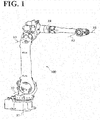
- a robot 100 is a six-axis robot, which includes rotation axes X1 to X6. This configuration, however, is not intended as limiting the number of axes of the robot 100.
- Other examples of the robot 100 include, but are not limited to, a multi-axis robot with seven or more rotation axes, a multi-axis robot with two to five rotation axes, and a single-axis robot.
- the robot 100 is a single-arm robot. In another possible embodiment, the robot 100 may be a multi-arm robot with two or more arms.
- the robot 100 includes a torque sensor 1.
- the torque sensor 1 is disposed in at least one of the rotation axes X1 to X6.
- the torque sensor 1 includes a strain generating body 2 and strain sensors (strain gauges) 10A and 10B.
- the strain sensors 10A and 10B are mounted on a portion of the strain generating body 2.
- the strain generating body 2 generates strain in response to external force, and includes an inner flange 21, an outer flange 22, and a plurality of spokes 23A to 23F.
- the inner flange 21 has a cylindrical shape, as illustrated in FIGs. 2 to 5 .
- the inner flange 21 may have any other shape.
- the outer flange 22 has a ring shape disposed further outward than the inner flange 21 in the radial direction, R, of the inner flange 21. While in this embodiment the outer flange 22 has a ring shape, the outer flange 22 may have any other shape.
- the plurality of spokes 23A to 23F are disposed between the inner flange 21 and the outer flange 22, and connect the inner flange 21 and the outer flange 22 to each other.
- At least one spoke of the plurality of spokes 23A to 23F is a separate spoke which is un-integral to the inner flange 21 and the outer flange 22 and on which the strain sensors 10A and 10B are mounted.
- the spokes 23A and 23B are separate spokes, as illustrated in FIGs. 2 to 7 .
- one of the spokes 23A and 23B may be a separate spoke.
- spokes (separate spokes) 23A and 23B, on which the strain sensors 10A and 10B are mounted are un-integral to the inner flange 21 and the outer flange 22. This configuration facilitates the work of mounting the strain sensors 10A and 10B onto the spokes 23A and 23B.
- all the plurality of spokes 23A to 23F may be un-integral to the inner flange 21 and the outer flange 22.
- the spokes 23A and 23B which are separate spokes in this embodiment, may be designed to bear the load borne by the other spokes 23C to 23F. This design eliminates the need for the other spokes 23C to 23F.
- the plurality of spokes 23A to 23F form a radial pattern between the inner flange 21 and the outer flange 22. This configuration improves productivity and enables cost reduction.
- the plurality of spokes 23A to 23F may form any other pattern between the inner flange 21 and the outer flange 22.
- the spokes 23A and 23B are separate spokes, and the rest of the spokes 23A to 23F, namely, the plurality of spokes 23C to 23F are integral spokes which are integral to the inner flange 21 and the outer flange 22 and on which the strain sensors 10A and 10B are mounted.
- the spokes (integral spokes) 23C to 23F, on which no strain sensors 10A and 10B are mounted, are integral to the inner flange 21 and the outer flange 22. This configuration minimizes the number of the separate spokes, reducing the count of the process steps of forming the strain generating body 2.
- the strain sensors 10A and 10B are mounted on two surfaces 230 and 231 of each of the spokes 23A and 23B, which are separate spokes in this embodiment.
- the two surfaces 230 and 231 are approximately parallel to each other. As used herein, "the two surfaces 230 and 231 are approximately parallel to each other" refers to a level of parallelism between the two surfaces 230 and 231 that is sufficient to secure the advantageous effects of this embodiment.
- each separate spoke (the spokes 23A and 23B) in the circumferential direction, C, of the outer flange 22 is longest between the two surfaces 230 and 231.
- the two surfaces 230 and 231 are most outward portions of the separate spoke (the spokes 23A and 23B) in the circumferential direction C.
- This configuration improves accuracy in grinding and other work involved in such processes as measuring and/or securing the flatness of the two surfaces 230 and 231 and the level of parallelism of the two surfaces 230 and 231, and thickening the two surfaces 230 and 231.
- strain on the separate spoke (the spokes 23A and 23B) is uniformized.
- two strain sensors 10A and 10B are mounted on the surface 230 (corresponding to the first surface recited in the appended claims) of each separate spoke (the spokes 23A and 23B), and another two strain sensors 10A and 10B (corresponding to the two second strain sensors recited in the appended claims) are mounted on the surface 231 (corresponding to the second surface recited in the appended claims) of the separate spoke (the spokes 23A and 23B).
- two strain sensors 10A and 10B are mounted on the two surfaces 230 and 231 of each separate spoke (the spokes 23A and 23B). This configuration improves the strain sensors' reliability of detection of strain.
- the number of the strain sensors mounted on the two surfaces 230 and 231 of the separate spoke will not be limited to two; any other number of strain sensors may be mounted on the two surfaces 230 and 231.
- one strain sensor or a plurality of strain sensors may be mounted on either the surface 230 or the surface 231 of the separate spoke (the spokes 23A and 23B). In this case, any number of strain sensors may be mounted on the surface 230 or the surface 231.
- the number of the strain sensors mounted on the surface 230 may be the same as or different from the number of the strain sensors mounted on the surface 231.
- the number of the strain sensors mounted on the surfaces 230 and 231 of the spoke 23A may be the same as or different from the number of the strain sensors mounted on the surfaces 230 and 231 of the spoke 23B.
- a hole 240 is defined between the two surfaces 230 and 231 of the separate spoke (the spokes 23A and 23B).
- the strain sensors 10A and 10B are mounted on the surfaces 230 and 231. This configuration facilitates the work of mounting the strain sensors 10A and 10B onto the separate spoke (the spokes 23A and 23B). Additionally, the hole 240, which is defined between the two surfaces 230 and 231, uniformizes lateral strain.
- the presence of the hole 240 also enlarges the two surfaces 230 and 231 of the separate spoke (the spokes 23A and 23B) in outer dimensions. This facilitates the means of connection between the separate spoke (the spokes 23A and 23B) and the inner flange 21 and between the separate spoke (the spokes 23A and 23B) and the outer flange 22.
- means as simple as bolts 50 and 51 are used to connect the separate spoke (the spokes 23A and 23B) to the inner flange 21 and the outer flange 22.
- the separate spoke (the spokes 23A and 23B) has thickness T1 .
- the thickness T1 is defined in the circumferential direction C between the hole 240 and the strain sensors 10A and 10B on each of the two surfaces 230 and 231, and is approximately identical to the thickness, T2 , of the integral spoke (the other spokes 23C to 23F) in the circumferential direction C.
- the thickness T1 may not necessarily be uniform throughout the portion defined in the circumferential direction C between the hole 240 and the strain sensors 10A and 10B on each of the two surfaces 230 and 231.
- the thickness T1 may be defined as an average value, a maximum value, or a minimal value of the thicknesses of the portion in the circumferential direction C.
- the thickness T2 may not necessarily be uniform throughout the integral spoke (the other spokes 23C to 23F) in the circumferential direction C.
- the thickness T2 may be defined as an average value, a maximum value, or a minimal value of the thicknesses of the integral spoke (the other spokes 23C to 23F) in the circumferential direction C.
- the above configuration also ensures that once the strain sensors 10A and 10B have detected strain on each of the spokes 23A to 23F, the detected strain is common to each of the spokes 23A to 23F. This, in turn, facilitates the adjustment of a profile of strain caused by external force.
- the hole 240 has a hole dimension of L1 in the circumferential direction C.
- the hole dimension L1 has a first dimension, a second dimension, and a third dimension.
- the first dimension is closer to the inner flange 21 than the strain sensors 10A and 10B are to the inner flange 21.
- the second dimension is closer to the outer flange 22 than the strain sensors 10A and 10B are to the outer flange 22, and is greater than the first dimension.
- the third dimension is closer to the outer flange 22 than the second dimension is to the outer flange 22, and is less than the second dimension.
- This configuration enlarges the region over which strain is uniformized. This, in turn, facilitates the mounting of the strain sensors 10A and 10B.
- the above configuration also enables the separate spoke and the integral spoke identical to each other in dimensions, that is, a common design can be used for the separate spoke and the integral spoke.
- the two strain sensors 10A and 10B overlap each other at least partially in the direction (radial direction, R) in which the two strain sensors 10A and 10B detect strain. Specifically, the two strain sensors 10A and 10B overlap each other in the thickness direction, X , of the separate spoke (the spokes 23A and 23B).
- the thickness direction X is orthogonal to the direction R.
- each of the strain sensors 10A and 10B includes a plurality of wires extending in the radial direction R, in which the two strain sensors 10A and 10B detect strain.
- the wires of the strain sensor 10A and the wires of the strain sensor 10B alternate in the thickness direction X . This arrangement makes the wires of the strain sensors 10A and 10B overlap each other at least partially in the direction R, in which the two strain sensors 10A and 10B detect strain.
- This configuration makes the strain approximately uniform throughout the two strain sensors 10A and 10B, facilitating the multiplexing of the strains detected by the two strain sensors 10A and 10B. As a result, the reliability of the detection of strain by the strain sensors 10A and 10B improves.
- the above configuration also improves the accuracy of measuring the amount by which the side surfaces of the spokes 23A and 23B expand or contract in the radial direction R. This, in turn, improves the accuracy of measuring torque in the circumferential direction C.
- the wires of the strain sensor 10A overlap the wires of the strain sensor 10B in the direction R over substantial region A.
- the wires of the strain sensor 10A overlap the wires of the strain sensor 10B in the direction R over center region B.
- the wires of the strain sensor 10A overlap the wires of the strain sensor 10B in the direction R over the substantial region A within the range of E, which extends in the thickness direction X .
- the wires of the strain sensor 10A do not overlap the wires of the strain sensor 10B in the direction R over the substantial region A within the ranges of C, which extend in the thickness direction X . Instead, it is over regions F that the wires of the strain sensor 10A overlap the wires of the strain sensor 10B in the direction R within the ranges of C, which extend in the thickness direction X .
Landscapes
- Engineering & Computer Science (AREA)
- Robotics (AREA)
- Mechanical Engineering (AREA)
- Physics & Mathematics (AREA)
- General Physics & Mathematics (AREA)
- Human Computer Interaction (AREA)
- Chemical & Material Sciences (AREA)
- Analytical Chemistry (AREA)
- Manipulator (AREA)
- Force Measurement Appropriate To Specific Purposes (AREA)
Abstract
Description
- The present invention relates to a robot and a torque sensor.
- Japanese Unexamined Patent Application Publication No.
2004-029023A1 - The contents of Japanese Unexamined Patent Application Publication No.
2004-029023A1 - With the torque sensor disclosed in Japanese Unexamined Patent Application Publication No.
2004-029023A1 - It is an object of the present disclosure to provide a robot with a torque sensor mounted on the robot without excessive rise in cost of the robot and without adversely affecting the quality of the robot. It is also an object of the present disclosure to provide such torque sensor.
- According to one aspect of the present disclosure, a robot includes a rotation axis and a torque sensor. The torque sensor is disposed on the rotation axis, and includes a strain generating body and a strain sensor. The strain sensor is mounted on a portion of the strain generating body. The strain generating body includes an inner flange, a ring-shaped outer flange, and a plurality of spokes. The outer flange is disposed further outward than the inner flange in a radial direction of the inner flange. The plurality of spokes are disposed between the inner flange and the outer flange and connect the inner flange and the outer flange to each other. At least one spoke of the plurality of spokes is a separate spoke which is un-integral to the inner flange and the outer flange and on which the strain sensor is mounted.
- According to another aspect of the present disclosure, a torque sensor includes a strain generating body and a strain sensor. The strain sensor is mounted on a portion of the strain generating body. The strain generating body includes an inner flange, a ring-shaped outer flange, and a plurality of spokes. The outer flange is disposed further outward than the inner flange in a radial direction of the inner flange. The plurality of spokes are disposed between the inner flange and the outer flange and connect the inner flange and the outer flange to each other. At least one spoke of the plurality of spokes is a separate spoke which is un-integral to the inner flange and the outer flange and on which the strain sensor is mounted.
- The embodiments provide a robot with a torque sensor mounted on the robot without excessive rise in cost of the robot and without adversely affecting the quality of the robot. The embodiments also provide such torque sensor.
- A more complete appreciation of the present disclosure and many of the attendant advantages thereof will be readily obtained as the same becomes better understood by reference to the following detailed description when considered in connection with the accompanying drawings, wherein:
-
FIG. 1 illustrates a robot according to an embodiment; -
FIG. 2 is a plan view of a torque sensor according to the embodiment; -
FIG. 3 is a perspective view of the torque sensor according to the embodiment; -
FIG. 4 is a plan view of the torque sensor with separate spokes removed; -
FIG. 5 is a perspective view of the torque sensor with the separate spokes removed; -
FIG. 6 is a plan view of a separate spoke; -
FIG. 7 is a perspective view of the separate spoke; and -
FIGs. 8A to 8C illustrate exemplary strain sensors mounted on the separate spoke. - An embodiment will be described below by referring to
FIGs. 1 ,2 ,3 ,4 ,5 ,6 ,7 ,8A, 8B, and 8C . As illustrated inFIG. 1 , arobot 100 according to this embodiment is a six-axis robot, which includes rotation axes X1 to X6. This configuration, however, is not intended as limiting the number of axes of therobot 100. Other examples of therobot 100 include, but are not limited to, a multi-axis robot with seven or more rotation axes, a multi-axis robot with two to five rotation axes, and a single-axis robot. Also in the embodiment illustrated inFIG. 1 , therobot 100 is a single-arm robot. In another possible embodiment, therobot 100 may be a multi-arm robot with two or more arms. - The
robot 100 according to this embodiment includes atorque sensor 1. Thetorque sensor 1 is disposed in at least one of the rotation axes X1 to X6. - As illustrated in
FIGs. 2 to 5 , thetorque sensor 1 includes astrain generating body 2 and strain sensors (strain gauges) 10A and 10B. Thestrain sensors strain generating body 2. - The
strain generating body 2 generates strain in response to external force, and includes aninner flange 21, anouter flange 22, and a plurality ofspokes 23A to 23F. - The
inner flange 21 has a cylindrical shape, as illustrated inFIGs. 2 to 5 . Theinner flange 21 may have any other shape. - The
outer flange 22 has a ring shape disposed further outward than theinner flange 21 in the radial direction, R, of theinner flange 21. While in this embodiment theouter flange 22 has a ring shape, theouter flange 22 may have any other shape. - The plurality of
spokes 23A to 23F are disposed between theinner flange 21 and theouter flange 22, and connect theinner flange 21 and theouter flange 22 to each other. - At least one spoke of the plurality of
spokes 23A to 23F is a separate spoke which is un-integral to theinner flange 21 and theouter flange 22 and on which thestrain sensors spokes FIGs. 2 to 7 . In another possible embodiment, one of thespokes - Thus, the spokes (separate spokes) 23A and 23B, on which the
strain sensors inner flange 21 and theouter flange 22. This configuration facilitates the work of mounting thestrain sensors spokes - In another possible embodiment, all the plurality of
spokes 23A to 23F may be un-integral to theinner flange 21 and theouter flange 22. In still another possible embodiment, thespokes other spokes 23C to 23F. This design eliminates the need for theother spokes 23C to 23F. - As illustrated in
FIG. 2 to 5 , the plurality ofspokes 23A to 23F form a radial pattern between theinner flange 21 and theouter flange 22. This configuration improves productivity and enables cost reduction. The plurality ofspokes 23A to 23F may form any other pattern between theinner flange 21 and theouter flange 22. - As illustrated in
FIGs. 2 to 5 , thespokes spokes 23A to 23F, namely, the plurality ofspokes 23C to 23F are integral spokes which are integral to theinner flange 21 and theouter flange 22 and on which thestrain sensors - Thus, the spokes (integral spokes) 23C to 23F, on which no
strain sensors inner flange 21 and theouter flange 22. This configuration minimizes the number of the separate spokes, reducing the count of the process steps of forming thestrain generating body 2. - As illustrated in
FIG. 6 , thestrain sensors surfaces spokes - The two
surfaces surfaces surfaces - Also as illustrated in
FIG. 6 , the outer dimension, L, of each separate spoke (thespokes outer flange 22 is longest between the twosurfaces - This configuration uniformizes strain on the separate spoke (the
spokes - Specifically, the two
surfaces spokes surfaces surfaces surfaces spokes - Additionally, since no other portions of the separate spoke (the
spokes surfaces - As illustrated in
FIGs. 6 and7 , twostrain sensors spokes strain sensors spokes strain sensors surfaces spokes - The number of the strain sensors mounted on the two
surfaces spokes surfaces - In another possible embodiment, one strain sensor or a plurality of strain sensors may be mounted on either the
surface 230 or thesurface 231 of the separate spoke (thespokes surface 230 or thesurface 231. - In still another possible embodiment, on at least one of the
spokes surface 230 may be the same as or different from the number of the strain sensors mounted on thesurface 231. - In still another possible embodiment, the number of the strain sensors mounted on the
surfaces spoke 23A may be the same as or different from the number of the strain sensors mounted on thesurfaces spoke 23B. - A
hole 240 is defined between the twosurfaces spokes - Thus, the
strain sensors surfaces strain sensors spokes hole 240, which is defined between the twosurfaces - The presence of the
hole 240 also enlarges the twosurfaces spokes spokes inner flange 21 and between the separate spoke (thespokes outer flange 22. For example, as illustrated inFIGs. 2 and3 , means as simple asbolts spokes inner flange 21 and theouter flange 22. - The separate spoke (the
spokes hole 240 and thestrain sensors surfaces other spokes 23C to 23F) in the circumferential direction C. - As illustrated in
FIGs. 2 and6 , the thickness T1 may not necessarily be uniform throughout the portion defined in the circumferential direction C between thehole 240 and thestrain sensors surfaces other spokes 23C to 23F) in the circumferential direction C. In this case, the thickness T2 may be defined as an average value, a maximum value, or a minimal value of the thicknesses of the integral spoke (theother spokes 23C to 23F) in the circumferential direction C. - This configuration uniformizes the strain on the separate spoke (the
spokes other spokes 23C to 23F). - The above configuration also ensures that once the
strain sensors spokes 23A to 23F, the detected strain is common to each of thespokes 23A to 23F. This, in turn, facilitates the adjustment of a profile of strain caused by external force. - The
hole 240 has a hole dimension of L1 in the circumferential direction C. The hole dimension L1 has a first dimension, a second dimension, and a third dimension. The first dimension is closer to theinner flange 21 than thestrain sensors inner flange 21. The second dimension is closer to theouter flange 22 than thestrain sensors outer flange 22, and is greater than the first dimension. The third dimension is closer to theouter flange 22 than the second dimension is to theouter flange 22, and is less than the second dimension. - This configuration enlarges the region over which strain is uniformized. This, in turn, facilitates the mounting of the
strain sensors - As illustrated in
FIGs. 8A to 8C , the twostrain sensors strain sensors strain sensors spokes - More specifically, as illustrated in
FIGs. 8A to 8C , each of thestrain sensors strain sensors strain sensor 10A and the wires of thestrain sensor 10B alternate in the thickness direction X. This arrangement makes the wires of thestrain sensors strain sensors - This configuration makes the strain approximately uniform throughout the two
strain sensors strain sensors strain sensors - The above configuration also improves the accuracy of measuring the amount by which the side surfaces of the
spokes - In the embodiment of
FIG. 8A , the wires of thestrain sensor 10A overlap the wires of thestrain sensor 10B in the direction R over substantial region A. - In the embodiment of
FIG 8B , the wires of thestrain sensor 10A overlap the wires of thestrain sensor 10B in the direction R over center region B. - In the embodiment of
FIG. 8C , the wires of thestrain sensor 10A overlap the wires of thestrain sensor 10B in the direction R over the substantial region A within the range of E, which extends in the thickness direction X. - As illustrated in
FIG. 8C , the wires of thestrain sensor 10A do not overlap the wires of thestrain sensor 10B in the direction R over the substantial region A within the ranges of C, which extend in the thickness direction X. Instead, it is over regions F that the wires of thestrain sensor 10A overlap the wires of thestrain sensor 10B in the direction R within the ranges of C, which extend in the thickness direction X. - 100
- Robot
- X1 to X6
- Rotation axis
- 1
- Torque sensor
- 10A, 10B
- Strain sensor
- 2
- Strain generating body
- 21
- Inner flange
- 22
- Outer flange
- 22
- Spoke
- 230,231
- Surface
- 240
- Hole
- C
- Circumferential direction
- R
- Radial direction
- X
- Thickness direction
Claims (10)
- A robot (100), characterized by:a rotation axis (X1 to X6);a torque sensor (1) disposed on the rotation axis (X1 to X6), the torque sensor (1) comprising:a strain generating body (2); anda strain sensor (10A, 10B) mounted on a portion of the strain generating body (2),wherein the strain generating body (2) comprisesan inner flange (21);a ring-shaped outer flange (22) disposed further outward than the inner flange (21) in a radial direction of the inner flange (21); anda plurality of spokes (23A to 23F) disposed between the inner flange (21) and the outer flange (22) and connecting the inner flange (21) and the outer flange (22) to each other, at least one spoke (23A to 23F) of the plurality of spokes (23A to 23F) comprising a separate spoke (23A, 23B) which is un-integral to the inner flange (21) and the outer flange (22) and on which the strain sensor (10A, 10B) is mounted.
- The robot (100) according to claim 1, wherein each of the plurality of spokes (23A to 23F) other than the separate spoke (23A, 23B) comprises an integral spoke (23C to 23F) which is integral to the inner flange (21) and the outer flange (22) and on which the strain sensor (10A, 10B) is not mounted.
- The robot (100) according to claim 1 or 2,
wherein the strain sensor (10A, 10B) comprisesa first strain sensor (10A, 10B) mounted on a first surface (230, 231) of the separate spoke (23A, 23B), anda second strain sensor (10A, 10B) mounted on a second surface (230, 231) of the separate spoke (23A, 23B), the second surface (230, 231) being approximately parallel to the first surface (230, 231), andwherein an outer dimension of the separate spoke (23A, 23B) in a circumferential direction of the outer flange (22) is longest between the first surface (230, 231) and the second surface (230, 231). - The robot (100) according to claim 3, wherein the separate spoke (23A, 23B) comprises a hole (240) disposed between the first surface (230, 231) and the second surface (230, 231).
- The robot (100) according to claim 4, wherein a portion of the separate spoke (23A, 23B) disposed between the strain sensor (10A, 10B) and the hole (240) comprises a thickness in the circumferential direction, the thickness being approximately identical to a thickness of the integral spoke (23C to 23F) in the circumferential direction.
- The robot (100) according to claim 5, wherein the hole (240) comprises a hole dimension (L1) in the circumferential direction, the hole dimension (L1) comprising:a first dimension being closer to the inner flange (21) than the strain sensor (10A, 10B) is to the inner flange (21);a second dimension being closer to the outer flange (22) than the strain sensor (10A, 10B) is to the outer flange (22) and being greater than the first dimension, anda third dimension being closer to the outer flange (22) than the second dimension is to the outer flange (22) and being less than the second dimension.
- The robot (100) according to any one of claims 3 to 6,
wherein the first strain sensor (10A, 10B) comprises two first strain sensors (10A, 10B) mounted on the first surface (230, 231), and
wherein the second strain sensor (10A, 10B) comprises two second strain sensors (10A, 10B) mounted on the second surface (230, 231). - The robot (100) according to claim 7,
wherein the two first strain sensors (10A, 10B) overlap each other at least partially in a direction in which the two first strain sensors (10A, 10B) detect a strain, and
wherein the two second strain sensors (10A, 10B) overlap each other at least partially in a direction in which the two second strain sensors (10A, 10B) detect the strain. - A torque sensor (1), characterized by:a strain generating body (2); anda strain sensor (10A, 10B) mounted on a portion of the strain generating body (2),wherein the strain generating body (2) comprisesan inner flange (21);a ring-shaped outer flange (22) disposed further outward than the inner flange (21) in a radial direction of the inner flange (21); anda plurality of spokes (23A to 23F) disposed between the inner flange (21) and the outer flange (22) and connecting the inner flange (21) and the outer flange (22) to each other, at least one spoke (23A to 23F) of the plurality of spokes (23A to 23F) comprising a separate spoke (23A, 23B) which is un-integral to the inner flange (21) and the outer flange (22) and on which the strain sensor (10A, 10B) is mounted.
- A torque sensor (1), characterized by:a strain generating body (2); anda strain sensor (10A, 10B) mounted on a portion of the strain generating body (2),wherein the strain generating body (2) comprisesan inner flange (21);a ring-shaped outer flange (22) disposed further outward than the inner flange (21) in a radial direction of the inner flange (21); anda plurality of spokes (23A to 23F) disposed between the inner flange (21) and the outer flange (22) and connecting the inner flange (21) and the outer flange (22) to each other, at least one spoke (23A to 23F) of the plurality of spokes (23A to 23F) comprising:two first strain sensors (10A, 10B) mounted on a first surface (230, 231) of the at least one spoke (23A to 23F), the two first strain sensors (10A, 10B) overlapping each other at least partially in a direction in which the two first strain sensors (10A, 10B) detect a strain; andtwo second strain sensors (10A, 10B) mounted on a second surface (230, 231) of the at least one spoke (23A to 23F), the two second strain sensors (10A, 10B) overlapping each other at least partially in a direction in which the two second strain sensors (10A, 10B) detect the strain.
Applications Claiming Priority (1)
| Application Number | Priority Date | Filing Date | Title |
|---|---|---|---|
| JP2016055697A JP2017172983A (en) | 2016-03-18 | 2016-03-18 | Robot and torque sensor |
Publications (2)
| Publication Number | Publication Date |
|---|---|
| EP3219449A2 true EP3219449A2 (en) | 2017-09-20 |
| EP3219449A3 EP3219449A3 (en) | 2017-10-11 |
Family
ID=58387660
Family Applications (1)
| Application Number | Title | Priority Date | Filing Date |
|---|---|---|---|
| EP17161288.0A Withdrawn EP3219449A3 (en) | 2016-03-18 | 2017-03-16 | Robot and torque sensor |
Country Status (3)
| Country | Link |
|---|---|
| US (1) | US20170266814A1 (en) |
| EP (1) | EP3219449A3 (en) |
| JP (1) | JP2017172983A (en) |
Cited By (4)
| Publication number | Priority date | Publication date | Assignee | Title |
|---|---|---|---|---|
| WO2020012764A1 (en) | 2018-07-13 | 2020-01-16 | 日本電産コパル電子株式会社 | Torque sensor |
| EP3779388A4 (en) * | 2018-03-29 | 2021-11-17 | Nidec Copal Electronics Corporation | TORQUE SENSOR |
| EP3779389A4 (en) * | 2018-03-29 | 2021-12-22 | Nidec Copal Electronics Corporation | TORQUE SENSOR |
| EP3819618A4 (en) * | 2018-07-02 | 2022-03-16 | Nidec Copal Electronics Corporation | DEVICE FOR SUPPORTING A TORQUE SENSOR |
Families Citing this family (38)
| Publication number | Priority date | Publication date | Assignee | Title |
|---|---|---|---|---|
| DE202016008595U1 (en) * | 2016-10-17 | 2018-07-26 | Franka Emlka Gmbh | Torque sensor device for detecting torques |
| JP6342971B2 (en) * | 2016-11-14 | 2018-06-13 | ファナック株式会社 | Force detection device and robot |
| JP2018091813A (en) | 2016-12-07 | 2018-06-14 | 日本電産コパル電子株式会社 | Torque sensor |
| JP2018132312A (en) * | 2017-02-13 | 2018-08-23 | 日本電産コパル電子株式会社 | Thin film strain sensor and torque sensor using it |
| JP6980568B2 (en) * | 2018-03-08 | 2021-12-15 | 日本電産コパル電子株式会社 | Torque sensor |
| JP6987676B2 (en) * | 2018-03-08 | 2022-01-05 | 日本電産コパル電子株式会社 | Torque sensor |
| JP7091545B2 (en) * | 2018-03-08 | 2022-06-27 | 日本電産コパル電子株式会社 | Torque sensor |
| JP7062827B2 (en) * | 2018-03-29 | 2022-05-06 | 日本電産コパル電子株式会社 | Torque sensor |
| JP6965197B2 (en) * | 2018-03-29 | 2021-11-10 | 日本電産コパル電子株式会社 | Torque sensor |
| JP7034811B2 (en) * | 2018-04-09 | 2022-03-14 | 日本電産コパル電子株式会社 | Strain sensor fixing device and torque sensor using it |
| KR102072492B1 (en) * | 2018-05-04 | 2020-02-04 | 주식회사 에이엘로봇 | Torque sensor |
| JP6910991B2 (en) | 2018-07-02 | 2021-07-28 | 日本電産コパル電子株式会社 | Torque sensor support device |
| JP7021835B2 (en) * | 2018-07-03 | 2022-02-17 | アズビル株式会社 | Torque sensor |
| JP7059138B2 (en) | 2018-07-13 | 2022-04-25 | 日本電産コパル電子株式会社 | Torque sensor mounting structure |
| CN112513603B (en) | 2018-07-13 | 2022-02-22 | 日本电产科宝电子株式会社 | Mounting structure of torque sensor |
| JP7159072B2 (en) * | 2019-02-07 | 2022-10-24 | 日本電産コパル電子株式会社 | load cell |
| JP7159073B2 (en) * | 2019-02-07 | 2022-10-24 | 日本電産コパル電子株式会社 | load cell |
| JP7187359B2 (en) * | 2019-03-11 | 2022-12-12 | 日本電産コパル電子株式会社 | load cell |
| JP7171476B2 (en) * | 2019-03-11 | 2022-11-15 | 日本電産コパル電子株式会社 | load cell |
| JP7187358B2 (en) * | 2019-03-11 | 2022-12-12 | 日本電産コパル電子株式会社 | load cell |
| JP7350606B2 (en) * | 2019-10-09 | 2023-09-26 | ニデックコンポーネンツ株式会社 | Strain sensor fixing device and torque sensor using it |
| WO2021070665A1 (en) | 2019-10-09 | 2021-04-15 | 日本電産コパル電子株式会社 | Strain-sensor fixing device, and torque sensor using same |
| JP7321872B2 (en) * | 2019-10-09 | 2023-08-07 | ニデックコンポーネンツ株式会社 | Strain sensor fixing device and torque sensor using it |
| JP7321871B2 (en) * | 2019-10-09 | 2023-08-07 | ニデックコンポーネンツ株式会社 | Strain sensor fixing device and torque sensor using it |
| CN114364941A (en) * | 2019-10-09 | 2022-04-15 | 日本电产科宝电子株式会社 | Fixing device of strain sensor and torque sensor using same |
| JP7350605B2 (en) * | 2019-10-09 | 2023-09-26 | ニデックコンポーネンツ株式会社 | Strain sensor fixing device and torque sensor using it |
| JP1667823S (en) * | 2019-11-29 | 2020-09-07 | ||
| JP1667822S (en) * | 2019-11-29 | 2020-09-07 | ||
| GB2597993B (en) * | 2020-08-14 | 2023-05-17 | Dyson Technology Ltd | Torque sensor element and torque sensor |
| CN112665765A (en) * | 2020-12-01 | 2021-04-16 | 哈尔滨工业大学 | Robot high-rigidity joint torque sensor based on parallel load sharing principle |
| JP2022107207A (en) * | 2021-01-08 | 2022-07-21 | 日本電産コパル電子株式会社 | Torque sensor |
| JP7586716B2 (en) * | 2021-01-12 | 2024-11-19 | ミネベアミツミ株式会社 | Drive plate type torque transducer |
| JP2022122340A (en) * | 2021-02-10 | 2022-08-23 | 株式会社レプトリノ | force sensor |
| JP7589091B2 (en) * | 2021-03-31 | 2024-11-25 | ニデックコンポーネンツ株式会社 | Torque Sensor |
| CN117413164A (en) * | 2021-06-30 | 2024-01-16 | 发那科株式会社 | Torque sensor |
| EP4163612A1 (en) * | 2021-10-06 | 2023-04-12 | MEAS France | Sensing membrane for torque sensor device and torque sensor device |
| CN114370916B (en) * | 2021-12-30 | 2024-08-13 | 航天南洋(浙江)科技有限公司 | Spoke type weighing sensor |
| JP7775123B2 (en) | 2022-03-25 | 2025-11-25 | ニデックコンポーネンツ株式会社 | Torque Sensor |
Citations (1)
| Publication number | Priority date | Publication date | Assignee | Title |
|---|---|---|---|---|
| JP2004029023A (en) | 2002-06-25 | 2004-01-29 | Eduard Wille Gmbh & Co Kg | Torque sensor for calibrating screw fastener |
Family Cites Families (10)
| Publication number | Priority date | Publication date | Assignee | Title |
|---|---|---|---|---|
| DE2727704C3 (en) * | 1977-06-21 | 1982-12-09 | Deutsche Forschungs- und Versuchsanstalt für Luft- und Raumfahrt e.V., 5000 Köln | Force-torque sensor |
| JPS6114881A (en) * | 1984-06-26 | 1986-01-23 | 新明和工業株式会社 | Direct drive |
| US4573362A (en) * | 1984-07-09 | 1986-03-04 | Eaton Corporation | Multi-axis load transducer |
| FR2631118B1 (en) * | 1988-05-03 | 1991-08-30 | Onera (Off Nat Aerospatiale) | STRESS SENSOR DEVICE WITH SIX COMPONENTS, ESPECIALLY FOR ROBOTICS |
| DE4133418C2 (en) * | 1991-10-09 | 1993-11-04 | Daimler Benz Ag | MULTI-COMPONENT DISC WHEEL |
| EP1719991A4 (en) * | 2004-02-04 | 2007-04-11 | Ono Sokki Co Ltd | TORQUE MEASURING DEVICE |
| ES2335352T3 (en) * | 2005-09-16 | 2010-03-25 | Abb Ab | AN INDUSTRIAL ROBOT WITH DETECTING MEANS IN THE REGION OF A TOOL FLANGE. |
| CN102317750B (en) * | 2009-02-06 | 2015-07-22 | Abb股份公司 | Set of multiaxial force and torque sensor and assembling method |
| WO2010142318A1 (en) * | 2009-06-08 | 2010-12-16 | Abb Technology Ab | A device for measuring torque |
| WO2014110682A1 (en) * | 2013-01-18 | 2014-07-24 | Robotiq Inc. | Force/torque sensor, apparatus and method for robot teaching and operation |
-
2016
- 2016-03-18 JP JP2016055697A patent/JP2017172983A/en not_active Abandoned
-
2017
- 2017-03-02 US US15/447,132 patent/US20170266814A1/en not_active Abandoned
- 2017-03-16 EP EP17161288.0A patent/EP3219449A3/en not_active Withdrawn
Patent Citations (1)
| Publication number | Priority date | Publication date | Assignee | Title |
|---|---|---|---|---|
| JP2004029023A (en) | 2002-06-25 | 2004-01-29 | Eduard Wille Gmbh & Co Kg | Torque sensor for calibrating screw fastener |
Cited By (7)
| Publication number | Priority date | Publication date | Assignee | Title |
|---|---|---|---|---|
| EP3779388A4 (en) * | 2018-03-29 | 2021-11-17 | Nidec Copal Electronics Corporation | TORQUE SENSOR |
| EP3779389A4 (en) * | 2018-03-29 | 2021-12-22 | Nidec Copal Electronics Corporation | TORQUE SENSOR |
| US11408786B2 (en) | 2018-03-29 | 2022-08-09 | Nidec Copal Electronics Corporation | Torque sensor |
| US11499879B2 (en) | 2018-03-29 | 2022-11-15 | Nidec Copal Electronics Corporation | Torque sensor having a strain sensor |
| EP3819618A4 (en) * | 2018-07-02 | 2022-03-16 | Nidec Copal Electronics Corporation | DEVICE FOR SUPPORTING A TORQUE SENSOR |
| WO2020012764A1 (en) | 2018-07-13 | 2020-01-16 | 日本電産コパル電子株式会社 | Torque sensor |
| US11781927B2 (en) | 2018-07-13 | 2023-10-10 | Nidec Copal Electronics Corporation | Torque sensor |
Also Published As
| Publication number | Publication date |
|---|---|
| JP2017172983A (en) | 2017-09-28 |
| EP3219449A3 (en) | 2017-10-11 |
| US20170266814A1 (en) | 2017-09-21 |
Similar Documents
| Publication | Publication Date | Title |
|---|---|---|
| EP3219449A2 (en) | Robot and torque sensor | |
| US11187600B2 (en) | Torque sensor | |
| US10583570B2 (en) | Displacement measurement device, robot, and robot arm | |
| KR102183179B1 (en) | Multi-axis force-torque sensor using straingauges | |
| JP6615365B2 (en) | Force / torque sensor and method | |
| US9946248B2 (en) | System, robot and robot system for detecting load applied to robot | |
| US11781927B2 (en) | Torque sensor | |
| US10471604B2 (en) | Force detection device and robot | |
| US20130065696A1 (en) | Flexible diaphragm coupling for axial force loading | |
| US11781928B2 (en) | Torque sensor attachment structure | |
| JP6808249B2 (en) | Force sensor | |
| JP2010014695A (en) | Multiaxial sensor | |
| CN106932123B (en) | A kind of wrist sensor | |
| JP7587041B2 (en) | Torque Sensor | |
| TWI796429B (en) | torque sensor | |
| JP7066560B2 (en) | Torque sensor mounting structure | |
| US20080117017A1 (en) | Sensor and manufacturing method thereof | |
| US20230014532A1 (en) | External gear, wave decelerator, and robot | |
| JP7641444B2 (en) | Torque Sensor | |
| KR102012661B1 (en) | Torque sensor | |
| CN114018462B (en) | Force sensor and intelligent equipment | |
| JP7091177B2 (en) | Torque sensor | |
| US20250065513A1 (en) | Force detection device and robot | |
| WO2022209109A1 (en) | Torque sensor | |
| JP2023183228A (en) | torque sensor |
Legal Events
| Date | Code | Title | Description |
|---|---|---|---|
| PUAI | Public reference made under article 153(3) epc to a published international application that has entered the european phase |
Free format text: ORIGINAL CODE: 0009012 |
|
| PUAL | Search report despatched |
Free format text: ORIGINAL CODE: 0009013 |
|
| AK | Designated contracting states |
Kind code of ref document: A2 Designated state(s): AL AT BE BG CH CY CZ DE DK EE ES FI FR GB GR HR HU IE IS IT LI LT LU LV MC MK MT NL NO PL PT RO RS SE SI SK SM TR |
|
| AX | Request for extension of the european patent |
Extension state: BA ME |
|
| AK | Designated contracting states |
Kind code of ref document: A3 Designated state(s): AL AT BE BG CH CY CZ DE DK EE ES FI FR GB GR HR HU IE IS IT LI LT LU LV MC MK MT NL NO PL PT RO RS SE SI SK SM TR |
|
| AX | Request for extension of the european patent |
Extension state: BA ME |
|
| RIC1 | Information provided on ipc code assigned before grant |
Ipc: B25J 13/08 20060101AFI20170907BHEP Ipc: B25J 19/02 20060101ALI20170907BHEP |
|
| STAA | Information on the status of an ep patent application or granted ep patent |
Free format text: STATUS: THE APPLICATION IS DEEMED TO BE WITHDRAWN |
|
| 18D | Application deemed to be withdrawn |
Effective date: 20180412 |