EP3219480A1 - Steuergerät einer rotierenden pressformmaschine - Google Patents
Steuergerät einer rotierenden pressformmaschine Download PDFInfo
- Publication number
- EP3219480A1 EP3219480A1 EP17150773.4A EP17150773A EP3219480A1 EP 3219480 A1 EP3219480 A1 EP 3219480A1 EP 17150773 A EP17150773 A EP 17150773A EP 3219480 A1 EP3219480 A1 EP 3219480A1
- Authority
- EP
- European Patent Office
- Prior art keywords
- molding machine
- punches
- molded product
- turret
- controller
- Prior art date
- Legal status (The legal status is an assumption and is not a legal conclusion. Google has not performed a legal analysis and makes no representation as to the accuracy of the status listed.)
- Granted
Links
Images


Classifications
-
- B—PERFORMING OPERATIONS; TRANSPORTING
- B29—WORKING OF PLASTICS; WORKING OF SUBSTANCES IN A PLASTIC STATE IN GENERAL
- B29C—SHAPING OR JOINING OF PLASTICS; SHAPING OF MATERIAL IN A PLASTIC STATE, NOT OTHERWISE PROVIDED FOR; AFTER-TREATMENT OF THE SHAPED PRODUCTS, e.g. REPAIRING
- B29C43/00—Compression moulding, i.e. applying external pressure to flow the moulding material; Apparatus therefor
- B29C43/32—Component parts, details or accessories; Auxiliary operations
- B29C43/58—Measuring, controlling or regulating
-
- B—PERFORMING OPERATIONS; TRANSPORTING
- B29—WORKING OF PLASTICS; WORKING OF SUBSTANCES IN A PLASTIC STATE IN GENERAL
- B29C—SHAPING OR JOINING OF PLASTICS; SHAPING OF MATERIAL IN A PLASTIC STATE, NOT OTHERWISE PROVIDED FOR; AFTER-TREATMENT OF THE SHAPED PRODUCTS, e.g. REPAIRING
- B29C43/00—Compression moulding, i.e. applying external pressure to flow the moulding material; Apparatus therefor
- B29C43/02—Compression moulding, i.e. applying external pressure to flow the moulding material; Apparatus therefor of articles of definite length, i.e. discrete articles
- B29C43/04—Compression moulding, i.e. applying external pressure to flow the moulding material; Apparatus therefor of articles of definite length, i.e. discrete articles using movable moulds
- B29C43/06—Compression moulding, i.e. applying external pressure to flow the moulding material; Apparatus therefor of articles of definite length, i.e. discrete articles using movable moulds continuously movable in one direction, e.g. mounted on chains, belts
- B29C43/08—Compression moulding, i.e. applying external pressure to flow the moulding material; Apparatus therefor of articles of definite length, i.e. discrete articles using movable moulds continuously movable in one direction, e.g. mounted on chains, belts with circular movement, e.g. mounted on rolls, turntables
-
- B—PERFORMING OPERATIONS; TRANSPORTING
- B30—PRESSES
- B30B—PRESSES IN GENERAL
- B30B11/00—Presses specially adapted for forming shaped articles from material in particulate or plastic state, e.g. briquetting presses, tabletting presses
- B30B11/005—Control arrangements
-
- B—PERFORMING OPERATIONS; TRANSPORTING
- B30—PRESSES
- B30B—PRESSES IN GENERAL
- B30B11/00—Presses specially adapted for forming shaped articles from material in particulate or plastic state, e.g. briquetting presses, tabletting presses
- B30B11/02—Presses specially adapted for forming shaped articles from material in particulate or plastic state, e.g. briquetting presses, tabletting presses using a ram exerting pressure on the material in a moulding space
- B30B11/08—Presses specially adapted for forming shaped articles from material in particulate or plastic state, e.g. briquetting presses, tabletting presses using a ram exerting pressure on the material in a moulding space co-operating with moulds carried by a turntable
-
- B—PERFORMING OPERATIONS; TRANSPORTING
- B30—PRESSES
- B30B—PRESSES IN GENERAL
- B30B15/00—Details of, or accessories for, presses; Auxiliary measures in connection with pressing
- B30B15/26—Program-control arrangements
-
- B—PERFORMING OPERATIONS; TRANSPORTING
- B30—PRESSES
- B30B—PRESSES IN GENERAL
- B30B15/00—Details of, or accessories for, presses; Auxiliary measures in connection with pressing
- B30B15/32—Discharging presses
-
- B—PERFORMING OPERATIONS; TRANSPORTING
- B29—WORKING OF PLASTICS; WORKING OF SUBSTANCES IN A PLASTIC STATE IN GENERAL
- B29C—SHAPING OR JOINING OF PLASTICS; SHAPING OF MATERIAL IN A PLASTIC STATE, NOT OTHERWISE PROVIDED FOR; AFTER-TREATMENT OF THE SHAPED PRODUCTS, e.g. REPAIRING
- B29C43/00—Compression moulding, i.e. applying external pressure to flow the moulding material; Apparatus therefor
- B29C43/32—Component parts, details or accessories; Auxiliary operations
- B29C43/58—Measuring, controlling or regulating
- B29C2043/5833—Measuring, controlling or regulating movement of moulds or mould parts, e.g. opening or closing, actuating
-
- B—PERFORMING OPERATIONS; TRANSPORTING
- B29—WORKING OF PLASTICS; WORKING OF SUBSTANCES IN A PLASTIC STATE IN GENERAL
- B29C—SHAPING OR JOINING OF PLASTICS; SHAPING OF MATERIAL IN A PLASTIC STATE, NOT OTHERWISE PROVIDED FOR; AFTER-TREATMENT OF THE SHAPED PRODUCTS, e.g. REPAIRING
- B29C43/00—Compression moulding, i.e. applying external pressure to flow the moulding material; Apparatus therefor
- B29C43/32—Component parts, details or accessories; Auxiliary operations
- B29C43/58—Measuring, controlling or regulating
- B29C2043/585—Measuring, controlling or regulating detecting defects, e.g. foreign matter between the moulds, inaccurate position, breakage
Definitions
- the invention relates to a controller of a rotary compression molding machine configured to compress a powdery material to mold a pharmaceutical tablet, a food product, an electronic component, or the like.
- a rotary compression molding machine including a table of a turret having die bores, an upper punch and a lower punch slidably retained above and below each of the die bores, and configured to horizontally rotate the die bores and the punches together to compression-mold a powdery material filled in the die bores when the paired upper and lower punches pass between an upper roll and a lower roll (see, for example, JP 2012-110961 A ).
- Each molded product of the compression molding machine is occasionally subjected to post-treatment such as removing a powdery material adhering to the surface, printing or engraving on the surface, or detecting any metal piece erroneously included in the molded product.
- post-treatment is conducted by a peripheral device like a brushing powdery material remover (see, for example, JP 2006-298526 A ), an air jetting powdery material remover (see, for example, JP 2011-245107 A ), a printer (see, for example, JP 2016-010437 A ), or a metal detector (see, for example, " Tablet/capsule metal detector", Acuraks, Inc., (online), 2010, Acuraks, Inc., (searched on February 19, 2016), Internet ⁇ URL: http://www.acuraks.com/products/safeline/safeline_tablex_pro.html> ).
- a peripheral device configured to conduct post-treatment is disposed downstream of a compression molding machine in order for continuous molding to post-treatment of molded products with no interruption, and discharge of the molded products by the molding machine and treatment of the molded products by the peripheral device are different in speed, the molded products can be stuck and overflown at a molded product inlet of the peripheral device.
- tableting speed or speed of compression molding a powdery material by the molding machine influences quality of a molded product of the molding machine. For example, too fast tableting speed is likely to cause capping or separation of the upper or lower end of a molded product, and lamination or layer separation at the intermediate portion of a molded product. In contrast, too slow tableting speed is likely to cause binding or cracking in the side surface of a molded product due to friction with the inner circumferential surface of the die bore, and sticking or adhesion of a separated part of a powdery material for a molded product to the punch end surface.
- the invention has been achieved in view of such problems, and an intended object thereof is to inhibit molded products from being stuck or overflown in a continuous processing system including a rotary compression molding machine and a peripheral device disposed downstream of the molding machine and/or maintain quality of the molded products.
- the invention provides a controller of a rotary compression molding machine configured to rotate a turret including a table having a die bore, and punch retaining portions vertically slidably retaining punches disposed above and below the die bore along with the punches to compress a powdery material filled in the die bore with the punches and obtain a molded product
- the controller being configured to detect, with a sensor, presence and/or an amount of stuck molded products or a flow rate of molded products at an inlet configured to receive a molded product, or at an outlet configured to discharge the molded product subjected to predetermined post-treatment, of a peripheral device disposed downstream of the molding machine and configured to apply the post-treatment to the molded product discharged from the molding machine, and being configured to regulate rotational speed of the turret and the punches of the molding machine in accordance with the detection result, i.e. presence and/or detected amount of the stuck molded products or the detected flow rate of the molded products.
- the controller is configured to reduce the rotational speed of the turret and the punches of the molding machine as the amount of the stuck molded products is larger at the inlet or the outlet of the peripheral device, or reduce the rotational speed of the turret and the punches of the molding machine when the amount of the stuck molded products exceeds a predetermined amount at the inlet or the outlet of the peripheral device in comparison to a case where the amount does not exceed the predetermined amount.
- the invention also provides a controller of a rotary compression molding machine configured to rotate a turret including a table having a die bore, and punch retaining portions vertically slidably retaining punches disposed above and below the die bore along with the punches to compress a powdery material filled in the die bore with the punches and obtain a molded product, the controller being configured to regulate rotational speed of the turret and the punches of the molding machine in accordance with quality of the molded product discharged from the molding machine.
- a powdery material is an aggregate of minute solids and conceptually includes an aggregate of particles such as so-called granules and an aggregate of powder smaller than such particles.
- the invention achieves inhibiting molded products from being stuck or overflown in a continuous processing system including a rotary compression molding machine and a peripheral device disposed downstream of the molding machine and/or maintaining quality of the molded products.
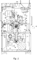
- the molding machine A has a frame 1 including an upright shaft 2 functioning as a rotary shaft, and a turret 3 is attached to a connection portion 21 that is disposed at the top of the upright shaft 2.
- the turret 3 horizontally rotates about the upright shaft 2, more specifically, spins.
- the turret 3 includes a table (die disc) 31, an upper punch retaining portion 32, and a lower punch retaining portion 33.
- the table 31 has a substantially circular disc shape, and a plurality of die bores 4 is formed in an outer circumferential portion thereof so as to be aligned in a direction of rotation and be spaced apart from each other at predetermined intervals.
- the die bores 4 each penetrate the table 31 in the vertical direction.
- the table 31 may be composed of a plurality of divided plates.
- the table 31 alternatively has a plurality of die members that is separate from the table 31 and is detachably attached thereto.
- each of the die members alternatively has a die bore penetrating in the vertical direction.
- An upper punch 5 and a lower punch 6 are disposed above and below each of the die bores 4.
- the upper punches 5 and the lower punches 6 are retained by the upper punch retaining portion 32 and the lower punch retaining portion 33 so as to be independently slidable in the vertical direction in the die bores 4.
- the upper punches 5 each have a tip 53 that enters and exits corresponding one of the die bores 4.
- the lower punches 6 each have a tip 63 that is always inserted in corresponding one of the die bores 4.
- the upper punches 5 and the lower punches 6 horizontally rotate, more specifically revolve, about the upright shaft 2 along with the turret 3 and the die bores 4.
- the upright shaft 2 has the lower end to which a worm wheel 7 is attached.
- the worm wheel 7 meshes with a worm gear 10.
- the worm gear 10 is fixed to a gear shaft 9 that is driven by a motor 8.
- Drive power outputted from the motor 8 is transmitted to the gear shaft 9 by way of a belt 11, so as to drive to rotate the upright shaft 2 by way of the worm gear 10 and the worm wheel 7, and further to rotate the turret 3 and the punches 5 and 6.
- a powdery material or a raw material for a compression molded product such as a pharmaceutical tablet is filled in the die bores 4 via a feeder X.
- the feeder X can be of either one of types, namely, an agitated feeder and a gravity feeder.
- the powdery material is fed to the feeder X with use of a powdery material feeding device.
- the powdery material is fed to the powdery material feeding device via a hopper 19.
- the hopper 19 is detachably attached to the molding machine A.
- a preliminary compression upper roll 12, a preliminary compression lower roll 13, a substantial compression upper roll 14, and a substantial compression lower roll 15 are disposed on orbits of the punches 5 and 6 that revolve about the upright shaft 2.
- the preliminary compression upper roll 12 and the preliminary compression lower roll 13, as well as the substantial compression upper roll 14 and the substantial compression lower roll 15, are respectively paired in the vertical direction so as to sandwich the punches 5 and 6.
- the upper and lower punches 5 and 6 have heads 51 and 61 pressed by the rolls 12, 13, 14, and 15, and trunks 52 and 62 smaller in diameter than the heads 51 and 61.
- the upper punch retaining portion 32 of the turret 3 vertically slidably retains the trunks 52 of the upper punches 5, whereas the lower punch retaining portion 33 vertically slidably retains the trunks 62 of the lower punches 6.
- the tips 53 and 63 of the trunks 52 and 62 are thinner than the remaining portions and are substantially equal in diameter to the inner diameter of the die bores 4 so as to be inserted to the die bores 4.
- Revolution of the punches 5 and 6 causes the rolls 12, 13, 14, and 15 to be come close to the heads 51 and 61 of the punches 5 and 6 and step onto and contact the heads 51 and 61.
- the rolls 12, 13, 14, and 15 further press the upper punches 5 downward and press the lower punches 6 upward. While the rolls 12, 13, 14, and 15 are in contact with flat top surfaces of the punches 5 and 6, the punches 5 and 6 keep applying constant pressure to the powdery material in the corresponding die bore 4.
- a molded product unloading portion 16 is provided ahead, in the direction of rotation of the turret 3 and the punches 5 and 6, of the position where the substantial compression upper roll 14 and the substantial compression lower roll 15 apply pressure.
- the lower punch 6 ascends until the upper end surface of the tip 63 of the lower punch 6 reaches the height substantially same as that of the upper end of the die bore 4, in other words, the upper surface of the table 31.
- the lower punch 6 then pushes the molded product out of the die bore 4.
- the molded product unloading portion 16 has a guide member 17 that guides the molded product pushed out of the die bore 4.
- the molded product extracted from the die bore 4 is brought into contact with the guide member 17 due to the rotation of the turret 3, and is shifted along the guide member 17 toward a molded products collecting position 18.
- peripheral devices B to F configured to apply post-treatment to a molded product is disposed downstream of the molding machine A according to the embodiment, to conduct continuously, with no interruption, production of a molded product by the molding machine A and post-treatment by the peripheral device B, C, D, E, or F.
- post-treatment include removing a powdery material adhering to the surface of a molded product, detecting any metal piece erroneously included in a molded product, printing or engraving on the surface of a molded product, checking at least one of properties such as weight, thickness, density, hardness, outer appearance, and composition of a molded product.
- peripheral devices B to F that are configured to conduct such post-treatment and are disposed downstream of the molding machine A configured to produce a molded product include a powdery material remover, a metal detector, a printer, an engraving device, and a molded product property checker.
- Fig. 4 exemplifies a powdery material remover B, a metal detector C, a lift D, a printer E, and an checker F, which are disposed downstream of the molding machine A and are aligned in the mentioned order. These peripheral devices B to F are well known.
- the powdery material remover B receives, at an inlet B1, a molded product dropped at the molded products collecting position 18 of the molding machine A, removes a powdery material adhering to the surface of the received molded product, and discharges the molded product at an outlet B2.
- the powdery material remover B scrapes a powdery material on the surface of the molded product with an incorporated brush, or removes the powdery material on the surface of the molded product with sprayed air.
- the metal detector C receives, at an inlet C1, the molded product dropped from the outlet B2 of the powdery material remover B, detects any metal piece erroneously included in the received molded product, and discharges, at an outlet C2, the molded product including no metal piece.
- the lift D receives, at an inlet D1, the molded product dropped from the outlet C2 of the metal detector C, lifts the received molded product upward, and discharges, at an outlet D2 located at a higher level than the inlet D1, the molded product.
- the lift D can be configured to blow, with air, the molded product upward from the inlet D1 to the outlet D2, or can include a mechanical convey mechanism configured to convey the molded product from the inlet D1 to the outlet D2 with a bucket lifter, a belt conveyer, or a member reciprocating in a path.
- the printer E receives, at an inlet E1, the molded product dropped from the outlet D2 of the lift D, prints or engraves on the surface of the received molded product, and discharges the molded product at an outlet E2.
- the printer E can be configured to irradiate the surface of the molded product with laser light or the like to color or carve the surface of the molded product, or can be an ink jet printer configured to apply pigment to the surface of the molded product.
- the checker F receives, at an inlet F1, the molded product discharged from the outlet E2 of the printer E, checks at least one of properties such as weight, thickness, density, hardness, outer appearance, and composition of the received molded product, and discharges the checked molded product at an outlet F2.
- the checker F can be configured to check the properties of the molded product in accordance with any appropriate specific manner, and can have any one of various known modes.
- At least one of the inlets B1 to F1 or the outlets B2 to F2 of the peripheral devices B to F has a sensor 7 configured to detect an amount of molded products stuck at the corresponding one of the inlets B1 to F1 and the outlets B2 to F2.
- the sensor 7 can be a contact sensor configured to contact to sense a molded product so as to detect an amount of stuck molded products, or can be a contactless sensor configured to irradiate the molded product with an infrared wave, a different light wave, or an electromagnetic wave to sense the molded product and detect the amount of stuck molded products.
- the senor 7 can be a gravimetric sensor configured to measure weight of molded products stuck at the corresponding one of the inlets B1 to F1 and the outlets B2 to F2 to detect the amount of the stuck molded products. In other words, the sensor 7 can determine whether or not there are any molded products which are stuck in the processing line.
- a controller 0 of the molding machine A is configured to control operation of the molding machine A.
- the controller 0 include a programmable controller, as well as a microcomputer system, a personal computer, and a work station each of which includes a processor, a memory, an auxiliary storage device (e.g. a flash memory), an input/output interface, and the like.
- the controller 0 reads a program preliminarily stored in the auxiliary storage device to the processor by way of the memory, causes the processor to decode the program, and controls the molding machine A.
- the controller 0 refers to the amount of stuck molded products of at least one of the inlets B1 to F1 or the outlets B2 to F2 of the peripheral devices B to F detected by the sensor 7, and reduces rotational speed of the turret 3 and the punches 5 and 6 of the molding machine A, i.e. rotational speed of the motor 8, as the amount of the stuck molded products becomes larger and/or is larger than a predetermined value.
- the controller 0 alternatively reduces rotational speed of the turret 3 and the punches 5 and 6 of the molding machine A if the amount of stuck molded products exceeds a predetermined amount, from rotational speed in a case where the detected amount is not more than the predetermined amount.
- the controller 0 is preferably configured to refer to the largest one of amounts of stuck molded products detected by the sensors 7.
- any of the peripheral devices B to F fails to smoothly conduct post-treatment or is fed with an excessive amount of molded products for capacity or speed of the post-treatment by the peripheral devices B to F and molded products are stuck at corresponding one of the inlets B1 to F1 and the outlets B2 to F2 of the peripheral devices B to F
- such control reduces rotational speed of the molding machine A configured to discharge molded products to reduce the amount of molded products to be fed to the peripheral devices B to F per unit time.
- the control thus effectively prevents molded products from being overflown at corresponding one of the inlets B 1 to F1 and the outlets B2 to F2 of the peripheral devices B to F.
- the controller 0 normally keeps rotation of the turret 3 and the punches 5 and 6 of the molding machine A even in a case where the sensor 7 detects stuck molded products at any of the inlets B 1 to F 1 and the outlets B2 to F2 of the peripheral devices B to F.
- the controller 0 simply reduces rotational speed of the turret 3 and the punches 5 and 6 and normally keeps operation of the molding machine A even when molded products are stuck at any of the inlets B1 to F1 and the outlets B2 to F2 of the peripheral devices B to F.
- the controller 0 reduces rotational speed of the turret 3 and the punches 5 and 6 of the molding machine A to be lower than ordinary or normal speed in accordance with the amount of stuck molded products, the controller 0 recovers the rotational speed of the turret 3 and the punches 5 and 6 to the ordinary or normal speed if the amount of the stuck molded products detected by the sensor 7 becomes not more than the predetermined amount within a predetermined period from the reduction in speed.
- the controller 0 can exceptionally stop rotation of the turret 3 and the punches 5 and 6, in other words, stop the molding machine A, to cope with such emergency.
- the controller 0 can be configured to increase rotational speed of the turret 3 and the punches 5 and 6 of the molding machine A to be higher than the ordinary or normal speed.
- the controller 0 can alternatively be configured to increase rotational speed of the turret 3 and the punches 5 and 6 as the amount of stuck molded products detected by the sensor 7 becomes smaller. Such control achieves further increase in amount of produced molded products.
- the controller 0 is configured to regulate rotational speed of the turret 3 and the punches 5 and 6 in accordance with quality of a molded product discharged from the molding machine A.
- the controller 0 finds defective quality of a molded product discharged from the molding machine A due to fast rotational speed of the turret 3 and the punches 5 and 6, in other words, fast tableting speed of the molding machine A (and the quality is expected to be improved by reduction in tableting speed)
- the controller 0 reduces the rotational speed of the turret 3 and the punches 5 and 6 by reducing rotational speed of the motor 8 of the molding machine A.
- the controller 0 reduces current rotational speed of the turret 3 and the punches 5 and 6 to extend a period of pressing the powdery material in the die bores 4 by the punches 5 and 6 so as to correct density or hardness of molded products or prevent capping or lamination.
- the controller 0 increases rotational speed of the turret 3 and the punches 5 and 6 by increasing rotational speed of the motor 8 of the molding machine A.
- the controller 0 increases current rotational speed of the turret 3 and the punches 5 and 6 to shorten the period of pressing the powdery material in the die bores 4 by the punches 5 and 6 so as to correct density or hardness of molded products or prevent binding or sticking.
- the controller 0 When the controller 0 reduces rotational speed of the turret 3 and the punches 5 and 6 of the molding machine A to be lower than the ordinary or normal speed in accordance with defective quality of a molded product, the controller 0 recovers the rotational speed of the turret 3 and the punches 5 and 6 to the ordinary or normal speed if quality of a molded product is improved within a predetermined period from the reduction in speed.
- the controller 0 increases rotational speed of the turret 3 and the punches 5 and 6 to be higher than the ordinary or normal speed but quality of a molded product is improved within the predetermined period from the increase in speed, the controller 0 reduces the rotational speed of the turret 3 and the punches 5 and 6 to the ordinary or normal speed. If quality of a molded product is not improved after the predetermined period from reduction or increase in rotational speed of the turret 3 and the punches 5 and 6, the controller 0 can exceptionally stop rotation of the turret 3 and the punches 5 and 6, in other words, stop the molding machine A, to cope with such emergency.
- the controller 0 can alternatively increase rotational speed of the turret 3 and the punches 5 and 6 of the molding machine A while molded products have no quality defect and reduce the rotational speed of the turret 3 and the punches 5 and 6 upon sensing defective quality of a molded product.
- the embodiment provides a controller 0 of a rotary compression molding machine A configured to rotate a turret 3 including a table 31 having a die bore 4, and punch retaining portions 32 and 33 vertically slidably retaining punches 5 and 6 disposed above and below the die bore 4 along with the punches 5 and 6 to compress a powdery material filled in the die bore 4 with the punches 5 and 6 and obtain a molded product.
- the controller 0 is configured to detect an amount of stuck molded products at an inlet B1, C1, D1, E1, or F1 configured to receive a molded product or an outlet B2, C2, D2, E2, or F2 configured to discharge the molded product subjected to predetermined post-treatment, of a peripheral device B, C, D, E, or F disposed downstream of the molding machine A and configured to apply the post-treatment to the molded product discharged from the molding machine A, and regulate rotational speed of the turret 3 and the punches 5 and 6 of the molding machine A in accordance with the detected amount of the stuck molded products.
- the embodiment achieves inhibiting molded products from being stuck or overflown in a continuous processing system including the rotary compression molding machine A and the peripheral device B, C, D, E, or F disposed downstream of the molding machine A.
- the embodiment also provides a controller 0 of a rotary compression molding machine A configured to rotate a turret 3 including a table 31 having a die bore 4, and punch retaining portions 32 and 33 vertically slidably retaining punches 5 and 6 disposed above and below the die bore 4 along with the punches 5 and 6 to compress a powdery material filled in the die bore 4 with the punches 5 and 6 and obtain a molded product.
- the controller 0 is configured to regulate rotational speed of the turret 3 and the punches 5 and 6 of the molding machine A in accordance with quality of the molded product discharged from the molding machine A.
- the embodiment achieves maintaining quality of the molded product fed from the molding machine A in the continuous processing system including the rotary compression molding machine A and the peripheral device B, C, D, E, or F disposed downstream of the molding machine A.
- the controller feedback-controls the rotational speed of the molding machine A based on the quality which is checked in the post-treatment.
- the controller 0 normally keeps operation of the molding machine A even when molded products are stuck at the inlet B1, C1, D1, E1, or F1 or the outlet B2, C2, D2, E2, or F2 of the peripheral device B, C, D, E, or F or a molded product has defective quality.
- the controller 0 is configured to reduce loss of molded products that would be caused for a certain period right after restart of the molding machine A.
- the peripheral devices B to F disposed downstream of the rotary compression molding machine A are not limited in type and number to those shown in Fig. 4 .
- the system does not need to include the powdery material remover.
- the system does not need to include the printer if a molded product is appropriately engraved on the surface while the molded product is compression molded by the punches of the molding machine A and printing or engraving does not need to be applied afterward to the molded product discharged from the molding machine A.
- the checker F configured to check a property of a molded product or the like may not be disposed downstream of the molding machine A.
- At least one of the inlets B1 to F1 or the outlets B2 to F2 of the peripheral devices B to F may have a sensor 7 configured to detect a flow rate of molded products, i.e. count the number of the molded products per unit time, at a corresponding one of the inlets B 1 to F 1 and the outlets B2 to F2, and the controller 0 may be configured to regulate rotational speed of the turret 3 and the punches 5 and 6 of the molding machine A in accordance with the flow rate of the molded products detected by the sensor 7. In this case, the rotational speed of the turret 3 and the punches 5 and 6 of the molding machine A, i.e.
- the controller 0 reduces the rotational speed of the turret 3 and the punches 5 and 6 in comparison to the case where the flow rate does not exceed the predetermined value.
- the controller 0 is preferably configured to refer to the largest one of the flow rates of molded products detected by the sensors 7.
- the controller 0 is also preferred to regulate the rotational speed of the turret 3 and the punches 5 and 6 of the molding machine A in accordance with numerical comparison between a flow rate of molded products discharged from the molding machine A, i.e. the number of molded products produced by the molding machine A per unit time, and a flow rate of molded products at any of the inlets B 1 to F1 and the outlets B2 to F2 of the peripheral devices B to F.
- the upper rolls 12 and 14 of the molding machine A each have a load cell 20 configured to detect pressure applied to compress the powdery material in the die bore 4 by the rolls 12 to 15 via the punches 5 and 6.
- the controller 0 receives a signal transmitted from the load cell 20 at each of the rolls 12 to 15 to find magnitude of pressure applied to compress the powdery material by the preliminarily compression rolls 12 and 13 (preliminary compression pressure) and magnitude of pressure applied to compress the powdery material by the substantial compression rolls 14 and 15 (substantial compression pressure).
- Signals outputted from each of the load cells 20 form a pulse signal train having a peak when each of the pairs of punches 5 and 6 compresses the powdery material in corresponding one of the die bores 4 with maximum pressure.
- the controller 0 thus counts the number of pulse trains to find the number of molded products produced by the molding machine A per unit time.
- the controller 0 increases or reduces the rotational speed of the turret 3 and the punches 5 and 6 to reduce the difference. Specifically, the controller 0 reduces the rotational speed of the turret 3 and the punches 5 and 6 if the former value is more than the latter value, and increases the rotational speed of the turret 3 and the punches 5 and 6 if the former value is less than the latter value.
- a device other than the checker F, particularly the molding machine A itself, can be configured to detect any quality defect of a molded product.
- the molding machine A includes a camera sensor or the like, which is disposed in a region between the molded product unloading portion 16 and the feeder X and is configured to detect a state of the inner circumferential surface of the die bore 4, the lower end surface of the punch 5, or the upper end surface of the punch 6.
- the controller 0 analyzes an image captured by the camera sensor being a contactless sensor, of the inner circumferential surface of the die bore 4 or the end surface of the punch 5 or 6 to check whether or not a powdery material adheres to the inner circumferential surface of the die bore 4 or the end surface of the punch 5 or 6, i.e. whether or not a molded product is partially cracked due to binding or sticking.
- the controller 0, which has found binding or sticking in such a manner, increases or reduces current rotational speed of the turret 3 and the punches 5 and 6 to inhibit binding and sticking.
- the controller 0 can be configured to control rotational speed of the turret 3 and the punches 5 and 6 as well as rotational speed of the agitating rotor.
- the controller 0 thus configured increases the rotational speed of (a motor configured to drive) the agitating rotor of the agitated feeder X as the rotational speed of the turret 3 and the punches 5 and 6 increases.
- the controller 0 increases rotational speed of the agitating rotor if the turret 3 and the punches 5 and 6 have high rotational speed, in comparison to a case where the turret 3 and the punches 5 and 6 have lower rotational speed.
- the controller 0 can be configured to control processing speed of the peripheral devices B to F (particularly the printer E that is likely to cause molded products to be stuck), as well as control rotational speed of the turret 3 and the punches 5 and 6 of the molding machine A. Specifically, the controller 0 increases speed of post-treatment by the peripheral devices B to F as the turret 3 and the punches 5 and 6 have higher rotational speed. Alternatively, the controller 0 increases processing speed of the peripheral devices B to F if the turret 3 and the punches 5 and 6 have high rotational speed, in comparison to a case where the turret 3 and the punches 5 and 6 have lower rotational speed.
Landscapes
- Engineering & Computer Science (AREA)
- Mechanical Engineering (AREA)
- Medical Preparation Storing Or Oral Administration Devices (AREA)
- Presses And Accessory Devices Thereof (AREA)
- Press Drives And Press Lines (AREA)
Applications Claiming Priority (1)
| Application Number | Priority Date | Filing Date | Title |
|---|---|---|---|
| JP2016052950A JP6681756B2 (ja) | 2016-03-16 | 2016-03-16 | 回転式粉体圧縮成形機の制御装置 |
Publications (2)
| Publication Number | Publication Date |
|---|---|
| EP3219480A1 true EP3219480A1 (de) | 2017-09-20 |
| EP3219480B1 EP3219480B1 (de) | 2024-08-21 |
Family
ID=57777522
Family Applications (1)
| Application Number | Title | Priority Date | Filing Date |
|---|---|---|---|
| EP17150773.4A Active EP3219480B1 (de) | 2016-03-16 | 2017-01-10 | Steuergerät einer rotierenden pressformmaschine |
Country Status (3)
| Country | Link |
|---|---|
| US (1) | US10525618B2 (de) |
| EP (1) | EP3219480B1 (de) |
| JP (1) | JP6681756B2 (de) |
Families Citing this family (8)
| Publication number | Priority date | Publication date | Assignee | Title |
|---|---|---|---|---|
| JP6883316B2 (ja) | 2017-02-15 | 2021-06-09 | 株式会社菊水製作所 | 粉体供給装置及び粉体供給方法 |
| JP6857896B2 (ja) * | 2017-03-16 | 2021-04-14 | 株式会社菊水製作所 | 粉体供給装置 |
| JP2018205099A (ja) * | 2017-06-02 | 2018-12-27 | コニカミノルタ株式会社 | 筒状物の検査装置 |
| JP7224612B2 (ja) | 2017-10-06 | 2023-02-20 | 株式会社菊水製作所 | 成形品処理システム |
| JP7031850B2 (ja) | 2017-12-25 | 2022-03-08 | 株式会社菊水製作所 | 成形品搬送装置 |
| JP7152006B2 (ja) * | 2018-09-27 | 2022-10-12 | 株式会社菊水製作所 | 成形品生産システム |
| JP2021000647A (ja) * | 2019-06-20 | 2021-01-07 | 株式会社菊水製作所 | 回転式粉体圧縮成形機の制御装置及び制御方法 |
| JP7816767B2 (ja) * | 2022-07-25 | 2026-02-18 | 株式会社菊水製作所 | 回転式粉体圧縮成形機の制御装置 |
Citations (10)
| Publication number | Priority date | Publication date | Assignee | Title |
|---|---|---|---|---|
| WO1998012517A1 (en) * | 1996-09-18 | 1998-03-26 | Unimetal Co., Ltd. | Apparatus and method for controlling weight of solid material |
| JP2920128B1 (ja) * | 1998-01-08 | 1999-07-19 | 株式会社畑鉄工所 | 回転式粉末圧縮成型機 |
| EP1568480A2 (de) * | 2004-02-20 | 2005-08-31 | Fette GmbH | Verfahren und Vorrichtung zur Qualitätsüberwachung bei der Herstellung von Tabletten |
| JP2006298526A (ja) | 2005-04-18 | 2006-11-02 | Nippon Kosan Kk | 錠剤粉取装置 |
| EP2036707A2 (de) * | 2007-09-13 | 2009-03-18 | Fette GmbH | Optische Überwachungsvorrichtung für Rundlaufpressen |
| US20100078841A1 (en) * | 2008-09-25 | 2010-04-01 | Fette Gmbh | Method for quality surveillance of powdered pressed material and a rotary press for performing the method |
| JP2011245107A (ja) | 2010-05-28 | 2011-12-08 | Nippon Kosan Kk | 固形物の除粉装置 |
| JP2012110961A (ja) | 2010-11-29 | 2012-06-14 | Kikusui Seisakusho Ltd | 粉体圧縮成形機 |
| JP2014221343A (ja) * | 2014-06-23 | 2014-11-27 | ジーイーエイ・ファーマ・システムズ・リミテッド | 錠剤の製造モジュール及び錠剤の連続製造方法 |
| JP2016010437A (ja) | 2014-06-27 | 2016-01-21 | 株式会社Screenホールディングス | 錠剤印刷装置および錠剤印刷方法 |
Family Cites Families (6)
| Publication number | Priority date | Publication date | Assignee | Title |
|---|---|---|---|---|
| JPH0522398Y2 (de) * | 1989-04-28 | 1993-06-08 | ||
| US5085515A (en) * | 1990-02-08 | 1992-02-04 | Mitsubishi Metal Corporation | Method and apparatus for inspecting quality of manufactured articles |
| EP1791628A4 (de) * | 2004-09-21 | 2011-09-28 | Glaxo Group Ltd | Mischsystem und -verfahren |
| EP2427166B1 (de) * | 2009-05-07 | 2013-10-16 | Gea Pharma Systems Limited | Tablettenproduktionsmodul und verfahren zur kontinuierlichen herstellung von tabletten |
| DE202015107010U1 (de) * | 2015-12-22 | 2016-01-22 | Korsch Ag | Machinensteuerung für eine Tablettiermaschine |
| DE102018116143B4 (de) * | 2018-07-04 | 2020-08-20 | Fette Compacting Gmbh | Weiche eines Tablettenablaufs einer Tablettenpresse sowie Verfahren zum Betätigen einer Weiche |
-
2016
- 2016-03-16 JP JP2016052950A patent/JP6681756B2/ja active Active
-
2017
- 2017-01-10 EP EP17150773.4A patent/EP3219480B1/de active Active
- 2017-02-17 US US15/436,477 patent/US10525618B2/en active Active
Patent Citations (10)
| Publication number | Priority date | Publication date | Assignee | Title |
|---|---|---|---|---|
| WO1998012517A1 (en) * | 1996-09-18 | 1998-03-26 | Unimetal Co., Ltd. | Apparatus and method for controlling weight of solid material |
| JP2920128B1 (ja) * | 1998-01-08 | 1999-07-19 | 株式会社畑鉄工所 | 回転式粉末圧縮成型機 |
| EP1568480A2 (de) * | 2004-02-20 | 2005-08-31 | Fette GmbH | Verfahren und Vorrichtung zur Qualitätsüberwachung bei der Herstellung von Tabletten |
| JP2006298526A (ja) | 2005-04-18 | 2006-11-02 | Nippon Kosan Kk | 錠剤粉取装置 |
| EP2036707A2 (de) * | 2007-09-13 | 2009-03-18 | Fette GmbH | Optische Überwachungsvorrichtung für Rundlaufpressen |
| US20100078841A1 (en) * | 2008-09-25 | 2010-04-01 | Fette Gmbh | Method for quality surveillance of powdered pressed material and a rotary press for performing the method |
| JP2011245107A (ja) | 2010-05-28 | 2011-12-08 | Nippon Kosan Kk | 固形物の除粉装置 |
| JP2012110961A (ja) | 2010-11-29 | 2012-06-14 | Kikusui Seisakusho Ltd | 粉体圧縮成形機 |
| JP2014221343A (ja) * | 2014-06-23 | 2014-11-27 | ジーイーエイ・ファーマ・システムズ・リミテッド | 錠剤の製造モジュール及び錠剤の連続製造方法 |
| JP2016010437A (ja) | 2014-06-27 | 2016-01-21 | 株式会社Screenホールディングス | 錠剤印刷装置および錠剤印刷方法 |
Non-Patent Citations (1)
| Title |
|---|
| "Tablet/capsule metal detector", 2010, ACURAKS, INC. |
Also Published As
| Publication number | Publication date |
|---|---|
| US10525618B2 (en) | 2020-01-07 |
| US20170266853A1 (en) | 2017-09-21 |
| JP2017164786A (ja) | 2017-09-21 |
| JP6681756B2 (ja) | 2020-04-15 |
| EP3219480B1 (de) | 2024-08-21 |
Similar Documents
| Publication | Publication Date | Title |
|---|---|---|
| EP3219480B1 (de) | Steuergerät einer rotierenden pressformmaschine | |
| CN102803079B (zh) | 连续回转式填充包装机械以及密封容器制造方法 | |
| EP2239133B1 (de) | Rotierende Pulverformpressmaschine und Verfahren zum Prüfen die Aussortierung des Presslinges | |
| JP7224612B2 (ja) | 成形品処理システム | |
| EP3335868B1 (de) | Steuergerät und steuerungsverfahren für eine rotierende pressformmaschine | |
| EP3505341B1 (de) | Steuergerät und steuerungsverfahren | |
| KR101772368B1 (ko) | 정제를 분류하기 위한 개체 분류 장치, 그러한 개체 분류 장치 및 정제형성 장치를 갖는 시스템, 및 개체 분류 장치를 점검하기 위한 방법 | |
| US10513073B2 (en) | Scraping device for a rotary press, rotary press, and method for operating a rotary press | |
| Bogda | Tablet compression: Machine theory, design and process troubleshooting | |
| EP3175976B1 (de) | Ausgabevorrichtung eines geformten produkts | |
| CN209112555U (zh) | 一种纸箱高速赋码标识装置 | |
| US10641669B2 (en) | Device and method for determining a closing force during the closure of a capsule | |
| JP2016532561A (ja) | 粉体圧縮方法およびローラ型圧縮装置 | |
| JP7816767B2 (ja) | 回転式粉体圧縮成形機の制御装置 | |
| KR101368202B1 (ko) | 견과류 탈피장치 | |
| EP3501812A1 (de) | Fördervorrichtung für geformte produkte | |
| CN216728312U (zh) | 罐体无码检测装置 | |
| CN109277312B (zh) | 一种理坯、瓶坯口照相检测一体机构 | |
| EP4691750A1 (de) | Inspektionsvorrichtung für eine maschine zur herstellung von geformten produkten | |
| EP4647248A1 (de) | Überwachungssystem für eine formproduktherstellungsmaschine | |
| CN105235388B (zh) | 一种炸药药箱连续化数字印码的设备和方法 | |
| EP4443129A1 (de) | System und verfahren zur messung der härte eines formprodukts | |
| CN223619087U (zh) | 一种用于泡罩包装机的自动检测装置 | |
| CN218798817U (zh) | 切筋装置及功率器件 | |
| EP2251101A2 (de) | Vorrichtung zum selektiven Aufrichten, insbesondere für Kunststoffbehältnisse wie Flaschen |
Legal Events
| Date | Code | Title | Description |
|---|---|---|---|
| PUAI | Public reference made under article 153(3) epc to a published international application that has entered the european phase |
Free format text: ORIGINAL CODE: 0009012 |
|
| STAA | Information on the status of an ep patent application or granted ep patent |
Free format text: STATUS: THE APPLICATION HAS BEEN PUBLISHED |
|
| AK | Designated contracting states |
Kind code of ref document: A1 Designated state(s): AL AT BE BG CH CY CZ DE DK EE ES FI FR GB GR HR HU IE IS IT LI LT LU LV MC MK MT NL NO PL PT RO RS SE SI SK SM TR |
|
| AX | Request for extension of the european patent |
Extension state: BA ME |
|
| STAA | Information on the status of an ep patent application or granted ep patent |
Free format text: STATUS: REQUEST FOR EXAMINATION WAS MADE |
|
| 17P | Request for examination filed |
Effective date: 20180226 |
|
| RBV | Designated contracting states (corrected) |
Designated state(s): AL AT BE BG CH CY CZ DE DK EE ES FI FR GB GR HR HU IE IS IT LI LT LU LV MC MK MT NL NO PL PT RO RS SE SI SK SM TR |
|
| STAA | Information on the status of an ep patent application or granted ep patent |
Free format text: STATUS: EXAMINATION IS IN PROGRESS |
|
| 17Q | First examination report despatched |
Effective date: 20201125 |
|
| GRAP | Despatch of communication of intention to grant a patent |
Free format text: ORIGINAL CODE: EPIDOSNIGR1 |
|
| STAA | Information on the status of an ep patent application or granted ep patent |
Free format text: STATUS: GRANT OF PATENT IS INTENDED |
|
| INTG | Intention to grant announced |
Effective date: 20240418 |
|
| GRAS | Grant fee paid |
Free format text: ORIGINAL CODE: EPIDOSNIGR3 |
|
| P01 | Opt-out of the competence of the unified patent court (upc) registered |
Free format text: CASE NUMBER: APP_33900/2024 Effective date: 20240606 |
|
| GRAA | (expected) grant |
Free format text: ORIGINAL CODE: 0009210 |
|
| STAA | Information on the status of an ep patent application or granted ep patent |
Free format text: STATUS: THE PATENT HAS BEEN GRANTED |
|
| AK | Designated contracting states |
Kind code of ref document: B1 Designated state(s): AL AT BE BG CH CY CZ DE DK EE ES FI FR GB GR HR HU IE IS IT LI LT LU LV MC MK MT NL NO PL PT RO RS SE SI SK SM TR |
|
| REG | Reference to a national code |
Ref country code: GB Ref legal event code: FG4D |
|
| REG | Reference to a national code |
Ref country code: CH Ref legal event code: EP |
|
| REG | Reference to a national code |
Ref country code: DE Ref legal event code: R096 Ref document number: 602017084209 Country of ref document: DE |
|
| REG | Reference to a national code |
Ref country code: IE Ref legal event code: FG4D |
|
| REG | Reference to a national code |
Ref country code: LT Ref legal event code: MG9D |
|
| REG | Reference to a national code |
Ref country code: NL Ref legal event code: MP Effective date: 20240821 |
|
| PG25 | Lapsed in a contracting state [announced via postgrant information from national office to epo] |
Ref country code: NO Free format text: LAPSE BECAUSE OF FAILURE TO SUBMIT A TRANSLATION OF THE DESCRIPTION OR TO PAY THE FEE WITHIN THE PRESCRIBED TIME-LIMIT Effective date: 20241121 |
|
| REG | Reference to a national code |
Ref country code: AT Ref legal event code: MK05 Ref document number: 1715160 Country of ref document: AT Kind code of ref document: T Effective date: 20240821 |
|
| PG25 | Lapsed in a contracting state [announced via postgrant information from national office to epo] |
Ref country code: GR Free format text: LAPSE BECAUSE OF FAILURE TO SUBMIT A TRANSLATION OF THE DESCRIPTION OR TO PAY THE FEE WITHIN THE PRESCRIBED TIME-LIMIT Effective date: 20241122 Ref country code: PL Free format text: LAPSE BECAUSE OF FAILURE TO SUBMIT A TRANSLATION OF THE DESCRIPTION OR TO PAY THE FEE WITHIN THE PRESCRIBED TIME-LIMIT Effective date: 20240821 Ref country code: NL Free format text: LAPSE BECAUSE OF FAILURE TO SUBMIT A TRANSLATION OF THE DESCRIPTION OR TO PAY THE FEE WITHIN THE PRESCRIBED TIME-LIMIT Effective date: 20240821 Ref country code: FI Free format text: LAPSE BECAUSE OF FAILURE TO SUBMIT A TRANSLATION OF THE DESCRIPTION OR TO PAY THE FEE WITHIN THE PRESCRIBED TIME-LIMIT Effective date: 20240821 Ref country code: PT Free format text: LAPSE BECAUSE OF FAILURE TO SUBMIT A TRANSLATION OF THE DESCRIPTION OR TO PAY THE FEE WITHIN THE PRESCRIBED TIME-LIMIT Effective date: 20241223 |
|
| PG25 | Lapsed in a contracting state [announced via postgrant information from national office to epo] |
Ref country code: BG Free format text: LAPSE BECAUSE OF FAILURE TO SUBMIT A TRANSLATION OF THE DESCRIPTION OR TO PAY THE FEE WITHIN THE PRESCRIBED TIME-LIMIT Effective date: 20240821 |
|
| PG25 | Lapsed in a contracting state [announced via postgrant information from national office to epo] |
Ref country code: LV Free format text: LAPSE BECAUSE OF FAILURE TO SUBMIT A TRANSLATION OF THE DESCRIPTION OR TO PAY THE FEE WITHIN THE PRESCRIBED TIME-LIMIT Effective date: 20240821 |
|
| PG25 | Lapsed in a contracting state [announced via postgrant information from national office to epo] |
Ref country code: AT Free format text: LAPSE BECAUSE OF FAILURE TO SUBMIT A TRANSLATION OF THE DESCRIPTION OR TO PAY THE FEE WITHIN THE PRESCRIBED TIME-LIMIT Effective date: 20240821 Ref country code: IS Free format text: LAPSE BECAUSE OF FAILURE TO SUBMIT A TRANSLATION OF THE DESCRIPTION OR TO PAY THE FEE WITHIN THE PRESCRIBED TIME-LIMIT Effective date: 20241221 |
|
| PG25 | Lapsed in a contracting state [announced via postgrant information from national office to epo] |
Ref country code: HR Free format text: LAPSE BECAUSE OF FAILURE TO SUBMIT A TRANSLATION OF THE DESCRIPTION OR TO PAY THE FEE WITHIN THE PRESCRIBED TIME-LIMIT Effective date: 20240821 |
|
| PG25 | Lapsed in a contracting state [announced via postgrant information from national office to epo] |
Ref country code: RS Free format text: LAPSE BECAUSE OF FAILURE TO SUBMIT A TRANSLATION OF THE DESCRIPTION OR TO PAY THE FEE WITHIN THE PRESCRIBED TIME-LIMIT Effective date: 20241121 Ref country code: ES Free format text: LAPSE BECAUSE OF FAILURE TO SUBMIT A TRANSLATION OF THE DESCRIPTION OR TO PAY THE FEE WITHIN THE PRESCRIBED TIME-LIMIT Effective date: 20240821 |
|
| PG25 | Lapsed in a contracting state [announced via postgrant information from national office to epo] |
Ref country code: RS Free format text: LAPSE BECAUSE OF FAILURE TO SUBMIT A TRANSLATION OF THE DESCRIPTION OR TO PAY THE FEE WITHIN THE PRESCRIBED TIME-LIMIT Effective date: 20241121 Ref country code: PT Free format text: LAPSE BECAUSE OF FAILURE TO SUBMIT A TRANSLATION OF THE DESCRIPTION OR TO PAY THE FEE WITHIN THE PRESCRIBED TIME-LIMIT Effective date: 20241223 Ref country code: PL Free format text: LAPSE BECAUSE OF FAILURE TO SUBMIT A TRANSLATION OF THE DESCRIPTION OR TO PAY THE FEE WITHIN THE PRESCRIBED TIME-LIMIT Effective date: 20240821 Ref country code: NO Free format text: LAPSE BECAUSE OF FAILURE TO SUBMIT A TRANSLATION OF THE DESCRIPTION OR TO PAY THE FEE WITHIN THE PRESCRIBED TIME-LIMIT Effective date: 20241121 Ref country code: NL Free format text: LAPSE BECAUSE OF FAILURE TO SUBMIT A TRANSLATION OF THE DESCRIPTION OR TO PAY THE FEE WITHIN THE PRESCRIBED TIME-LIMIT Effective date: 20240821 Ref country code: LV Free format text: LAPSE BECAUSE OF FAILURE TO SUBMIT A TRANSLATION OF THE DESCRIPTION OR TO PAY THE FEE WITHIN THE PRESCRIBED TIME-LIMIT Effective date: 20240821 Ref country code: IS Free format text: LAPSE BECAUSE OF FAILURE TO SUBMIT A TRANSLATION OF THE DESCRIPTION OR TO PAY THE FEE WITHIN THE PRESCRIBED TIME-LIMIT Effective date: 20241221 Ref country code: HR Free format text: LAPSE BECAUSE OF FAILURE TO SUBMIT A TRANSLATION OF THE DESCRIPTION OR TO PAY THE FEE WITHIN THE PRESCRIBED TIME-LIMIT Effective date: 20240821 Ref country code: GR Free format text: LAPSE BECAUSE OF FAILURE TO SUBMIT A TRANSLATION OF THE DESCRIPTION OR TO PAY THE FEE WITHIN THE PRESCRIBED TIME-LIMIT Effective date: 20241122 Ref country code: FI Free format text: LAPSE BECAUSE OF FAILURE TO SUBMIT A TRANSLATION OF THE DESCRIPTION OR TO PAY THE FEE WITHIN THE PRESCRIBED TIME-LIMIT Effective date: 20240821 Ref country code: ES Free format text: LAPSE BECAUSE OF FAILURE TO SUBMIT A TRANSLATION OF THE DESCRIPTION OR TO PAY THE FEE WITHIN THE PRESCRIBED TIME-LIMIT Effective date: 20240821 Ref country code: BG Free format text: LAPSE BECAUSE OF FAILURE TO SUBMIT A TRANSLATION OF THE DESCRIPTION OR TO PAY THE FEE WITHIN THE PRESCRIBED TIME-LIMIT Effective date: 20240821 Ref country code: AT Free format text: LAPSE BECAUSE OF FAILURE TO SUBMIT A TRANSLATION OF THE DESCRIPTION OR TO PAY THE FEE WITHIN THE PRESCRIBED TIME-LIMIT Effective date: 20240821 |
|
| PG25 | Lapsed in a contracting state [announced via postgrant information from national office to epo] |
Ref country code: RO Free format text: LAPSE BECAUSE OF FAILURE TO SUBMIT A TRANSLATION OF THE DESCRIPTION OR TO PAY THE FEE WITHIN THE PRESCRIBED TIME-LIMIT Effective date: 20240821 Ref country code: SM Free format text: LAPSE BECAUSE OF FAILURE TO SUBMIT A TRANSLATION OF THE DESCRIPTION OR TO PAY THE FEE WITHIN THE PRESCRIBED TIME-LIMIT Effective date: 20240821 Ref country code: DK Free format text: LAPSE BECAUSE OF FAILURE TO SUBMIT A TRANSLATION OF THE DESCRIPTION OR TO PAY THE FEE WITHIN THE PRESCRIBED TIME-LIMIT Effective date: 20240821 |
|
| PG25 | Lapsed in a contracting state [announced via postgrant information from national office to epo] |
Ref country code: EE Free format text: LAPSE BECAUSE OF FAILURE TO SUBMIT A TRANSLATION OF THE DESCRIPTION OR TO PAY THE FEE WITHIN THE PRESCRIBED TIME-LIMIT Effective date: 20240821 |
|
| PG25 | Lapsed in a contracting state [announced via postgrant information from national office to epo] |
Ref country code: CZ Free format text: LAPSE BECAUSE OF FAILURE TO SUBMIT A TRANSLATION OF THE DESCRIPTION OR TO PAY THE FEE WITHIN THE PRESCRIBED TIME-LIMIT Effective date: 20240821 |
|
| PG25 | Lapsed in a contracting state [announced via postgrant information from national office to epo] |
Ref country code: SK Free format text: LAPSE BECAUSE OF FAILURE TO SUBMIT A TRANSLATION OF THE DESCRIPTION OR TO PAY THE FEE WITHIN THE PRESCRIBED TIME-LIMIT Effective date: 20240821 |
|
| REG | Reference to a national code |
Ref country code: DE Ref legal event code: R097 Ref document number: 602017084209 Country of ref document: DE |
|
| PLBE | No opposition filed within time limit |
Free format text: ORIGINAL CODE: 0009261 |
|
| STAA | Information on the status of an ep patent application or granted ep patent |
Free format text: STATUS: NO OPPOSITION FILED WITHIN TIME LIMIT |
|
| 26N | No opposition filed |
Effective date: 20250522 |
|
| REG | Reference to a national code |
Ref country code: CH Ref legal event code: PL |
|
| PG25 | Lapsed in a contracting state [announced via postgrant information from national office to epo] |
Ref country code: SE Free format text: LAPSE BECAUSE OF FAILURE TO SUBMIT A TRANSLATION OF THE DESCRIPTION OR TO PAY THE FEE WITHIN THE PRESCRIBED TIME-LIMIT Effective date: 20240821 |
|
| PG25 | Lapsed in a contracting state [announced via postgrant information from national office to epo] |
Ref country code: MC Free format text: LAPSE BECAUSE OF FAILURE TO SUBMIT A TRANSLATION OF THE DESCRIPTION OR TO PAY THE FEE WITHIN THE PRESCRIBED TIME-LIMIT Effective date: 20240821 Ref country code: LU Free format text: LAPSE BECAUSE OF NON-PAYMENT OF DUE FEES Effective date: 20250110 |
|
| GBPC | Gb: european patent ceased through non-payment of renewal fee |
Effective date: 20250110 |
|
| PG25 | Lapsed in a contracting state [announced via postgrant information from national office to epo] |
Ref country code: BE Free format text: LAPSE BECAUSE OF NON-PAYMENT OF DUE FEES Effective date: 20250131 Ref country code: GB Free format text: LAPSE BECAUSE OF NON-PAYMENT OF DUE FEES Effective date: 20250110 |
|
| PG25 | Lapsed in a contracting state [announced via postgrant information from national office to epo] |
Ref country code: CH Free format text: LAPSE BECAUSE OF NON-PAYMENT OF DUE FEES Effective date: 20250131 |
|
| REG | Reference to a national code |
Ref country code: BE Ref legal event code: MM Effective date: 20250131 |
|
| PGFP | Annual fee paid to national office [announced via postgrant information from national office to epo] |
Ref country code: FR Payment date: 20251128 Year of fee payment: 10 |
|
| PG25 | Lapsed in a contracting state [announced via postgrant information from national office to epo] |
Ref country code: IE Free format text: LAPSE BECAUSE OF NON-PAYMENT OF DUE FEES Effective date: 20250110 |
|
| PGFP | Annual fee paid to national office [announced via postgrant information from national office to epo] |
Ref country code: DE Payment date: 20251203 Year of fee payment: 10 |
|
| PGFP | Annual fee paid to national office [announced via postgrant information from national office to epo] |
Ref country code: IT Payment date: 20251219 Year of fee payment: 10 |