EP3219528A1 - Systeme de toit coulissant pour un vehicule automobile - Google Patents
Systeme de toit coulissant pour un vehicule automobile Download PDFInfo
- Publication number
- EP3219528A1 EP3219528A1 EP17157263.9A EP17157263A EP3219528A1 EP 3219528 A1 EP3219528 A1 EP 3219528A1 EP 17157263 A EP17157263 A EP 17157263A EP 3219528 A1 EP3219528 A1 EP 3219528A1
- Authority
- EP
- European Patent Office
- Prior art keywords
- guide rail
- support roller
- rail assembly
- control lever
- drive
- Prior art date
- Legal status (The legal status is an assumption and is not a legal conclusion. Google has not performed a legal analysis and makes no representation as to the accuracy of the status listed.)
- Withdrawn
Links
- 238000009423 ventilation Methods 0.000 claims abstract description 7
- 238000006073 displacement reaction Methods 0.000 claims description 12
- 230000005540 biological transmission Effects 0.000 description 6
- 229910001092 metal group alloy Inorganic materials 0.000 description 2
- 238000005096 rolling process Methods 0.000 description 2
- 239000011248 coating agent Substances 0.000 description 1
- 238000000576 coating method Methods 0.000 description 1
- 238000013016 damping Methods 0.000 description 1
- 238000007598 dipping method Methods 0.000 description 1
- 229920001971 elastomer Polymers 0.000 description 1
- 239000000806 elastomer Substances 0.000 description 1
- 239000011521 glass Substances 0.000 description 1
- 239000000463 material Substances 0.000 description 1
- 239000000725 suspension Substances 0.000 description 1
- 229920002725 thermoplastic elastomer Polymers 0.000 description 1
Images



Classifications
-
- B—PERFORMING OPERATIONS; TRANSPORTING
- B60—VEHICLES IN GENERAL
- B60J—WINDOWS, WINDSCREENS, NON-FIXED ROOFS, DOORS, OR SIMILAR DEVICES FOR VEHICLES; REMOVABLE EXTERNAL PROTECTIVE COVERINGS SPECIALLY ADAPTED FOR VEHICLES
- B60J7/00—Non-fixed roofs; Roofs with movable panels, e.g. rotary sunroofs
- B60J7/02—Non-fixed roofs; Roofs with movable panels, e.g. rotary sunroofs of sliding type, e.g. comprising guide shoes
- B60J7/04—Non-fixed roofs; Roofs with movable panels, e.g. rotary sunroofs of sliding type, e.g. comprising guide shoes with rigid plate-like element or elements, e.g. open roofs with harmonica-type folding rigid panels
- B60J7/057—Driving or actuating arrangements e.g. manually operated levers or knobs
-
- B—PERFORMING OPERATIONS; TRANSPORTING
- B60—VEHICLES IN GENERAL
- B60J—WINDOWS, WINDSCREENS, NON-FIXED ROOFS, DOORS, OR SIMILAR DEVICES FOR VEHICLES; REMOVABLE EXTERNAL PROTECTIVE COVERINGS SPECIALLY ADAPTED FOR VEHICLES
- B60J7/00—Non-fixed roofs; Roofs with movable panels, e.g. rotary sunroofs
- B60J7/02—Non-fixed roofs; Roofs with movable panels, e.g. rotary sunroofs of sliding type, e.g. comprising guide shoes
- B60J7/024—Non-fixed roofs; Roofs with movable panels, e.g. rotary sunroofs of sliding type, e.g. comprising guide shoes characterised by the height regulating mechanism of the sliding panel
-
- B—PERFORMING OPERATIONS; TRANSPORTING
- B60—VEHICLES IN GENERAL
- B60J—WINDOWS, WINDSCREENS, NON-FIXED ROOFS, DOORS, OR SIMILAR DEVICES FOR VEHICLES; REMOVABLE EXTERNAL PROTECTIVE COVERINGS SPECIALLY ADAPTED FOR VEHICLES
- B60J7/00—Non-fixed roofs; Roofs with movable panels, e.g. rotary sunroofs
- B60J7/02—Non-fixed roofs; Roofs with movable panels, e.g. rotary sunroofs of sliding type, e.g. comprising guide shoes
- B60J7/04—Non-fixed roofs; Roofs with movable panels, e.g. rotary sunroofs of sliding type, e.g. comprising guide shoes with rigid plate-like element or elements, e.g. open roofs with harmonica-type folding rigid panels
- B60J7/043—Sunroofs e.g. sliding above the roof
-
- B—PERFORMING OPERATIONS; TRANSPORTING
- B60—VEHICLES IN GENERAL
- B60J—WINDOWS, WINDSCREENS, NON-FIXED ROOFS, DOORS, OR SIMILAR DEVICES FOR VEHICLES; REMOVABLE EXTERNAL PROTECTIVE COVERINGS SPECIALLY ADAPTED FOR VEHICLES
- B60J7/00—Non-fixed roofs; Roofs with movable panels, e.g. rotary sunroofs
- B60J7/02—Non-fixed roofs; Roofs with movable panels, e.g. rotary sunroofs of sliding type, e.g. comprising guide shoes
- B60J7/04—Non-fixed roofs; Roofs with movable panels, e.g. rotary sunroofs of sliding type, e.g. comprising guide shoes with rigid plate-like element or elements, e.g. open roofs with harmonica-type folding rigid panels
- B60J7/05—Non-fixed roofs; Roofs with movable panels, e.g. rotary sunroofs of sliding type, e.g. comprising guide shoes with rigid plate-like element or elements, e.g. open roofs with harmonica-type folding rigid panels pivoting upwardly to vent mode and moving downward before sliding to fully open mode
-
- B—PERFORMING OPERATIONS; TRANSPORTING
- B60—VEHICLES IN GENERAL
- B60J—WINDOWS, WINDSCREENS, NON-FIXED ROOFS, DOORS, OR SIMILAR DEVICES FOR VEHICLES; REMOVABLE EXTERNAL PROTECTIVE COVERINGS SPECIALLY ADAPTED FOR VEHICLES
- B60J7/00—Non-fixed roofs; Roofs with movable panels, e.g. rotary sunroofs
- B60J7/02—Non-fixed roofs; Roofs with movable panels, e.g. rotary sunroofs of sliding type, e.g. comprising guide shoes
- B60J7/04—Non-fixed roofs; Roofs with movable panels, e.g. rotary sunroofs of sliding type, e.g. comprising guide shoes with rigid plate-like element or elements, e.g. open roofs with harmonica-type folding rigid panels
- B60J7/057—Driving or actuating arrangements e.g. manually operated levers or knobs
- B60J7/0573—Driving or actuating arrangements e.g. manually operated levers or knobs power driven arrangements, e.g. electrical
-
- B—PERFORMING OPERATIONS; TRANSPORTING
- B60—VEHICLES IN GENERAL
- B60Y—INDEXING SCHEME RELATING TO ASPECTS CROSS-CUTTING VEHICLE TECHNOLOGY
- B60Y2306/00—Other features of vehicle sub-units
- B60Y2306/09—Reducing noise
-
- B—PERFORMING OPERATIONS; TRANSPORTING
- B60—VEHICLES IN GENERAL
- B60Y—INDEXING SCHEME RELATING TO ASPECTS CROSS-CUTTING VEHICLE TECHNOLOGY
- B60Y2400/00—Special features of vehicle units
- B60Y2400/40—Actuators for moving a controlled member
- B60Y2400/41—Mechanical transmissions for actuators
-
- B—PERFORMING OPERATIONS; TRANSPORTING
- B60—VEHICLES IN GENERAL
- B60Y—INDEXING SCHEME RELATING TO ASPECTS CROSS-CUTTING VEHICLE TECHNOLOGY
- B60Y2410/00—Constructional features of vehicle sub-units
- B60Y2410/102—Shaft arrangements; Shaft supports, e.g. bearings
Definitions
- the invention relates to a sliding roof system for a motor vehicle with a movable roof part, which is displaceable between a closed position, a ventilation position and an open position relative to a vehicle-fixed roof frame module, and with a drive system which has at least one support profile for the displacement of the roof part, fixed to the Roof part is connected, and which is articulated frontally on a balance lever which is pivotally mounted on a front bearing carriage and extends along a vehicle-fixed guide rail assembly to the rear and is guided in a sliding guide of a drive carriage, which is connected to a drive transmission means, and having a control lever , which is frontally mounted on the bearing carriage, which is entrained by the drive carriage and which extends along the guide rail arrangement to the rear, wherein the control lever has a latching cam which is positively received in a locking recess of the guide rail assembly.
- a sunroof system for a motor vehicle is from the DE 10 2011 085 177 A1 known.
- the sunroof system has a drive system to move on opposite longitudinal sides of a movable roof part in each case a carrier profile to which the movable roof part is attached.
- the drive system has in each case one drive slide, which is in operative connection with a drive unit via a drive transmission cable.
- the carrier profile is associated with a balance lever, which is guided displaceably on the drive carriage.
- the back side of the carrier profile is articulated to an intermediate lever which is pivotally connected to an auxiliary carriage.
- the auxiliary slide as well as the drive carriage are mounted longitudinally movable in a guide rail assembly.
- the object of the invention is to provide a sliding roof system of the type mentioned, which has a reliable function and allows a low-noise displacement of the movable roof part between the closed position and the open position.
- control lever is provided with at least one support roller which is supported on a bottom of the guide rail assembly, and that the bottom of the guide rail assembly has a receptacle into which the support roller is immersed, when the latching cam is received in the latching recess.
- the solution according to the invention allows for a secure support of the carrier profile when the carrier profile is raised together with the movable roof part from the closed position to the ventilation position or lowered again from the ventilation position.
- the support roller ensures that at a displacement of the drive carriage to the rear and a corresponding displacement of the roof part in the longitudinal direction of the guide rail assembly of the locking cam does not along along the bottom of the guide rail assembly. As a result, on the one hand a reduced noise is achieved.
- the drive system has two drive sides on opposite longitudinal sides of the movable roof part, which each comprise a guide rail arrangement, a carrier profile, a drive carriage, a compensation lever, a bearing carriage and a control lever.
- each of the two drive carriages is longitudinally displaceable via a respective drive transmission means in the form of a flexible pitch cable in the guide rail arrangement.
- the two drive transmission means are driven in synchronism with each other via a central drive unit.
- Both drive sides are functionally identical to each other.
- the corresponding pairwise existing functional components of the two drive sides are mirror-symmetrical to a vertical vehicle center longitudinal plane, but otherwise identical to each other.
- the two guide rail arrangements are integrated in a roof frame module which can be mounted fixed to the vehicle in the region of a roof opening of a vehicle roof of the motor vehicle.
- the sunroof system can be supplied to the roof frame module as a preassembled unit to the roof area and mounted there vehicle-fixed.
- the solution according to the invention is suitable in a particularly advantageous manner for use in a roof area of a passenger car.
- the support roller is dimensioned and mounted on the control lever, that the locking cam is positioned without contact to a boundary surface of the guide rail assembly when the support roller is supported on the bottom of the guide rail assembly.
- the locking recess for the locking cam can be provided either in the same plane of the guide rail assembly as the recess for the support roller, or in the area of another boundary surface of the guide rail assembly.
- a supporting and rolling surface of the support roller is spaced to the underside of the control lever so that the underside of the control lever itself does not slide along the bottom of the guide rail assembly, but is supported by the support roller.
- the support roller is supported on the bottom of the guide rail arrangement such that also arranged on the control lever locking cam is freely supported and is not in contact with a corresponding boundary surface of the guide rail assembly.
- a boundary surface of the guide rail assembly can either the bottom of the guide rail assembly or another boundary surface of another guide plane of the guide rail assembly may be provided. The latter, in the event that the locking recess for the locking cam is in the range of another boundary surface of the guide rail assembly than in the ground.
- control lever end a catching gate, which is provided for receiving a control contour of the drive carriage, and the support roller is disposed adjacent to the catchment guide in the region of an underside of the control lever.
- the support roller is positioned in the region of a rear end of the control lever, which is pivotally mounted on a front end portion.
- the support roller on a rubber-elastic outer jacket.
- the outer shell is made of an elastomer or a thermoplastic elastomer and may be applied in the manner of a tire or ring on a support wheel of the support roller.
- the rubber-elastic outer sheath can be applied by a coating on an outer circumference of the carrier wheel. Due to the rubber-elastic outer jacket, on the one hand, a suspension and damping function for the control lever is achieved. On the other hand, the rubber-elastic outer jacket improves a rolling friction function relative to the bottom of the guide rail arrangement, which preferably consists of a light metal alloy and is therefore part of the guide rail arrangement made of a light metal alloy.
- the support roller is rotatably supported by a bearing pin in a bearing receptacle of the control lever.
- the bearing pin is held in the bearing receptacle of the control lever force, form or cohesive.
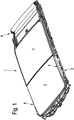
- a sunroof system 1 after the Fig. 1 to 8 has a movable roof part 2, which in a closed position according to Fig. 1 a roof opening closes, which is provided within a roof frame module 3.
- the roof frame module 3 is intended to be mounted in a cutout roof area of a passenger car in order to provide a passenger compartment of the passenger car with an openable sliding roof system 1.
- the roof frame module 3 is provided on opposite longitudinal sides, each with a drive side 5, which are part of a drive system, according to the movable roof part 2 from the closed position Fig. 1 to be converted into an obliquely upwardly exposed ventilation position and in a rearward in the vehicle longitudinal direction displaced opening position.
- the movable roof part 2 In the open position, the movable roof part 2 is positioned below a fixed roof section 4 of the roof frame module 3. On the rear side, the roof frame module 3 also has a shading device 6. The shading device 6 is provided because both the movable roof part 2 and the fixed roof section 4 are made of an at least partially transparent glass material.
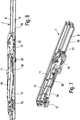
- Each of the two drive sides 5 is in accordance with Fig. 2 to 8 executed, using the Fig. 2 to 8 a - viewed in the normal direction of travel of the passenger car - left drive side 5 is shown.
- the opposite drive side 5 is functionally identical.
- Corresponding functional components of the right drive side 5 are mirror-symmetrical to a vertical vehicle center longitudinal plane, but otherwise arranged and designed identically to the functional components of the left drive side 5. Below only the - viewed in the normal direction - left drive side 5 will be described in more detail. The described applies in the same way for the right drive side. 5
- the central drive unit has an electric motor accommodated in a front region of the roof frame module 3 with an associated transmission which acts synchronously on two drive transmission means in the form of flexible pitch cables which are routed in the roof frame module 3 to the opposite drive sides 5.
- Each pitch cable is laid in the region of the corresponding longitudinal side of the movable roof part 2 and the roof frame module 3 in each case a guide rail assembly 7 and connected to a drive carriage 15 which is guided longitudinally movable in the guide rail assembly 7 in the vehicle longitudinal direction.
- the drive side 5 has a carrier profile 11, which is elongated and oriented upright and is firmly connected over almost an entire length of the movable roof part 2 with a left side region of the roof part 2. A displacement of the carrier profile 11 of each drive side 5 thus necessarily causes a corresponding displacement of the movable roof part 2.
- the carrier profile 11 is the front side (relative to an orientation in the vehicle longitudinal direction) pivotally connected to a balance lever 13. A corresponding pivot axis of the pivot joint extends in the vehicle transverse direction.
- the compensation lever 13 is pivotally mounted on a bearing carriage 12 by means of a further pivot point. The bearing of the balance lever 13 on the bearing carriage 12 is spaced downwardly and rearwardly to the pivot joint for the support section 11.
- the bearing carriage 12 is slidably mounted by means of corresponding sliding elements in the guide rail assembly 7 so as to be longitudinally displaceable.
- the guide rail arrangement 7 has two guide planes 8, 9 arranged one above the other, of which the guide plane 8 forms an upper guide plane and the guide plane 9 forms a lower guide plane.
- the bearing carriage 12 is guided with an outer sliding element in the lower guide level 9 and with internal sliding elements in the upper guide level 8.
- the drive carriage 15 has sliding elements, which are guided in the lower guide level 9, and other sliding elements, which are guided in the upper guide level 8.
- the outer slide elements in the region of the lower guide plane 9 and the inner slide elements in the region of the upper guide plane 8 are also positioned in the drive slide 15.
- the compensating lever 13 is guided in a sliding guide 16 of the drive carriage 15 slidably substantially linearly movable. As a result, a relative mobility between the balance lever 13 and the drive carriage 15 is given.
- the drive carriage 15 engages by means of a link guide 17 a control link 18 of the carrier profile 11, which serves for raising and lowering of the carrier profile 11 about the front pivot axis on the balance lever 13.
- the carrier profile 11 is therefore supported on the drive carriage 15 at a distance from its front pivot axis.
- a control lever 14 is articulated, which extends within the guide rail assembly 7 in the vehicle longitudinal direction to the rear.
- the control lever 14 is pivotally mounted on a bearing point arranged behind the hinge point for the balance lever 13 on the bearing carriage 12 about a pivot axis extending in the vehicle transverse direction.
- the control lever 14 serves, the bearing carriage 12 together with the balance lever 13 and the front end portion of the support section 11 against a displacement in the vehicle longitudinal direction, d. H. in the longitudinal direction of the guide rail arrangement 7, or to release the corresponding functional components for a displacement in the longitudinal direction.
- control lever 14 at a distance behind the bearing point on a locking cam 19, which dips into certain functional positions of the support section 11 and the control lever 14 in a locking recess 19 in a bottom 10 of the guide rail assembly 7.
- the control lever 14 is positively secured against displacement in the longitudinal direction of the guide rail assembly 7 positively.
- the bearing carriage 12 is blocked against displacement in the longitudinal direction of the guide rail assembly 7.
- the carrier profile 11 is articulated, and the carrier profile 11 is secured against displacement in the vehicle longitudinal direction to the rear.
- the rear end region of the control lever 14 also has a hook-like catching gate 23 which projects into a path of movement of a control contour 24 of the drive carriage 15.
- the Fangkulisse 23 is oriented obliquely so that the control contour 24 of the drive carriage 15 in an abutment against an oblique edge of the catch slide 23 inevitably pivoted the control lever 14 upwards, whereby the locking cam 19, which is fixedly arranged in the region of the underside of the control lever 14 is, from the locking recess 20 in the bottom 10 of the guide rail assembly 7 comes free.
- the control lever 14 has below the catching gate 23 also has a support roller 21 which is rotatably supported by a bearing pin in a bearing receptacle of the rear Stirnend Schemes of the control lever 14.
- the support roller 21 is rotatably mounted on the control lever 14 about an axis of rotation extending in the vehicle transverse direction and thus parallel to a pivot axis of the control lever 14.
- the support roller 21 protrudes downwards over a lower edge contour of the control lever 14 such that the support roller 21, when rolled along the floor 10 of the guide rail arrangement 7, supports the control lever 14 at a distance from the bottom 10 of the guide rail arrangement 7.
- the distance is selected so that when supporting the control lever 14 on the floor 10 of the guide rail assembly 7 by the support roller 21 of the locking cam 19 is positioned without contact at a small distance above the bottom 10 of the lower guide plane 9 of the guide rail 7. Therefore, when the support roller 21 unrolls on the floor 10 of the guide rail assembly 7, a footprint of the support roller 21 is the only support surface on which the control lever 14 is in contact with the floor 10 of the guide rail assembly 7.
- An underside of the latching cam 19 is positioned at a short distance above the bottom 10 and floats equally above the bottom 10.
- a receptacle 22 is provided in the bottom 10 of the guide rail assembly 7, in which the support roller 21 can dip down.
- the receptacle 22 is provided at a distance in the longitudinal direction of the guide rail assembly 7 behind the locking recess 20 in the bottom 10 of the guide rail assembly 7, which at least largely corresponds to the distance of the support roller 21 to the locking cam 19. While a receiving contour of the locking recess 20 is at least largely adapted form fit to an outer contour of the locking cam 19 of the control lever 14, the receptacle 22 is substantially larger than a cross-sectional area of the support roller 21.
- the receptacle 22 is designed so long and wide that the support roller 21 both in Transverse direction and in the longitudinal direction of the guide rail assembly 7 together with a corresponding holding portion of the rear Stirnend Schemes of the control lever 14 in the receptacle 22 can dive down.
- a corresponding dimensioning of the receptacle 22 is based on the Fig. 2 to 7 recognizable, wherein the size ratios between the support roller 21, the control lever 14 and the receptacle 22 are true to scale.
- the drive carriage 15 If the carrier profile is to be transferred from a closed position of the roof part in a ventilation position, the drive carriage 15 is moved forward in the guide rail assembly 7. As a result, the slide guide 17 presses on the control link 18, the support section 11 inevitably upwards, while the support profile is secured via the balance lever 13 and the bearing carriage 12 in the longitudinal direction of the guide rail assembly 7. The bearing carriage 12 is blocked by the control lever 14, which is locked by means of its latching cam 19 in the locking recess 20 in the longitudinal direction. If the drive carriage 15 reverses its direction of movement by the corresponding pitch cable of the drive system is moved in the opposite direction to the rear, moves the drive carriage 15 within the guide rail assembly 7 to the rear and pulls on the slide guide 17 and the control link 18, the support section 11 inevitably down.
Landscapes
- Engineering & Computer Science (AREA)
- Mechanical Engineering (AREA)
- Body Structure For Vehicles (AREA)
- Power-Operated Mechanisms For Wings (AREA)
- Air-Conditioning For Vehicles (AREA)
- Fittings On The Vehicle Exterior For Carrying Loads, And Devices For Holding Or Mounting Articles (AREA)
Applications Claiming Priority (1)
| Application Number | Priority Date | Filing Date | Title |
|---|---|---|---|
| DE102016203934.2A DE102016203934B4 (de) | 2016-03-10 | 2016-03-10 | Schiebedachsystem für ein Kraftfahrzeug |
Publications (1)
| Publication Number | Publication Date |
|---|---|
| EP3219528A1 true EP3219528A1 (fr) | 2017-09-20 |
Family
ID=58108496
Family Applications (1)
| Application Number | Title | Priority Date | Filing Date |
|---|---|---|---|
| EP17157263.9A Withdrawn EP3219528A1 (fr) | 2016-03-10 | 2017-02-21 | Systeme de toit coulissant pour un vehicule automobile |
Country Status (5)
| Country | Link |
|---|---|
| US (1) | US9975410B2 (fr) |
| EP (1) | EP3219528A1 (fr) |
| CN (1) | CN107176019B (fr) |
| DE (1) | DE102016203934B4 (fr) |
| MX (1) | MX2017002433A (fr) |
Cited By (1)
| Publication number | Priority date | Publication date | Assignee | Title |
|---|---|---|---|---|
| WO2020144080A1 (fr) * | 2019-01-11 | 2020-07-16 | Bos Gmbh & Co. Kg | Système d'entraînement conçu pour une pièce de toit mobile d'un module de toit d'un véhicule automobile |
Families Citing this family (4)
| Publication number | Priority date | Publication date | Assignee | Title |
|---|---|---|---|---|
| DE102018130017A1 (de) * | 2018-11-27 | 2020-05-28 | Roof Systems Germany Gmbh | Schiebedachsystem für ein Kraftfahrzeug |
| CN109367374B (zh) * | 2018-12-13 | 2024-05-28 | 江苏德福来汽车部件有限公司 | 一种外滑式天窗机械组 |
| DE112020000383A5 (de) * | 2019-01-11 | 2021-09-16 | Bos Gmbh & Co. Kg | Antriebssystem für ein bewegliches Dachteil eines Dachsystems eines Kraftfahrzeugs |
| CN111942122A (zh) * | 2020-07-23 | 2020-11-17 | 江苏德福来汽车部件有限公司 | 一种外滑车顶天窗机械组 |
Citations (4)
| Publication number | Priority date | Publication date | Assignee | Title |
|---|---|---|---|---|
| DE3910894A1 (de) * | 1988-04-05 | 1989-11-02 | Aisin Seiki | Bewegungsmechanismus fuer eine dachtafel eines sonnendachs |
| WO2008049409A1 (fr) * | 2006-10-25 | 2008-05-02 | Webasto Ag | Toit de véhicule comprenant un élément de toit mobile |
| DE102011085177A1 (de) | 2011-10-25 | 2013-04-25 | Bos Gmbh & Co. Kg | Antriebssystem für ein KFZ-Dachsystem |
| EP3009283A2 (fr) * | 2014-10-17 | 2016-04-20 | BOS GmbH & Co. KG | Systeme d'entrainement pour une partie de toit mobile d'un module de toit de vehicule automobile |
Family Cites Families (7)
| Publication number | Priority date | Publication date | Assignee | Title |
|---|---|---|---|---|
| US5154482A (en) * | 1990-03-31 | 1992-10-13 | Aisin Seiki Kabushiki Kaisha | Outer sliding-type sunroof |
| DE4320106C2 (de) | 1993-06-17 | 1997-08-14 | Hs Products Ag Systemtechnik U | Vorrichtung zur Steuerung der Bewegung eines Fahrzeugschiebedachdeckels |
| JPH0740746A (ja) * | 1993-07-29 | 1995-02-10 | Aisin Seiki Co Ltd | 車両用サンルーフ装置のチエツク機構 |
| DE102007061091A1 (de) * | 2007-12-19 | 2009-06-25 | Arvinmeritor Gmbh | Schiebedachsystem für ein Kraftfahrzeug |
| DE102008017489B3 (de) * | 2008-04-03 | 2009-09-10 | Webasto Ag | Deckelvorrichtung eines öffnungsfähigen Fahrzeugdaches mit einer Notbetätigung |
| JP5671914B2 (ja) * | 2010-09-29 | 2015-02-18 | アイシン精機株式会社 | 車両用ルーフ装置 |
| DE102013005217B4 (de) * | 2013-03-27 | 2019-03-14 | Webasto SE | Fahrzeug-Schiebedachvorrichtung mit zwei verstellbaren Deckeln |
-
2016
- 2016-03-10 DE DE102016203934.2A patent/DE102016203934B4/de active Active
-
2017
- 2017-02-21 EP EP17157263.9A patent/EP3219528A1/fr not_active Withdrawn
- 2017-02-23 MX MX2017002433A patent/MX2017002433A/es unknown
- 2017-03-01 US US15/446,267 patent/US9975410B2/en active Active
- 2017-03-10 CN CN201710140764.4A patent/CN107176019B/zh not_active Expired - Fee Related
Patent Citations (4)
| Publication number | Priority date | Publication date | Assignee | Title |
|---|---|---|---|---|
| DE3910894A1 (de) * | 1988-04-05 | 1989-11-02 | Aisin Seiki | Bewegungsmechanismus fuer eine dachtafel eines sonnendachs |
| WO2008049409A1 (fr) * | 2006-10-25 | 2008-05-02 | Webasto Ag | Toit de véhicule comprenant un élément de toit mobile |
| DE102011085177A1 (de) | 2011-10-25 | 2013-04-25 | Bos Gmbh & Co. Kg | Antriebssystem für ein KFZ-Dachsystem |
| EP3009283A2 (fr) * | 2014-10-17 | 2016-04-20 | BOS GmbH & Co. KG | Systeme d'entrainement pour une partie de toit mobile d'un module de toit de vehicule automobile |
Cited By (2)
| Publication number | Priority date | Publication date | Assignee | Title |
|---|---|---|---|---|
| WO2020144080A1 (fr) * | 2019-01-11 | 2020-07-16 | Bos Gmbh & Co. Kg | Système d'entraînement conçu pour une pièce de toit mobile d'un module de toit d'un véhicule automobile |
| US11623501B2 (en) | 2019-01-11 | 2023-04-11 | Bos Gmbh & Co. Kg | Drive system for a movable roof part of a roof module of a motor vehicle |
Also Published As
| Publication number | Publication date |
|---|---|
| CN107176019A (zh) | 2017-09-19 |
| DE102016203934B4 (de) | 2019-05-29 |
| MX2017002433A (es) | 2018-08-15 |
| CN107176019B (zh) | 2021-07-13 |
| DE102016203934A1 (de) | 2017-09-14 |
| US9975410B2 (en) | 2018-05-22 |
| US20170259651A1 (en) | 2017-09-14 |
Similar Documents
| Publication | Publication Date | Title |
|---|---|---|
| DE102017207892B4 (de) | Antriebssystem für ein bewegliches Dachteil eines Spoilerdachmoduls eines Kraftfahrzeugs | |
| EP2925548B1 (fr) | Système de toit pour véhicule automobile | |
| EP3009283B1 (fr) | Systeme d'entrainement pour une partie de toit mobile d'un module de toit de vehicule automobile | |
| DE102015201587A1 (de) | Antriebssystem für einen beweglichen Dachteil eines Dachmoduls eines Kraftfahrzeugs | |
| EP0317730A1 (fr) | Toit ouvrant relevable pour véhicules automobiles | |
| DE102016203934B4 (de) | Schiebedachsystem für ein Kraftfahrzeug | |
| EP3401144A1 (fr) | Système d'entraînement pour une partie de toit mobile d'un module de toit d'aileron d'un véhicule automobile | |
| EP2108536B1 (fr) | Toit de véhicule doté d'un capot réglable et d'un dispositif d'entraînement de capot | |
| DE10208185B4 (de) | Windabweiseranordnung für ein Fahrzeugdach | |
| WO2015024944A1 (fr) | Toit ouvrant de véhicule muni d'un panneau de couverture réglable | |
| DE10212241B4 (de) | Fahrzeug mit einem zu öffnenden Fahrzeugdach | |
| DE102013005217B4 (de) | Fahrzeug-Schiebedachvorrichtung mit zwei verstellbaren Deckeln | |
| DE102016201576A1 (de) | Schiebedachsystem für ein Kraftfahrzeug | |
| DE102016220991A1 (de) | Antriebssystem für ein bewegliches Dachteil eines Kraftfahrzeug-Dachmoduls | |
| EP3138711A2 (fr) | Systeme de toit de vehicule automobile | |
| DE102012008839A1 (de) | Verstellmechanik eines Karosseriebauteils | |
| DE102006052073A1 (de) | Cabriolet-Kraftfahrzeug | |
| DE102012008838A1 (de) | Öffnungsfähiges Fahrzeugdach mit einer Wasserauffangeinrichtung | |
| DE102017206309A1 (de) | Kraftfahrzeug mit einer Laderaumabdeckung | |
| DE102012008827A1 (de) | Rahmenanordnung eines öffnungsfähigen Fahrzeugdaches | |
| DE102017204489A1 (de) | Schiebedachsystem für ein Kraftfahrzeug | |
| DE102012008826A1 (de) | Deckel eines öffnungsfähigen Fahrzeugdaches | |
| EP3141411B1 (fr) | Systeme de toit coulissant pour un vehicule automobile | |
| DE102019003093A1 (de) | Fahrzeugdach mit einem Dachmodul | |
| DE10341527B4 (de) | Führung eines Fahrzeugteils mit einer Abdeckung |
Legal Events
| Date | Code | Title | Description |
|---|---|---|---|
| PUAI | Public reference made under article 153(3) epc to a published international application that has entered the european phase |
Free format text: ORIGINAL CODE: 0009012 |
|
| AK | Designated contracting states |
Kind code of ref document: A1 Designated state(s): AL AT BE BG CH CY CZ DE DK EE ES FI FR GB GR HR HU IE IS IT LI LT LU LV MC MK MT NL NO PL PT RO RS SE SI SK SM TR |
|
| AX | Request for extension of the european patent |
Extension state: BA ME |
|
| STAA | Information on the status of an ep patent application or granted ep patent |
Free format text: STATUS: THE APPLICATION IS DEEMED TO BE WITHDRAWN |
|
| 18D | Application deemed to be withdrawn |
Effective date: 20180321 |