EP3219599A1 - Load distribution apparatus of magnetic wheel - Google Patents
Load distribution apparatus of magnetic wheel Download PDFInfo
- Publication number
- EP3219599A1 EP3219599A1 EP15859480.4A EP15859480A EP3219599A1 EP 3219599 A1 EP3219599 A1 EP 3219599A1 EP 15859480 A EP15859480 A EP 15859480A EP 3219599 A1 EP3219599 A1 EP 3219599A1
- Authority
- EP
- European Patent Office
- Prior art keywords
- space portion
- distribution apparatus
- load distribution
- cylinder
- lower space
- Prior art date
- Legal status (The legal status is an assumption and is not a legal conclusion. Google has not performed a legal analysis and makes no representation as to the accuracy of the status listed.)
- Granted
Links
Images





Classifications
-
- B—PERFORMING OPERATIONS; TRANSPORTING
- B60—VEHICLES IN GENERAL
- B60G—VEHICLE SUSPENSION ARRANGEMENTS
- B60G21/00—Interconnection systems for two or more resiliently-suspended wheels, e.g. for stabilising a vehicle body with respect to acceleration, deceleration or centrifugal forces
- B60G21/02—Interconnection systems for two or more resiliently-suspended wheels, e.g. for stabilising a vehicle body with respect to acceleration, deceleration or centrifugal forces permanently interconnected
- B60G21/06—Interconnection systems for two or more resiliently-suspended wheels, e.g. for stabilising a vehicle body with respect to acceleration, deceleration or centrifugal forces permanently interconnected fluid
-
- B—PERFORMING OPERATIONS; TRANSPORTING
- B60—VEHICLES IN GENERAL
- B60G—VEHICLE SUSPENSION ARRANGEMENTS
- B60G21/00—Interconnection systems for two or more resiliently-suspended wheels, e.g. for stabilising a vehicle body with respect to acceleration, deceleration or centrifugal forces
- B60G21/02—Interconnection systems for two or more resiliently-suspended wheels, e.g. for stabilising a vehicle body with respect to acceleration, deceleration or centrifugal forces permanently interconnected
- B60G21/06—Interconnection systems for two or more resiliently-suspended wheels, e.g. for stabilising a vehicle body with respect to acceleration, deceleration or centrifugal forces permanently interconnected fluid
- B60G21/067—Interconnection systems for two or more resiliently-suspended wheels, e.g. for stabilising a vehicle body with respect to acceleration, deceleration or centrifugal forces permanently interconnected fluid between wheels on different axles on the same side of the vehicle, i.e. the left or the right side
-
- B—PERFORMING OPERATIONS; TRANSPORTING
- B08—CLEANING
- B08B—CLEANING IN GENERAL; PREVENTION OF FOULING IN GENERAL
- B08B1/00—Cleaning by methods involving the use of tools
- B08B1/30—Cleaning by methods involving the use of tools by movement of cleaning members over a surface
-
- B—PERFORMING OPERATIONS; TRANSPORTING
- B08—CLEANING
- B08B—CLEANING IN GENERAL; PREVENTION OF FOULING IN GENERAL
- B08B3/00—Cleaning by methods involving the use or presence of liquid or steam
- B08B3/02—Cleaning by the force of jets or sprays
- B08B3/022—Cleaning travelling work
-
- B—PERFORMING OPERATIONS; TRANSPORTING
- B25—HAND TOOLS; PORTABLE POWER-DRIVEN TOOLS; MANIPULATORS
- B25J—MANIPULATORS; CHAMBERS PROVIDED WITH MANIPULATION DEVICES
- B25J11/00—Manipulators not otherwise provided for
- B25J11/008—Manipulators for service tasks
- B25J11/0085—Cleaning
-
- B—PERFORMING OPERATIONS; TRANSPORTING
- B25—HAND TOOLS; PORTABLE POWER-DRIVEN TOOLS; MANIPULATORS
- B25J—MANIPULATORS; CHAMBERS PROVIDED WITH MANIPULATION DEVICES
- B25J5/00—Manipulators mounted on wheels or on carriages
-
- B—PERFORMING OPERATIONS; TRANSPORTING
- B25—HAND TOOLS; PORTABLE POWER-DRIVEN TOOLS; MANIPULATORS
- B25J—MANIPULATORS; CHAMBERS PROVIDED WITH MANIPULATION DEVICES
- B25J5/00—Manipulators mounted on wheels or on carriages
- B25J5/007—Manipulators mounted on wheels or on carriages mounted on wheels
-
- B—PERFORMING OPERATIONS; TRANSPORTING
- B60—VEHICLES IN GENERAL
- B60B—VEHICLE WHEELS; CASTORS; AXLES FOR WHEELS OR CASTORS; INCREASING WHEEL ADHESION
- B60B19/00—Wheels not otherwise provided for or having characteristics specified in one of the subgroups of this group
-
- B—PERFORMING OPERATIONS; TRANSPORTING
- B60—VEHICLES IN GENERAL
- B60B—VEHICLE WHEELS; CASTORS; AXLES FOR WHEELS OR CASTORS; INCREASING WHEEL ADHESION
- B60B19/00—Wheels not otherwise provided for or having characteristics specified in one of the subgroups of this group
- B60B19/006—Magnetic wheels
-
- B—PERFORMING OPERATIONS; TRANSPORTING
- B60—VEHICLES IN GENERAL
- B60G—VEHICLE SUSPENSION ARRANGEMENTS
- B60G15/00—Resilient suspensions characterised by arrangement, location or type of combined spring and vibration damper, e.g. telescopic type
- B60G15/08—Resilient suspensions characterised by arrangement, location or type of combined spring and vibration damper, e.g. telescopic type having fluid spring
- B60G15/12—Resilient suspensions characterised by arrangement, location or type of combined spring and vibration damper, e.g. telescopic type having fluid spring and fluid damper
-
- B—PERFORMING OPERATIONS; TRANSPORTING
- B60—VEHICLES IN GENERAL
- B60G—VEHICLE SUSPENSION ARRANGEMENTS
- B60G3/00—Resilient suspensions for a single wheel
- B60G3/01—Resilient suspensions for a single wheel the wheel being mounted for sliding movement, e.g. in or on a vertical guide
-
- B—PERFORMING OPERATIONS; TRANSPORTING
- B63—SHIPS OR OTHER WATERBORNE VESSELS; RELATED EQUIPMENT
- B63B—SHIPS OR OTHER WATERBORNE VESSELS; EQUIPMENT FOR SHIPPING
- B63B59/00—Hull protection specially adapted for vessels; Cleaning devices specially adapted for vessels
- B63B59/06—Cleaning devices for hulls
-
- B—PERFORMING OPERATIONS; TRANSPORTING
- B63—SHIPS OR OTHER WATERBORNE VESSELS; RELATED EQUIPMENT
- B63B—SHIPS OR OTHER WATERBORNE VESSELS; EQUIPMENT FOR SHIPPING
- B63B59/00—Hull protection specially adapted for vessels; Cleaning devices specially adapted for vessels
- B63B59/06—Cleaning devices for hulls
- B63B59/08—Cleaning devices for hulls of underwater surfaces while afloat
-
- B—PERFORMING OPERATIONS; TRANSPORTING
- B63—SHIPS OR OTHER WATERBORNE VESSELS; RELATED EQUIPMENT
- B63B—SHIPS OR OTHER WATERBORNE VESSELS; EQUIPMENT FOR SHIPPING
- B63B73/00—Building or assembling vessels or marine structures, e.g. hulls or offshore platforms
- B63B73/40—Building or assembling vessels or marine structures, e.g. hulls or offshore platforms characterised by joining methods
-
- F—MECHANICAL ENGINEERING; LIGHTING; HEATING; WEAPONS; BLASTING
- F16—ENGINEERING ELEMENTS AND UNITS; GENERAL MEASURES FOR PRODUCING AND MAINTAINING EFFECTIVE FUNCTIONING OF MACHINES OR INSTALLATIONS; THERMAL INSULATION IN GENERAL
- F16F—SPRINGS; SHOCK-ABSORBERS; MEANS FOR DAMPING VIBRATION
- F16F9/00—Springs, vibration-dampers, shock-absorbers, or similarly-constructed movement-dampers using a fluid or the equivalent as damping medium
- F16F9/32—Details
- F16F9/3207—Constructional features
- F16F9/3214—Constructional features of pistons
-
- F—MECHANICAL ENGINEERING; LIGHTING; HEATING; WEAPONS; BLASTING
- F16—ENGINEERING ELEMENTS AND UNITS; GENERAL MEASURES FOR PRODUCING AND MAINTAINING EFFECTIVE FUNCTIONING OF MACHINES OR INSTALLATIONS; THERMAL INSULATION IN GENERAL
- F16F—SPRINGS; SHOCK-ABSORBERS; MEANS FOR DAMPING VIBRATION
- F16F9/00—Springs, vibration-dampers, shock-absorbers, or similarly-constructed movement-dampers using a fluid or the equivalent as damping medium
- F16F9/32—Details
- F16F9/3207—Constructional features
- F16F9/3221—Constructional features of piston rods
-
- F—MECHANICAL ENGINEERING; LIGHTING; HEATING; WEAPONS; BLASTING
- F16—ENGINEERING ELEMENTS AND UNITS; GENERAL MEASURES FOR PRODUCING AND MAINTAINING EFFECTIVE FUNCTIONING OF MACHINES OR INSTALLATIONS; THERMAL INSULATION IN GENERAL
- F16F—SPRINGS; SHOCK-ABSORBERS; MEANS FOR DAMPING VIBRATION
- F16F9/00—Springs, vibration-dampers, shock-absorbers, or similarly-constructed movement-dampers using a fluid or the equivalent as damping medium
- F16F9/32—Details
- F16F9/58—Stroke limiting stops, e.g. arranged on the piston rod outside the cylinder
- F16F9/585—Stroke limiting stops, e.g. arranged on the piston rod outside the cylinder within the cylinder, in contact with working fluid
-
- B—PERFORMING OPERATIONS; TRANSPORTING
- B60—VEHICLES IN GENERAL
- B60G—VEHICLE SUSPENSION ARRANGEMENTS
- B60G2300/00—Indexing codes relating to the type of vehicle
-
- B—PERFORMING OPERATIONS; TRANSPORTING
- B60—VEHICLES IN GENERAL
- B60G—VEHICLE SUSPENSION ARRANGEMENTS
- B60G2400/00—Indexing codes relating to detected, measured or calculated conditions or factors
- B60G2400/60—Load
- B60G2400/61—Load distribution
-
- B—PERFORMING OPERATIONS; TRANSPORTING
- B63—SHIPS OR OTHER WATERBORNE VESSELS; RELATED EQUIPMENT
- B63B—SHIPS OR OTHER WATERBORNE VESSELS; EQUIPMENT FOR SHIPPING
- B63B59/00—Hull protection specially adapted for vessels; Cleaning devices specially adapted for vessels
- B63B59/06—Cleaning devices for hulls
- B63B2059/065—Cleaning devices for hulls mounted on land-borne vehicles, e.g. travelling on the bottom of a dry-dock
Definitions
- the present invention relates to a load distribution apparatus of magnetic wheel and more particularly, to a load distribution apparatus of magnetic wheel, which is capable of evenly distributing a load applied to a plurality of magnetic wheels, thereby allowing the maximal utilization of individual adsorptive forces of the magnetic wheels.
- aquatic creatures living under water such as barnacles, sea squirts, serpula, mytilus galloprovincialis, freshwater shellfish, lagoon bugyul body, visible bluish, greener and so on, adhere to and live in a surface of the body of a ship, which does various damage to the ship.
- aquatic creatures adhered to the ship body may increase frictional resistance to seawater, thereby decreasing a sailing speed of the ship and increasing fuel consumption, which is at an economic disadvantage.
- a diver may clean the bottom of the ship under water, without moving the ship.
- it takes a long time to clean a wide range of ship body and the level of difficulty in the cleaning work increases due to poor visibility.
- KR Patent Registration No. 10-0811540 is a propulsive apparatus which moves along the wall of a ship body and cleans the wall using a brush fixed at the underwater robot.
- Some cleaning apparatuses using magnetic wheels have no consideration of uniformity of an attachment target surface including the ship bottom.
- the corresponding magnetic wheel may be detached from the attachment target surface and, accordingly, the overall force with which a cleaning apparatus is attached to the attachment target surface is weakened.
- attachment target surfaces of diagonally arranged magnetic wheels are lower than other attachment target surfaces, the diagonally arranged magnetic wheels are simultaneously separated from the attachment target surfaces. Therefore, since a load is weighted on magnetic wheels diagonally arranged in a different direction or three of four magnetic wheels contact the attachment target surfaces simultaneously and are obliquely attached to the attachment target surfaces, a magnetic force of the magnetic wheels cannot be properly delivered.
- providing springs in individual magnetic wheels may be considered.
- tension springs when the forefront magnetic wheel of a plurality of magnetic wheels is applied with a force and is attracted, there differs in forces applied to magnetic wheels arranged in the rear side depending on an elongation percentage of the tension springs. That is, the magnetic wheel located in the forefront shares the largest force and the magnetic wheel located in the rearmost shares the smallest. This is inefficient because the respective magnetic wheels do not evenly share an adsorptive force against an external force.
- Patent Document 1 KR Patent Registration No. 10-0811540 (owned by Daewoo Shipbuilding Marine Engineering Co. Ltd., and issued at 07/03/2008)
- a load distribution apparatus of magnetic wheel comprising: a plurality of cylinder parts including one sides respectively connected to a plurality of magnetic wheels and an upper space portion and a lower space portion whose interiors do not communicate to each other; and a passage part which serves as a moving path of fluid and interconnects the plurality of cylinder parts, wherein the passage part is configured to evenly distribute a load applied to the magnetic wheels by moving fluids in the upper space portion and the lower space portion in such a manner that the fluids are not mixed.
- each of the plurality of cylinder parts includes a cylinder body partitioned into the upper space portion and the lower space portion by a piston elevatably provided in the cylinder body; and a piston rod including one side connected to the piston and the other side connected to the magnetic wheel.
- a stopper to limit the descent height of the cylinder body is provided in the cylinder body or the piston rod.
- the stopper is provided in the cylinder body or the piston rod located in the forefront and in the cylinder body or the piston rod located in the rearmost.
- the cylinder bodies have the same inner diameter.
- the passage part includes a first passage interconnecting the upper space portions of the cylinder parts to communicate to each other; and a second passage interconnecting the lower space portions of the cylinder parts to communicate to each other.
- the load distribution apparatus is used for cleaning of the bottom of a ship.
- a load applied to the respective magnetic wheels can be evenly distributed by the plurality of cylinder parts and the passage part interconnecting the plurality of cylinder parts, it is possible to provide the maximal utilization of individual adsorptive forces of the magnetic wheels.
- FIG. 1 is a schematic view showing a load distribution apparatus of magnetic wheel according to one embodiment of the present invention.
- FIG. 2 is an enlarged view of a main part shown in FIG. 1 .
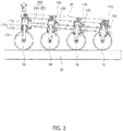
- FIG. 3 is a view for explaining a problem which may be caused when no stopper is provided in a piston rod shown in FIG. 1 .
- a load distribution apparatus 1 for magnetic wheels includes a plurality of cylinder parts 100 including one sides respectively connected to a plurality of magnetic wheels and an upper space portion 112 and a lower space portion 113 whose interiors do not communicate to each other, and a passage part 200 which serves as a moving path of fluid and interconnects the plurality of cylinder parts 100.
- the cylinder parts 100 may be provided to correspond to the magnetic wheels 10 and play a role to evenly distribute a load applied to the magnetic wheels 10 when a fluid accommodated in one cylinder part 100 is moved to another cylinder part 100 via the passage part 200.
- each of the cylinder parts 100 includes a cylinder body 110 partitioned into an upper space portion 112 and a lower space portion 113 by a piston 111 elevatably provided therein, and a piston rod 120 including an upper side connected to the piston 111 and a lower side connected to a magnetic wheel 10.
- an upper end of the cylinder body 110 of the cylinder part 100 can be removably coupled to a frame of a cleaning apparatus.
- the cylinder body 110 is partitioned into the upper space portion 112 and the lower space portion 113 by the piston 111 provided in the central portion and a fluid filled in the upper space portion 112 and a fluid filled in the lower space portion 113 are short-circuited to each other by the piston 111.
- this embodiment includes two closed fluid circuits, i.e., one being an upper space portion closed circuit of the fluid flowing in the upper space portion 112 and the other being a lower space portion closed circuit of the fluid flowing in the lower space portion 113.
- the cylinder bodies 110 may have the same inner diameter.
- the left cylinder body 110 and the right cylinder body 110 shown in FIG. 2 may the same inner diameter of 30mm.
- the diameter of the left and right piston rods 120 may be 20mm.
- the area of the piston 111 in contact with the upper space portion 112 is 7.0cm 2 and the area of the piston 111 in contact with the lower space portion 113 is 3.9cm 2 . That is, in this embodiment, the area of the piston 111 in contact with the upper space portion 112 may be different from the area of the piston 111 in contact with the lower space portion 113. If the left piston 111 is ascended by 1cm, the fluid accommodated in the left upper space portion 112 is pushed by 7.0cm 3 into the right upper space portion 112.
- the fluid in the left upper space portion 112 is moved by 7.0cm 3 into the right upper space portion 112 via a first passage 210 and descends the piston 111 in the right cylinder body 110. Since the pistons 111 in contact with the left and right upper space portions 112 have the same area, the descent distance of the piston 111 in the right cylinder body 110 is 1cm.
- the right lower space portion 113 is descended by 1cm and the fluid in the right lower space portion 113 is moved by 3.9cm 3 into the left lower space portion 113 via a second passage 220. Since the pistons 111 in contact with the left and right lower space portions 113 have the same area, the ascent distance of the piston 111 in the left lower space portion 113 is 1cm.
- the lower side of the piston rod 120 of the cylinder part 100 can be removably fitted into a shaft of the magnetic wheel 10 and the upper side thereof can be removably fitted into or welded to the piston 111.
- a stopper 121 is provided in each of the forefront and rearmost piston rods 120, as shown in FIG. 1 .
- the stopper 121 serves to maintain the lower space portion 113 of the cylinder body 110 at a specified pressure, distribute an external force F, and prevent the apparatus from being excessively tilted.
- the external force F is concentrated on the leftmost magnetic wheel 10 through the piston in direct contact with the lower space portion 113 and, accordingly, cannot be evenly distributed over the entire magnetic wheels 10.
- the apparatus may be excessively tilted.
- the passage part 200 serves to interconnect the cylinders and flow the fluid in the cylinders while forming a closed circuit.
- the passage part 200 includes a first passage 210 for interconnecting the upper space portions 112 of the cylinder bodies 110 to form a closed circuit and a second passage 220 for interconnecting the lower space portions 113 of the cylinder bodies 110 to form a closed circuit.
- the fluid (e.g., oil or compressed gas) stored in the upper space portion 112 is moved into only other upper space portions 112 via the first passage 210 but is not moved into the lower space portions 113. This is equally applied to the lower space portions 113.
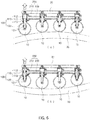
- FIGs. 4 to 6 are view for explaining the operation of the apparatus according to this embodiment.
- the reason for application of the force F is as follows.
- the apparatus using the magnetic wheels 10 is climbed on or attached to a wall of a ferromagnetic body as an attachment object 20, with heavy components and power/communication cables equipped in the apparatus. All components equipped in the apparatus are affected by an external force such as gravity which tries to separate the apparatus from the attachment object 20. Therefore, the description is given with the presumption that the force F is applied to the apparatus.
- FIG. 5 shows a situation where the apparatus of this embodiment encounters and crosses a protruding bump existing on the attachment object 20, with a force applied in the direction F.
- the diameter of each of the magnetic wheels 10 is 200mm and the height of the protruding bump is 20mm, and a stroke of each of the pistons 111 is 100mm.
- the stroke of the piston 111 may be increased to cross a larger protruding bump.
- FIG. 6 shows a situation where the apparatus moves over a large curved surface with a force applied in the direction F.
- the height of the stopper 121 may be changed according to situations.
- the diameter of each of the magnetic wheels 10 is 200mm
- the stroke of each of the pistons 111 is 100mm
- the radius of the attachment object 20 is 2.5m.
- FIG. 7 is a state diagram of use of the apparatus according to this embodiment.
- This embodiment can be applied to a wide range of fields including welding, machining and so on, which are performed on ferromagnetic bodies, in addition to the ship cleaning apparatus.
- the magnetic wheels 10 may be in the form of a wheel including a permanent magnet or an electromagnet.
Landscapes
- Engineering & Computer Science (AREA)
- Mechanical Engineering (AREA)
- General Engineering & Computer Science (AREA)
- Chemical & Material Sciences (AREA)
- Combustion & Propulsion (AREA)
- Ocean & Marine Engineering (AREA)
- Robotics (AREA)
- Architecture (AREA)
- Structural Engineering (AREA)
- Cleaning In General (AREA)
- Manipulator (AREA)
Abstract
Description
- The present invention relates to a load distribution apparatus of magnetic wheel and more particularly, to a load distribution apparatus of magnetic wheel, which is capable of evenly distributing a load applied to a plurality of magnetic wheels, thereby allowing the maximal utilization of individual adsorptive forces of the magnetic wheels.
- In general, aquatic creatures living under water, such as barnacles, sea squirts, serpula, mytilus galloprovincialis, freshwater shellfish, lagoon bugyul body, visible bluish, greener and so on, adhere to and live in a surface of the body of a ship, which does various damage to the ship.
- For example, aquatic creatures adhered to the ship body may increase frictional resistance to seawater, thereby decreasing a sailing speed of the ship and increasing fuel consumption, which is at an economic disadvantage.
- Conventionally, a cleaning work by a worker of moving a ship to be cleaned to a land dock and stripping off attachments of the wall of the ship by jetting water with a high pressure hose has been generally used. Since this method requires a preparation procedure to move the ship to the dock, there is a disadvantage that long cleaning time is taken and many workers are mobilized.
- A diver may clean the bottom of the ship under water, without moving the ship. However, even for a diver skilled at underwater work environments, it takes a long time to clean a wide range of ship body and the level of difficulty in the cleaning work increases due to poor visibility.
- In order to avoid the problem that cleaning the bottom of the ship by a worker is difficult to remove attachments efficiently and requires many workers, there has been proposed a method of applying paints mixed with toxic material in order to prevent marine creatures from adhering and parasitizing in the surface of a ship.
- However, the proposed method causes other problems of seawater pollution and detrimental effects on other marine creatures to destroy the aquatic ecosystems and is therefore forbidden by international organizations. In addition, when the toxicity decreases after lapse of certain time, paints should be again applied after cleaning.
- In order to overcome such a problem, there has been proposed a technique that a cleaning robot removes deposits while moving along the wall of a ship under water.
- "An underwater robot for cleaning and inspection of the bottom of a ship" disclosed in KR Patent Registration No.
10-0811540 - However, this method causes upsizing of cleaning equipment due to a propeller, which results in difficulty in efficient cleaning of the ship bottom having a large curvature, and requires many sensors used to stably move the robot along the wall of the ship body, which results in high costs.
- In order to clean the bottom of a ship, it is important to closely attach a cleaning apparatus to the ship bottom. To this end, there has been proposed a method of using a magnetic wheel.
- Some cleaning apparatuses using magnetic wheels have no consideration of uniformity of an attachment target surface including the ship bottom.
- In this case, if the attachment target surface to which one of the magnetic wheels is attached is lower than the ground, the corresponding magnetic wheel may be detached from the attachment target surface and, accordingly, the overall force with which a cleaning apparatus is attached to the attachment target surface is weakened.
- If attachment target surfaces of diagonally arranged magnetic wheels are lower than other attachment target surfaces, the diagonally arranged magnetic wheels are simultaneously separated from the attachment target surfaces. Therefore, since a load is weighted on magnetic wheels diagonally arranged in a different direction or three of four magnetic wheels contact the attachment target surfaces simultaneously and are obliquely attached to the attachment target surfaces, a magnetic force of the magnetic wheels cannot be properly delivered.
- In actuality, since the bottoms of most ferromagnetic bodies as attachment target surfaces are not flat, there is a disadvantage in that a design should be made in preparation for non-attachment of magnetic wheels to attachment target surfaces. In addition, more than four magnetic wheels are difficult to be mounted due to characteristics of the magnetic wheels that an adsorptive force is rapidly decreased if the magnetic wheels are separated from the attachment target surfaces.
- On the other hand, when magnetic wheels are attached to floors, walls, ceilings and so on formed of a ferromagnetic body, an external force exerts to separate the magnetic wheels rather than to press the magnetic wheels.
- Even if the volume of a magnet is increased twice, a magnetic force is increased less than twice. Therefore, the size of the magnet cannot be blindly increased. Therefore, in order to increase the adsorptive force of the magnetic wheels, it is more effective to use a number of magnetic wheels.
- In this case, providing springs in individual magnetic wheels may be considered. For example, in a case of using tension springs, when the forefront magnetic wheel of a plurality of magnetic wheels is applied with a force and is attracted, there differs in forces applied to magnetic wheels arranged in the rear side depending on an elongation percentage of the tension springs. That is, the magnetic wheel located in the forefront shares the largest force and the magnetic wheel located in the rearmost shares the smallest. This is inefficient because the respective magnetic wheels do not evenly share an adsorptive force against an external force.
- The above description is only provided as a background to assist in understandings of the present invention but is not intended to elucidate the technique known in the art to which the present invention belongs.
- (Patent Document 1) KR Patent Registration No.
10-0811540 - Accordingly, it is an object of the present invention to provide a load distribution apparatus of magnetic wheel, which is capable of evenly distributing a load applied to a plurality of magnetic wheels, thereby allowing the maximal utilization of individual adsorptive forces of the magnetic wheels.
- According to an aspect of the present invention, there is provided a load distribution apparatus of magnetic wheel, comprising: a plurality of cylinder parts including one sides respectively connected to a plurality of magnetic wheels and an upper space portion and a lower space portion whose interiors do not communicate to each other; and a passage part which serves as a moving path of fluid and interconnects the plurality of cylinder parts, wherein the passage part is configured to evenly distribute a load applied to the magnetic wheels by moving fluids in the upper space portion and the lower space portion in such a manner that the fluids are not mixed.
- Preferably, each of the plurality of cylinder parts includes a cylinder body partitioned into the upper space portion and the lower space portion by a piston elevatably provided in the cylinder body; and a piston rod including one side connected to the piston and the other side connected to the magnetic wheel.
- Preferably, a stopper to limit the descent height of the cylinder body is provided in the cylinder body or the piston rod.
- Preferably, the stopper is provided in the cylinder body or the piston rod located in the forefront and in the cylinder body or the piston rod located in the rearmost.
- Preferably, the cylinder bodies have the same inner diameter.
- Preferably, the passage part includes a first passage interconnecting the upper space portions of the cylinder parts to communicate to each other; and a second passage interconnecting the lower space portions of the cylinder parts to communicate to each other.
- Preferably, the load distribution apparatus is used for cleaning of the bottom of a ship.
- According to the embodiments of the present inventions, since a load applied to the respective magnetic wheels can be evenly distributed by the plurality of cylinder parts and the passage part interconnecting the plurality of cylinder parts, it is possible to provide the maximal utilization of individual adsorptive forces of the magnetic wheels.
-
-
FIG. 1 is a schematic view showing a load distribution apparatus of magnetic wheel according to one embodiment of the present invention. -
FIG. 2 is an enlarged view of a main part shown inFIG. 1 . -
FIG. 3 is a view for explaining a problem which may be caused when no stopper is provided in a piston rod shown inFIG. 1 . -
FIGs. 4 to 6 are view for explaining the operation of the apparatus according to this embodiment. -
FIG. 7 is a state diagram of use of the apparatus according to this embodiment. - In order to fully understand the present invention, advantages of operation of the present invention, and purposes achieved by embodiments of the present invention, the accompanying drawings illustrating preferred embodiments of the present invention and contents described in the accompanying drawings should be referenced.
- Hereinafter, preferred embodiments of the present invention will be described with reference to the accompanying drawings. Throughout the drawings, the same elements are denoted by the same reference numerals.
-
FIG. 1 is a schematic view showing a load distribution apparatus of magnetic wheel according to one embodiment of the present invention.FIG. 2 is an enlarged view of a main part shown inFIG. 1 .FIG. 3 is a view for explaining a problem which may be caused when no stopper is provided in a piston rod shown inFIG. 1 . - As shown in these figures, a
load distribution apparatus 1 for magnetic wheels according to this embodiment includes a plurality ofcylinder parts 100 including one sides respectively connected to a plurality of magnetic wheels and anupper space portion 112 and alower space portion 113 whose interiors do not communicate to each other, and apassage part 200 which serves as a moving path of fluid and interconnects the plurality ofcylinder parts 100. - As shown in
FIG. 1 , thecylinder parts 100 may be provided to correspond to themagnetic wheels 10 and play a role to evenly distribute a load applied to themagnetic wheels 10 when a fluid accommodated in onecylinder part 100 is moved to anothercylinder part 100 via thepassage part 200. - In this embodiment, as shown in
FIGs. 1 and2 , each of thecylinder parts 100 includes acylinder body 110 partitioned into anupper space portion 112 and alower space portion 113 by apiston 111 elevatably provided therein, and apiston rod 120 including an upper side connected to thepiston 111 and a lower side connected to amagnetic wheel 10. - As shown in
FIG. 1 , an upper end of thecylinder body 110 of thecylinder part 100 can be removably coupled to a frame of a cleaning apparatus. - In addition, as shown in
FIGs. 1 and2 , thecylinder body 110 is partitioned into theupper space portion 112 and thelower space portion 113 by thepiston 111 provided in the central portion and a fluid filled in theupper space portion 112 and a fluid filled in thelower space portion 113 are short-circuited to each other by thepiston 111. - Accordingly, the fluid filled in the
upper space portion 112 is moved to only theupper space portion 112 according to motion of thepiston 111 and the fluid filled in thelower space portion 113 is moved to only thelower space portion 113. As a result, this embodiment includes two closed fluid circuits, i.e., one being an upper space portion closed circuit of the fluid flowing in theupper space portion 112 and the other being a lower space portion closed circuit of the fluid flowing in thelower space portion 113. - In this embodiment, the
cylinder bodies 110 may have the same inner diameter. For example, theleft cylinder body 110 and theright cylinder body 110 shown inFIG. 2 may the same inner diameter of 30mm. - The diameter of the left and
right piston rods 120 may be 20mm. - Therefore, the area of the
piston 111 in contact with theupper space portion 112 is 7.0cm2 and the area of thepiston 111 in contact with thelower space portion 113 is 3.9cm2. That is, in this embodiment, the area of thepiston 111 in contact with theupper space portion 112 may be different from the area of thepiston 111 in contact with thelower space portion 113. If theleft piston 111 is ascended by 1cm, the fluid accommodated in the leftupper space portion 112 is pushed by 7.0cm3 into the rightupper space portion 112. - The fluid in the left
upper space portion 112 is moved by 7.0cm3 into the rightupper space portion 112 via afirst passage 210 and descends thepiston 111 in theright cylinder body 110. Since thepistons 111 in contact with the left and rightupper space portions 112 have the same area, the descent distance of thepiston 111 in theright cylinder body 110 is 1cm. - As a result, the right
lower space portion 113 is descended by 1cm and the fluid in the rightlower space portion 113 is moved by 3.9cm3 into the leftlower space portion 113 via asecond passage 220. Since thepistons 111 in contact with the left and rightlower space portions 113 have the same area, the ascent distance of thepiston 111 in the leftlower space portion 113 is 1cm. - The lower side of the
piston rod 120 of thecylinder part 100 can be removably fitted into a shaft of themagnetic wheel 10 and the upper side thereof can be removably fitted into or welded to thepiston 111. - In this embodiment, a
stopper 121 is provided in each of the forefront andrearmost piston rods 120, as shown inFIG. 1 . Thestopper 121 serves to maintain thelower space portion 113 of thecylinder body 110 at a specified pressure, distribute an external force F, and prevent the apparatus from being excessively tilted. - More specifically, as shown in
FIG. 3 , when theforefront piston 111 is in direct contact with thelower space portion 113 of thecylinder body 110, no pressure is generated in thelower space portion 113 and, accordingly, no pressure can be delivered toother cylinder bodies 110. - In addition, the external force F is concentrated on the leftmost
magnetic wheel 10 through the piston in direct contact with thelower space portion 113 and, accordingly, cannot be evenly distributed over the entiremagnetic wheels 10. - In this case, furthermore, as shown in
FIG. 3 , the apparatus may be excessively tilted. - The
passage part 200 serves to interconnect the cylinders and flow the fluid in the cylinders while forming a closed circuit. - In this embodiment, as shown in
FIG. 1 , thepassage part 200 includes afirst passage 210 for interconnecting theupper space portions 112 of thecylinder bodies 110 to form a closed circuit and asecond passage 220 for interconnecting thelower space portions 113 of thecylinder bodies 110 to form a closed circuit. - Accordingly, in this embodiment, the fluid (e.g., oil or compressed gas) stored in the
upper space portion 112 is moved into only otherupper space portions 112 via thefirst passage 210 but is not moved into thelower space portions 113. This is equally applied to thelower space portions 113. -
FIGs. 4 to 6 are view for explaining the operation of the apparatus according to this embodiment. - Hereinafter, the operation of the apparatus according to this embodiment will be described in brief with reference to
FIGs. 4 to 6 . - First, as shown in
FIG. 4 , when the force F is exerted at a position A of themagnetic wheel 10, thepiston 111 at the position A tries to move to thelower space portion 113 of thecylinder body 110 and, accordingly, a pressure is produced in the correspondinglower space portion 113. - The pressure produced in the
lower space portion 113 at the position A is equally applied to thelower space portions 113 at positions B, C and D according to the Pascal's principle. At this time, a force applied to eachmagnetic wheel 10 is obtained according to the formula 'Force = Pressure x Area.' Since thepistons 111 have the same area and pressure, the force applied to the respectivemagnetic wheels 10 is evenly distributed. - In the above example, the reason for application of the force F is as follows. In most cases, the apparatus using the
magnetic wheels 10 is climbed on or attached to a wall of a ferromagnetic body as anattachment object 20, with heavy components and power/communication cables equipped in the apparatus. All components equipped in the apparatus are affected by an external force such as gravity which tries to separate the apparatus from theattachment object 20. Therefore, the description is given with the presumption that the force F is applied to the apparatus. - When the pulling force lasts, as shown in
FIG. 4A , a force to push out the internal fluid of thecylinder body 110 exerts on thelower space portion 113 at the position A and a force to suck in the internal fluid of thecylinder body 110 exerts on theupper space portion 112 at the position A. - Since the total sum of volumes of internal fluids of the
respective cylinder bodies 110 is unchanged, the sum of fluids of theupper space portions 112 and the sum of fluids of thelower space portions 113 at the positions A, B, C and D are unchanged. - Accordingly, as shown in
FIG. 4B , the respective fluids in thecylinder bodies 110 are flown until thecylinder body 110 at the position D contacts thestopper 121. -
FIG. 5 shows a situation where the apparatus of this embodiment encounters and crosses a protruding bump existing on theattachment object 20, with a force applied in the direction F. - In the example shown in
FIG. 5 , the diameter of each of themagnetic wheels 10 is 200mm and the height of the protruding bump is 20mm, and a stroke of each of thepistons 111 is 100mm. - In this embodiment, the stroke of the
piston 111 may be increased to cross a larger protruding bump. -
FIG. 6 shows a situation where the apparatus moves over a large curved surface with a force applied in the direction F. - As indicated by the position D in
FIG. 6 , the height of thestopper 121 may be changed according to situations. - In the example shown in
FIG. 6 , the diameter of each of themagnetic wheels 10 is 200mm, the stroke of each of thepistons 111 is 100mm, and the radius of theattachment object 20 is 2.5m. -
FIG. 7 is a state diagram of use of the apparatus according to this embodiment. - In this embodiment, as shown in
FIG. 7 , when a plurality ofmagnetic wheels 10 are provide in the left and right side of aframe 30 of the apparatus, individual adsorptive forces of themagnetic wheels 10 can be maximized by evenly distributing a load applied to the respectivemagnetic wheels 10. - This embodiment can be applied to a wide range of fields including welding, machining and so on, which are performed on ferromagnetic bodies, in addition to the ship cleaning apparatus.
- In this embodiment, the
magnetic wheels 10 may be in the form of a wheel including a permanent magnet or an electromagnet. - As described above, according to this embodiment, since a load applied to the respective magnetic wheels can be evenly distributed by the plurality of cylinder parts and the passage part interconnecting the plurality of cylinder parts, it is possible to provide the maximal utilization of individual adsorptive forces of the magnetic wheels.
- While the present invention has been particularly shown and described with reference to exemplary embodiments thereof, it will be understood by those skilled in the art that various changes in form and details may be made therein without departing from the spirit and scope of the present invention. The exemplary embodiments are provided for the purpose of illustrating the invention, not in a limitative sense. Thus, it is intended that the present invention covers the modifications and variations of this invention provided they come within the scope of the appended claims and their equivalents.
Claims (7)
- A load distribution apparatus of magnetic wheel, comprising:a plurality of cylinder parts including one sides respectively connected to a plurality of magnetic wheels and an upper space portion and a lower space portion whose interiors do not communicate to each other; anda passage part which serves as a moving path of fluid and interconnects the plurality of cylinder parts,wherein the passage part is configured to evenly distribute a load applied to the magnetic wheels by moving fluids in the upper space portion and the lower space portion in such a manner that the fluids are not mixed.
- The load distribution apparatus according to claim 1, wherein each of the plurality of cylinder parts includes:a cylinder body partitioned into the upper space portion and the lower space portion by a piston elevatably provided in the cylinder body; anda piston rod including one side connected to the piston and the other side connected to the magnetic wheel.
- The load distribution apparatus according to claim 2, wherein a stopper to limit the descent height of the cylinder body is provided in the cylinder body or the piston rod.
- The load distribution apparatus according to claim 3, wherein the stopper is provided in the cylinder body or the piston rod located in the forefront and in the cylinder body or the piston rod located in the rearmost.
- The load distribution apparatus according to claim 2, wherein the cylinder bodies have the same inner diameter.
- The load distribution apparatus according to claim 1, wherein the passage part includes:a first passage interconnecting the upper space portions of the cylinder parts to communicate to each other; anda second passage interconnecting the lower space portions of the cylinder parts to communicate to each other.
- The load distribution apparatus according to claim 1, wherein the load distribution apparatus is used for cleaning of the bottom of a ship.
Applications Claiming Priority (2)
| Application Number | Priority Date | Filing Date | Title |
|---|---|---|---|
| KR1020140155253A KR101548604B1 (en) | 2014-11-10 | 2014-11-10 | Load separating apparatus for magnetic wheel |
| PCT/KR2015/011527 WO2016076555A1 (en) | 2014-11-10 | 2015-10-29 | Load distribution apparatus of magnetic wheel |
Publications (3)
| Publication Number | Publication Date |
|---|---|
| EP3219599A1 true EP3219599A1 (en) | 2017-09-20 |
| EP3219599A4 EP3219599A4 (en) | 2017-11-15 |
| EP3219599B1 EP3219599B1 (en) | 2019-08-21 |
Family
ID=54246752
Family Applications (1)
| Application Number | Title | Priority Date | Filing Date |
|---|---|---|---|
| EP15859480.4A Active EP3219599B1 (en) | 2014-11-10 | 2015-10-29 | Load distribution apparatus of magnetic wheel |
Country Status (8)
| Country | Link |
|---|---|
| US (1) | US10308093B2 (en) |
| EP (1) | EP3219599B1 (en) |
| JP (1) | JP6408165B2 (en) |
| KR (1) | KR101548604B1 (en) |
| CN (1) | CN107073705B (en) |
| ES (1) | ES2751651T3 (en) |
| TW (1) | TWI620685B (en) |
| WO (1) | WO2016076555A1 (en) |
Cited By (1)
| Publication number | Priority date | Publication date | Assignee | Title |
|---|---|---|---|---|
| CN111992387A (en) * | 2020-07-09 | 2020-11-27 | 江苏科技大学 | Marine wall-climbing robot spraying device for curved surface spraying operation |
Families Citing this family (8)
| Publication number | Priority date | Publication date | Assignee | Title |
|---|---|---|---|---|
| CN105737945B (en) * | 2016-03-01 | 2019-07-05 | 国网河南省电力公司南阳供电公司 | Power station barrage ultrasonic water level monitors radio speech prompting device and monitoring method |
| CN106428278B (en) * | 2016-10-25 | 2018-09-04 | 大连理工大学 | Motion control device for magnetic vehicle on structural surface of steel hull and using method thereof |
| DE102016014779A1 (en) * | 2016-12-10 | 2018-06-14 | Hydac Technology Gmbh | Hydropneumatic piston-cylinder arrangement |
| GB201803700D0 (en) | 2018-03-08 | 2018-04-25 | Jotun As | Device |
| US11312435B2 (en) * | 2018-07-18 | 2022-04-26 | General Electric Company | Motorized apparatus including articulated body |
| CN111674523B (en) * | 2020-06-04 | 2022-03-04 | 大连理工大学 | An eccentric universal translation magnetic wall-climbing robot for ship hull decontamination and its working method |
| KR102402001B1 (en) * | 2021-01-19 | 2022-05-26 | 한국과학기술원 | autonomous hull cleaning robot operable without requiring tether and human intervention |
| KR102775886B1 (en) * | 2022-08-31 | 2025-02-28 | 한국로봇융합연구원 | Robot driving on steel wall structure |
Family Cites Families (35)
| Publication number | Priority date | Publication date | Assignee | Title |
|---|---|---|---|---|
| US1835112A (en) * | 1926-02-04 | 1931-12-08 | Hawkins Patents Ltd | Motor vehicle |
| GB1092133A (en) * | 1965-03-04 | 1967-11-22 | Exxon Research Engineering Co | Apparatus for manoeuvring on a submerged surface |
| NL7415509A (en) * | 1973-12-11 | 1975-06-13 | Sanko Co Ltd | DEVICE MOVABLE TO ATTACH TO A WALL. |
| GB1448548A (en) * | 1974-01-15 | 1976-09-08 | Mosier Ind Inc | Impact damping means for fluid actuators |
| JPS5179497A (en) * | 1974-12-28 | 1976-07-10 | Sanko Co Inc | |
| US3970327A (en) * | 1975-06-04 | 1976-07-20 | Caterpillar Tractor Co. | Suspension and load leveling for an urban hauler |
| US4095378A (en) * | 1975-12-18 | 1978-06-20 | Uragami Fukashi | Device capable of suction-adhering to a wall surface and moving therealong |
| SE422911B (en) * | 1978-06-07 | 1982-04-05 | Bofors Ab | DEVICE FOR STABILIZING A VEHICLE |
| DE2851324C2 (en) * | 1978-11-28 | 1982-12-23 | Horst Ing.(Grad.) 7106 Neuenstadt Thiele | Hydraulic axle compensation device designed as a two-circuit system |
| BE1000486A4 (en) * | 1987-04-17 | 1988-12-20 | Rompay Boud Van | Method and apparatus for treatment of lying under water surfaces. |
| ATE180218T1 (en) * | 1991-07-02 | 1999-06-15 | Kinetic Ltd | VEHICLE SUSPENSION SYSTEM |
| JP2902230B2 (en) * | 1992-10-21 | 1999-06-07 | 三菱重工業株式会社 | Vertical wall elevating guide |
| JPH08175790A (en) * | 1994-12-22 | 1996-07-09 | Mitsubishi Heavy Ind Ltd | Support device of transport machinery |
| US6000484A (en) * | 1996-09-25 | 1999-12-14 | Aqua Dynamics, Inc. | Articulating wheeled permanent magnet chassis with high pressure sprayer |
| GB2324512A (en) * | 1997-02-18 | 1998-10-28 | Michael Anthony Mumford | Anti-roll suspension |
| JP4239286B2 (en) | 1999-04-06 | 2009-03-18 | 株式会社Ihi | Payload damping mechanism |
| US6761371B1 (en) * | 1999-04-12 | 2004-07-13 | Kinetic Pty. Ltd. | Passive ride control for a vehicle suspension system |
| JP4248215B2 (en) * | 2002-09-27 | 2009-04-02 | 株式会社タダノ | Hydraulic suspension device |
| KR20040034159A (en) * | 2002-10-21 | 2004-04-28 | 현대자동차주식회사 | a suspension system of a car |
| ES2219169B1 (en) * | 2003-02-19 | 2005-10-01 | Soluziona Calidad Y Medio Ambiente, S.L. | MAGNETIC WHEEL FOR VEHICLES. |
| JP2006027522A (en) * | 2004-07-20 | 2006-02-02 | Tcm Corp | Container carrier |
| JP2007021643A (en) * | 2005-07-15 | 2007-02-01 | Amada Co Ltd | Work attracting device using permanent magnet |
| KR100811540B1 (en) * | 2006-11-30 | 2008-03-07 | 대우조선해양 주식회사 | Underwater robot for bottom cleaning and inspection |
| KR101075578B1 (en) * | 2007-11-20 | 2011-10-20 | 대지종건(주) | Apparatus for Movement On Surface of Steel Structure Using Magnetic Force |
| CN101439736B (en) * | 2007-11-21 | 2012-05-23 | 中国科学院沈阳自动化研究所 | All-terrain moving robot |
| JP5106081B2 (en) | 2007-12-14 | 2012-12-26 | 株式会社エイチアンドエフ | Work suction holding method |
| CN201437495U (en) * | 2009-06-27 | 2010-04-14 | 巨人通力电梯有限公司 | Traction rope tension automatic balancer |
| IT1400321B1 (en) * | 2010-04-15 | 2013-05-24 | Cometto Ind | METHOD FOR THE FORMATION OF A MODULAR CARRIER FOR EXCEPTIONAL TRANSPORT, MODULAR TRANSPORT AND TRAILER FOR SUCH A DOG |
| CN102398834A (en) * | 2010-09-11 | 2012-04-04 | 鲁继成 | Direct connection type hydraulic rope regulator |
| KR101269772B1 (en) * | 2010-11-25 | 2013-05-30 | 김진대 | Robot for cleaning of ship hull and robot remote control apparatus |
| CN102730517A (en) * | 2011-04-02 | 2012-10-17 | 鲁继锋 | Direct-connection buffering hydraulic rope adjuster |
| CN102390231B (en) * | 2011-08-23 | 2013-08-21 | 中国北方车辆研究所 | Vehicle-posture adjusting system tire load control method |
| CN203780258U (en) * | 2014-04-03 | 2014-08-20 | 江苏大学 | Rear suspension for hydraulic interconnection torsion-eliminated suspension |
| KR101548607B1 (en) * | 2014-11-28 | 2015-09-01 | 주식회사 타스글로벌 | Caterpillar apparatus |
| KR101548609B1 (en) * | 2014-12-23 | 2015-09-01 | 주식회사 타스글로벌 | Magnetic wheel |
-
2014
- 2014-11-10 KR KR1020140155253A patent/KR101548604B1/en active Active
-
2015
- 2015-10-29 CN CN201580060644.2A patent/CN107073705B/en active Active
- 2015-10-29 EP EP15859480.4A patent/EP3219599B1/en active Active
- 2015-10-29 JP JP2017544262A patent/JP6408165B2/en active Active
- 2015-10-29 US US15/524,582 patent/US10308093B2/en active Active
- 2015-10-29 ES ES15859480T patent/ES2751651T3/en active Active
- 2015-10-29 WO PCT/KR2015/011527 patent/WO2016076555A1/en not_active Ceased
- 2015-11-06 TW TW104136595A patent/TWI620685B/en not_active IP Right Cessation
Cited By (1)
| Publication number | Priority date | Publication date | Assignee | Title |
|---|---|---|---|---|
| CN111992387A (en) * | 2020-07-09 | 2020-11-27 | 江苏科技大学 | Marine wall-climbing robot spraying device for curved surface spraying operation |
Also Published As
| Publication number | Publication date |
|---|---|
| JP6408165B2 (en) | 2018-10-17 |
| CN107073705B (en) | 2019-12-03 |
| CN107073705A (en) | 2017-08-18 |
| EP3219599B1 (en) | 2019-08-21 |
| JP2017533864A (en) | 2017-11-16 |
| US20180281552A1 (en) | 2018-10-04 |
| US10308093B2 (en) | 2019-06-04 |
| WO2016076555A1 (en) | 2016-05-19 |
| TW201617266A (en) | 2016-05-16 |
| TWI620685B (en) | 2018-04-11 |
| ES2751651T3 (en) | 2020-04-01 |
| KR101548604B1 (en) | 2015-09-01 |
| EP3219599A4 (en) | 2017-11-15 |
Similar Documents
| Publication | Publication Date | Title |
|---|---|---|
| US10308093B2 (en) | Load distribution apparatus of magnetic wheel | |
| Song et al. | Review of Underwater Ship Hull Cleaning Technologies: C. Song, W. Cui | |
| EP3225421A1 (en) | Magnetic wheel | |
| EP3352578B1 (en) | Cleaning and grooming water submerged structures using acoustic pressure shock waves | |
| KR101548602B1 (en) | Caterpillar for cleaning apparatus of ship | |
| CN109715491A (en) | Underwater vehicle and inspection method | |
| JP2012504940A (en) | On-site underwater net cleaning and inspection equipment | |
| EP3025952B1 (en) | Cleaning robot | |
| US20240051645A1 (en) | Underwater robot for removing marine biofouling from hulls of floating units, with system for containing and capturing waste | |
| CN111976912A (en) | Underwater hull cleaning robot with double cleaning functions and working method thereof | |
| Souto et al. | Morphologically intelligent underactuated robot for underwater hull cleaning | |
| KR20160008914A (en) | Apparatus for Preventing Attachment of Foreign Materials Having Water Jet Machine, and Quay Wall Having the Same | |
| HK1242257A1 (en) | Load distribution apparatus of magnetic wheel | |
| KR101540315B1 (en) | Transporting apparatus of underwater cleaning robot and launching method using the same | |
| HK1242257B (en) | Load distribution apparatus of magnetic wheel | |
| CA2466472A1 (en) | Apparatus and method for cleaning object floating at the surface of water | |
| NO20160667A1 (en) | A device for operation on a surface submerged in water | |
| KR101516202B1 (en) | Robot for working on ship hull | |
| KR20100013675A (en) | Remove bottom of the device attaches ship | |
| BR102021024485A2 (en) | UNDERWATER ROBOT FOR REMOVAL OF MARINE BIO-FOULING FROM HULLS OF FLOATING UNITS WITH WASTE CONTAINMENT AND CAPTURE SYSTEM | |
| KR102881910B9 (en) | Hull cleaning robot for removing foreign substances and the operating method of the same | |
| BR102021024485B1 (en) | Underwater robot for removing marine biofouling from the hulls of floating units and biofouling cleaning system for the hulls of floating units. | |
| CN118144948A (en) | Underwater walking device | |
| Albitar et al. | Layered mission control architecture and strategy for crawling underwater cleaning robot | |
| CN110588916A (en) | Method for cleaning plankton on surface of ship |
Legal Events
| Date | Code | Title | Description |
|---|---|---|---|
| STAA | Information on the status of an ep patent application or granted ep patent |
Free format text: STATUS: THE INTERNATIONAL PUBLICATION HAS BEEN MADE |
|
| PUAI | Public reference made under article 153(3) epc to a published international application that has entered the european phase |
Free format text: ORIGINAL CODE: 0009012 |
|
| STAA | Information on the status of an ep patent application or granted ep patent |
Free format text: STATUS: REQUEST FOR EXAMINATION WAS MADE |
|
| 17P | Request for examination filed |
Effective date: 20170518 |
|
| AK | Designated contracting states |
Kind code of ref document: A1 Designated state(s): AL AT BE BG CH CY CZ DE DK EE ES FI FR GB GR HR HU IE IS IT LI LT LU LV MC MK MT NL NO PL PT RO RS SE SI SK SM TR |
|
| AX | Request for extension of the european patent |
Extension state: BA ME |
|
| STAA | Information on the status of an ep patent application or granted ep patent |
Free format text: STATUS: EXAMINATION IS IN PROGRESS |
|
| A4 | Supplementary search report drawn up and despatched |
Effective date: 20171013 |
|
| RIC1 | Information provided on ipc code assigned before grant |
Ipc: B63B 59/06 20060101AFI20171009BHEP Ipc: B60B 19/00 20060101ALI20171009BHEP Ipc: F16F 9/32 20060101ALI20171009BHEP Ipc: B25J 5/00 20060101ALI20171009BHEP Ipc: F16F 9/58 20060101ALI20171009BHEP |
|
| 17Q | First examination report despatched |
Effective date: 20171031 |
|
| DAV | Request for validation of the european patent (deleted) | ||
| DAX | Request for extension of the european patent (deleted) | ||
| RAP1 | Party data changed (applicant data changed or rights of an application transferred) |
Owner name: TAS GLOBAL CO., LTD. |
|
| REG | Reference to a national code |
Ref country code: DE Ref legal event code: R079 Ref document number: 602015036479 Country of ref document: DE Free format text: PREVIOUS MAIN CLASS: B63B0059060000 Ipc: B60G0021060000 |
|
| GRAP | Despatch of communication of intention to grant a patent |
Free format text: ORIGINAL CODE: EPIDOSNIGR1 |
|
| STAA | Information on the status of an ep patent application or granted ep patent |
Free format text: STATUS: GRANT OF PATENT IS INTENDED |
|
| RIC1 | Information provided on ipc code assigned before grant |
Ipc: F16F 9/58 20060101ALI20190227BHEP Ipc: B60G 21/06 20060101AFI20190227BHEP Ipc: B60G 15/12 20060101ALI20190227BHEP Ipc: B60G 21/067 20060101ALI20190227BHEP Ipc: B60G 3/01 20060101ALI20190227BHEP Ipc: F16F 9/32 20060101ALI20190227BHEP Ipc: B60B 19/00 20060101ALI20190227BHEP Ipc: B60J 5/00 20060101ALI20190227BHEP Ipc: B63B 59/06 20060101ALI20190227BHEP Ipc: B25J 5/00 20060101ALI20190227BHEP |
|
| INTG | Intention to grant announced |
Effective date: 20190401 |
|
| GRAS | Grant fee paid |
Free format text: ORIGINAL CODE: EPIDOSNIGR3 |
|
| GRAA | (expected) grant |
Free format text: ORIGINAL CODE: 0009210 |
|
| STAA | Information on the status of an ep patent application or granted ep patent |
Free format text: STATUS: THE PATENT HAS BEEN GRANTED |
|
| AK | Designated contracting states |
Kind code of ref document: B1 Designated state(s): AL AT BE BG CH CY CZ DE DK EE ES FI FR GB GR HR HU IE IS IT LI LT LU LV MC MK MT NL NO PL PT RO RS SE SI SK SM TR |
|
| REG | Reference to a national code |
Ref country code: GB Ref legal event code: FG4D |
|
| REG | Reference to a national code |
Ref country code: CH Ref legal event code: EP |
|
| REG | Reference to a national code |
Ref country code: DE Ref legal event code: R096 Ref document number: 602015036479 Country of ref document: DE |
|
| REG | Reference to a national code |
Ref country code: AT Ref legal event code: REF Ref document number: 1169313 Country of ref document: AT Kind code of ref document: T Effective date: 20190915 |
|
| REG | Reference to a national code |
Ref country code: IE Ref legal event code: FG4D |
|
| REG | Reference to a national code |
Ref country code: NL Ref legal event code: FP |
|
| REG | Reference to a national code |
Ref country code: LT Ref legal event code: MG4D |
|
| PG25 | Lapsed in a contracting state [announced via postgrant information from national office to epo] |
Ref country code: FI Free format text: LAPSE BECAUSE OF FAILURE TO SUBMIT A TRANSLATION OF THE DESCRIPTION OR TO PAY THE FEE WITHIN THE PRESCRIBED TIME-LIMIT Effective date: 20190821 Ref country code: SE Free format text: LAPSE BECAUSE OF FAILURE TO SUBMIT A TRANSLATION OF THE DESCRIPTION OR TO PAY THE FEE WITHIN THE PRESCRIBED TIME-LIMIT Effective date: 20190821 Ref country code: BG Free format text: LAPSE BECAUSE OF FAILURE TO SUBMIT A TRANSLATION OF THE DESCRIPTION OR TO PAY THE FEE WITHIN THE PRESCRIBED TIME-LIMIT Effective date: 20191121 Ref country code: NO Free format text: LAPSE BECAUSE OF FAILURE TO SUBMIT A TRANSLATION OF THE DESCRIPTION OR TO PAY THE FEE WITHIN THE PRESCRIBED TIME-LIMIT Effective date: 20191121 Ref country code: LT Free format text: LAPSE BECAUSE OF FAILURE TO SUBMIT A TRANSLATION OF THE DESCRIPTION OR TO PAY THE FEE WITHIN THE PRESCRIBED TIME-LIMIT Effective date: 20190821 Ref country code: HR Free format text: LAPSE BECAUSE OF FAILURE TO SUBMIT A TRANSLATION OF THE DESCRIPTION OR TO PAY THE FEE WITHIN THE PRESCRIBED TIME-LIMIT Effective date: 20190821 Ref country code: PT Free format text: LAPSE BECAUSE OF FAILURE TO SUBMIT A TRANSLATION OF THE DESCRIPTION OR TO PAY THE FEE WITHIN THE PRESCRIBED TIME-LIMIT Effective date: 20191223 |
|
| PG25 | Lapsed in a contracting state [announced via postgrant information from national office to epo] |
Ref country code: IS Free format text: LAPSE BECAUSE OF FAILURE TO SUBMIT A TRANSLATION OF THE DESCRIPTION OR TO PAY THE FEE WITHIN THE PRESCRIBED TIME-LIMIT Effective date: 20191221 Ref country code: RS Free format text: LAPSE BECAUSE OF FAILURE TO SUBMIT A TRANSLATION OF THE DESCRIPTION OR TO PAY THE FEE WITHIN THE PRESCRIBED TIME-LIMIT Effective date: 20190821 Ref country code: GR Free format text: LAPSE BECAUSE OF FAILURE TO SUBMIT A TRANSLATION OF THE DESCRIPTION OR TO PAY THE FEE WITHIN THE PRESCRIBED TIME-LIMIT Effective date: 20191122 Ref country code: AL Free format text: LAPSE BECAUSE OF FAILURE TO SUBMIT A TRANSLATION OF THE DESCRIPTION OR TO PAY THE FEE WITHIN THE PRESCRIBED TIME-LIMIT Effective date: 20190821 Ref country code: LV Free format text: LAPSE BECAUSE OF FAILURE TO SUBMIT A TRANSLATION OF THE DESCRIPTION OR TO PAY THE FEE WITHIN THE PRESCRIBED TIME-LIMIT Effective date: 20190821 |
|
| REG | Reference to a national code |
Ref country code: AT Ref legal event code: MK05 Ref document number: 1169313 Country of ref document: AT Kind code of ref document: T Effective date: 20190821 |
|
| PG25 | Lapsed in a contracting state [announced via postgrant information from national office to epo] |
Ref country code: TR Free format text: LAPSE BECAUSE OF FAILURE TO SUBMIT A TRANSLATION OF THE DESCRIPTION OR TO PAY THE FEE WITHIN THE PRESCRIBED TIME-LIMIT Effective date: 20190821 |
|
| REG | Reference to a national code |
Ref country code: ES Ref legal event code: FG2A Ref document number: 2751651 Country of ref document: ES Kind code of ref document: T3 Effective date: 20200401 |
|
| PG25 | Lapsed in a contracting state [announced via postgrant information from national office to epo] |
Ref country code: PL Free format text: LAPSE BECAUSE OF FAILURE TO SUBMIT A TRANSLATION OF THE DESCRIPTION OR TO PAY THE FEE WITHIN THE PRESCRIBED TIME-LIMIT Effective date: 20190821 Ref country code: EE Free format text: LAPSE BECAUSE OF FAILURE TO SUBMIT A TRANSLATION OF THE DESCRIPTION OR TO PAY THE FEE WITHIN THE PRESCRIBED TIME-LIMIT Effective date: 20190821 Ref country code: DK Free format text: LAPSE BECAUSE OF FAILURE TO SUBMIT A TRANSLATION OF THE DESCRIPTION OR TO PAY THE FEE WITHIN THE PRESCRIBED TIME-LIMIT Effective date: 20190821 Ref country code: AT Free format text: LAPSE BECAUSE OF FAILURE TO SUBMIT A TRANSLATION OF THE DESCRIPTION OR TO PAY THE FEE WITHIN THE PRESCRIBED TIME-LIMIT Effective date: 20190821 Ref country code: RO Free format text: LAPSE BECAUSE OF FAILURE TO SUBMIT A TRANSLATION OF THE DESCRIPTION OR TO PAY THE FEE WITHIN THE PRESCRIBED TIME-LIMIT Effective date: 20190821 |
|
| PG25 | Lapsed in a contracting state [announced via postgrant information from national office to epo] |
Ref country code: CZ Free format text: LAPSE BECAUSE OF FAILURE TO SUBMIT A TRANSLATION OF THE DESCRIPTION OR TO PAY THE FEE WITHIN THE PRESCRIBED TIME-LIMIT Effective date: 20190821 Ref country code: SK Free format text: LAPSE BECAUSE OF FAILURE TO SUBMIT A TRANSLATION OF THE DESCRIPTION OR TO PAY THE FEE WITHIN THE PRESCRIBED TIME-LIMIT Effective date: 20190821 Ref country code: MC Free format text: LAPSE BECAUSE OF FAILURE TO SUBMIT A TRANSLATION OF THE DESCRIPTION OR TO PAY THE FEE WITHIN THE PRESCRIBED TIME-LIMIT Effective date: 20190821 Ref country code: IS Free format text: LAPSE BECAUSE OF FAILURE TO SUBMIT A TRANSLATION OF THE DESCRIPTION OR TO PAY THE FEE WITHIN THE PRESCRIBED TIME-LIMIT Effective date: 20200224 Ref country code: SM Free format text: LAPSE BECAUSE OF FAILURE TO SUBMIT A TRANSLATION OF THE DESCRIPTION OR TO PAY THE FEE WITHIN THE PRESCRIBED TIME-LIMIT Effective date: 20190821 |
|
| REG | Reference to a national code |
Ref country code: CH Ref legal event code: PL |
|
| REG | Reference to a national code |
Ref country code: DE Ref legal event code: R097 Ref document number: 602015036479 Country of ref document: DE |
|
| PLBE | No opposition filed within time limit |
Free format text: ORIGINAL CODE: 0009261 |
|
| STAA | Information on the status of an ep patent application or granted ep patent |
Free format text: STATUS: NO OPPOSITION FILED WITHIN TIME LIMIT |
|
| PG2D | Information on lapse in contracting state deleted |
Ref country code: IS |
|
| PG25 | Lapsed in a contracting state [announced via postgrant information from national office to epo] |
Ref country code: LI Free format text: LAPSE BECAUSE OF NON-PAYMENT OF DUE FEES Effective date: 20191031 Ref country code: LU Free format text: LAPSE BECAUSE OF NON-PAYMENT OF DUE FEES Effective date: 20191029 Ref country code: CH Free format text: LAPSE BECAUSE OF NON-PAYMENT OF DUE FEES Effective date: 20191031 |
|
| 26N | No opposition filed |
Effective date: 20200603 |
|
| PG25 | Lapsed in a contracting state [announced via postgrant information from national office to epo] |
Ref country code: SI Free format text: LAPSE BECAUSE OF FAILURE TO SUBMIT A TRANSLATION OF THE DESCRIPTION OR TO PAY THE FEE WITHIN THE PRESCRIBED TIME-LIMIT Effective date: 20190821 |
|
| PG25 | Lapsed in a contracting state [announced via postgrant information from national office to epo] |
Ref country code: IE Free format text: LAPSE BECAUSE OF NON-PAYMENT OF DUE FEES Effective date: 20191029 |
|
| PG25 | Lapsed in a contracting state [announced via postgrant information from national office to epo] |
Ref country code: CY Free format text: LAPSE BECAUSE OF FAILURE TO SUBMIT A TRANSLATION OF THE DESCRIPTION OR TO PAY THE FEE WITHIN THE PRESCRIBED TIME-LIMIT Effective date: 20190821 |
|
| PG25 | Lapsed in a contracting state [announced via postgrant information from national office to epo] |
Ref country code: MT Free format text: LAPSE BECAUSE OF FAILURE TO SUBMIT A TRANSLATION OF THE DESCRIPTION OR TO PAY THE FEE WITHIN THE PRESCRIBED TIME-LIMIT Effective date: 20190821 Ref country code: HU Free format text: LAPSE BECAUSE OF FAILURE TO SUBMIT A TRANSLATION OF THE DESCRIPTION OR TO PAY THE FEE WITHIN THE PRESCRIBED TIME-LIMIT; INVALID AB INITIO Effective date: 20151029 |
|
| PG25 | Lapsed in a contracting state [announced via postgrant information from national office to epo] |
Ref country code: MK Free format text: LAPSE BECAUSE OF FAILURE TO SUBMIT A TRANSLATION OF THE DESCRIPTION OR TO PAY THE FEE WITHIN THE PRESCRIBED TIME-LIMIT Effective date: 20190821 |
|
| REG | Reference to a national code |
Ref country code: DE Ref legal event code: R082 Ref document number: 602015036479 Country of ref document: DE Representative=s name: MAYR KOTSCH PATENTANWALT RECHTSANWAELTIN PARTN, DE Ref country code: DE Ref legal event code: R082 Ref document number: 602015036479 Country of ref document: DE Representative=s name: SCHOPPE, ZIMMERMANN, STOECKELER, ZINKLER, SCHE, DE |
|
| REG | Reference to a national code |
Ref country code: DE Ref legal event code: R082 Ref document number: 602015036479 Country of ref document: DE Representative=s name: SCHOPPE, ZIMMERMANN, STOECKELER, ZINKLER, SCHE, DE |
|
| PGFP | Annual fee paid to national office [announced via postgrant information from national office to epo] |
Ref country code: NL Payment date: 20241023 Year of fee payment: 10 |
|
| PGFP | Annual fee paid to national office [announced via postgrant information from national office to epo] |
Ref country code: DE Payment date: 20241023 Year of fee payment: 10 |
|
| PGFP | Annual fee paid to national office [announced via postgrant information from national office to epo] |
Ref country code: BE Payment date: 20241022 Year of fee payment: 10 |
|
| PGFP | Annual fee paid to national office [announced via postgrant information from national office to epo] |
Ref country code: GB Payment date: 20241023 Year of fee payment: 10 |
|
| PGFP | Annual fee paid to national office [announced via postgrant information from national office to epo] |
Ref country code: FR Payment date: 20241023 Year of fee payment: 10 |
|
| PGFP | Annual fee paid to national office [announced via postgrant information from national office to epo] |
Ref country code: IT Payment date: 20241030 Year of fee payment: 10 Ref country code: ES Payment date: 20241104 Year of fee payment: 10 |