EP3219893B1 - Bloc d'étanchéité central pour une porte à levage coulissante - Google Patents
Bloc d'étanchéité central pour une porte à levage coulissante Download PDFInfo
- Publication number
- EP3219893B1 EP3219893B1 EP17160692.4A EP17160692A EP3219893B1 EP 3219893 B1 EP3219893 B1 EP 3219893B1 EP 17160692 A EP17160692 A EP 17160692A EP 3219893 B1 EP3219893 B1 EP 3219893B1
- Authority
- EP
- European Patent Office
- Prior art keywords
- middle seal
- seal block
- base
- block system
- profile
- Prior art date
- Legal status (The legal status is an assumption and is not a legal conclusion. Google has not performed a legal analysis and makes no representation as to the accuracy of the status listed.)
- Active
Links
Images


Classifications
-
- E—FIXED CONSTRUCTIONS
- E06—DOORS, WINDOWS, SHUTTERS, OR ROLLER BLINDS IN GENERAL; LADDERS
- E06B—FIXED OR MOVABLE CLOSURES FOR OPENINGS IN BUILDINGS, VEHICLES, FENCES OR LIKE ENCLOSURES IN GENERAL, e.g. DOORS, WINDOWS, BLINDS, GATES
- E06B3/00—Window sashes, door leaves, or like elements for closing wall or like openings; Layout of fixed or moving closures, e.g. windows in wall or like openings; Features of rigidly-mounted outer frames relating to the mounting of wing frames
- E06B3/32—Arrangements of wings characterised by the manner of movement; Arrangements of movable wings in openings; Features of wings or frames relating solely to the manner of movement of the wing
- E06B3/50—Arrangements of wings characterised by the manner of movement; Arrangements of movable wings in openings; Features of wings or frames relating solely to the manner of movement of the wing with more than one kind of movement
- E06B3/52—Wings requiring lifting before opening
-
- E—FIXED CONSTRUCTIONS
- E05—LOCKS; KEYS; WINDOW OR DOOR FITTINGS; SAFES
- E05D—HINGES OR SUSPENSION DEVICES FOR DOORS, WINDOWS OR WINGS
- E05D15/00—Suspension arrangements for wings
- E05D15/56—Suspension arrangements for wings with successive different movements
- E05D15/565—Suspension arrangements for wings with successive different movements for raising wings before sliding
-
- E—FIXED CONSTRUCTIONS
- E06—DOORS, WINDOWS, SHUTTERS, OR ROLLER BLINDS IN GENERAL; LADDERS
- E06B—FIXED OR MOVABLE CLOSURES FOR OPENINGS IN BUILDINGS, VEHICLES, FENCES OR LIKE ENCLOSURES IN GENERAL, e.g. DOORS, WINDOWS, BLINDS, GATES
- E06B1/00—Border constructions of openings in walls, floors, or ceilings; Frames to be rigidly mounted in such openings
- E06B1/70—Sills; Thresholds
-
- E—FIXED CONSTRUCTIONS
- E06—DOORS, WINDOWS, SHUTTERS, OR ROLLER BLINDS IN GENERAL; LADDERS
- E06B—FIXED OR MOVABLE CLOSURES FOR OPENINGS IN BUILDINGS, VEHICLES, FENCES OR LIKE ENCLOSURES IN GENERAL, e.g. DOORS, WINDOWS, BLINDS, GATES
- E06B7/00—Special arrangements or measures in connection with doors or windows
- E06B7/26—Rain or draught deflectors, e.g. under sliding wings also protection against light for doors
-
- E—FIXED CONSTRUCTIONS
- E05—LOCKS; KEYS; WINDOW OR DOOR FITTINGS; SAFES
- E05Y—INDEXING SCHEME ASSOCIATED WITH SUBCLASSES E05D AND E05F, RELATING TO CONSTRUCTION ELEMENTS, ELECTRIC CONTROL, POWER SUPPLY, POWER SIGNAL OR TRANSMISSION, USER INTERFACES, MOUNTING OR COUPLING, DETAILS, ACCESSORIES, AUXILIARY OPERATIONS NOT OTHERWISE PROVIDED FOR, APPLICATION THEREOF
- E05Y2800/00—Details, accessories and auxiliary operations not otherwise provided for
- E05Y2800/10—Additional functions
- E05Y2800/12—Sealing
Definitions
- the invention relates to a center seal block for a lift and slide door with the features of the preamble of claim 1.
- a special requirement for a lift and slide door is the seal in the middle of the lift and slide door, namely where, when the door is closed, both wings are directly in front of each other in the mutually offset planes. It is known to attach center seal profiles to the mutually facing vertical sides of the sash, which interlock when the sliding sash is moved to the closed position. There is also an elastic seal in the contact area of the two center seal profiles to seal the area against drafts and driving rain. This area is problematic because it lies in the middle of the lift and slide door and is correspondingly far from the anchoring points on the wall pipe. Wind pressure can therefore widen the seal level. With greater wind pressure and driving rain at the same time, water can drain downwards at the center seal profiles, with the Middle sealing profiles is a special weak point, through which water can penetrate into the area of the threshold facing the inside of the room.
- the DE 10 2007 015 160 U1 shows a center seal block with beveled flanks for connection to the threshold and a center seal connector also provided with a slope. Both elements are made entirely of an elastomeric material.
- the sealing of the center seal block against the underlying threshold profile is determined solely by the contact pressure with which it is pressed onto the threshold. If the contact pressure or elasticity diminishes, a leak can occur.
- the DE 10 2013 107 650 A1 discloses a middle seal block, but instead of a seal to the subsurface is just designed to drain water from the middle seal plane down.
- the object of the present invention is therefore to provide a center seal block which enables simple assembly of the sliding door and also ensures good tightness of the door in use.
- a base element extends in the longitudinal direction of the threshold and a crossbar connects at right angles to it. This forms a barrier at the end of the fixed wing at the transition to the through opening.
- the underside has at least one hollow chamber.
- the Middle seal block is a plastic injection molded part, which has a closed top, from which webs extend downwards, so that the underside between the webs forms the hollow chambers.
- the top has a filling opening on each of the hollow chambers, which are provided for receiving sealing or adhesive.
- the center seal block is attached to the fixed sash before assembly and positioned together with it in the frame.
- the contact surfaces on the center seal block, onto which the profiles of the fixed wing are placed preferably each have an elastomeric cover layer.
- the window profiles which are usually made of rigid PVC, therefore rest with their front edges on the elastomeric layers after assembly. Due to the high weight of the fixed wing, it presses against the elastomeric layer and creates a good seal.
- the filler openings for the sealant or adhesive are preferably positioned so that they are no longer visible after the final completion of the lift and slide door.
- the filling opening is positioned on the crossbar so that it is accessible through the groove running around the outside of the fixed wing after the fixed wing has been positioned. After the groove has been covered with a cover profile, the contact area on the crossbar with the filling opening located therein is no longer visible from the outside.
- the filler opening is positioned at the base in such a way that it is covered by the central sealing profile to be attached to the fixed wing.
- a center seal end piece is provided for insertion into a lower front end of a center seal profile, which is attached to the sliding leaf.
- the middle seal block system is formed by combining the middle seal block with the middle seal end piece as a separate supplementary part to be attached to an opposite part.
- the respective undersides of the center seal profiles are coupled to one another in a form-fitting and sealing manner when the door is closed. For this purpose, the stroke available on a lift and slide door is used. As long as the sliding sash is raised, it does not touch the center seal block.
- the sliding sash If the sliding sash has reached the axial closed position, it lies with a cross bar on the underside just above a groove in a contact area on the center seal block.
- An inclined surface of the sealing part on the sliding sash is also offset in parallel above an inclined surface on the center seal block.
- the cross bar of the sealing part engages in the groove on the center seal block and the bevels lie on one another.
- an elastomeric layer is preferably applied in each case, which ensures a good sealing effect after the sliding sash has been lowered.
- the contact surfaces and the inclined surfaces are positioned at the base of the center seal block above the other contact surfaces, so that water that may penetrate between the center seal profiles runs to the outside.
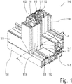
- Figure 1 shows a partial section of a lifting / sliding door 100 with a fixed leaf 110, a sliding leaf 120 and a threshold 130.
- the threshold 130 slopes outwards, where the fixed leaf is mounted, downwards.
- a height profile 140 is therefore arranged between the threshold 130 and the fixed wing 110 for height compensation.
- the fixed wing 110 and the sliding wing 120 are formed from the same profile, which is preferably a PVC-plastic profile.
- a large groove 112, 122 is provided in the profile cross section, which is used to accommodate several rollers in the lower section of the sliding sash 120.
- the grooves 112, 122 of the profile are closed on all sides where they are not required by cover profiles 113, 123.
- the sliding sash 120 is guided on a running rail 131 which is connected to the threshold 130.
- Another cover profile 132 is provided between the running rail 131 and the fixed wing 110.
- Figure 1 shows the closed position of the lift / slide door 100.
- the center seal profiles 111, 121 which are attached to the respective sections of the wings 110, 120, interlock.
- the end face of the middle seal profile 121 of the sliding sash 120 lies on a contact surface 16.1 on a middle seal block 10.
- the central seal block 10 thus serves to improve the sealing of the transition between the two wings 110, 120 and the threshold 130 in the closed state of the sliding wing 120.
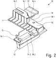
- a center seal block 10 shows Figure 2 .
- the center seal block 10 consists of a base 11 which extends in the longitudinal direction, that is to say parallel to the running rail 131, and a cross bar 12 connected at right angles thereto.
- the cross bar 12 ' has a connecting element 15 which fits into the structural profile 140 (cf. Fig. 1 ) can be inserted.
- Both the base 11 and the crossbar 12 each have contact surfaces 13, 14.1, 14.2 on their upper sides, which are covered with a thermoplastic elastomer.
- the contact surfaces 13, 14.2 also each have a filling opening 18.1, 18.2.
- a guide element 16 is integrally formed, which rises significantly above the contact surface 13. This has a contact surface 16.1 on its upper side, which is covered with an elastomeric layer.
- the guide element 16 has a groove 16.2 on its upper side, which opens towards the inside of the room, as also in FIG Figure 1 you can see.
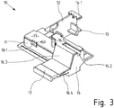
- FIG. 3 the center seal block 10 is shown from the other side. It can be seen here that the guide element 16 drops on an inclined surface 16.3 on the side facing the running rail 131. This is followed by an approximately horizontal support section 16.4. Sections 16.1, 16.3 and 16.4 are provided with a continuous elastomeric layer on the top, which consists, for example, of a thermoplastic elastomer applied in a two-component injection molding process. The support section 16.4 extends only a little beyond the outer contour of the center seal block 10 and the fixed wing 110 to the outside. However, the elastomeric layer applied thereon runs out in a sealing tab 17. Because no hard plastic structure is formed below the sealing tab 17, the latter can spring upwards when the fixed wing 110 is pivoted into the threshold and does not hinder the assembly movement.
- a continuous elastomeric layer on the top which consists, for example, of a thermoplastic elastomer applied in a two-component injection molding process.
- the support section 16.4 extends only a little beyond the
- FIG. 1 the center seal block 10 is shown in a top view of the underside.
- the middle seal block 10 is hollow on the underside.
- a sealing / adhesive chamber 19.1, 19.2 is formed on both the underside of the cross bar 12 and on the underside of the base 11, with each of the chambers 19.1,19.2 being assigned one of the filling openings 18.1,18.2.
- the two chambers 19.1, 19.2 are separated from one another by a transverse wall 19.3.
- Figure 5 shows a center seal end piece 20, of which in the assembled position of the lift and slide door 100 according to Figure 1 only one side edge of a base plate 23 can be seen.
- the middle seal end piece 20 is inserted from below into the middle seal profile 121, which is connected to the sliding sash 120.
- the base 23 has a few profile projections on the upper side, which allow insertion into the hollow plastic profile used as the central sealing profile 121.
- a spring 21 is formed on the underside of the base 23, and an inclined surface 22 on a pin 24 which projects downward beyond the base 23.
- FIG 6 is a section along the line AA in Figure 1 shown by the lift / slide door 100.
- the sliding sash 120 is raised more than it corresponds to the normal stroke in use.
- the relationships between the profiles in the area of the threshold and the center piece and the corresponding counterparts on the sliding sash 120 become clear.
- a sealing element 30 is arranged on the underside of the sliding sash 120, the contour of which is precisely matched to the running rail 131 and is covered with an elastomeric layer, so that the lowered sliding sash 120 presses against the elastic layer of the sealing element 30 when it is placed on the running rail 131, so that the seal is improved.
- part of the center seal block 10 can be seen between the fixed wing 110 and the running rail 131, namely the guide element 16 with the groove 16.2, the oblique flank 16.3 and the sealing tab 17.
- the counterpart to the sealing tab 17 consists in a closed profile section in the lower cross bar of the sliding leaf 120.
- a sealing connection is made when the sliding leaf 120 is lowered.
- center seal end piece 20 has been inserted from below. Its web 21 lies above the groove 16.2 and the inclined surface 22 lies plane-parallel to the inclined surface 16.3 on the guide element 16.
- Figure 7 shows the closed position of the lifting / sliding door 100, in which the sliding leaf 120 is lowered to the threshold 130.
- the sealing element 30 rests on the running rail 131.
- the profile of the sliding sash 120 lies on the sealing tab 17.
- the inclined surface 22 presses against the flank 16.3.
- the base 23 of the sealing end piece lies on the contact surface 16.1 of the Center seal block 10, and the web 21 engages in the groove 16.2 of the guide member 16.
- Fig. 8 shows the fixed wing 110 mounted on the threshold 130 in a similar view as in FIG Figure 1 , but here without the sliding sash. This shows how the contact surface 16.1 of the guide element 16 extends as far as the center seal profile 111.
- the elastomeric coating on the guide element 16 runs from the surface 16.1 over the inclined surface 16.3 to the sealing tab 17, the end of which rests on the edge of the running rail 131.
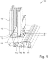
- FIG. 9 11 is another perspective view of the mounting condition of FIG Fig. 8 shown, but from the other side. It can be seen there how the center seal block 10 with its base 11 and the cross bar 12 extends continuously between the area of the threshold 130 located below the running rail 131.
- the fixed wing 110 stands with its lower end face on the elastomeric contact surface 14.1 on the crossbar 12 of the center seal block.
- the further contact area 14.2 serves to support the cover profile 113 (see Fig. 8 ) for the profile groove 112.
- the contact surface 13 serves as a seal with respect to the end face of the central seal profile 111 fastened on the outside to the fixed wing 110 (cf. Fig. 8 ).
- the contact surfaces 14.2, 13 are open, so that the position of the adhesive filling openings 18.1, 18.2 is visible.
- the dashed line marks the edge course of the finished bond between the underside of the center seal block 10 and the threshold 130.
Landscapes
- Engineering & Computer Science (AREA)
- Civil Engineering (AREA)
- Structural Engineering (AREA)
- Mechanical Engineering (AREA)
- Specific Sealing Or Ventilating Devices For Doors And Windows (AREA)
Claims (7)
- Système de bloc d'étanchéité central pour une porte levante et coulissante (100), comprenant au moins :- un bloc d'étanchéité central (10) devant être disposé entre un vantail fixe (110) et un profilé structurel (140) rehaussant un seuil de porte (130), comprenant au moins une base (11) qui s'étend, dans l'état monté, dans la direction longitudinale du profilé structurel (140), une traverse (12) qui se raccorde à angle droit à la base (11), au moins une chambre d'agent d'étanchéité/d'adhésif (19.1, 19.2) ouverte vers le bas étant réalisée au niveau d'un côté inférieur devant être tourné vers le profilé structurel (140), laquelle possède au moins une ouverture de remplissage (18.1, 18.2) s'ouvrant vers le côté supérieur ; caractérisé en ce que le système de bloc d'étanchéité central comprend- une pièce de bout d'étanchéité centrale (20) destinée à être insérée dans une extrémité frontale inférieure d'un profilé d'étanchéité central (121) devant être monté sur le vantail coulissant (120),- au moins une surface d'appui (13) étant réalisée au niveau de la base (11) du bloc d'étanchéité central, et un élément de guidage (16) dépassant par-dessus la surface d'appui (13) étant façonné au niveau de la base (11),- l'élément de guidage (16) possédant au niveau de son côté supérieur une surface d'appui (16.1) pour un profilé d'étanchéité central (121) du vantail coulissant (120), dans laquelle est réalisée au moins une rainure (16.2) s'étendant dans la direction longitudinale, et lequel élément de guidage présente au moins une surface oblique (16.3) au niveau d'un côté devant être tourné vers le vantail coulissant (120), et- la pièce de bout d'étanchéité centrale (20) présentant au moins une surface oblique (22) qui doit être disposée de manière plan-parallèle à la surface oblique (16.3) de l'élément de guidage (16).
- Système de bloc d'étanchéité central selon la revendication 1, caractérisé en ce qu'au moins une surface d'appui (23) et/ou une surface oblique (22) est/sont revêtue(s) au moins en partie d'une couche élastomère au niveau de la pièce de bout d'étanchéité centrale (20).
- Système de bloc d'étanchéité central selon la revendication 1 ou 2, caractérisé en ce que le côté supérieur (16.1) et/ou la surface d'appui (16.4) et/ou la surface oblique (16.3) de l'élément de guidage (16) est/sont revêtu(e) (s) au moins en partie d'une couche élastomère.
- Système de bloc d'étanchéité central selon l'une quelconque des revendications 1 à 3, caractérisé en ce que la traverse (12) et la base (11) présentent, au niveau de leurs côtés supérieurs devant être tournés vers le vantail fixe (110), à chaque fois au moins une surface d'appui (13 ; 14.1, 14.2), qui est à chaque fois revêtue au moins en partie d'une couche élastomère.
- Système de bloc d'étanchéité central selon l'une quelconque des revendications 1 à 4, caractérisé en ce qu'à chaque fois au moins une ouverture d'introduction d'un agent d'étanchéité/d'un adhésif (18.1, 18.2) est prévue au niveau de la base (11) et au niveau de la traverse (12).
- Système de bloc d'étanchéité central selon la revendication 5, caractérisé en ce que des chambres d'agent d'étanchéité/d'adhésif séparées l'une de l'autre (19.1, 19.2) sont réalisées au niveau du côté inférieur de la base (11) et au niveau du côté inférieur de la traverse (12).
- Système de bloc d'étanchéité central selon la revendication 6, caractérisé en ce qu'entre les chambres d'agent d'étanchéité/d'adhésif (19.1, 19.2) est prévue au moins une nervure (19.3) de hauteur réduite.
Priority Applications (1)
| Application Number | Priority Date | Filing Date | Title |
|---|---|---|---|
| PL17160692T PL3219893T3 (pl) | 2016-03-13 | 2017-03-13 | Blok uszczelki środkowej do drzwi podnoszono-przesuwnych |
Applications Claiming Priority (1)
| Application Number | Priority Date | Filing Date | Title |
|---|---|---|---|
| DE202016101390.9U DE202016101390U1 (de) | 2016-03-13 | 2016-03-13 | Mitteldichtungsblock und Mitteldichtungsblocksystem für eine Hebeschiebtür |
Publications (2)
| Publication Number | Publication Date |
|---|---|
| EP3219893A1 EP3219893A1 (fr) | 2017-09-20 |
| EP3219893B1 true EP3219893B1 (fr) | 2020-05-27 |
Family
ID=55974497
Family Applications (1)
| Application Number | Title | Priority Date | Filing Date |
|---|---|---|---|
| EP17160692.4A Active EP3219893B1 (fr) | 2016-03-13 | 2017-03-13 | Bloc d'étanchéité central pour une porte à levage coulissante |
Country Status (3)
| Country | Link |
|---|---|
| EP (1) | EP3219893B1 (fr) |
| DE (1) | DE202016101390U1 (fr) |
| PL (1) | PL3219893T3 (fr) |
Families Citing this family (5)
| Publication number | Priority date | Publication date | Assignee | Title |
|---|---|---|---|---|
| DE202017104217U1 (de) * | 2017-07-14 | 2018-07-17 | Grundmeier Kg | Schwellenhalter zum Befestigen eines Türrahmenprofils an einem Schwellenprofil |
| DE102022103403B4 (de) | 2022-02-14 | 2025-08-14 | HUECK System GmbH & Co. KG | Eckabdichtungselement |
| DE102023124131A1 (de) * | 2023-09-07 | 2025-03-13 | Maco Technologie Gmbh | Bodenschwelle |
| DE102023124130A1 (de) * | 2023-09-07 | 2025-03-13 | Maco Technologie Gmbh | Bodenschwelle |
| DE102023130835A1 (de) * | 2023-11-07 | 2025-05-08 | VEKA Aktiengesellschaft | Dichtungssystem und Schiebetür |
Family Cites Families (3)
| Publication number | Priority date | Publication date | Assignee | Title |
|---|---|---|---|---|
| DE202007015160U1 (de) * | 2007-10-30 | 2009-03-12 | Frey, Inge | Türrahmen mit einer Bodenschwelle |
| DE202008013043U1 (de) | 2008-10-02 | 2009-02-12 | Gretsch-Unitas GmbH Baubeschläge | Hebe-Schiebe-Fenster oder -Tür sowie Abdichtelement |
| DE102013107650A1 (de) * | 2013-07-18 | 2015-01-22 | Aluplast Gmbh | Mitteldichtungsblock für Hebe-Schiebe-Tür- oder Fenster |
-
2016
- 2016-03-13 DE DE202016101390.9U patent/DE202016101390U1/de not_active Expired - Lifetime
-
2017
- 2017-03-13 EP EP17160692.4A patent/EP3219893B1/fr active Active
- 2017-03-13 PL PL17160692T patent/PL3219893T3/pl unknown
Non-Patent Citations (1)
| Title |
|---|
| None * |
Also Published As
| Publication number | Publication date |
|---|---|
| EP3219893A1 (fr) | 2017-09-20 |
| DE202016101390U1 (de) | 2016-04-29 |
| PL3219893T3 (pl) | 2020-11-16 |
Similar Documents
| Publication | Publication Date | Title |
|---|---|---|
| EP3219893B1 (fr) | Bloc d'étanchéité central pour une porte à levage coulissante | |
| EP3259428B1 (fr) | Dispositif d'étanchéité pour éléments de fenêtre et éléments de porte | |
| EP2754842B1 (fr) | Profil d'étanchéité pour un profil de cadre et profil de cadre | |
| DE69509450T2 (de) | Seitenscheibe mit hohenverstellbarer Position für Kraftfahrzeuge | |
| DE102017002243A1 (de) | Fahrzeugtür | |
| AT518469A2 (de) | Dichtung und Fensterelement | |
| AT413293B (de) | Schiebeelement-dichtung | |
| EP2947229B1 (fr) | Fenêtre de toit et procédé de montage d'une fenêtre de toit | |
| DE102020131475A1 (de) | Wassertasse für eine Fensterbank sowie Fenstersystem mit einer solchen Wassertasse | |
| DE10207157B4 (de) | Verbindungselement zur stirnseitigen Verbindung von zwei Teilen | |
| DE102011001283B4 (de) | Türanordnung | |
| EP3141687B1 (fr) | Joint d'etancheite antiretour d'une porte | |
| EP4001575B1 (fr) | Espaceur | |
| EP3715576B1 (fr) | Pièce d'assemblage de seuil universelle pourvue d'élément interchangeable | |
| AT518432B1 (de) | Dichtungsvorrichtung mit bewegbarer Dichtleiste | |
| EP2362047B1 (fr) | Porte à levage coulissante ou fenêtre à levage coulissant | |
| EP2599946B1 (fr) | Dispositif d'étanchéité pour une zone de bord central d'un agencement de châssis coulissant ainsi qu'agencement de châssis coulissant avec un dispositif d'étanchéité | |
| EP3530861A1 (fr) | Élément horizontal de cadre pour un cadre de porte coulissante et / ou de fenêtre coulissante, cadre de porte coulissante et / ou de fenêtre coulissante ainsi que système de porte coulissante et / ou de fenêtre coulissante | |
| DE202012007784U1 (de) | Zargenkonstruktion | |
| DE102020103603B4 (de) | Hochwasserbeständiges Sektionaltor | |
| DE20306546U1 (de) | Türdichtungsschwelle | |
| EP3318710B1 (fr) | Système de seuil de porte | |
| EP3299569B1 (fr) | Fenêtre de toît | |
| DE102023130835A1 (de) | Dichtungssystem und Schiebetür | |
| DE102015115067A1 (de) | Hinterlaufsichere Abdichtung einer Tür gegenüber einem Baukörper |
Legal Events
| Date | Code | Title | Description |
|---|---|---|---|
| PUAI | Public reference made under article 153(3) epc to a published international application that has entered the european phase |
Free format text: ORIGINAL CODE: 0009012 |
|
| STAA | Information on the status of an ep patent application or granted ep patent |
Free format text: STATUS: THE APPLICATION HAS BEEN PUBLISHED |
|
| AK | Designated contracting states |
Kind code of ref document: A1 Designated state(s): AL AT BE BG CH CY CZ DE DK EE ES FI FR GB GR HR HU IE IS IT LI LT LU LV MC MK MT NL NO PL PT RO RS SE SI SK SM TR |
|
| AX | Request for extension of the european patent |
Extension state: BA ME |
|
| STAA | Information on the status of an ep patent application or granted ep patent |
Free format text: STATUS: REQUEST FOR EXAMINATION WAS MADE |
|
| 17P | Request for examination filed |
Effective date: 20180320 |
|
| RBV | Designated contracting states (corrected) |
Designated state(s): AL AT BE BG CH CY CZ DE DK EE ES FI FR GB GR HR HU IE IS IT LI LT LU LV MC MK MT NL NO PL PT RO RS SE SI SK SM TR |
|
| STAA | Information on the status of an ep patent application or granted ep patent |
Free format text: STATUS: EXAMINATION IS IN PROGRESS |
|
| 17Q | First examination report despatched |
Effective date: 20181128 |
|
| GRAP | Despatch of communication of intention to grant a patent |
Free format text: ORIGINAL CODE: EPIDOSNIGR1 |
|
| STAA | Information on the status of an ep patent application or granted ep patent |
Free format text: STATUS: GRANT OF PATENT IS INTENDED |
|
| INTG | Intention to grant announced |
Effective date: 20200110 |
|
| GRAS | Grant fee paid |
Free format text: ORIGINAL CODE: EPIDOSNIGR3 |
|
| GRAA | (expected) grant |
Free format text: ORIGINAL CODE: 0009210 |
|
| STAA | Information on the status of an ep patent application or granted ep patent |
Free format text: STATUS: THE PATENT HAS BEEN GRANTED |
|
| AK | Designated contracting states |
Kind code of ref document: B1 Designated state(s): AL AT BE BG CH CY CZ DE DK EE ES FI FR GB GR HR HU IE IS IT LI LT LU LV MC MK MT NL NO PL PT RO RS SE SI SK SM TR |
|
| REG | Reference to a national code |
Ref country code: GB Ref legal event code: FG4D Free format text: NOT ENGLISH |
|
| REG | Reference to a national code |
Ref country code: CH Ref legal event code: EP |
|
| REG | Reference to a national code |
Ref country code: AT Ref legal event code: REF Ref document number: 1274713 Country of ref document: AT Kind code of ref document: T Effective date: 20200615 |
|
| REG | Reference to a national code |
Ref country code: DE Ref legal event code: R096 Ref document number: 502017005414 Country of ref document: DE |
|
| REG | Reference to a national code |
Ref country code: NL Ref legal event code: FP |
|
| REG | Reference to a national code |
Ref country code: CH Ref legal event code: NV Representative=s name: SCHMAUDER AND PARTNER AG PATENT- UND MARKENANW, CH |
|
| REG | Reference to a national code |
Ref country code: LT Ref legal event code: MG4D |
|
| PG25 | Lapsed in a contracting state [announced via postgrant information from national office to epo] |
Ref country code: GR Free format text: LAPSE BECAUSE OF FAILURE TO SUBMIT A TRANSLATION OF THE DESCRIPTION OR TO PAY THE FEE WITHIN THE PRESCRIBED TIME-LIMIT Effective date: 20200828 Ref country code: NO Free format text: LAPSE BECAUSE OF FAILURE TO SUBMIT A TRANSLATION OF THE DESCRIPTION OR TO PAY THE FEE WITHIN THE PRESCRIBED TIME-LIMIT Effective date: 20200827 Ref country code: LT Free format text: LAPSE BECAUSE OF FAILURE TO SUBMIT A TRANSLATION OF THE DESCRIPTION OR TO PAY THE FEE WITHIN THE PRESCRIBED TIME-LIMIT Effective date: 20200527 Ref country code: PT Free format text: LAPSE BECAUSE OF FAILURE TO SUBMIT A TRANSLATION OF THE DESCRIPTION OR TO PAY THE FEE WITHIN THE PRESCRIBED TIME-LIMIT Effective date: 20200928 Ref country code: IS Free format text: LAPSE BECAUSE OF FAILURE TO SUBMIT A TRANSLATION OF THE DESCRIPTION OR TO PAY THE FEE WITHIN THE PRESCRIBED TIME-LIMIT Effective date: 20200927 Ref country code: SE Free format text: LAPSE BECAUSE OF FAILURE TO SUBMIT A TRANSLATION OF THE DESCRIPTION OR TO PAY THE FEE WITHIN THE PRESCRIBED TIME-LIMIT Effective date: 20200527 Ref country code: FI Free format text: LAPSE BECAUSE OF FAILURE TO SUBMIT A TRANSLATION OF THE DESCRIPTION OR TO PAY THE FEE WITHIN THE PRESCRIBED TIME-LIMIT Effective date: 20200527 |
|
| PG25 | Lapsed in a contracting state [announced via postgrant information from national office to epo] |
Ref country code: HR Free format text: LAPSE BECAUSE OF FAILURE TO SUBMIT A TRANSLATION OF THE DESCRIPTION OR TO PAY THE FEE WITHIN THE PRESCRIBED TIME-LIMIT Effective date: 20200527 Ref country code: LV Free format text: LAPSE BECAUSE OF FAILURE TO SUBMIT A TRANSLATION OF THE DESCRIPTION OR TO PAY THE FEE WITHIN THE PRESCRIBED TIME-LIMIT Effective date: 20200527 Ref country code: BG Free format text: LAPSE BECAUSE OF FAILURE TO SUBMIT A TRANSLATION OF THE DESCRIPTION OR TO PAY THE FEE WITHIN THE PRESCRIBED TIME-LIMIT Effective date: 20200827 Ref country code: RS Free format text: LAPSE BECAUSE OF FAILURE TO SUBMIT A TRANSLATION OF THE DESCRIPTION OR TO PAY THE FEE WITHIN THE PRESCRIBED TIME-LIMIT Effective date: 20200527 |
|
| PG25 | Lapsed in a contracting state [announced via postgrant information from national office to epo] |
Ref country code: AL Free format text: LAPSE BECAUSE OF FAILURE TO SUBMIT A TRANSLATION OF THE DESCRIPTION OR TO PAY THE FEE WITHIN THE PRESCRIBED TIME-LIMIT Effective date: 20200527 |
|
| PG25 | Lapsed in a contracting state [announced via postgrant information from national office to epo] |
Ref country code: ES Free format text: LAPSE BECAUSE OF FAILURE TO SUBMIT A TRANSLATION OF THE DESCRIPTION OR TO PAY THE FEE WITHIN THE PRESCRIBED TIME-LIMIT Effective date: 20200527 Ref country code: CZ Free format text: LAPSE BECAUSE OF FAILURE TO SUBMIT A TRANSLATION OF THE DESCRIPTION OR TO PAY THE FEE WITHIN THE PRESCRIBED TIME-LIMIT Effective date: 20200527 Ref country code: SM Free format text: LAPSE BECAUSE OF FAILURE TO SUBMIT A TRANSLATION OF THE DESCRIPTION OR TO PAY THE FEE WITHIN THE PRESCRIBED TIME-LIMIT Effective date: 20200527 Ref country code: DK Free format text: LAPSE BECAUSE OF FAILURE TO SUBMIT A TRANSLATION OF THE DESCRIPTION OR TO PAY THE FEE WITHIN THE PRESCRIBED TIME-LIMIT Effective date: 20200527 Ref country code: EE Free format text: LAPSE BECAUSE OF FAILURE TO SUBMIT A TRANSLATION OF THE DESCRIPTION OR TO PAY THE FEE WITHIN THE PRESCRIBED TIME-LIMIT Effective date: 20200527 |
|
| PG25 | Lapsed in a contracting state [announced via postgrant information from national office to epo] |
Ref country code: SK Free format text: LAPSE BECAUSE OF FAILURE TO SUBMIT A TRANSLATION OF THE DESCRIPTION OR TO PAY THE FEE WITHIN THE PRESCRIBED TIME-LIMIT Effective date: 20200527 |
|
| REG | Reference to a national code |
Ref country code: DE Ref legal event code: R097 Ref document number: 502017005414 Country of ref document: DE |
|
| PLBE | No opposition filed within time limit |
Free format text: ORIGINAL CODE: 0009261 |
|
| STAA | Information on the status of an ep patent application or granted ep patent |
Free format text: STATUS: NO OPPOSITION FILED WITHIN TIME LIMIT |
|
| 26N | No opposition filed |
Effective date: 20210302 |
|
| PG25 | Lapsed in a contracting state [announced via postgrant information from national office to epo] |
Ref country code: SI Free format text: LAPSE BECAUSE OF FAILURE TO SUBMIT A TRANSLATION OF THE DESCRIPTION OR TO PAY THE FEE WITHIN THE PRESCRIBED TIME-LIMIT Effective date: 20200527 |
|
| PG25 | Lapsed in a contracting state [announced via postgrant information from national office to epo] |
Ref country code: MC Free format text: LAPSE BECAUSE OF FAILURE TO SUBMIT A TRANSLATION OF THE DESCRIPTION OR TO PAY THE FEE WITHIN THE PRESCRIBED TIME-LIMIT Effective date: 20200527 |
|
| GBPC | Gb: european patent ceased through non-payment of renewal fee |
Effective date: 20210313 |
|
| PG25 | Lapsed in a contracting state [announced via postgrant information from national office to epo] |
Ref country code: LU Free format text: LAPSE BECAUSE OF NON-PAYMENT OF DUE FEES Effective date: 20210313 Ref country code: IE Free format text: LAPSE BECAUSE OF NON-PAYMENT OF DUE FEES Effective date: 20210313 Ref country code: GB Free format text: LAPSE BECAUSE OF NON-PAYMENT OF DUE FEES Effective date: 20210313 |
|
| PGFP | Annual fee paid to national office [announced via postgrant information from national office to epo] |
Ref country code: RO Payment date: 20220303 Year of fee payment: 6 |
|
| PG25 | Lapsed in a contracting state [announced via postgrant information from national office to epo] |
Ref country code: HU Free format text: LAPSE BECAUSE OF FAILURE TO SUBMIT A TRANSLATION OF THE DESCRIPTION OR TO PAY THE FEE WITHIN THE PRESCRIBED TIME-LIMIT; INVALID AB INITIO Effective date: 20170313 |
|
| PG25 | Lapsed in a contracting state [announced via postgrant information from national office to epo] |
Ref country code: CY Free format text: LAPSE BECAUSE OF FAILURE TO SUBMIT A TRANSLATION OF THE DESCRIPTION OR TO PAY THE FEE WITHIN THE PRESCRIBED TIME-LIMIT Effective date: 20200527 |
|
| P01 | Opt-out of the competence of the unified patent court (upc) registered |
Effective date: 20230528 |
|
| PG25 | Lapsed in a contracting state [announced via postgrant information from national office to epo] |
Ref country code: RO Free format text: LAPSE BECAUSE OF NON-PAYMENT OF DUE FEES Effective date: 20230313 |
|
| PG25 | Lapsed in a contracting state [announced via postgrant information from national office to epo] |
Ref country code: MK Free format text: LAPSE BECAUSE OF FAILURE TO SUBMIT A TRANSLATION OF THE DESCRIPTION OR TO PAY THE FEE WITHIN THE PRESCRIBED TIME-LIMIT Effective date: 20200527 |
|
| PG25 | Lapsed in a contracting state [announced via postgrant information from national office to epo] |
Ref country code: TR Free format text: LAPSE BECAUSE OF FAILURE TO SUBMIT A TRANSLATION OF THE DESCRIPTION OR TO PAY THE FEE WITHIN THE PRESCRIBED TIME-LIMIT Effective date: 20200527 |
|
| PG25 | Lapsed in a contracting state [announced via postgrant information from national office to epo] |
Ref country code: MT Free format text: LAPSE BECAUSE OF FAILURE TO SUBMIT A TRANSLATION OF THE DESCRIPTION OR TO PAY THE FEE WITHIN THE PRESCRIBED TIME-LIMIT Effective date: 20200527 |
|
| PGFP | Annual fee paid to national office [announced via postgrant information from national office to epo] |
Ref country code: IT Payment date: 20250331 Year of fee payment: 9 |
|
| PGFP | Annual fee paid to national office [announced via postgrant information from national office to epo] |
Ref country code: CH Payment date: 20250401 Year of fee payment: 9 |
|
| REG | Reference to a national code |
Ref country code: CH Ref legal event code: U11 Free format text: ST27 STATUS EVENT CODE: U-0-0-U10-U11 (AS PROVIDED BY THE NATIONAL OFFICE) Effective date: 20260401 |
|
| PGFP | Annual fee paid to national office [announced via postgrant information from national office to epo] |
Ref country code: DE Payment date: 20260320 Year of fee payment: 10 |
|
| PGFP | Annual fee paid to national office [announced via postgrant information from national office to epo] |
Ref country code: AT Payment date: 20260319 Year of fee payment: 10 |
|
| PGFP | Annual fee paid to national office [announced via postgrant information from national office to epo] |
Ref country code: BE Payment date: 20260323 Year of fee payment: 10 |
|
| PGFP | Annual fee paid to national office [announced via postgrant information from national office to epo] |
Ref country code: NL Payment date: 20260323 Year of fee payment: 10 |
|
| PGFP | Annual fee paid to national office [announced via postgrant information from national office to epo] |
Ref country code: FR Payment date: 20260325 Year of fee payment: 10 |
|
| PGFP | Annual fee paid to national office [announced via postgrant information from national office to epo] |
Ref country code: PL Payment date: 20260227 Year of fee payment: 10 |