EP3219904A1 - Procédé d'intervention sans tube-guide - Google Patents
Procédé d'intervention sans tube-guide Download PDFInfo
- Publication number
- EP3219904A1 EP3219904A1 EP16160230.5A EP16160230A EP3219904A1 EP 3219904 A1 EP3219904 A1 EP 3219904A1 EP 16160230 A EP16160230 A EP 16160230A EP 3219904 A1 EP3219904 A1 EP 3219904A1
- Authority
- EP
- European Patent Office
- Prior art keywords
- lubricator
- tool string
- waterline
- pipe
- lubricator pipe
- Prior art date
- Legal status (The legal status is an assumption and is not a legal conclusion. Google has not performed a legal analysis and makes no representation as to the accuracy of the status listed.)
- Withdrawn
Links
Images




Classifications
-
- E—FIXED CONSTRUCTIONS
- E21—EARTH OR ROCK DRILLING; MINING
- E21B—EARTH OR ROCK DRILLING; OBTAINING OIL, GAS, WATER, SOLUBLE OR MELTABLE MATERIALS OR A SLURRY OF MINERALS FROM WELLS
- E21B19/00—Handling rods, casings, tubes or the like outside the borehole, e.g. in the derrick; Apparatus for feeding the rods or cables
- E21B19/002—Handling rods, casings, tubes or the like outside the borehole, e.g. in the derrick; Apparatus for feeding the rods or cables specially adapted for underwater drilling
-
- E—FIXED CONSTRUCTIONS
- E21—EARTH OR ROCK DRILLING; MINING
- E21B—EARTH OR ROCK DRILLING; OBTAINING OIL, GAS, WATER, SOLUBLE OR MELTABLE MATERIALS OR A SLURRY OF MINERALS FROM WELLS
- E21B33/00—Sealing or packing boreholes or wells
- E21B33/02—Surface sealing or packing
- E21B33/03—Well heads; Setting-up thereof
- E21B33/068—Well heads; Setting-up thereof having provision for introducing objects or fluids into, or removing objects from, wells
- E21B33/076—Well heads; Setting-up thereof having provision for introducing objects or fluids into, or removing objects from, wells specially adapted for underwater installations
Definitions
- the present invention relates to a riserless intervention method for offshore intervention of a well from a vessel by means of a tool string, the vessel having a waterline.
- a riser When performing a subsea intervention of a well where a tool string is submerged into the well to perform an operation, a riser is often installed at the top of the well from a vessel, and the tool string is subsequently assembled and submerged into the riser.
- setting up a riser takes approximately 90 days, and a vessel with sufficient capacity is rarely available with a few days' notice, and the operation thus requires more time for planning. Therefore, a riserless solution has been developed where a lubricator pipe is installed above a blowout preventer on the well head or Christmas tree. The tool string is then mounted on the vessel using a grease head and submerged into the water where it enters the lubricator pipe.
- the grease head is mounted on top of the lubricator pipe and encloses the tool in the lubricator pipe. Then, a flushing system surrounding the lubricator pipe exchanges the seawater in the lubricator pipe with glycol or ethylene glycol, and the lubricator pipe is subsequently pressurised and valves in the top of the well are opened and the intervention operation can occur.
- the vessel has a derrick or a large crane for handling the 60 feet or longer tool string.
- a vessel capable of handling such long tool strings and lubricator pipes is one of the larger vessels, meaning that more planning is required and higher rental costs are involved.
- the riserless intervention method described above may further comprise the step of introducing the tool string in a lubricator pipe.
- the riserless intervention method may comprise the steps of submerging a first end of a first lubricator part of a lubricator pipe below the waterline so that a second end of the first lubricator part extends above the waterline; arranging a second lubricator part on top of the first lubricator part; and connecting a first end of the second lubricator part to the second end of the first lubricator part.
- the tool string may be submerged into the lubricator pipe.
- the riserless intervention method described above may further comprise the step of connecting a grease head to the lubricator pipe above the waterline.
- the lubricator pipe may be connected with a top of the well.
- the lubricator pipe may be connected with the top of the well while the tool string is arranged within the lubricator pipe.
- the riserless intervention method described above may further comprise the step of arranging the tool string or the lubricator pipe in a suspension unit so that movements of the vessel are absorbed by the suspension unit.
- the riserless intervention method described above according to any may further comprise the step of disconnecting the lubricator pipe from the top of the well.
- the riserless intervention method may further comprise the step of pulling the lubricator pipe at least partly above the waterline.
- the riserless intervention method may further comprise the step of disconnecting the parts of the tool string.
- the riserless intervention method may further comprise the step of disconnecting the parts of the lubricator pipe.
- the riserless intervention method may further comprise the step of closing the end of the lubricator pipe closest to the top of the well.
- the lubricator pipe By closing the end of the lubricator pipe closest to the top of the well, the lubricator pipe is sealed from below, and its content is thereby brought to surface.
- the vessel has a mounting height above the waterline which is smaller than a length of the tool string or a length of the lubricator pipe.
- the riserless intervention method described above may further comprise the step of connecting a first end of a third part of the tool string to a second end of the second part of the tool string above the waterline.
- the riserless intervention method may further comprise the step of connecting a first end of a third lubricator part of the lubricator pipe to a second end of the second lubricator part of the lubricator pipe above the waterline.
- the riserless intervention method may further comprise the step of introducing the tool string into the well to perform the intervention.
- the riserless intervention method may further comprise the step of moving the tool string back into the lubricator pipe.
- the riserless intervention method may further comprise the step of opening a valve in a blowout preventer, a Christmas tree or a well head.
- the riserless intervention method may further comprise the step of opening a tool catcher.
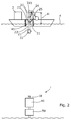
- Fig. 1 shows a well 1 about to be intervened from a vessel 2 by an intervention tool 3 in the form of a tool string 3 comprising at least a first part 6 and a second part 8.
- the tool string 3 is lowered into a lubricator pipe 20 mounted on e.g. a blowout preventer 40 or directly on a Christmas tree 50 forming a top 10 of the well 1.
- the tool string 3 is mounted from the vessel 2 which is a small vessel having a mounting height smaller than a length of the lubricator pipe 20 and/or the tool string.
- the tool string 3 is mounted by submerging a first end 5 of the first part 6 of the tool string 3 below the waterline 4 of the vessel 2 so that a second end 7 of the first part extends above the waterline and is suspended in a suspension unit 31.
- the vessel 2 may have a moon pool 41 into which the tool part is lowered, or the tool string may be lowered over the side of the vessel (not shown).
- the second part 8 of the tool string 3 is arranged on top of the first part 6 of the tool string by a second suspension unit 31b, and a first end 9 of the second part 8 of the tool string is connected with the second end 7 of the first part of the tool string above the waterline 4 while the remaining part of the first part is below the waterline.
- the mounting height of the vessel 2 can be substantially reduced, which eliminates the a need for a large vessel, which in turn substantially reduces costs related to renting a vessel and further reduces the time needed for planning and performing the operation.
- the length of the tool string 3 is no longer restricted by the mounting height available on the vessel 2, and the tool string can now in theory be mounted with an endless length.
- the second part 8 of the tool string 3 is partly submerged into the water and a first end 11 of a third part 12 of the tool string is mounted to a second end 14 of the second part 8 of the tool string. Subsequently, further parts can be mounted on top of the third part 12 in the same manner by first partly submerging the previously mounted part below the waterline and then connecting the further part thereto until the entire tool string is assembled. Then, the tool string 3 can be introduced into a lubricator pipe 20.
- a lubricator pipe 20 is mounted from the vessel 2 having a mounting height H smaller than a length of the lubricator pipe 20.
- the mounting height extends from the deck of the waterline 4 of the vessel 2 to the summit of the highest possible reach of the lubricator pipe or tool string in the upward direction.
- the lubricator pipe 20 is mounted by submerging a first end 21 of a first lubricator part 22 of the lubricator pipe 20 below the waterline 4 so that a second end 23 of the first lubricator part is above the waterline.
- a second lubricator part 24 is arranged on top of the first lubricator part 22 and a first end 25 of the second lubricator part is connected to the second end 23 of the first lubricator part.
- the lubricator pipe 20 is submerged into the sea and is connected to the top 10 of the well 1.
- the lubricator pipe may be maintained while being suspended in the suspension unit 31 of the vessel 2 while the tool string 3 is mounted, as shown in Fig. 3 where the first end of the first part 6 of the tool string 3 is submerged below the waterline 4 of the vessel into the lubricator pipe 20 so that the second end 7 of the first part 6 extends above the waterline 4 and is suspended in a third suspension unit 31a while the second part 8 of the tool string is suspended in the second suspension unit 31b.
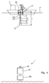
- a grease head 30 is connected to the lubricator pipe above the waterline 4, as shown in Fig. 4
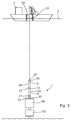
- the lubricator pipe is connected with the top 10 of the well 1, as shown in Fig. 5 .
- the lubricator pipe is connected with the top 10 of the well 1 while the tool string is arranged within the lubricator pipe.
- the tool string or the lubricator pipe is arranged in a suspension unit 31 which may be a gyroscopic suspension unit causing movements of the vessel 2 to be absorbed by the suspension unit.
- the tool string 3 After performing an intervention operation by means of the tool string, e.g. pulling a crown plug or milling out a safety valve, the tool string 3 re-enters the lubricator pipe and is fastened in a tool catcher 32 (shown in Fig. 5 ). Then, the valves in top 10 of the well 1, e.g. in the blowout preventer, are closed and the lubricator pipe is disconnected from the top 10 of the well 1. Before the lubricator pipe is disconnected, a closing unit 33 may be closed, thereby closing an opening (not shown) in the first end of the first lubricator part arranged closest to the top 10 of the well 1 so that the fluid inside the lubricator pipe remains therein while the pipe is brought to surface.
- a closing unit 33 may be closed, thereby closing an opening (not shown) in the first end of the first lubricator part arranged closest to the top 10 of the well 1 so that the fluid inside the lubricator pipe remains therein while the pipe is brought to surface.
- the grease head 30 (shown in Fig. 5 ) is then disconnected and the tool string is dismounted part by part by pulling the lubricator pipe partly above the waterline 4 while it is still suspended from the vessel 2.
- the dirty fluid is kept in the lubricator pipe when the tool string is reconstructed or re-rigged, and the grease head 30 is subsequently re-mounted and the lubricator pipe with the tool string is mounted for another operation.
- the tool string is disconnected part by part, and subsequently, the lubricator pipe is disconnected part by part until all the lubricator parts are above the waterline.
- the end of the lubricator pipe closest to the top 10 of the well 1 is closed by closing the closing unit 33 (shown in Fig. 6 ) and the lubricator pipe is filled with glycol or ethylene glycol so that the fluid inside the lubricator pipe does not freeze if the temperature is sufficiently low when the intervention is performed.
- the second end 28 of the second lubricator part 24 is partly submerged into the water and a first end 26 of a third lubricator part 27 of the lubricator pipe is mounted to a second end 28 of the second lubricator part 24.
- further lubricator parts can be mounted on top of the third lubricator part in the same manner by first partly submerging the previously mounted part below the waterline and then connecting the further part thereto until the entire lubricator pipe has been assembled.
- the tool string may comprise several parts and operational tools arranged in the end facing the well.
- the parts of the tool string may be a stroker tool for pulling a crown plug, a key tool for moving a sliding sleeve, a milling tool for milling out a safety valve, etc.
- a stroking tool is a tool providing an axial force.
- the stroking tool comprises an electrical motor for driving a pump.
- the pump pumps fluid into a piston housing to move a piston acting therein.
- the piston is arranged on the stroker shaft.
- the pump may pump fluid into the piston housing on one side and simultaneously suck fluid out on the other side of the piston.
- fluid or well fluid any kind of fluid that may be present in oil or gas wells downhole, such as natural gas, oil, oil mud, crude oil, water, etc.
- gas is meant any kind of gas composition present in a well, completion, or open hole
- oil is meant any kind of oil composition, such as crude oil, an oil-containing fluid, etc.
- Gas, oil, and water fluids may thus all comprise other elements or substances than gas, oil, and/or water, respectively.
- a downhole tractor can be used to push the tool all the way into position in the well.
- the downhole tractor may have projectable arms having wheels, wherein the wheels contact the inner surface of the casing for propelling the tractor and the tool forward in the casing.
- a downhole tractor is any kind of driving tool capable of pushing or pulling tools in a well downhole, such as a Well Tractor®.
- a casing any kind of pipe, tubing, tubular, liner, string etc. used downhole in relation to oil or natural gas production.
Landscapes
- Engineering & Computer Science (AREA)
- Life Sciences & Earth Sciences (AREA)
- Geology (AREA)
- Mining & Mineral Resources (AREA)
- Physics & Mathematics (AREA)
- Environmental & Geological Engineering (AREA)
- Fluid Mechanics (AREA)
- General Life Sciences & Earth Sciences (AREA)
- Geochemistry & Mineralogy (AREA)
- Mechanical Engineering (AREA)
- Earth Drilling (AREA)
Priority Applications (5)
| Application Number | Priority Date | Filing Date | Title |
|---|---|---|---|
| EP16160230.5A EP3219904A1 (fr) | 2016-03-14 | 2016-03-14 | Procédé d'intervention sans tube-guide |
| US16/082,390 US10801295B2 (en) | 2016-03-14 | 2017-03-13 | Riserless intervention system and method |
| DK17709458.8T DK3430232T3 (da) | 2016-03-14 | 2017-03-13 | Stigrørsløst interventionssystem og fremgangsmåde |
| EP17709458.8A EP3430232B1 (fr) | 2016-03-14 | 2017-03-13 | Système d'intervention sans tube-guide |
| PCT/EP2017/055845 WO2017157854A1 (fr) | 2016-03-14 | 2017-03-13 | Système et procédé d'intervention sans colonne montante |
Applications Claiming Priority (1)
| Application Number | Priority Date | Filing Date | Title |
|---|---|---|---|
| EP16160230.5A EP3219904A1 (fr) | 2016-03-14 | 2016-03-14 | Procédé d'intervention sans tube-guide |
Publications (1)
| Publication Number | Publication Date |
|---|---|
| EP3219904A1 true EP3219904A1 (fr) | 2017-09-20 |
Family
ID=55527490
Family Applications (1)
| Application Number | Title | Priority Date | Filing Date |
|---|---|---|---|
| EP16160230.5A Withdrawn EP3219904A1 (fr) | 2016-03-14 | 2016-03-14 | Procédé d'intervention sans tube-guide |
Country Status (1)
| Country | Link |
|---|---|
| EP (1) | EP3219904A1 (fr) |
Citations (3)
| Publication number | Priority date | Publication date | Assignee | Title |
|---|---|---|---|---|
| US3987910A (en) * | 1975-02-07 | 1976-10-26 | Siro Brunato | Apparatus for racking drill pipes on floater type platforms |
| US6250395B1 (en) * | 1999-11-05 | 2001-06-26 | Carlos A. Torres | Apparatus system and method for installing and retrieving pipe in a well |
| US20110203803A1 (en) * | 2000-08-14 | 2011-08-25 | Warren Zemlak | Apparatus for subsea intervention |
-
2016
- 2016-03-14 EP EP16160230.5A patent/EP3219904A1/fr not_active Withdrawn
Patent Citations (3)
| Publication number | Priority date | Publication date | Assignee | Title |
|---|---|---|---|---|
| US3987910A (en) * | 1975-02-07 | 1976-10-26 | Siro Brunato | Apparatus for racking drill pipes on floater type platforms |
| US6250395B1 (en) * | 1999-11-05 | 2001-06-26 | Carlos A. Torres | Apparatus system and method for installing and retrieving pipe in a well |
| US20110203803A1 (en) * | 2000-08-14 | 2011-08-25 | Warren Zemlak | Apparatus for subsea intervention |
Similar Documents
| Publication | Publication Date | Title |
|---|---|---|
| EP2185784B1 (fr) | Pompe montée sur ligne de retour pour système de retour de boue sans colonne de montée | |
| US8689879B2 (en) | Fluid displacement methods and apparatus for hydrocarbons in subsea production tubing | |
| AU2004203372B2 (en) | ROV retrievable sea floor pump | |
| US5533574A (en) | Dual concentric string high pressure riser | |
| AU2015350412B2 (en) | Subsea slanted wellhead system and bop system with dual injector head units | |
| US8826989B2 (en) | Method for capping a well in the event of subsea blowout preventer failure | |
| EP2744970B1 (fr) | Module de pompe de liquide de forage couplé à un segment de tube prolongateur présentant une configuration spéciale et procédé de couplage du module de pompe au tube prolongateur | |
| US20130126182A1 (en) | Riserless, pollutionless drilling system | |
| NO20191012A1 (en) | An apparatus for forming at least a part of a production system for a wellbore, and a line for and a method of performing an operation to set a cement plug in a wellbore | |
| US6672390B2 (en) | Systems and methods for constructing subsea production wells | |
| US20220307322A1 (en) | Maritime drilling with fluid reverse circulation without using drilling riser | |
| WO2007133929A2 (fr) | Procédé et système de récupération d'un tube prolongateur lors d'une évacuation en cas de tempête | |
| EP2890861B1 (fr) | Systèmes de déplacement et de nettoyage de colonne montante et leurs procédés d'utilisation | |
| EP3219904A1 (fr) | Procédé d'intervention sans tube-guide | |
| EP3430232B1 (fr) | Système d'intervention sans tube-guide | |
| Moreira et al. | Guideline/ess Completions Offshore Brazil | |
| EP3219905A1 (fr) | Système d'intervention sans tube-guide | |
| WO2018031296A1 (fr) | Procédé d'assemblage et de désassemblage de la colonne montante marine et des lignes auxiliaires ainsi que système de commande de la pression du puits | |
| NO20160250A1 (en) | Device for enabling removal or installation of a horizontal Christmas tree and methods thereof | |
| US9488018B2 (en) | Fluid displacement tool and method | |
| WO2010050827A1 (fr) | Raccord en y pour relier une tête de puits sous-marine à une colonne montante | |
| WO2005005770A1 (fr) | Systemes et procedes de construction de puits de production sous-marins | |
| Humphrey et al. | North Sea Marginal Fields: The Subsea Completions Option | |
| NO340649B1 (en) | Improvements in particular relating to wellbore circulation operations |
Legal Events
| Date | Code | Title | Description |
|---|---|---|---|
| PUAI | Public reference made under article 153(3) epc to a published international application that has entered the european phase |
Free format text: ORIGINAL CODE: 0009012 |
|
| AK | Designated contracting states |
Kind code of ref document: A1 Designated state(s): AL AT BE BG CH CY CZ DE DK EE ES FI FR GB GR HR HU IE IS IT LI LT LU LV MC MK MT NL NO PL PT RO RS SE SI SK SM TR |
|
| AX | Request for extension of the european patent |
Extension state: BA ME |
|
| STAA | Information on the status of an ep patent application or granted ep patent |
Free format text: STATUS: THE APPLICATION IS DEEMED TO BE WITHDRAWN |
|
| 18D | Application deemed to be withdrawn |
Effective date: 20180321 |