EP3219946A1 - Système d'injection d'eau d'urée et procédé pour empêcher la cristallisation dans un dispositif d'injection d'eau d'urée - Google Patents
Système d'injection d'eau d'urée et procédé pour empêcher la cristallisation dans un dispositif d'injection d'eau d'urée Download PDFInfo
- Publication number
- EP3219946A1 EP3219946A1 EP15859438.2A EP15859438A EP3219946A1 EP 3219946 A1 EP3219946 A1 EP 3219946A1 EP 15859438 A EP15859438 A EP 15859438A EP 3219946 A1 EP3219946 A1 EP 3219946A1
- Authority
- EP
- European Patent Office
- Prior art keywords
- water solution
- urea water
- injection device
- solution injection
- crystal
- Prior art date
- Legal status (The legal status is an assumption and is not a legal conclusion. Google has not performed a legal analysis and makes no representation as to the accuracy of the status listed.)
- Withdrawn
Links
Images

Classifications
-
- B—PERFORMING OPERATIONS; TRANSPORTING
- B01—PHYSICAL OR CHEMICAL PROCESSES OR APPARATUS IN GENERAL
- B01D—SEPARATION
- B01D53/00—Separation of gases or vapours; Recovering vapours of volatile solvents from gases; Chemical or biological purification of waste gases, e.g. engine exhaust gases, smoke, fumes, flue gases, aerosols
- B01D53/34—Chemical or biological purification of waste gases
- B01D53/74—General processes for purification of waste gases; Apparatus or devices specially adapted therefor
- B01D53/86—Catalytic processes
- B01D53/90—Injecting reactants
-
- F—MECHANICAL ENGINEERING; LIGHTING; HEATING; WEAPONS; BLASTING
- F01—MACHINES OR ENGINES IN GENERAL; ENGINE PLANTS IN GENERAL; STEAM ENGINES
- F01N—GAS-FLOW SILENCERS OR EXHAUST APPARATUS FOR MACHINES OR ENGINES IN GENERAL; GAS-FLOW SILENCERS OR EXHAUST APPARATUS FOR INTERNAL-COMBUSTION ENGINES
- F01N3/00—Exhaust or silencing apparatus having means for purifying, rendering innocuous, or otherwise treating exhaust
- F01N3/08—Exhaust or silencing apparatus having means for purifying, rendering innocuous, or otherwise treating exhaust for rendering innocuous
- F01N3/10—Exhaust or silencing apparatus having means for purifying, rendering innocuous, or otherwise treating exhaust for rendering innocuous by thermal or catalytic conversion of noxious components of exhaust
- F01N3/18—Exhaust or silencing apparatus having means for purifying, rendering innocuous, or otherwise treating exhaust for rendering innocuous by thermal or catalytic conversion of noxious components of exhaust characterised by methods of operation; Control
- F01N3/20—Exhaust or silencing apparatus having means for purifying, rendering innocuous, or otherwise treating exhaust for rendering innocuous by thermal or catalytic conversion of noxious components of exhaust characterised by methods of operation; Control specially adapted for catalytic conversion
- F01N3/206—Adding periodically or continuously substances to exhaust gases for promoting purification, e.g. catalytic material in liquid form, NOx reducing agents
- F01N3/208—Control of selective catalytic reduction [SCR], e.g. by adjusting the dosing of reducing agent
-
- B—PERFORMING OPERATIONS; TRANSPORTING
- B01—PHYSICAL OR CHEMICAL PROCESSES OR APPARATUS IN GENERAL
- B01D—SEPARATION
- B01D53/00—Separation of gases or vapours; Recovering vapours of volatile solvents from gases; Chemical or biological purification of waste gases, e.g. engine exhaust gases, smoke, fumes, flue gases, aerosols
- B01D53/34—Chemical or biological purification of waste gases
- B01D53/92—Chemical or biological purification of waste gases of engine exhaust gases
- B01D53/94—Chemical or biological purification of waste gases of engine exhaust gases by catalytic processes
- B01D53/9404—Removing only nitrogen compounds
- B01D53/9409—Nitrogen oxides
- B01D53/9413—Processes characterised by a specific catalyst
- B01D53/9418—Processes characterised by a specific catalyst for removing nitrogen oxides by selective catalytic reduction [SCR] using a reducing agent in a lean exhaust gas
-
- B—PERFORMING OPERATIONS; TRANSPORTING
- B01—PHYSICAL OR CHEMICAL PROCESSES OR APPARATUS IN GENERAL
- B01D—SEPARATION
- B01D53/00—Separation of gases or vapours; Recovering vapours of volatile solvents from gases; Chemical or biological purification of waste gases, e.g. engine exhaust gases, smoke, fumes, flue gases, aerosols
- B01D53/34—Chemical or biological purification of waste gases
- B01D53/92—Chemical or biological purification of waste gases of engine exhaust gases
- B01D53/94—Chemical or biological purification of waste gases of engine exhaust gases by catalytic processes
- B01D53/9404—Removing only nitrogen compounds
- B01D53/9409—Nitrogen oxides
- B01D53/9431—Processes characterised by a specific device
-
- B—PERFORMING OPERATIONS; TRANSPORTING
- B01—PHYSICAL OR CHEMICAL PROCESSES OR APPARATUS IN GENERAL
- B01D—SEPARATION
- B01D53/00—Separation of gases or vapours; Recovering vapours of volatile solvents from gases; Chemical or biological purification of waste gases, e.g. engine exhaust gases, smoke, fumes, flue gases, aerosols
- B01D53/34—Chemical or biological purification of waste gases
- B01D53/92—Chemical or biological purification of waste gases of engine exhaust gases
- B01D53/94—Chemical or biological purification of waste gases of engine exhaust gases by catalytic processes
- B01D53/9495—Controlling the catalytic process
-
- F—MECHANICAL ENGINEERING; LIGHTING; HEATING; WEAPONS; BLASTING
- F01—MACHINES OR ENGINES IN GENERAL; ENGINE PLANTS IN GENERAL; STEAM ENGINES
- F01N—GAS-FLOW SILENCERS OR EXHAUST APPARATUS FOR MACHINES OR ENGINES IN GENERAL; GAS-FLOW SILENCERS OR EXHAUST APPARATUS FOR INTERNAL-COMBUSTION ENGINES
- F01N3/00—Exhaust or silencing apparatus having means for purifying, rendering innocuous, or otherwise treating exhaust
- F01N3/08—Exhaust or silencing apparatus having means for purifying, rendering innocuous, or otherwise treating exhaust for rendering innocuous
-
- F—MECHANICAL ENGINEERING; LIGHTING; HEATING; WEAPONS; BLASTING
- F01—MACHINES OR ENGINES IN GENERAL; ENGINE PLANTS IN GENERAL; STEAM ENGINES
- F01N—GAS-FLOW SILENCERS OR EXHAUST APPARATUS FOR MACHINES OR ENGINES IN GENERAL; GAS-FLOW SILENCERS OR EXHAUST APPARATUS FOR INTERNAL-COMBUSTION ENGINES
- F01N3/00—Exhaust or silencing apparatus having means for purifying, rendering innocuous, or otherwise treating exhaust
- F01N3/08—Exhaust or silencing apparatus having means for purifying, rendering innocuous, or otherwise treating exhaust for rendering innocuous
- F01N3/10—Exhaust or silencing apparatus having means for purifying, rendering innocuous, or otherwise treating exhaust for rendering innocuous by thermal or catalytic conversion of noxious components of exhaust
- F01N3/18—Exhaust or silencing apparatus having means for purifying, rendering innocuous, or otherwise treating exhaust for rendering innocuous by thermal or catalytic conversion of noxious components of exhaust characterised by methods of operation; Control
-
- B—PERFORMING OPERATIONS; TRANSPORTING
- B01—PHYSICAL OR CHEMICAL PROCESSES OR APPARATUS IN GENERAL
- B01D—SEPARATION
- B01D2251/00—Reactants
- B01D2251/20—Reductants
- B01D2251/206—Ammonium compounds
- B01D2251/2067—Urea
-
- F—MECHANICAL ENGINEERING; LIGHTING; HEATING; WEAPONS; BLASTING
- F01—MACHINES OR ENGINES IN GENERAL; ENGINE PLANTS IN GENERAL; STEAM ENGINES
- F01N—GAS-FLOW SILENCERS OR EXHAUST APPARATUS FOR MACHINES OR ENGINES IN GENERAL; GAS-FLOW SILENCERS OR EXHAUST APPARATUS FOR INTERNAL-COMBUSTION ENGINES
- F01N2610/00—Adding substances to exhaust gases
- F01N2610/02—Adding substances to exhaust gases the substance being ammonia or urea
-
- F—MECHANICAL ENGINEERING; LIGHTING; HEATING; WEAPONS; BLASTING
- F01—MACHINES OR ENGINES IN GENERAL; ENGINE PLANTS IN GENERAL; STEAM ENGINES
- F01N—GAS-FLOW SILENCERS OR EXHAUST APPARATUS FOR MACHINES OR ENGINES IN GENERAL; GAS-FLOW SILENCERS OR EXHAUST APPARATUS FOR INTERNAL-COMBUSTION ENGINES
- F01N2610/00—Adding substances to exhaust gases
- F01N2610/10—Adding substances to exhaust gases the substance being heated, e.g. by heating tank or supply line of the added substance
- F01N2610/105—Control thereof
-
- F—MECHANICAL ENGINEERING; LIGHTING; HEATING; WEAPONS; BLASTING
- F01—MACHINES OR ENGINES IN GENERAL; ENGINE PLANTS IN GENERAL; STEAM ENGINES
- F01N—GAS-FLOW SILENCERS OR EXHAUST APPARATUS FOR MACHINES OR ENGINES IN GENERAL; GAS-FLOW SILENCERS OR EXHAUST APPARATUS FOR INTERNAL-COMBUSTION ENGINES
- F01N2610/00—Adding substances to exhaust gases
- F01N2610/14—Arrangements for the supply of substances, e.g. conduits
- F01N2610/1453—Sprayers or atomisers; Arrangement thereof in the exhaust apparatus
- F01N2610/146—Control thereof, e.g. control of injectors or injection valves
Definitions
- the present invention relates to, in a urea water solution injection system for an internal combustion engine, a urea water solution injection system which can prevent crystallization of urea water solution and a sticking of urea inside the urea water injection device and a method for preventing crystallization in the urea water injection device.
- an exhaust emission control system including a urea water solution injection system and a selective catalytic reduction catalyst (SCR catalyst) device in combination is provided to remove NOx (nitrogen oxides) contained in exhaust gas discharged from the internal combustion engine.
- SCR catalyst selective catalytic reduction catalyst
- a urea water solution is sprayed into the exhaust gas which passes through an interior of an exhaust passageway from a urea water solution injection device (a dosing valve: DV) which is provided on a portion of the exhaust passageway which is disposed on an upstream side of the selective catalytic reduction catalyst device to thereby produce ammonia (NH 3 ) from the urea water solution, and NOx contained in exhaust gas is reduced by the use of the ammonia so produced in the selective catalytic reduction catalyst device to thereby reduce NOx from the exhaust gas.
- a urea water solution injection device a dosing valve: DV
- urea water solution injection device used together with the selective catalytic reduction catalyst device
- an emptying operation is performed in which a urea water solution remaining in a urea water solution piping is returned to a urea water solution tank. Since the urea water solution injection device is fully opened in performing the emptying operation, high temperature exhaust gas within the exhaust pipe pass through the urea water solution injection device, whereby the interior of the urea water solution injection device is heated to high temperatures once.
- the temperature inside the urea water solution injection device decreases moderately, and a slight amount of urea water solution which remains inside the urea water solution injection device is frozen to be crystallized as the temperature inside the urea water solution injection device so decreases. Since a needle of the urea water solution injection device is stuck therein and cannot move any more when the urea water solution is frozen to be crystallized, urea water solution cannot be sprayed when the engine is restarted.
- JP-A-2014-145276 proposes a urea water solution piping closure detection apparatus for SCR using urea for detecting accurately whether or not a piping from a urea water solution supply pump to a dosing valve (a urea water solution injection device) for spraying a urea water solution is closed.
- This urea water solution piping closure detection apparatus for urea SCR includes a closure determination unit for detecting the clogging of the piping from a detection value of a pressure sensor for detecting a pressure in a urea water solution return line through which a urea water solution is returned under pressure when an emptying control in which a urea water solution remaining in the piping is returned to a urea water solution tank is performed by performing a start-up control in which a supply pump is driven to raise the pressure in the piping when an engine starter key is switched on and thereafter performing the emptying control when a detection value of an exhaust gas temperature sensor which is provided on a portion of an exhaust passageway which is disposed upstream of an SCR catalyst device is equal to or lower than a preset temperature and a detection value of a urea water solution sensor for detecting the temperature of a urea water solution in the urea water solution tank is equal to or higher than a freezing temperature.
- a thawing device is driven to cause an engine coolant to flow to the urea water solution tank and the dosing valve to thaw the urea water solution frozen in the tank and the valve when the temperature of the urea water solution which is detected by the urea water solution sensor is equal to or lower than the freezing temperature (although depending upon the concentration of the urea water solution, -11°C with a normal concentration of 32.5%), there still remains a problem that the engine coolant at its normal temperature can thaw only the frozen urea water solution but cannot dissolve the urea which is crystallized in the dosing valve.
- JP-A-2013-221425 proposes an injector control device for an exhaust emission control system for promoting the thawing of a frozen urea water solution by heating the whole of an injector (a urea water solution injector) which sprays a urea water solution when it is supplied with an electric current of equal to or greater than an upper limit electric current value by heating an electromagnetic drive unit of the injector by supplying the electromagnetic drive unit with an electric current of smaller than the upper limit electric current value which prevents the spray of a urea water solution by the injector when the temperature of a urea water solution which is supplied to the injector is lower than a preset lower limit temperature in order to avoid an addition of a urea water solution at other timings than a predetermined timing, while promoting the thawing of the frozen urea water solution.
- an injector a urea water solution injector
- the injector control device intends to promote the thawing of the frozen urea water solution, and there still remains a problem that by the electric current that is smaller than the upper limit current value which cannot open, the injector control device can only thaw the frozen urea water solution but cannot dissolve the urea which is formed in the interior of the injector as a result of the urea water solution being frozen to be crystallized.
- JP-A-2011-247135 proposes an SCR system including a sticking prevention system for preventing the sticking of urea water solution formed as a result of the urea water solution being frozen to be crystallized.
- the sticking prevention system performs a sticking preventing control in which in such a state that the temperature of exhaust gas in an exhaust passageway is lower than an SCR catalyst activation temperature, when the exhaust gas temperature is equal to or higher than a urea water solution crystallization temperature , the sticking prevention system opens a dosing valve to prevent the sticking of urea formed inside the dosing valve as a result of the crystallization of the urea water solution and performs an emptying operation of returning the urea water solution in the dosing valve to a urea water solution tank by controlling a supply unit so as to suck the exhaust gas in the exhaust passageway into an interior of the dosing valve to thereby remove the urea water solution before it is frozen to be crystall
- an object of the invention is to provide a urea water solution injection system and a urea water solution crystallization prevention method for a urea water solution injection device which can dissolve urea formed in the urea water solution injection device as a result of a urea water solution being frozen to be crystallized when an internal combustion engine is started so as to prevent the sticking of the urea in the urea water solution injection device to thereby prevent a failure thereof.
- a urea water solution injection system comprising a urea water solution injection device for spraying a urea water solution into a portion of an exhaust passageway upstream of a selective catalytic reduction catalyst device to reduce NOx contained in exhaust gas discharged from an internal combustion engine, in which an engine coolant is circulated through the urea water solution injection device to prevent the freezing of the urea water solution
- a control device for controlling the urea water solution injection system comprises a crystal dissolution control unit for performing a crystal dissolution control on the urea water solution injection device by energizing at a preset amount of energization at a state where a urea water solution supply pump for supplying a urea water solution to the urea water solution injection device is kept stopped, and wherein after the engine is started but before a urea water solution is started to be supplied, the control device is configured to control the crystal dissolution control unit to perform the crystal dissolution control for a crystal
- the urea water solution injection device before the urea water solution is started to be supplied after the internal combustion engine is started, not only can the frozen urea water solution be thawed but also the urea crystallized in the interior of the urea water solution injection device can be dissolved by heating the urea water solution injection device using the engine coolant which flows through the interior thereof, energizing a coil for moving a needle (a plunger) of the urea water solution injection device and the synergistic effect of heating the urea water solution injection device by using the engine coolant and energizing the coil.
- the urea water solution injection device which would otherwise be caused by the crystallized urea.
- the control device includes a sticking state determination unit for determining whether or not the urea water solution injection device is in a sticking state by energizing the urea water solution injection device at the state where the urea water solution supply pump is kept stopped, and after the engine is started but before a urea water solution is started to be supplied, the crystal dissolution control unit performs the crystal dissolution control for the crystal dissolving energization time that is calculated in advance, and a preset stopping time has elapsed, the sticking state determination unit determines whether or not the urea water solution injection device is in the sticking state, and when it is determined that the urea water solution injection device is not in the sticking state, a urea water solution is sprayed into the portion of the exhaust passageway upstream of the selective catalytic reduction catalyst device by using the urea water solution injection device in accordance with a urea water solution supply request.
- the sticking state determination unit determines that the urea water solution injection device is not in a sticking state after the internal combustion engine is started but before the urea water solution is started to be supplied, it is determined whether or not the urea water solution injection device fails before the urea water solution is started to be supplied, whereby it is possible to prevent the running of the internal combustion engine in such a state that NOx is reduced insufficiently.
- the determination on whether or not the urea water solution injection device is in a sticking state is made by determining on a change ratio of a driving current of the urea water solution injection device (DV).
- the control device includes an energization time calculation unit for calculating the crystal dissolving energization time based on any of or a combination of some of engine coolant temperature, outside air temperature and exhaust gas temperature.
- the crystallized urea can be dissolved efficiently in a minimum time and with a minimum heat value required for dissolution of the crystallized urea, whereby the sticking of the urea water solution injection device due to the crystallized urea can be prevented.
- the crystal dissolving energization time is set in advance through experiments based on engine coolant temperature, outside air temperature and exhaust gas temperature and is stored in the control unit in the form of a data map. Then, a crystal dissolving energization time is calculated by referring to the data map stored during control.
- the control device is configured to: when it is determined by the sticking state determination unit, the determination being made after the engine is started but before the urea water solution is started to be supplied, that the urea water solution injection device is in the sticking state, before a urea water solution is started to be sprayed, control the crystal dissolution control unit to further perform the crystal dissolution control for a newly calculated crystal dissolving energization time, control the sticking state determination unit to make the determination, and repeat a cycle of the crystal dissolution control by the crystal dissolution control unit and the determination made thereafter by the sticking state determination unit until it is determined that the urea water solution injection device is not in the sticking state; when the number of times of repeating the cycle exceeds a preset determination number of times of repeating the cycle, determine that failure occurs in the urea water solution device; and when it is determined that the urea water solution injection device is not in the sticking state during a time period at which the number of times of repeating the cycle is equal to
- the series of controls including the crystal dissolution control is performed repeatedly until the preset number of times of repeating the cycle which is set for determination is reached after the internal combustion engine is started but before the urea water solution is started to be supplied, the urea crystallized in the interior of the urea water solution injection device can be dissolved in a more ensured fashion, whereby the sticking of the urea water solution injection device due to the crystallized urea can be prevented.
- the crystal dissolution control unit corrects the crystal dissolving energization time based on the number of times of repeating the cycle. According to this configuration, it is possible to perform a renewed crystal dissolution control which matches a change in temperature in the interior of the urea water solution injection device which is caused by the repetition of the crystal dissolution control. Therefore, it is possible to dissolve the crystallized urea with good efficiency while avoiding a risk of the urea water solution injection device being heated to high temperatures.
- a method for preventing crystallization in a urea water solution injection device of a urea water solution injection system which comprises the urea water solution injection device for spraying the urea water solution into a portion of an exhaust passageway upstream of a selective catalytic reduction catalyst device to reduce NOx contained in exhaust gas discharged from an internal combustion engine, and in which an engine coolant is circulated through the urea water solution injection device to prevent the freezing of the urea water solution
- the method including: after the engine is started but before a urea water solution is started to be supplied, for a crystal dissolving energization time that is calculated based on any of or a combination of some of engine coolant temperature, outside air temperature and exhaust gas temperature, performing control of dissolving a crystal on the urea water solution injection device by energizing at a preset amount of energization at a state where a urea water solution supply pump for supplying
- the crystallized urea can be dissolved after the internal combustion engine is started but before the urea water solution is started to be supplied, whereby the failure of the urea water solution injection device can be prevented by preventing the sticking of the urea water solution injection device.
- a urea water solution injection system of the embodiment of the invention includes a urea water solution injection device for spraying a urea water solution into a portion of an exhaust passageway which is disposed upstream of a selective catalytic reduction catalyst device to reduce NOx in exhaust gas discharged from an internal combustion engine. Additionally, an engine coolant is circulated to pass through the urea water solution injection device so as to prevent the freezing of a urea water solution.
- a control unit 10 which controls the urea water solution injection system includes an energization time calculation unit 11, a crystal dissolution control unit 12 and a sticking state determination unit 13.
- This energization time calculation unit 11 calculates a crystal dissolving energization time which is a period of time during which a coil in an interior of the urea water solution injection device is energized to dissolve urea which is formed in the urea water solution injection device as a result of a urea water solution being frozen to be crystallized based on any of engine coolant temperature, outside air temperature and exhaust gas temperature or a combination of some of them.
- the energization time calculation unit 11 allows the urea formed as a result of crystallization of the urea water solution to be solved in a minimum time and with a minimum heat value which are required for solution of urea formed through crystallization of the urea water solution, whereby the sticking of the urea water solution injection device due to the crystallized urea can be prevented with a required minimum amount of electric energy.
- This crystal dissolving energization time is set in advance through experiments based on engine coolant temperature, outside air temperature and exhaust gas temperature and is stored in the control unit in the form of a data map. Then, the energization time calculation unit 11 calculates a crystal dissolving energization time by referring to the data map stored during control.
- This crystal dissolving energization time normally takes a value which falls within a range of the order of 300s or shorter. In a special case where the engine coolant temperature, the outside air temperature and the exhaust gas temperature are high enough for the crystallized urea to be dissolved under natural conditions without being energized, the urea crystal dissolving energization time is set at zero.
- the crystal dissolution control unit 12 performs a crystal dissolution control in which the crystal dissolution control unit 12 energizes the urea water solution injection device with a preset amount of energization with a urea water solution supply pump for supplying a urea water solution to the urea water solution injection device kept stopped.
- the crystal dissolution control unit 12 can enable the urea water solution injection device to be heated by not only using an engine coolant of the order of 70°C which flows through an interior thereof but also energizing a coil for moving a needle (a plunger) of the urea water solution injection device, not only can the frozen urea water solution be thawed but also the urea crystallized in the interior of the urea water solution injection device can be dissolved by the synergistic effect of heating the urea water solution injection device by using the engine coolant and energizing the coil.
- An amount of energization which enables the urea water solution injection device to be fully opened may be used for the amount of energization (the energization per unit time) of the coil.
- an optimum amount of energization is obtained in advance through experiments and that the amount of energization of the coil is set at the optimum amount of energization. Since this amount of energization of the coil is also related to the crystal dissolving energization time, the amount of energization of the coil may be caused to change with the crystal dissolution energizing time.
- the amount of energization is normally in the range of the order of 100% to 5% of the amount of energization by which the urea water solution injection device is opened fully.
- the sticking state determination unit 13 determines whether or not the urea water solution injection device is in a sticking state by energizing the urea water solution injection device with the urea water solution supply pump kept stopped. This sticking state determination unit 13 enables a selection between repeating the crystal dissolution control and making a determination that the urea water solution injection device does not stick due to the crystallized urea. The determination on the sticking state of the urea water solution injection device can be made based on a change ratio of a driving current of the urea water solution injection device (DV).
- control unit 10 which controls the urea water solution injection system is configured so that the crystal dissolution control unit 12 performs the crystal dissolution control during the crystal dissolving energization time which is calculated in advance by the energization time calculation unit 11 after the engine is started but before the urea water solution is started to be supplied.
- the frozen urea water solution be thawed but also the urea crystallized in the interior of the urea water solution injection device can be dissolved by heating the urea water solution injection device using the engine coolant which flows through the interior thereof, energizing the coil for moving the needle (the plunger) of the urea water solution injection device and the synergistic effect of heating the urea water solution injection device by using the engine coolant and energizing the coil.
- the sticking state determination unit 13 determines whether or not the urea water solution injection device is in a sticking state after a preset stopping time has elapsed since the end of the crystal dissolution control. In case it is determined that the urea water solution injection device is not in a sticking state, the urea water solution injection device sprays the urea water solution into a portion of an exhaust passageway which is disposed upstream of a selective crystal reduction catalyst device in response to a urea water solution supply request.
- the stopping time may be set at zero, since the thermal inertia of the energization of the coil can be made use of, it should preferably be avoided that the stopping time is set at such a long time as that the urea water solution injection device is cooled to lose the heating effect by the energization thereof.
- the stopping time is set in advance through experiments. Normally, the stopping time takes a numerical value which falls within a range of the order of 10s or shorter.
- the crystal dissolution control unit 12 performs further the crystal dissolution control during a crystal dissolving energization time which is newly calculated, whereafter, the sticking state determination unit 13 makes a determination. Then, this cycle of the performing of the crystal dissolution control by the crystal dissolution control unit 12 and the determination by the determination unit 13 made thereafter will be repeated until the sticking state determination unit 13 determines that the urea water solution injection device is not in a sticking state.
- the determination unit 13 determines that the urea water solution injection device fails, whereas in case the determination unit 13 determines that the urea water solution injection device is not in a sticking state on or before the arrival of the number of times of repeating the cycle at the preset number of times of determination, the urea water solution injection device sprays the urea water solution into the portion of the exhaust passageway which is disposed upstream of the selective catalytic reduction catalyst device in response to the urea water solution supply request.
- the number of times of determination is set at the order of 3 to 6 times, for example.
- the crystal dissolution control unit 12 corrects the crystal dissolving energization time based on the number of times of repeating the cycle, and by doing so, it is possible to perform a renewed crystal dissolution control which matches a change in temperature in the interior of the urea water solution injection device which is caused by the repetition of the crystal dissolution control. Therefore, it is possible to dissolve the crystallized urea with good efficiency while avoiding a risk of the urea water solution injection device being heated to high temperatures.
- a method of correcting the crystal dissolving energization time by the crystal dissolution control unit 12 is set in advance through experiments.
- This urea water solution crystallization prevention method is provided for the urea water solution injection system which includes the urea water solution injection device for spraying the urea water solution into the portion of the exhaust passageway which is disposed upstream of the selective catalytic reduction catalyst device to reduce NOx contained in the exhaust gas discharged from the internal combustion engine and in which the engine coolant is circulated through the urea water solution injection device to prevent the freezing of the urea water solution therein.
- a urea crystal dissolution control is performed on the urea water solution injection device in which the urea water solution injection device is energized with a preset amount of energization for the crystal dissolving energization time which is calculated based on any one of or a combination of some of engine coolant temperature, outside air temperature and exhaust gas temperature after the engine is started but before the urea water solution is started to be supplied with the urea water solution supply pump kept stopped which supplies the urea water solution to the urea water solution injection device.
- the urea water solution injection device is energized with the urea water solution supply pump kept stopped after a preset stopping time has elapsed, and a first series of controls is performed to determine whether or not the urea water solution injection device is in a sticking state.
- the amount of energization becomes maximum when the urea water solution injection device is fully opened, and the heat value thereof increases accordingly.
- it is preferable that an amount of energization which is good enough to dissolve a crystal of urea is obtained in advance through experiments for use for the amount of energization.
- a urea water solution is sprayed into the portion of the exhaust passageway which is disposed upstream of the selective catalytic reduction catalyst device in response to a urea water solution supply request by using the urea water solution injection device.
- a further crystal dissolving energization time is calculated based on any one of or a combination of some of engine coolant temperature, outside air temperature and exhaust gas temperature, and a second series of crystal dissolution controls is performed on the urea water solution injection device in which the urea water solution injection device is energized with the previous preset amount of energization or a new preset amount of energization for the further crystal dissolving energization time with the urea water solution supply pump kept stopped.
- This new preset amount of energization may be the same as the previous preset amount of energization. However, in consideration of the fact that the temperature of the urea water solution injection device is increased by the previous energization, it is preferable that the new preset amount of energization is smaller than the previous preset amount of energization.
- the urea water solution injection device is energized with the urea water solution supply pump driven after a preset stopping time has elapsed which is the same as the previous preset stopping time or a newly preset one, and it is determined then whether or not the urea water solution injection device is in a sticking state.
- the crystallized urea can be dissolved more efficiently by determining the stopping time in consideration of the history of temperature increases in the urea water solution injection device.
- a urea water solution is sprayed into the portion of the exhaust passageway which is disposed upstream of the selective catalytic reduction catalyst device in response to a urea water solution supply request by using the urea water solution injection device.
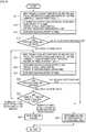
- the urea water solution crystallization prevention method of the embodiment can be performed by following a control flow as shown in Fig. 2 .
- the control flow shown in Fig. 2 is called for from a host control flow and is then started.
- step S11 an engine coolant temperature, an outside sir temperature and an exhaust gas temperature are inputted, and a crystal dissolving energization time is calculated based on any one of or a combination of some of these temperatures. Additionally, the number of times of repeating the cycle is set at one time.
- step S12 it is confirmed that the urea water solution supply pump for supplying a urea water solution to the urea water solution injection device is stopped.
- the pump is then stopped.
- the urea water solution injection device is energized with the preset amount of energization for the crystal dissolving energization time which is calculated in step S 11, and the urea crystal dissolution control is performed.
- step S13 the energization is stopped to wait until the preset stopping time is elapsed. After this waiting time is elapsed, in step S 14, the urea water solution injection device is energized with the urea water solution supply pump kept stopped, and it is then determined whether or not the urea water solution injection device is in a sticking state.
- step S 14 If it is determined by the determination made in step S 14 that the urea water solution injection device is not in a sticking state, the control flow proceeds to step S30, where understanding that the crystallized urea is dissolved, a signal which signals the dissolution of the crystallized urea is issued. Thereafter, the control flow returns to the host control flow, where the urea water solution injection device sprays a urea water solution into the portion of the exhaust passageway which is disposed upstream of the selective catalytic reduction catalyst device in response to the urea water solution supply request to reduce NOx contained in the exhaust gas.
- step S 21 an engine coolant temperature, an outside air temperature and an exhaust gas temperature are inputted, and a new crystal dissolving energization time is calculated based on any one of or a combination of some of these temperatures. The number of times of repeating the cycle is increased by one from the previous number of times of repeating the cycle.
- step S22 the urea water solution injection device is energized for the crystal dissolving energization time which is calculated in step S21, and the urea crystal dissolution control is performed.
- step S23 the energization is stopped to wait until the preset stopping time is elapsed. After this waiting time is elapsed, in the next step, that is, in step S24, the urea water solution injection device is energized with the urea water solution supply pump kept stopped, and it is then determined whether or not the urea water solution injection device is in a sticking state.
- step S24 If it is determined by the determination made in step S24 that the urea water solution injection device is not in a sticking state, the control flow proceeds to step S30, where understanding that the crystallized urea is dissolved, a signal which signals the dissolution of the crystallized urea is issued. Thereafter, the control flow returns to the host control flow, where the urea water solution injection device sprays a urea water solution into the portion of the exhaust passageway which is disposed upstream of the selective catalytic reduction catalyst device in response to the urea water solution supply request to reduce NOx contained in the exhaust gas.
- step S24 if it is determined in step S24 that the urea water solution injection device is in a sticking state, the control flow proceeds to step S27.
- step S25 it is determined whether or not the number of times of repeating the cycle exceeds the preset number of times of repeating the cycle which is set for determination.
- step S25 If it is determined by the determination made in step S25 that the number of times of repeating the cycle does not exceed the number of times of repeating the cycle which is set for determination, the control flow returns to step S21. If it is determined that the number of times of repeating the cycle exceeds the number of times of repeating the cycle which is set for determination, the control flow proceeds to step S40, and it is determined that failure occurs in the urea water solution injection device, and a failure signal is issued. Then, the control flow returns to the host control flow. A urea water solution is supplied to reduce NOx. By these controls, the above-described crystallization prevention method for the urea water solution injection device can be performed.
- the urea water solution injection system and the urea water solution crystallization prevention method for a urea water solution injection device of the invention since the crystal dissolution control continues to be performed until it is determined that the urea water solution injection device is not in a sticking state after the internal combustion engine is started but before the urea water solution is started to be supplied, the urea crystallized in the interior of the urea water solution injection device can be dissolved further, whereby the sticking of the urea water solution injection device due to the crystallized urea can be prevented.
- the series of controls including the crystal dissolution control is performed repeatedly until the preset number of times of repeating the cycle which is set for determination is reached after the internal combustion engine is started but before the urea water solution is started to be supplied, the urea crystallized in the interior of the urea water solution injection device can be dissolved in a more ensured fashion, whereby the sticking of the urea water solution injection device due to the crystallized urea can be prevented.
- the urea water solution injection device fails when the number of times of performing of the crystal dissolution controls exceeds the number of times of repeating the cycle which is set for determination, it is possible to detect a failure of the urea water solution injection device which is attributed to other causes than the sticking thereof due to the crystallized urea therein to enhance the precision of failure detection.
- the crystallized urea can be dissolved after the internal combustion engine is started but before the urea water solution is started to be supplied, whereby the failure of the urea water solution injection device can be prevented by preventing the sticking of the urea water solution injection device.
- the drawback can be eliminated in which the urea water solution cannot be sprayed due to the needle of the urea water solution injection device being unable to move due to the crystallized urea
- the case where the urea water solution injection device is erroneously misunderstood to fail due to the crystallization of the urea water solution can be excluded from a list of failure causes, whereby it is possible to prevent the erroneous removal of the urea water solution injection device from the urea water solution injection system which does not fail in reality and which is then recovered to its normal state when the crystallized urea is dissolved.
Landscapes
- Engineering & Computer Science (AREA)
- Chemical & Material Sciences (AREA)
- Chemical Kinetics & Catalysis (AREA)
- Health & Medical Sciences (AREA)
- Combustion & Propulsion (AREA)
- Environmental & Geological Engineering (AREA)
- Biomedical Technology (AREA)
- Analytical Chemistry (AREA)
- General Chemical & Material Sciences (AREA)
- Oil, Petroleum & Natural Gas (AREA)
- Mechanical Engineering (AREA)
- General Engineering & Computer Science (AREA)
- Toxicology (AREA)
- Exhaust Gas After Treatment (AREA)
- Exhaust Gas Treatment By Means Of Catalyst (AREA)
Applications Claiming Priority (2)
| Application Number | Priority Date | Filing Date | Title |
|---|---|---|---|
| JP2014230611A JP2016094863A (ja) | 2014-11-13 | 2014-11-13 | 尿素水噴射システム及び尿素水噴射装置の結晶化防止方法 |
| PCT/JP2015/081458 WO2016076256A1 (fr) | 2014-11-13 | 2015-11-09 | Système d'injection d'eau d'urée et procédé pour empêcher la cristallisation dans un dispositif d'injection d'eau d'urée |
Publications (2)
| Publication Number | Publication Date |
|---|---|
| EP3219946A1 true EP3219946A1 (fr) | 2017-09-20 |
| EP3219946A4 EP3219946A4 (fr) | 2018-07-04 |
Family
ID=55954341
Family Applications (1)
| Application Number | Title | Priority Date | Filing Date |
|---|---|---|---|
| EP15859438.2A Withdrawn EP3219946A4 (fr) | 2014-11-13 | 2015-11-09 | Système d'injection d'eau d'urée et procédé pour empêcher la cristallisation dans un dispositif d'injection d'eau d'urée |
Country Status (5)
| Country | Link |
|---|---|
| US (1) | US10450922B2 (fr) |
| EP (1) | EP3219946A4 (fr) |
| JP (1) | JP2016094863A (fr) |
| CN (1) | CN107109982B (fr) |
| WO (1) | WO2016076256A1 (fr) |
Cited By (1)
| Publication number | Priority date | Publication date | Assignee | Title |
|---|---|---|---|---|
| CN113356988A (zh) * | 2021-07-06 | 2021-09-07 | 南昌碳印环保科技有限公司 | 一种Urea-SCR系统尿素结晶风险的在线诊断方法 |
Families Citing this family (9)
| Publication number | Priority date | Publication date | Assignee | Title |
|---|---|---|---|---|
| JP6436132B2 (ja) * | 2016-06-03 | 2018-12-12 | トヨタ自動車株式会社 | 内燃機関の排気浄化システム |
| US10151229B2 (en) * | 2016-11-28 | 2018-12-11 | GM Global Technology Operations LLC | Method for controlling an exhaust gas treatment system |
| KR102417911B1 (ko) * | 2018-06-22 | 2022-07-07 | 현대자동차주식회사 | 차량의 냉각수 부족 검출 장치 및 그 방법 |
| CN113969814B (zh) * | 2021-09-30 | 2022-08-19 | 东风商用车有限公司 | 一种尿素喷射系统控制方法 |
| JP2023142762A (ja) * | 2022-03-25 | 2023-10-05 | いすゞ自動車株式会社 | 尿素除去装置 |
| CN117346071B (zh) * | 2023-09-21 | 2026-03-17 | 华能苏州热电有限责任公司 | 一种尿素溶液自动输送方法及系统 |
| CN117293497B (zh) * | 2023-11-24 | 2024-03-08 | 深圳市恒永达科技股份有限公司 | 电池注液防结晶维护方法及电池注液系统 |
| CN117703569B (zh) * | 2024-01-04 | 2026-01-20 | 潍柴动力股份有限公司 | 一种预防尿素喷嘴结晶的方法、装置及发动机系统 |
| CN118622448B (zh) * | 2024-08-13 | 2024-10-15 | 山东大学 | 一种瞬态工况尿素结晶风险评价方法、系统及试验装置 |
Family Cites Families (19)
| Publication number | Priority date | Publication date | Assignee | Title |
|---|---|---|---|---|
| WO2005028827A1 (fr) | 2003-09-19 | 2005-03-31 | Nissan Diesel Motor Co., Ltd. | Appareil de clarification de gaz d'echappement pour moteur |
| EP1672191B1 (fr) | 2003-10-02 | 2011-08-17 | Nissan Diesel Motor Co., Ltd. | Dispositif de nettoyage des gaz d'echappement pour moteur |
| JP3732493B2 (ja) | 2003-10-02 | 2006-01-05 | 日産ディーゼル工業株式会社 | エンジンの排気浄化装置 |
| JP4137838B2 (ja) * | 2004-04-30 | 2008-08-20 | ボッシュ株式会社 | 排気ガス後処理装置用液体供給装置 |
| JP2009097479A (ja) | 2007-10-19 | 2009-05-07 | Bosch Corp | 還元剤供給装置の制御装置及び制御方法 |
| JP5091933B2 (ja) | 2009-10-01 | 2012-12-05 | 日立建機株式会社 | 排気浄化装置 |
| JP5573351B2 (ja) * | 2010-05-17 | 2014-08-20 | いすゞ自動車株式会社 | Scrシステム |
| JP2011247135A (ja) | 2010-05-25 | 2011-12-08 | Isuzu Motors Ltd | Scrシステム |
| JP5840829B2 (ja) * | 2010-05-25 | 2016-01-06 | いすゞ自動車株式会社 | Scrシステム |
| JP2012091728A (ja) | 2010-10-28 | 2012-05-17 | Daimler Ag | プラグインハイブリッド電気自動車及び該プラグインハイブリッド電気自動車の制御方法 |
| WO2012090801A1 (fr) | 2010-12-27 | 2012-07-05 | ボッシュ株式会社 | Système d'épuration d'échappement et procédé pour commander un système d'épuration d'échappement |
| CN201983933U (zh) * | 2010-12-31 | 2011-09-21 | 潍柴动力股份有限公司 | 用于测试scr系统的解冻能力的系统 |
| US8931259B2 (en) * | 2011-09-02 | 2015-01-13 | Mi Yan | Reductant delivery apparatus with purging means |
| JP2013221425A (ja) | 2012-04-13 | 2013-10-28 | Denso Corp | 排気浄化装置のインジェクタ制御装置 |
| CN102748101B (zh) | 2012-07-10 | 2014-03-26 | 天津亿利汽车环保科技有限公司 | 用于降低发动机NOx排放的尿素喷射系统及其控制方法 |
| JP6024478B2 (ja) | 2013-01-28 | 2016-11-16 | いすゞ自動車株式会社 | 尿素scr用尿素水配管閉塞検出装置 |
| JP6088865B2 (ja) * | 2013-03-14 | 2017-03-01 | ボッシュ株式会社 | 還元剤供給装置の制御方法 |
| US9341295B2 (en) * | 2013-03-27 | 2016-05-17 | Cummins Emission Solutions, Inc. | Fluid connectors for reductant systems |
| US10240504B2 (en) * | 2014-10-23 | 2019-03-26 | Bosch Corporation | Control device and control method for reducing agent injection device, and reducing agent injection device |
-
2014
- 2014-11-13 JP JP2014230611A patent/JP2016094863A/ja active Pending
-
2015
- 2015-11-09 CN CN201580061521.0A patent/CN107109982B/zh active Active
- 2015-11-09 EP EP15859438.2A patent/EP3219946A4/fr not_active Withdrawn
- 2015-11-09 WO PCT/JP2015/081458 patent/WO2016076256A1/fr not_active Ceased
- 2015-11-09 US US15/525,763 patent/US10450922B2/en active Active
Cited By (2)
| Publication number | Priority date | Publication date | Assignee | Title |
|---|---|---|---|---|
| CN113356988A (zh) * | 2021-07-06 | 2021-09-07 | 南昌碳印环保科技有限公司 | 一种Urea-SCR系统尿素结晶风险的在线诊断方法 |
| CN113356988B (zh) * | 2021-07-06 | 2022-05-24 | 南昌碳印环保科技有限公司 | 一种Urea-SCR系统尿素结晶风险的在线诊断方法 |
Also Published As
| Publication number | Publication date |
|---|---|
| CN107109982B (zh) | 2019-08-16 |
| US20170314440A1 (en) | 2017-11-02 |
| EP3219946A4 (fr) | 2018-07-04 |
| US10450922B2 (en) | 2019-10-22 |
| WO2016076256A1 (fr) | 2016-05-19 |
| JP2016094863A (ja) | 2016-05-26 |
| CN107109982A (zh) | 2017-08-29 |
Similar Documents
| Publication | Publication Date | Title |
|---|---|---|
| US10450922B2 (en) | Urea water injection system and method for preventing crystallization in urea water injection device | |
| EP1806487B1 (fr) | Purificateur de gaz d'échappement pour moteur | |
| EP2573341B1 (fr) | Système de commande du dégel d'un système à réduction sélective (scr) | |
| JP6024478B2 (ja) | 尿素scr用尿素水配管閉塞検出装置 | |
| EP3533978B1 (fr) | Système d'alimentation en eau d'urée et son procédé de commande | |
| US9816416B2 (en) | Control apparatus and control method for reducing agent supply apparatus | |
| JP6088865B2 (ja) | 還元剤供給装置の制御方法 | |
| CN107076001B (zh) | 还原剂喷射装置的控制装置及控制方法、以及还原剂喷射装置 | |
| WO2005106220A1 (fr) | Dispositif d'injection de liquide pour dispositif de post-traitement de gaz d'échappement | |
| CN111295501B (zh) | 用于防止在选择性催化还原系统的还原剂供应装置中发生冻结的风险的方法 | |
| JPWO2014061377A1 (ja) | 還元剤回収制御方法及び還元剤供給装置並びに電子制御装置 | |
| US8359914B2 (en) | Procedure for checking the functionality of a pump | |
| CN117988949A (zh) | 用来运行用于内燃机的废气后处理装置的还原剂喷射系统的方法和设备 | |
| JP6575441B2 (ja) | 尿素噴射制御装置 | |
| JP2015151978A (ja) | 排気浄化装置の制御装置 | |
| US9482134B2 (en) | Control method for reducing agent supply apparatus and reducing agent supply apparatus | |
| JP2013234603A (ja) | 還元剤噴射弁の異常検出装置及び還元剤供給装置 | |
| US10837340B2 (en) | Method for operating a feed module of an SCR catalytic converter system | |
| JP5987697B2 (ja) | 尿素水添加装置の制御装置 | |
| JP6493953B2 (ja) | 還元剤噴射装置の制御装置及び制御方法並びに還元剤噴射装置 | |
| JP2018071387A (ja) | 解凍制御装置 |
Legal Events
| Date | Code | Title | Description |
|---|---|---|---|
| STAA | Information on the status of an ep patent application or granted ep patent |
Free format text: STATUS: THE INTERNATIONAL PUBLICATION HAS BEEN MADE |
|
| PUAI | Public reference made under article 153(3) epc to a published international application that has entered the european phase |
Free format text: ORIGINAL CODE: 0009012 |
|
| STAA | Information on the status of an ep patent application or granted ep patent |
Free format text: STATUS: REQUEST FOR EXAMINATION WAS MADE |
|
| 17P | Request for examination filed |
Effective date: 20170613 |
|
| AK | Designated contracting states |
Kind code of ref document: A1 Designated state(s): AL AT BE BG CH CY CZ DE DK EE ES FI FR GB GR HR HU IE IS IT LI LT LU LV MC MK MT NL NO PL PT RO RS SE SI SK SM TR |
|
| AX | Request for extension of the european patent |
Extension state: BA ME |
|
| DAV | Request for validation of the european patent (deleted) | ||
| DAX | Request for extension of the european patent (deleted) | ||
| A4 | Supplementary search report drawn up and despatched |
Effective date: 20180604 |
|
| RIC1 | Information provided on ipc code assigned before grant |
Ipc: B01D 53/94 20060101ALI20180528BHEP Ipc: B01D 53/90 20060101AFI20180528BHEP Ipc: F01N 3/20 20060101ALI20180528BHEP |
|
| STAA | Information on the status of an ep patent application or granted ep patent |
Free format text: STATUS: EXAMINATION IS IN PROGRESS |
|
| 17Q | First examination report despatched |
Effective date: 20211110 |
|
| STAA | Information on the status of an ep patent application or granted ep patent |
Free format text: STATUS: THE APPLICATION HAS BEEN WITHDRAWN |
|
| 18W | Application withdrawn |
Effective date: 20211213 |