EP3219951A1 - Machine de travail motorisée - Google Patents
Machine de travail motorisée Download PDFInfo
- Publication number
- EP3219951A1 EP3219951A1 EP17152867.2A EP17152867A EP3219951A1 EP 3219951 A1 EP3219951 A1 EP 3219951A1 EP 17152867 A EP17152867 A EP 17152867A EP 3219951 A1 EP3219951 A1 EP 3219951A1
- Authority
- EP
- European Patent Office
- Prior art keywords
- inverter
- tank
- guide passage
- air guide
- engine
- Prior art date
- Legal status (The legal status is an assumption and is not a legal conclusion. Google has not performed a legal analysis and makes no representation as to the accuracy of the status listed.)
- Granted
Links
- 238000001816 cooling Methods 0.000 claims abstract description 66
- 239000002828 fuel tank Substances 0.000 claims abstract description 47
- 230000003247 decreasing effect Effects 0.000 abstract description 7
- 239000007858 starting material Substances 0.000 description 3
- 239000000446 fuel Substances 0.000 description 2
- 238000005238 degreasing Methods 0.000 description 1
- 238000010248 power generation Methods 0.000 description 1
- 230000000630 rising effect Effects 0.000 description 1
Images


Classifications
-
- F—MECHANICAL ENGINEERING; LIGHTING; HEATING; WEAPONS; BLASTING
- F01—MACHINES OR ENGINES IN GENERAL; ENGINE PLANTS IN GENERAL; STEAM ENGINES
- F01P—COOLING OF MACHINES OR ENGINES IN GENERAL; COOLING OF INTERNAL-COMBUSTION ENGINES
- F01P5/00—Pumping cooling-air or liquid coolants
- F01P5/02—Pumping cooling-air; Arrangements of cooling-air pumps, e.g. fans or blowers
- F01P5/06—Guiding or ducting air to, or from, ducted fans
-
- H—ELECTRICITY
- H02—GENERATION; CONVERSION OR DISTRIBUTION OF ELECTRIC POWER
- H02K—DYNAMO-ELECTRIC MACHINES
- H02K9/00—Arrangements for cooling or ventilating
- H02K9/02—Arrangements for cooling or ventilating by ambient air flowing through the machine
- H02K9/04—Arrangements for cooling or ventilating by ambient air flowing through the machine having means for generating a flow of cooling medium
- H02K9/06—Arrangements for cooling or ventilating by ambient air flowing through the machine having means for generating a flow of cooling medium with fans or impellers driven by the machine shaft
-
- F—MECHANICAL ENGINEERING; LIGHTING; HEATING; WEAPONS; BLASTING
- F01—MACHINES OR ENGINES IN GENERAL; ENGINE PLANTS IN GENERAL; STEAM ENGINES
- F01P—COOLING OF MACHINES OR ENGINES IN GENERAL; COOLING OF INTERNAL-COMBUSTION ENGINES
- F01P1/00—Air cooling
- F01P1/06—Arrangements for cooling other engine or machine parts
-
- F—MECHANICAL ENGINEERING; LIGHTING; HEATING; WEAPONS; BLASTING
- F01—MACHINES OR ENGINES IN GENERAL; ENGINE PLANTS IN GENERAL; STEAM ENGINES
- F01P—COOLING OF MACHINES OR ENGINES IN GENERAL; COOLING OF INTERNAL-COMBUSTION ENGINES
- F01P5/00—Pumping cooling-air or liquid coolants
- F01P5/02—Pumping cooling-air; Arrangements of cooling-air pumps, e.g. fans or blowers
- F01P5/04—Pump-driving arrangements
-
- F—MECHANICAL ENGINEERING; LIGHTING; HEATING; WEAPONS; BLASTING
- F02—COMBUSTION ENGINES; HOT-GAS OR COMBUSTION-PRODUCT ENGINE PLANTS
- F02B—INTERNAL-COMBUSTION PISTON ENGINES; COMBUSTION ENGINES IN GENERAL
- F02B63/00—Adaptations of engines for driving pumps, hand-held tools or electric generators; Portable combinations of engines with engine-driven devices
- F02B63/04—Adaptations of engines for driving pumps, hand-held tools or electric generators; Portable combinations of engines with engine-driven devices for electric generators
- F02B63/041—Linear electric generators
-
- H—ELECTRICITY
- H02—GENERATION; CONVERSION OR DISTRIBUTION OF ELECTRIC POWER
- H02K—DYNAMO-ELECTRIC MACHINES
- H02K11/00—Structural association of dynamo-electric machines with electric components or with devices for shielding, monitoring or protection
- H02K11/0094—Structural association with other electrical or electronic devices
-
- H—ELECTRICITY
- H02—GENERATION; CONVERSION OR DISTRIBUTION OF ELECTRIC POWER
- H02K—DYNAMO-ELECTRIC MACHINES
- H02K7/00—Arrangements for handling mechanical energy structurally associated with dynamo-electric machines, e.g. structural association with mechanical driving motors or auxiliary dynamo-electric machines
- H02K7/18—Structural association of electric generators with mechanical driving motors, e.g. with turbines
- H02K7/1807—Rotary generators
- H02K7/1815—Rotary generators structurally associated with reciprocating piston engines
-
- F—MECHANICAL ENGINEERING; LIGHTING; HEATING; WEAPONS; BLASTING
- F01—MACHINES OR ENGINES IN GENERAL; ENGINE PLANTS IN GENERAL; STEAM ENGINES
- F01P—COOLING OF MACHINES OR ENGINES IN GENERAL; COOLING OF INTERNAL-COMBUSTION ENGINES
- F01P1/00—Air cooling
- F01P1/02—Arrangements for cooling cylinders or cylinder heads, e.g. ducting cooling-air from its pressure source to cylinders or along cylinders
-
- F—MECHANICAL ENGINEERING; LIGHTING; HEATING; WEAPONS; BLASTING
- F01—MACHINES OR ENGINES IN GENERAL; ENGINE PLANTS IN GENERAL; STEAM ENGINES
- F01P—COOLING OF MACHINES OR ENGINES IN GENERAL; COOLING OF INTERNAL-COMBUSTION ENGINES
- F01P1/00—Air cooling
- F01P2001/005—Cooling engine rooms
-
- F—MECHANICAL ENGINEERING; LIGHTING; HEATING; WEAPONS; BLASTING
- F02—COMBUSTION ENGINES; HOT-GAS OR COMBUSTION-PRODUCT ENGINE PLANTS
- F02B—INTERNAL-COMBUSTION PISTON ENGINES; COMBUSTION ENGINES IN GENERAL
- F02B63/00—Adaptations of engines for driving pumps, hand-held tools or electric generators; Portable combinations of engines with engine-driven devices
- F02B63/04—Adaptations of engines for driving pumps, hand-held tools or electric generators; Portable combinations of engines with engine-driven devices for electric generators
- F02B63/044—Adaptations of engines for driving pumps, hand-held tools or electric generators; Portable combinations of engines with engine-driven devices for electric generators the engine-generator unit being placed on a frame or in an housing
- F02B63/048—Portable engine-generator combinations
Definitions
- the present invention relates to an engine-driven working machine in which a cooling fan and an inverter are provided in an inside of an outer case.
- the present invention addresses a problem to provide an engine-driven working machine that is capable of reducing an opening of an outer case to be small, and degreasing the number of components.
- a first aspect of the present invention provides an engine-driven working machine in which a cooling fan is provided in an inside of an outer case, an inverter is provided at a suction side of the cooling fan, and a fuel tank is provided over the inverter, including an intake port that is formed in a lower side part of a wall portion of the fuel tank, in the outer case, and an air guide passage that is formed by a bottom portion, the bottom portion of the fuel tank inclining with a falling gradient toward the inverter from the intake port.
- the intake port is formed in the outer case, and the intake port is disposed at the lower side part of the wall portion of the fuel tank. Further, the bottom portion of the fuel tank is inclined with a falling gradient toward the inverter from the intake port, and the air guide passage is formed by the bottom portion.
- the outside air that is sucked from the intake port can be guided to the air guide passage as cooling air, and the cooling air that is guided can be efficiently guided toward the inverter with the air guide passage.
- the fuel tank can be favorably cooled with the cooling air that is guided to the air guide passage. Furthermore, the cooling air that is guided is efficiently guided to the inverter with the air guide passage, and thereby, the inverter can be favorably cooled. That is, by forming the single intake port, both members of the fuel tank and inverter can be cooled. Thereby, the opening in the outer case can be reduced to be small, and noise of the engine-driven working machine can be reduced.
- the air guide passage by the bottom portion of the fuel tank, there is no need to form the air guide passage by an exclusive member (that is, a shroud), and the number of components can be decreased.
- an exclusive member that is, a shroud
- the fuel tank preferably has a bend portion that is provided at the bottom portion of the fuel tank to form a part of the air guide passage, and guides cooling air that is guided to the air guide passage toward the inverter.
- the bend portion is formed in the bottom portion of the fuel tank, and cooling air is guided toward the inverter with the bend portion.
- the cooling air can be more efficiently guided to the inverter and the inverter can be cooled more favorably, without the bend portion being formed by an exclusive member (that is, a shroud).
- the engine-driven working machine preferably includes an operation section that is provided under the bottom portion, and a cover that covers equipment of the operation section, wherein a top portion of the cover is disposed in an inclined shape with a space left with respect to the bottom portion, and the air guide passage is formed by the bottom portion and the top portion.
- the equipment of the operation section is covered with the cover, and the top portion of the cover is disposed in an inclined shape with the space left with respect to the bottom portion of the fuel tank.
- the air guide passage is formed by the bottom portion and the top portion.
- the air guide passage is formed by the bottom portion and the top portion, whereby the cooling air can be more efficiently caused to flow to the air guide passage, and further, the cooling air can be guided to the inverter more favorably.
- the fuel tank and the inverter can be cooled with the cooling air without using an exclusive member (that is, a shroud).
- the bottom portion of the fuel tank is inclined with a falling gradient toward the inverter from the intake port, and the air guide passage is formed by the bottom portion.
- a front (Fr)”, “a rear (Rr)”, “a left (L)” and “a right (R)” shown in the drawings are set based on an operation section 28 side of an engine-driven working machine 10 as the front (Fr).
- the engine-driven working machine 10 is illustrated as “a generator 10", but it is also possible to apply the engine-driven working machine 10 to the other working machines such as a mowing machine.
- the engine-driven working machine (more specifically, the generator) 10 according to the embodiment will be described.
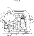
- the generator 10 includes an outer case 12 that forms an outer frame of the generator 10, an engine 15 that is housed in an inside 13 of the outer case 12, a power generating unit (a working unit) 16 that is provided at a front side of the engine 15, a cooling fan 17 that is provided at a front side of the power generating unit 16, and a recoil starter 18 that is provided at a front side of the cooling fan 17.
- an outer case 12 that forms an outer frame of the generator 10
- an engine 15 that is housed in an inside 13 of the outer case 12
- a power generating unit (a working unit) 16 that is provided at a front side of the engine
- a cooling fan 17 that is provided at a front side of the power generating unit 16
- a recoil starter 18 that is provided at a front side of the cooling fan 17.
- the generator 10 includes a carburetor 22 that connects to an intake port 21 of the engine 15, a muffler 24 that connects to an exhaust port 23 of the engine 15, a fuel tank 25 that is disposed in front of the engine 15, an inverter 27 that is provided under the fuel tank 25, an operation section 28 that is provided on a case front wall 12a of the outer case 12, an operation cover (cover) 29 that covers equipment 42 of the operation section 28, and outside air introduction means 30 that guides outside air to the inside 13 from an outside 14 of the outer case 12.
- a carburetor 22 that connects to an intake port 21 of the engine 15, a muffler 24 that connects to an exhaust port 23 of the engine 15, a fuel tank 25 that is disposed in front of the engine 15, an inverter 27 that is provided under the fuel tank 25, an operation section 28 that is provided on a case front wall 12a of the outer case 12, an operation cover (cover) 29 that covers equipment 42 of the operation section 28, and outside air introduction means 30 that guides outside air to the inside 13 from an outside 14 of the outer
- the engine 15, the power generating unit 16, the cooling fan 17, and the recoil starter 18 are housed in the inside 13 of the outer case 12. Further, the carburetor 22, the muffler 24, the fuel tank 25, the inverter 27 and the operation cover 29 are housed in the inside 13 of the outer case 12.
- the engine 15 drives by manually turning the recoil starter 18.
- the engine 15 drives, and thereby, a crankshaft 32 rotates.
- a rotor of the power generating unit 16 is connected to the crankshaft 32. Consequently, the rotor of the power generating unit 16 rotates by the crankshaft 32 rotating, and the power generating unit 16 drives.
- the power generating unit 16 drives, whereby an electromotive force is generated in the rotor and a stator, and power generation is performed in the power generating unit 16.
- Direct-current power that is generated in the power generating unit 16 is converted into alternating-current power in the inverter 27, and power is supplied to an outside from a connector 42a at the operation section 28.
- the cooling fan 17 is connected to the rotor of the power generating unit 16. Thereby, the cooling fan 17 rotates by the rotor of the power generating unit 16 rotating. The cooling fan 17 rotates, whereby outside air is sucked into the inside 13 from the outside 14 of the outer case 12 with the outside air introduction means 30.
- the sucked outside air is fed to the fuel tank 25, the inverter 27, the engine 15 and the muffler 24 in sequence as cooling air. Thereby, the fuel tank 25, the inverter 27, the engine 15 and the muffler 24 can be cooled with the cooling air.
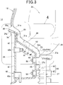
- a case concave portion 34 is formed in the case front wall 12a of the outer case 12, and the operation section 28 is mounted to the case concave portion 34. Further, an intake port 36 is formed in a site of an upper end portion 34a of the case concave portion 34, in the case front wall 12a at an upper side.
- the intake port 36 is disposed between the upper end portion 34a of the case concave portion 34 and a lower end 37a of a tank front wall (a wall portion) 37.
- the tank front wall 37 is a wall portion that forms a front wall of the fuel tank 25.
- the intake port 36 is formed in a lower side part 12b of the tank front wall 37, in the case front wall 12a.
- the intake port 36 is an opening that extends in a lateral direction along an upper side of the operation section 28 and is formed into a substantially rectangular shape, as one example.
- the operation section 28 is disposed under the intake port 36, and under a tank bottom portion 38 (described later) of the fuel tank 25.
- the operation section 28 includes an operation panel 41 that is mounted to the case concave portion 34, and the equipment 42 such as a connector 42a, and a switch (for example, an eco-throttle switch) 42b that are provided on the operation panel 41.
- the connector 42a By the connector 42a, the alternating-current power that is converted in the inverter 27 is guided to the outside.
- the operation cover 29 has a cover rear wall 45 that is disposed behind the operation panel 41, a cover top portion (a top portion) 46 that extends toward the operation panel 41 from an upper end 45a of the cover rear wall 45, a cover upper front portion 47 that is raised upward from an upper end 46a of the cover top portion 46, and a cover bottom portion 48 that extends toward the operation panel 41 from a lower end 45b of the cover rear wall 45.
- the cover top portion 46 is extended in an inclined shape with a rising gradient toward the upper end portion 41a of the operation panel 41 from the upper end 45a of the cover rear wall 45.
- a lower end portion 46b of the cover top portion 46 is disposed at a substantially same height as an upper end portion 27a of the inverter 27.
- the tank bottom portion (the bottom portion) 38 of the fuel tank 25 is disposed over the cover top portion 46 and the inverter 27.
- the tank bottom portion 38 has a first tank bend portion 51 that is disposed behind the upper edge 36a of the intake port 36, a tank inclined portion 52 that is disposed along the cover top portion 46 from a lower end 51a of the first tank bend portion 51, and a second tank bend portion (bend portion) 53 that is connected to a lower end 52a of the tank inclined portion 52.
- the first tank bend portion 51 is formed into a concave shape toward an upper rear side along the upper end portion 34a of the case concave portion 34 and the cover upper front portion 47. Further, the first tank bend portion 51 is disposed at an upper rear side along the upper end portion 34a of the case concave portion 34 and the cover upper front portion 47 with a space left from the upper end portion 34a and the cover upper front portion 47.
- the tank inclined portion 52 is integrally connected to the lower end 51a of the first tank bend portion 51.
- the tank inclined portion 52 is inclined with a falling gradient toward the upper end portion 27a of the inverter 27 from the lower end 51a of the first tank bend portion 51, and is disposed over the cover top portion 46 with a space left with respect to the cover top portion 46.
- the cover top portion 46 is disposed in an inclined shape with a space left with respect to the tank inclined portion 52.
- the second tank bend portion 53 is integrally connected to the lower end 52a of the tank inclined portion 52.
- the second tank bend portion 53 extends in a bent shape from the lower end 52a of the tank inclined portion 52 to an upper end 27c of a radiating surface 27b of the inverter 27. More specifically, the second tank bend portion 53 is formed into a bent shape to be recessed to an upper rear side along an intersection portion 49 of the cover top portion 46 and the cover rear wall 45, with a space left with respect to the intersection portion 49.
- the inverter 27 is provided under the second tank bend portion 53 and in front of (that is, at a suction side of the cooling fan 17) the cooling fan 17 (refer to FIG. 2 ).
- the inverter 27 is mounted to the cover rear wall 45 of the operation cover 29 with bolts 56. In this state, the radiating surface 27b of the inverter 27 is disposed in a state where the radiating surface 27b of the inverter 27 faces the cover rear wall 45, and is raised substantially vertically with a space left with respect to the cover rear wall 45.
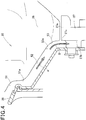
- the tank inclined portion 52 is inclined with a falling gradient toward the upper end portion 27a of the inverter 27 from the lower end 51a of the first tank bend portion 51. Consequently, cooling air is guided along the tank inclined portion 52 like an arrow A.
- the radiating surface 27b of the inverter 27 is disposed in a state where the radiating surface 27b is raised substantially vertically.
- the second tank bend portion 53 is formed on the tank bottom portion 38 of the fuel tank 25, and the second tank bend portion 53 is extended into a bent shape to the upper end 27c of the radiating surface 27b of the inverter 27 from the lower end 52a of the tank inclined portion 52.
- the cooling air that is guided along the tank inclined portion 52 can be smoothly guided to the radiating surface 27b of the inverter 27 with the second tank bend portion 53.
- the cooling air that is guided along the tank inclined portion 52 is smoothly (that is, efficiently) guided to the radiating surface 27b of the inverter 27 via the second tank bend portion 53 like an arrow B.
- the second bend portion 53 does not have to be formed by an exclusive member (that is, a shroud). Thereby, the number of components can be decreased.
- the outside air introduction means 30 includes the intake port 36 that is formed in the case front wall 12a of the outer case 12, a first air guide passage (an air guide passage) 61 that communicates with the intake port 36, and a second air guide passage 62 that communicates with the first air guide passage 61.
- the first air guide passage 61 has an upper passage wall 64 that is formed of the first tank bend portion 51, the tank inclined portion 52 and the second tank bend portion 53, and a lower passage wall 65 that is formed by the upper end portion 34a of the case concave portion 34, the cover upper front portion 47 and the cover top portion 46.
- a main part of the first air guide passage 61 is formed by the tank bottom portion 38 and the cover top portion 46. Further, a lower portion of the upper passage wall 64 is formed by the second tank bend portion 53.
- an upper end portion 61a of the first air guide passage 61 communicates with the intake port 36.
- the intake port 36 is opened to the outside 14 of the outer case 12. Consequently, outside air in the outside 14 of the outer case 12 is guided to the first air guide passage 61 through the intake port 36 as the cooling air.
- the upper passage wall 64 of the first air guide passage 61 is formed by the tank bottom portion 38.
- the tank bottom portion 38 (more specifically, the fuel in the fuel tank 25) can be favorably cooled with the cooling air that is guided to the first air guide passage 61.
- a lower end portion 53a of the second tank bend portion 53 is made adjacent to the upper end 27c of the radiating surface 27b of the inverter 27, and is disposed on a substantially same plane as the upper end 27c. Further, a lower end portion 61b of the first air guide passage 61 communicates with an upper end portion 62a of the second air guide passage 62.
- the cooling air that is guided to the first air guide passage 61 is efficiently guided to the radiating surface 27b of the inverter 27 and the upper end portion 62a of the second air guide passage 62 with the second tank bend portion 53.
- the second air guide passage 62 has a front passage wall 67 that is formed by the cover rear wall 45, and a rear passage wall 68 that is formed by the radiating surface 27b of the inverter 27. That is, the second air guide passage 62 that extends in the vertical direction is formed by the cover rear wall 45 and the radiating surface 27b of the inverter 27.
- a lower end portion 62b of the second air guide passage 62 communicates with a space 69 between a lower end 27d of the inverter 27 and the undercover 19, as illustrated in FIG. 2 .
- the cooling air that is guided to the upper end portion 62a of the second air guide passage 62 is efficiently guided to the lower end 27d (refer to FIG. 2 ) of the radiating surface 27b along the second air guide passage 62 (that is, the radiating surface 27b of the inverter 27).
- the radiating surface 27b (that is, the inverter 27) of the inverter 27 can be favorably cooled.
- the second tank bend portion 53 is included in a lower portion of the first air guide passage 61. Consequently, the cooling air can be guided to the radiating surface 27b of the inverter 27 with the second tank bend portion 53. Thereby, the cooling air can be efficiently guided to the radiating surface 27b of the inverter 27, and the inverter 27 can be cooled more favorably.
- the opening in the case front wall 12a can be reduced to be small, and noise of the generator 10 can be reduced.
- tank bottom portion 38, the cover top portion 46 and the like are also used as the members that form the first air guide passage 61.
- the radiating surface 27b of the inverter 27 and the cover rear wall 45 are also used as the members that form the second air guide passage 62.
- the engine 15 drives and the cooling fan 17 rotates.
- the cooling fan 17 rotates, whereby outside air of the outside 14 is guided to the first air guide passage 61 through the intake port 36 as the cooling air like an arrow C.
- the tank bottom portion 38 (more specifically, the fuel in the fuel tank 25) can be favorably cooled with the cooling air that is guided to the first air guide passage 61.
- the cooling air that is guided to the first air guide passage 61 is efficiently guided toward the radiating surface 27b of the inverter 27 and the upper end portion 62a of the second air guide passage 62 with the second tank bend portion 53.
- the cooling air that is guided is efficiently guided like an arrow D to the lower end 27d of the radiating surface 27b along the second air guide passage 62 (that is, the radiating surface 27b of the inverter 27).
- the radiating surface 27b (that is, the inverter 27) of the inverter 27 can be favorably cooled with the cooling air that is guided to the second air guide passage 62.
- both members of the fuel tank 25 and the inverter 27 can be cooled by only forming the single intake port 36 in the case front wall 12a.
- the cooling air that is guided to the lower end 27d of the radiating surface 27b is guided (sucked) like an arrow E toward the cooling fan 17 through the space 69.
- the cooling air that is sucked to the cooling fan 17 is sent like an arrow F toward the engine 15 from the cooling fan 17.
- the power generating unit 16 can be cooled with the cooling air that is sent.
- the cooling air that cools the power generating unit 16 is guided like an arrow G along the engine 15.
- the engine 15 can be cooled with the cooling air that is guided.
- the muffler 24 is cooled with the cooling air that cools the engine 15.
- the cooling air that cools the muffler 24 is discharged to the outside 14 from a louver 71 of the outer case 12.
- engine-driven working machine is not limited to the aforementioned embodiment, and can be properly modified, and altered.
- the present invention is not limited to this. It is also possible to form the first air guide passage 61 by only the tank bottom portion 38 of the fuel tank 25, for example.
- the fuel tank 25 can be also favorably cooled with the cooling air, and the inverter 27 can be also further cooled favorably, as in the embodiment.
- the present invention is not limited to this. It is also possible to form the second air guide passage 62 by only the radiating surface 27b of the inverter 27, for example.
- the inverter 27 can be also favorably cooled, as in the embodiment.
- the shapes and the configurations of the generator, the outer case, cooling fan, the fuel tank, the inverter, the operation section, the operation cover, the intake port, the tank front wall, the tank bottom portion, the equipment, the cover top portion, the second tank bend portion, the first air guide passage and the like are not limited to the shapes and the configurations that are illustrated, but can be properly changed.
- the present invention is suitable for application to the engine-driven working machine in which the cooling fan and the inverter are provided in the inside of the outer case, and the fuel tank is provided over the inverter.
- An engine-driven working machine 10 capable of reducing an opening of an outer case to be small, and decreasing the number of components is provided.
- An engine-driven working machine 10 is a generator in which an inverter 27 is provided at a suction side of a cooling fan 17, and a fuel tank 25 is provided over the inverter 27.
- the generator 10 includes an intake port 36 that is formed in an outer case 12, and a first air guide passage 61 that is formed by a tank bottom portion 38 of the fuel tank 25.
- the intake port 36 is formed in a lower side part 12b of a tank front wall 37, in the outer case 12.
- the first air guide passage 61 is formed by the tank bottom portion 38 that is inclined with a falling gradient toward the inverter 27 from the intake port 36.
Landscapes
- Engineering & Computer Science (AREA)
- Chemical & Material Sciences (AREA)
- Combustion & Propulsion (AREA)
- Mechanical Engineering (AREA)
- General Engineering & Computer Science (AREA)
- Power Engineering (AREA)
- Cooling, Air Intake And Gas Exhaust, And Fuel Tank Arrangements In Propulsion Units (AREA)
- Motor Or Generator Cooling System (AREA)
- Inverter Devices (AREA)
Applications Claiming Priority (1)
| Application Number | Priority Date | Filing Date | Title |
|---|---|---|---|
| JP2016051635A JP6628651B2 (ja) | 2016-03-15 | 2016-03-15 | エンジン駆動作業機 |
Publications (2)
| Publication Number | Publication Date |
|---|---|
| EP3219951A1 true EP3219951A1 (fr) | 2017-09-20 |
| EP3219951B1 EP3219951B1 (fr) | 2019-03-27 |
Family
ID=57914743
Family Applications (1)
| Application Number | Title | Priority Date | Filing Date |
|---|---|---|---|
| EP17152867.2A Active EP3219951B1 (fr) | 2016-03-15 | 2017-01-24 | Machine de travail motorisée |
Country Status (4)
| Country | Link |
|---|---|
| US (1) | US10122245B2 (fr) |
| EP (1) | EP3219951B1 (fr) |
| JP (1) | JP6628651B2 (fr) |
| CN (1) | CN107191259B (fr) |
Cited By (2)
| Publication number | Priority date | Publication date | Assignee | Title |
|---|---|---|---|---|
| US20220352783A1 (en) * | 2020-12-18 | 2022-11-03 | N.P.S. Company, LLC | Air-cooling system for portable generator |
| WO2026052596A1 (fr) * | 2024-09-03 | 2026-03-12 | Vincorion Power Systems Gmbh | Dispositif de fourniture d'énergie électrique |
Families Citing this family (8)
| Publication number | Priority date | Publication date | Assignee | Title |
|---|---|---|---|---|
| JP6687433B2 (ja) * | 2016-03-16 | 2020-04-22 | 本田技研工業株式会社 | エンジン駆動作業機 |
| CN111075549B (zh) * | 2018-08-30 | 2022-02-08 | 本田技研工业株式会社 | 通用发动机 |
| CN109639029A (zh) * | 2018-12-27 | 2019-04-16 | 重庆宗申通用动力机械有限公司 | 一种手提式变频发电机 |
| JP2020108318A (ja) * | 2018-12-28 | 2020-07-09 | 本田技研工業株式会社 | 発電装置 |
| CN113302388B (zh) * | 2019-01-21 | 2023-01-13 | 本田技研工业株式会社 | 发电装置 |
| JP2021087239A (ja) * | 2019-11-25 | 2021-06-03 | 本田技研工業株式会社 | 発電機 |
| WO2023053196A1 (fr) * | 2021-09-28 | 2023-04-06 | 本田技研工業株式会社 | Générateur |
| CN113982734B (zh) * | 2021-11-11 | 2023-03-21 | 中国科学院江西稀土研究院 | 一种汽油发电机组的风冷散热装置及其方法 |
Citations (4)
| Publication number | Priority date | Publication date | Assignee | Title |
|---|---|---|---|---|
| JPH11200876A (ja) * | 1998-01-19 | 1999-07-27 | Honda Motor Co Ltd | 携帯用エンジン作業機 |
| EP1069293A2 (fr) * | 1999-07-12 | 2001-01-17 | Honda Giken Kogyo Kabushiki Kaisha | Dispositif entraíné par un moteur à combustion interne |
| JP2001027125A (ja) * | 1999-07-12 | 2001-01-30 | Honda Motor Co Ltd | エンジン発電機 |
| WO2008032414A1 (fr) | 2006-09-14 | 2008-03-20 | Shindaiwa Corporation | Générateur de moteur insonore |
Family Cites Families (7)
| Publication number | Priority date | Publication date | Assignee | Title |
|---|---|---|---|---|
| JPS60145415A (ja) * | 1984-11-29 | 1985-07-31 | Kawasaki Heavy Ind Ltd | 小形発電装置 |
| US4647835A (en) * | 1984-12-19 | 1987-03-03 | Kawasaki Jukogyo Kabushiki Kaisha | Portable generator |
| JPH04117142U (ja) * | 1991-03-29 | 1992-10-20 | 株式会社クボタ | 燃料タンク頭載形強制空冷エンジンの燃料タンク防熱装置 |
| JP3696441B2 (ja) * | 1999-07-12 | 2005-09-21 | 本田技研工業株式会社 | エンジン発電機 |
| JP2008014164A (ja) * | 2006-07-03 | 2008-01-24 | Yanmar Co Ltd | エンジン発電機 |
| JP2010007582A (ja) * | 2008-06-27 | 2010-01-14 | Honda Motor Co Ltd | エンジン駆動発電機 |
| JP4997190B2 (ja) * | 2008-06-27 | 2012-08-08 | 本田技研工業株式会社 | エンジン駆動発電機 |
-
2016
- 2016-03-15 JP JP2016051635A patent/JP6628651B2/ja not_active Expired - Fee Related
-
2017
- 2017-01-24 EP EP17152867.2A patent/EP3219951B1/fr active Active
- 2017-02-24 CN CN201710106003.7A patent/CN107191259B/zh not_active Expired - Fee Related
- 2017-03-09 US US15/454,482 patent/US10122245B2/en active Active
Patent Citations (4)
| Publication number | Priority date | Publication date | Assignee | Title |
|---|---|---|---|---|
| JPH11200876A (ja) * | 1998-01-19 | 1999-07-27 | Honda Motor Co Ltd | 携帯用エンジン作業機 |
| EP1069293A2 (fr) * | 1999-07-12 | 2001-01-17 | Honda Giken Kogyo Kabushiki Kaisha | Dispositif entraíné par un moteur à combustion interne |
| JP2001027125A (ja) * | 1999-07-12 | 2001-01-30 | Honda Motor Co Ltd | エンジン発電機 |
| WO2008032414A1 (fr) | 2006-09-14 | 2008-03-20 | Shindaiwa Corporation | Générateur de moteur insonore |
Cited By (6)
| Publication number | Priority date | Publication date | Assignee | Title |
|---|---|---|---|---|
| US20220352783A1 (en) * | 2020-12-18 | 2022-11-03 | N.P.S. Company, LLC | Air-cooling system for portable generator |
| US11646627B2 (en) * | 2020-12-18 | 2023-05-09 | N.P.S. Company, LLC | Air-cooling system for portable generator |
| US11955868B2 (en) | 2020-12-18 | 2024-04-09 | N.P.S. Company, LLC | Air-cooling system for portable generator |
| US11979076B2 (en) | 2020-12-18 | 2024-05-07 | N.P.S. Company, LLC | Air-cooling system for portable generator |
| US12368341B2 (en) | 2020-12-18 | 2025-07-22 | N.P.S. Company, LLC | Air-cooling system for portable generator |
| WO2026052596A1 (fr) * | 2024-09-03 | 2026-03-12 | Vincorion Power Systems Gmbh | Dispositif de fourniture d'énergie électrique |
Also Published As
| Publication number | Publication date |
|---|---|
| US20170271953A1 (en) | 2017-09-21 |
| US10122245B2 (en) | 2018-11-06 |
| CN107191259B (zh) | 2019-09-13 |
| CN107191259A (zh) | 2017-09-22 |
| JP2017166396A (ja) | 2017-09-21 |
| EP3219951B1 (fr) | 2019-03-27 |
| JP6628651B2 (ja) | 2020-01-15 |
Similar Documents
| Publication | Publication Date | Title |
|---|---|---|
| EP3219951B1 (fr) | Machine de travail motorisée | |
| US10273864B2 (en) | Engine-driven generator | |
| EP2739835B1 (fr) | Configuration de ventilateur pour un générateur commandé par un moteur | |
| CN107201948B (zh) | 发动机驱动作业机 | |
| US8210133B2 (en) | Engine-driven power generator apparatus | |
| CN106014587B (zh) | 发动机驱动式发电机 | |
| CN103256116B (zh) | 发动机驱动型发电机设备 | |
| CN107201941B (zh) | 发动机驱动作业机 | |
| US5626105A (en) | Vertical shaft generator with single cooling fan | |
| US20090320773A1 (en) | Engine generator | |
| CN103075237B (zh) | 发动机作业机 | |
| CN108290492B (zh) | 内燃机的冷却设备和包括该冷却设备的机动车辆 | |
| EP2587068B1 (fr) | Ensemble de conduit de ventilateur de refroidissement | |
| JP5996480B2 (ja) | 作業機用空冷エンジン | |
| JP4909319B2 (ja) | エンジン駆動発電機 | |
| US10001055B2 (en) | Engine-driven working machine housed in outer case with vibration isolating support | |
| JP2010007599A (ja) | エンジン駆動発電機 | |
| CN102352793A (zh) | 发动机驱动式发电机 | |
| JP4399329B2 (ja) | エンジン | |
| US7406958B2 (en) | Snow remover | |
| CN105940215B (zh) | 便携用作业机械 |
Legal Events
| Date | Code | Title | Description |
|---|---|---|---|
| PUAI | Public reference made under article 153(3) epc to a published international application that has entered the european phase |
Free format text: ORIGINAL CODE: 0009012 |
|
| STAA | Information on the status of an ep patent application or granted ep patent |
Free format text: STATUS: REQUEST FOR EXAMINATION WAS MADE |
|
| 17P | Request for examination filed |
Effective date: 20170124 |
|
| AK | Designated contracting states |
Kind code of ref document: A1 Designated state(s): AL AT BE BG CH CY CZ DE DK EE ES FI FR GB GR HR HU IE IS IT LI LT LU LV MC MK MT NL NO PL PT RO RS SE SI SK SM TR |
|
| AX | Request for extension of the european patent |
Extension state: BA ME |
|
| STAA | Information on the status of an ep patent application or granted ep patent |
Free format text: STATUS: EXAMINATION IS IN PROGRESS |
|
| 17Q | First examination report despatched |
Effective date: 20180612 |
|
| GRAP | Despatch of communication of intention to grant a patent |
Free format text: ORIGINAL CODE: EPIDOSNIGR1 |
|
| STAA | Information on the status of an ep patent application or granted ep patent |
Free format text: STATUS: GRANT OF PATENT IS INTENDED |
|
| INTG | Intention to grant announced |
Effective date: 20181123 |
|
| GRAS | Grant fee paid |
Free format text: ORIGINAL CODE: EPIDOSNIGR3 |
|
| GRAA | (expected) grant |
Free format text: ORIGINAL CODE: 0009210 |
|
| STAA | Information on the status of an ep patent application or granted ep patent |
Free format text: STATUS: THE PATENT HAS BEEN GRANTED |
|
| AK | Designated contracting states |
Kind code of ref document: B1 Designated state(s): AL AT BE BG CH CY CZ DE DK EE ES FI FR GB GR HR HU IE IS IT LI LT LU LV MC MK MT NL NO PL PT RO RS SE SI SK SM TR |
|
| REG | Reference to a national code |
Ref country code: GB Ref legal event code: FG4D |
|
| REG | Reference to a national code |
Ref country code: CH Ref legal event code: EP |
|
| REG | Reference to a national code |
Ref country code: AT Ref legal event code: REF Ref document number: 1113363 Country of ref document: AT Kind code of ref document: T Effective date: 20190415 |
|
| REG | Reference to a national code |
Ref country code: IE Ref legal event code: FG4D |
|
| REG | Reference to a national code |
Ref country code: DE Ref legal event code: R096 Ref document number: 602017002851 Country of ref document: DE |
|
| PG25 | Lapsed in a contracting state [announced via postgrant information from national office to epo] |
Ref country code: FI Free format text: LAPSE BECAUSE OF FAILURE TO SUBMIT A TRANSLATION OF THE DESCRIPTION OR TO PAY THE FEE WITHIN THE PRESCRIBED TIME-LIMIT Effective date: 20190327 Ref country code: SE Free format text: LAPSE BECAUSE OF FAILURE TO SUBMIT A TRANSLATION OF THE DESCRIPTION OR TO PAY THE FEE WITHIN THE PRESCRIBED TIME-LIMIT Effective date: 20190327 Ref country code: NO Free format text: LAPSE BECAUSE OF FAILURE TO SUBMIT A TRANSLATION OF THE DESCRIPTION OR TO PAY THE FEE WITHIN THE PRESCRIBED TIME-LIMIT Effective date: 20190627 Ref country code: LT Free format text: LAPSE BECAUSE OF FAILURE TO SUBMIT A TRANSLATION OF THE DESCRIPTION OR TO PAY THE FEE WITHIN THE PRESCRIBED TIME-LIMIT Effective date: 20190327 |
|
| REG | Reference to a national code |
Ref country code: NL Ref legal event code: MP Effective date: 20190327 |
|
| PG25 | Lapsed in a contracting state [announced via postgrant information from national office to epo] |
Ref country code: NL Free format text: LAPSE BECAUSE OF FAILURE TO SUBMIT A TRANSLATION OF THE DESCRIPTION OR TO PAY THE FEE WITHIN THE PRESCRIBED TIME-LIMIT Effective date: 20190327 Ref country code: RS Free format text: LAPSE BECAUSE OF FAILURE TO SUBMIT A TRANSLATION OF THE DESCRIPTION OR TO PAY THE FEE WITHIN THE PRESCRIBED TIME-LIMIT Effective date: 20190327 Ref country code: BG Free format text: LAPSE BECAUSE OF FAILURE TO SUBMIT A TRANSLATION OF THE DESCRIPTION OR TO PAY THE FEE WITHIN THE PRESCRIBED TIME-LIMIT Effective date: 20190627 Ref country code: LV Free format text: LAPSE BECAUSE OF FAILURE TO SUBMIT A TRANSLATION OF THE DESCRIPTION OR TO PAY THE FEE WITHIN THE PRESCRIBED TIME-LIMIT Effective date: 20190327 Ref country code: GR Free format text: LAPSE BECAUSE OF FAILURE TO SUBMIT A TRANSLATION OF THE DESCRIPTION OR TO PAY THE FEE WITHIN THE PRESCRIBED TIME-LIMIT Effective date: 20190628 Ref country code: HR Free format text: LAPSE BECAUSE OF FAILURE TO SUBMIT A TRANSLATION OF THE DESCRIPTION OR TO PAY THE FEE WITHIN THE PRESCRIBED TIME-LIMIT Effective date: 20190327 |
|
| REG | Reference to a national code |
Ref country code: AT Ref legal event code: MK05 Ref document number: 1113363 Country of ref document: AT Kind code of ref document: T Effective date: 20190327 |
|
| PG25 | Lapsed in a contracting state [announced via postgrant information from national office to epo] |
Ref country code: EE Free format text: LAPSE BECAUSE OF FAILURE TO SUBMIT A TRANSLATION OF THE DESCRIPTION OR TO PAY THE FEE WITHIN THE PRESCRIBED TIME-LIMIT Effective date: 20190327 Ref country code: ES Free format text: LAPSE BECAUSE OF FAILURE TO SUBMIT A TRANSLATION OF THE DESCRIPTION OR TO PAY THE FEE WITHIN THE PRESCRIBED TIME-LIMIT Effective date: 20190327 Ref country code: AL Free format text: LAPSE BECAUSE OF FAILURE TO SUBMIT A TRANSLATION OF THE DESCRIPTION OR TO PAY THE FEE WITHIN THE PRESCRIBED TIME-LIMIT Effective date: 20190327 Ref country code: PT Free format text: LAPSE BECAUSE OF FAILURE TO SUBMIT A TRANSLATION OF THE DESCRIPTION OR TO PAY THE FEE WITHIN THE PRESCRIBED TIME-LIMIT Effective date: 20190727 Ref country code: CZ Free format text: LAPSE BECAUSE OF FAILURE TO SUBMIT A TRANSLATION OF THE DESCRIPTION OR TO PAY THE FEE WITHIN THE PRESCRIBED TIME-LIMIT Effective date: 20190327 Ref country code: RO Free format text: LAPSE BECAUSE OF FAILURE TO SUBMIT A TRANSLATION OF THE DESCRIPTION OR TO PAY THE FEE WITHIN THE PRESCRIBED TIME-LIMIT Effective date: 20190327 Ref country code: SK Free format text: LAPSE BECAUSE OF FAILURE TO SUBMIT A TRANSLATION OF THE DESCRIPTION OR TO PAY THE FEE WITHIN THE PRESCRIBED TIME-LIMIT Effective date: 20190327 |
|
| PG25 | Lapsed in a contracting state [announced via postgrant information from national office to epo] |
Ref country code: PL Free format text: LAPSE BECAUSE OF FAILURE TO SUBMIT A TRANSLATION OF THE DESCRIPTION OR TO PAY THE FEE WITHIN THE PRESCRIBED TIME-LIMIT Effective date: 20190327 Ref country code: SM Free format text: LAPSE BECAUSE OF FAILURE TO SUBMIT A TRANSLATION OF THE DESCRIPTION OR TO PAY THE FEE WITHIN THE PRESCRIBED TIME-LIMIT Effective date: 20190327 |
|
| PG25 | Lapsed in a contracting state [announced via postgrant information from national office to epo] |
Ref country code: AT Free format text: LAPSE BECAUSE OF FAILURE TO SUBMIT A TRANSLATION OF THE DESCRIPTION OR TO PAY THE FEE WITHIN THE PRESCRIBED TIME-LIMIT Effective date: 20190327 Ref country code: IS Free format text: LAPSE BECAUSE OF FAILURE TO SUBMIT A TRANSLATION OF THE DESCRIPTION OR TO PAY THE FEE WITHIN THE PRESCRIBED TIME-LIMIT Effective date: 20190727 |
|
| REG | Reference to a national code |
Ref country code: DE Ref legal event code: R097 Ref document number: 602017002851 Country of ref document: DE |
|
| PG25 | Lapsed in a contracting state [announced via postgrant information from national office to epo] |
Ref country code: DK Free format text: LAPSE BECAUSE OF FAILURE TO SUBMIT A TRANSLATION OF THE DESCRIPTION OR TO PAY THE FEE WITHIN THE PRESCRIBED TIME-LIMIT Effective date: 20190327 |
|
| PLBE | No opposition filed within time limit |
Free format text: ORIGINAL CODE: 0009261 |
|
| STAA | Information on the status of an ep patent application or granted ep patent |
Free format text: STATUS: NO OPPOSITION FILED WITHIN TIME LIMIT |
|
| PG25 | Lapsed in a contracting state [announced via postgrant information from national office to epo] |
Ref country code: SI Free format text: LAPSE BECAUSE OF FAILURE TO SUBMIT A TRANSLATION OF THE DESCRIPTION OR TO PAY THE FEE WITHIN THE PRESCRIBED TIME-LIMIT Effective date: 20190327 |
|
| 26N | No opposition filed |
Effective date: 20200103 |
|
| PG25 | Lapsed in a contracting state [announced via postgrant information from national office to epo] |
Ref country code: TR Free format text: LAPSE BECAUSE OF FAILURE TO SUBMIT A TRANSLATION OF THE DESCRIPTION OR TO PAY THE FEE WITHIN THE PRESCRIBED TIME-LIMIT Effective date: 20190327 |
|
| PGFP | Annual fee paid to national office [announced via postgrant information from national office to epo] |
Ref country code: IT Payment date: 20200131 Year of fee payment: 4 |
|
| PG25 | Lapsed in a contracting state [announced via postgrant information from national office to epo] |
Ref country code: MC Free format text: LAPSE BECAUSE OF FAILURE TO SUBMIT A TRANSLATION OF THE DESCRIPTION OR TO PAY THE FEE WITHIN THE PRESCRIBED TIME-LIMIT Effective date: 20190327 |
|
| REG | Reference to a national code |
Ref country code: CH Ref legal event code: PL |
|
| REG | Reference to a national code |
Ref country code: BE Ref legal event code: MM Effective date: 20200131 |
|
| PG25 | Lapsed in a contracting state [announced via postgrant information from national office to epo] |
Ref country code: LU Free format text: LAPSE BECAUSE OF NON-PAYMENT OF DUE FEES Effective date: 20200124 |
|
| PG25 | Lapsed in a contracting state [announced via postgrant information from national office to epo] |
Ref country code: CH Free format text: LAPSE BECAUSE OF NON-PAYMENT OF DUE FEES Effective date: 20200131 Ref country code: LI Free format text: LAPSE BECAUSE OF NON-PAYMENT OF DUE FEES Effective date: 20200131 Ref country code: BE Free format text: LAPSE BECAUSE OF NON-PAYMENT OF DUE FEES Effective date: 20200131 |
|
| PG25 | Lapsed in a contracting state [announced via postgrant information from national office to epo] |
Ref country code: IE Free format text: LAPSE BECAUSE OF NON-PAYMENT OF DUE FEES Effective date: 20200124 |
|
| GBPC | Gb: european patent ceased through non-payment of renewal fee |
Effective date: 20210124 |
|
| PG25 | Lapsed in a contracting state [announced via postgrant information from national office to epo] |
Ref country code: GB Free format text: LAPSE BECAUSE OF NON-PAYMENT OF DUE FEES Effective date: 20210124 |
|
| PG25 | Lapsed in a contracting state [announced via postgrant information from national office to epo] |
Ref country code: IT Free format text: LAPSE BECAUSE OF NON-PAYMENT OF DUE FEES Effective date: 20210124 |
|
| PG25 | Lapsed in a contracting state [announced via postgrant information from national office to epo] |
Ref country code: MT Free format text: LAPSE BECAUSE OF FAILURE TO SUBMIT A TRANSLATION OF THE DESCRIPTION OR TO PAY THE FEE WITHIN THE PRESCRIBED TIME-LIMIT Effective date: 20190327 Ref country code: CY Free format text: LAPSE BECAUSE OF FAILURE TO SUBMIT A TRANSLATION OF THE DESCRIPTION OR TO PAY THE FEE WITHIN THE PRESCRIBED TIME-LIMIT Effective date: 20190327 |
|
| PG25 | Lapsed in a contracting state [announced via postgrant information from national office to epo] |
Ref country code: MK Free format text: LAPSE BECAUSE OF FAILURE TO SUBMIT A TRANSLATION OF THE DESCRIPTION OR TO PAY THE FEE WITHIN THE PRESCRIBED TIME-LIMIT Effective date: 20190327 |
|
| REG | Reference to a national code |
Ref country code: DE Ref legal event code: R084 Ref document number: 602017002851 Country of ref document: DE |
|
| PGFP | Annual fee paid to national office [announced via postgrant information from national office to epo] |
Ref country code: FR Payment date: 20221208 Year of fee payment: 7 |
|
| PGFP | Annual fee paid to national office [announced via postgrant information from national office to epo] |
Ref country code: DE Payment date: 20221130 Year of fee payment: 7 |
|
| REG | Reference to a national code |
Ref country code: DE Ref legal event code: R119 Ref document number: 602017002851 Country of ref document: DE |
|
| PG25 | Lapsed in a contracting state [announced via postgrant information from national office to epo] |
Ref country code: DE Free format text: LAPSE BECAUSE OF NON-PAYMENT OF DUE FEES Effective date: 20240801 |
|
| PG25 | Lapsed in a contracting state [announced via postgrant information from national office to epo] |
Ref country code: FR Free format text: LAPSE BECAUSE OF NON-PAYMENT OF DUE FEES Effective date: 20240131 |
|
| PG25 | Lapsed in a contracting state [announced via postgrant information from national office to epo] |
Ref country code: FR Free format text: LAPSE BECAUSE OF NON-PAYMENT OF DUE FEES Effective date: 20240131 Ref country code: DE Free format text: LAPSE BECAUSE OF NON-PAYMENT OF DUE FEES Effective date: 20240801 |