EP3220107A1 - Messvorrichtung mit einem durchflussmessgerät und verfahren zum betreiben einer messvorrichtung - Google Patents
Messvorrichtung mit einem durchflussmessgerät und verfahren zum betreiben einer messvorrichtung Download PDFInfo
- Publication number
- EP3220107A1 EP3220107A1 EP17159164.7A EP17159164A EP3220107A1 EP 3220107 A1 EP3220107 A1 EP 3220107A1 EP 17159164 A EP17159164 A EP 17159164A EP 3220107 A1 EP3220107 A1 EP 3220107A1
- Authority
- EP
- European Patent Office
- Prior art keywords
- medium
- tube
- pipe
- segment
- measuring
- Prior art date
- Legal status (The legal status is an assumption and is not a legal conclusion. Google has not performed a legal analysis and makes no representation as to the accuracy of the status listed.)
- Granted
Links
Images

Classifications
-
- G—PHYSICS
- G01—MEASURING; TESTING
- G01F—MEASURING VOLUME, VOLUME FLOW, MASS FLOW OR LIQUID LEVEL; METERING BY VOLUME
- G01F15/00—Details of, or accessories for, apparatus of groups G01F1/00 - G01F13/00 insofar as such details or appliances are not adapted to particular types of such apparatus
- G01F15/005—Valves
-
- G—PHYSICS
- G01—MEASURING; TESTING
- G01F—MEASURING VOLUME, VOLUME FLOW, MASS FLOW OR LIQUID LEVEL; METERING BY VOLUME
- G01F1/00—Measuring the volume flow or mass flow of fluid or fluent solid material wherein the fluid passes through a meter in a continuous flow
- G01F1/74—Devices for measuring flow of a fluid or flow of a fluent solid material in suspension in another fluid
-
- G—PHYSICS
- G01—MEASURING; TESTING
- G01F—MEASURING VOLUME, VOLUME FLOW, MASS FLOW OR LIQUID LEVEL; METERING BY VOLUME
- G01F1/00—Measuring the volume flow or mass flow of fluid or fluent solid material wherein the fluid passes through a meter in a continuous flow
- G01F1/704—Measuring the volume flow or mass flow of fluid or fluent solid material wherein the fluid passes through a meter in a continuous flow using marked regions or existing inhomogeneities within the fluid stream, e.g. statistically occurring variations in a fluid parameter
- G01F1/708—Measuring the time taken to traverse a fixed distance
- G01F1/716—Measuring the time taken to traverse a fixed distance using electron paramagnetic resonance [EPR] or nuclear magnetic resonance [NMR]
-
- G—PHYSICS
- G01—MEASURING; TESTING
- G01F—MEASURING VOLUME, VOLUME FLOW, MASS FLOW OR LIQUID LEVEL; METERING BY VOLUME
- G01F15/00—Details of, or accessories for, apparatus of groups G01F1/00 - G01F13/00 insofar as such details or appliances are not adapted to particular types of such apparatus
- G01F15/18—Supports or connecting means for meters
- G01F15/185—Connecting means, e.g. bypass conduits
Definitions
- the invention relates firstly to a measuring device with a flow meter, an inlet pipe and an outlet pipe, wherein the flow meter has a measuring tube and the measuring tube is connected to the inlet pipe and the outlet pipe. Moreover, the invention also relates to a method for operating a measuring device.
- a flow meter with a measuring tube measures the flow of a medium through the measuring tube.
- the medium can be either a single-phase or a multi-phase medium.
- a single-phase medium comprises a single phase and a multi-phase medium comprises several phases.
- a medium may also comprise solid components.
- the flow of a phase through a meter tube refers to either a volume flow or a mass flow of the phase.
- mass flow can be calculated from the volume flow using the density of the phase. Accordingly, if a flowmeter directly measures a mass flow of a phase, mass flow using the density of the phase may determine the volume flow of the phase.
- both the inlet pipe and the outlet pipe are connected to the measuring tube such that a flowing medium first flows through the inlet pipe, then through the measuring pipe and finally through the outlet pipe.
- the medium flows directly from the inlet pipe into the measuring tube and directly from the measuring tube into the outlet pipe.
- the determination of the flow of a medium through a measuring tube requires the knowledge of certain properties of the medium. If the medium has, for example, several phases, individualizing properties of the individual phases must be known, which make the individual phases distinguishable for a flowmeter so that the flowmeter can determine the proportions of the individual phases on the medium and the throughputs of the individual phases. The properties are often dependent on the pressure and / or the temperature of the medium, which is why these Characteristics at the location of a flowmeter and can not be determined elsewhere during a calibration. The determination of these properties can be done, for example, by measurements of a flow meter on the stationary medium in the measuring tube. This applies in particular to the liquid components of the medium.
- An object of the present invention is therefore to provide a measuring device, the measurements of a flow meter in particular on the liquid components of a medium in the measuring tube regardless of whether the medium flows or stands still, the measuring tube completely with at least medium with at least the liquid components of the medium is filled.
- the inlet pipe, the measuring tube and the outlet pipe form a siphon.
- the siphon is designed and aligned with respect to the earth gravity vector, that when first a medium flows through the siphon and then stops the flow of the medium, the measuring tube is completely filled with the stationary medium, at least with the liquid components of the medium. The flow of the medium then stops in the siphon when the cause of the flow in the siphon ceases.
- the measuring device allows the flowmeter to perform measurements on the medium which is stationary in the measuring tube.
- the measurements are usually carried out at the temperature and / or pressure of the medium at the location of the flowmeter.
- the fact that measurements are usually carried out at the temperature of the medium at the operating location of the flowmeter is ensured by the fact that the measurements are carried out in time immediately after the flow of medium through the measuring tube ceases.
- the flow meter is a nuclear magnetic flow meter.
- a nuclear magnetic flowmeter uses nuclear magnetic resonance measurement techniques for analyzing and, in particular, measuring the flow of a medium through the measuring tube. Nuclear magnetic resonance measurements influence the precession of atomic nuclei of a medium in the presence of a macroscopic magnetic field by excitation of the atomic nuclei by means of a controlled magnetic field and evaluate the effect of the excitation on the atomic nuclei.
- a nuclear magnetic flowmeter therefore has a magnetizing device for generating a magnetic field in a medium flowing through the measuring tube and for exciting the medium in the measuring tube and for measuring the effect of the excitation on the medium in the measuring tube a measuring device.
- the atomic nuclei of elements possessing a nuclear spin also possess a magnetic moment caused by the nuclear spin.
- the nuclear spin can be thought of as an angular momentum writable by a vector and, correspondingly, the magnetic moment can also be described by a vector that is parallel to the vector of the angular momentum.
- the vector of the magnetic moment of an atomic nucleus in the presence of a macroscopic magnetic field, such as that generated by the magnetization device is oriented parallel to the vector of the macroscopic magnetic field at the location of the atomic nucleus.
- the vector of the magnetic moment of the atomic nucleus precesses around the vector of the macroscopic magnetic field at the point of the atomic nucleus.
- the frequency of the precession is referred to as the lobe frequency ⁇ L and is proportional to the magnitude of the magnetic field strength B.
- the properties can be determined, for example, by measurements of the nuclear magnetic flowmeter on the medium standing still in the measuring tube.
- the flow measurement may include the flow rates of the individual phases of the medium and the relative proportions of the individual phases on the multiphase medium.
- nuclear magnetic flowmeters can be used to analyze the multiphase medium extracted from oil wells. This medium consists essentially of the phases petroleum, natural gas and salt water, all phases containing hydrogen nuclei.
- the flowmeter performs measurements on the medium standing still in the measuring tube immediately after the flow of the medium has ceased. This ensures that the measurements are not affected by the fact that the individual phases separate on a multiphase medium and influence the measurements.
- the measuring tube is straight, has a measuring tube longitudinal axis and the measuring tube longitudinal axis is aligned perpendicular to Erdheefeldvektor.
- the inlet pipe and the outlet pipe each have a first pipe segment with a first pipe segment longitudinal axis, a second pipe segment with a second pipe segment longitudinal axis and a third pipe segment.
- first tube segment is connected to the measuring tube
- first tube segment and the second tube segment are interconnected by the third tube segment and are the first tube segment longitudinal axis and the second tube segment longitudinal axis spaced at a tube segment spacing and parallel to each other aligned.
- the tube segment spacing is selected such that when the medium is stationary, the measuring tube is completely filled at least with the liquid constituents of the medium.
- the pipe segment spacing is determined taking into account an assumed maximum flow rate and assumed properties of a medium that when the medium first flows through the inlet pipe, the measuring tube and the outlet pipe with the assumed maximum flow rate and then the cause for the flow of the medium ceases, the measuring tube is completely filled with the stationary medium.
- One of the assumed properties of the medium is, for example, the density of the medium.
- the inertia of the flowing medium can be determined. It is advantageous if at least the third pipe segment of the outlet pipe is arranged obliquely so that it forms a ramp in the opposite direction to the earth's gravity field vector for the flowing medium, so that the medium is braked.
- the inlet pipe and the outlet pipe each have a first pipe segment, a second pipe segment and a third pipe segment.
- the first tube segment is connected to the measuring tube
- the first tube segment and the second tube segment are interconnected by the third tube segment and have a projection of a first inner tube cross-sectional area of the first tube segment on a projection plane and a projection of a second inner tube cross-sectional area of the second tube segment on the projection level none Cut surface in the projection plane.
- the projection of the first pipe inner cross-sectional area and the projection of the second pipe inner cross-sectional area on the projection plane are separate. This ensures that a medium the measuring tube after ceasing the cause of the Flow of the medium also completely fills and does not flow through the inlet pipe or the outlet pipe from the measuring tube.
- a valve in each case, is made in each case for a valve to be arranged both in the inlet pipe and in the outlet pipe, or a valve is arranged either in the inlet pipe or in the outlet pipe in order to control the flow of a medium through the measuring pipe.
- the valve or the valves are designed to influence the flow of a medium through the measuring tube in such a way that the medium flows through the measuring tube or that a flow of the medium in the measuring tube ceases. The valve or valves are thus the cause when the flow of the medium stops.
- the measuring device whose inlet pipe and outlet pipe each have a first pipe segment, a second pipe segment and a third pipe segment, wherein the first pipe segment is connected to the measuring tube and the first pipe segment and the second pipe segment are interconnected by the third pipe segment , It is provided that the valve in the inlet pipe and the valve are arranged in the outlet pipe in each third pipe segment or that the valve in the inlet pipe or the valve is arranged in the outlet pipe in the corresponding third pipe segment.
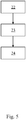
- the medium is not flowed through the inlet pipe, the measuring tube and the outlet pipe and are carried out by the flowmeter on the stationary in the measuring tube medium measurements.
- These measurements are for example Measurements for determining said individualizing properties of the individual phases of the multiphase medium, which make the individual phases distinguishable for the flowmeter, so that the flowmeter can determine the proportions of the individual phases on the medium and the flow rates of the individual phases.
- the accuracy of the measurements from the first method step is increased using the measurements from the second method step.
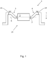
- Fig. 1 shows the measuring device 1 with the flow meter 2, which in this embodiment is a nuclear magnetic flow meter, the inlet pipe 3 and the outlet pipe 4.
- the flow meter 2 has the measuring tube 5 and the measuring tube 5 is connected to the inlet pipe 3 and connected to the outlet pipe 4.
- the measuring tube 5 is straight and has the measuring tube longitudinal axis 6, wherein the measuring tube longitudinal axis 6 is aligned perpendicular to the gravitational field vector 7.
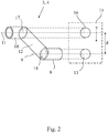
- the inlet pipe 3 and the outlet pipe 4 are formed identically in this embodiment and in Fig. 2 shown. They each have a first Pipe segment 8 with a first pipe segment longitudinal axis 9, a second pipe segment 10 with a second pipe segment longitudinal axis 11 and a third pipe segment 12.
- the first pipe segment 8 of the inlet pipe 3 and the outlet pipe 4 is connected to the measuring tube 5
- the first pipe segment 8 and the second pipe segment 10 are interconnected by the third pipe segment 12 and are the first pipe segment longitudinal axis 9 and the second pipe segment longitudinal axis 11 with a Pipe segment distance d along the Erdheefeldvektor 7 spaced and aligned parallel to each other.
- the projection 13 of the first pipe inner cross-sectional area 14 of the first pipe segment 8 on the projection plane 15 and the projection 16 of the second pipe inner cross-sectional area 17 of the second pipe segment 10 on the projection plane 15 no intersection in the projection plane 15.
- the projection plane is aligned along the gravity field vector 7.
- valve 18 is also in the second tube segment 10 of the inlet pipe 3 and in the second pipe segment 10 of the outlet pipe 4, the valve 19 is arranged.
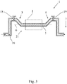
- Fig. 3 and 4 are sectional views of the measuring device 1 and show this in operation.
- the medium 20 flows first through the inlet pipe 3, then through the measuring tube 5 and finally through the outlet pipe 4.
- Fig. 4 shows the measuring device 1 when the flow of the medium 20 has stopped.
- the inlet pipe 3, the measuring tube 5 and the outlet pipe 4 form the siphon 21.
- the siphon 21 is designed and aligned with respect to the Erdheefeldvektor 7 that when first the medium 20 through the siphon 21st flows and then the cause for the flow of the medium 20 stops, the measuring tube 5 is completely filled with the stationary medium 20.
- the pipe segment distance d between the first pipe segment longitudinal axes 9 and the second pipe segment longitudinal axes 11 is determined in such a way taking into account an assumed maximum flow rate with assumed properties of the medium 20, that when the medium 20 first through the inlet pipe 3, the measuring tube 5 and the outlet pipe 4 with the assumed maximum flow velocity flows and then the cause for the flow of the medium 20 stops, the measuring tube 5 is completely filled with the stationary medium 20.
- the third tube segment 12 of the inlet tube 3 and the third tube segment 12 of the outlet tube 4 are arranged obliquely with respect to the gravitational field vector 7 such that the tube segments 12 form a ramp for the medium 20 in the opposite direction to the gravitational field vector 7, so that the medium 20 is slowed down.
- valves 18, 19 thereby control the flow of the medium 20 through the siphon 21.
- the valves 18, 19 are opened, the medium 20 flows through the measuring tube 5 and closed valves 18, 19 cause cessation of the cause of the flow in the measuring tube.
- the medium 20 is not flowed through the inlet pipe 3, the measuring tube 5 and the outlet pipe 4 and are carried out by the flowmeter 2 measurements on the stationary in the measuring tube 5 medium 20.
- the medium 20 is not flowed by both the valve 18 and the valve 19 are closed.
- the accuracy of the measurements from the first method step is increased using the measurements from the second method step.
Landscapes
- Physics & Mathematics (AREA)
- Fluid Mechanics (AREA)
- General Physics & Mathematics (AREA)
- Measuring Volume Flow (AREA)
Abstract
Description
- Die Erfindung betrifft zum einen eine Messvorrichtung mit einem Durchflussmessgerät, einem Einlaufrohr und einem Auslaufrohr, wobei das Durchflussmessgerät ein Messrohr aufweist und das Messrohr mit dem Einlaufrohr und dem Auslaufrohr verbunden ist. Darüber hinaus betrifft die Erfindung auch ein Verfahren zum Betreiben einer Messvorrichtung.
- Ein Durchflussmessgerät mit einem Messrohr misst den Durchfluss eines Mediums durch das Messrohr. Bei dem Medium kann es sich entweder um ein einphasiges oder um ein mehrphasiges Medium handeln. Ein einphasiges Medium umfasst eine einzige Phase und ein mehrphasiges Medium umfasst mehrere Phasen. Darüber hinaus kann ein Medium auch noch feste Bestandteile umfassen. Der Durchfluss einer Phase durch ein Messrohr bezieht sich entweder auf einen Volumendurchfluss oder auf einen Massedurchfluss der Phase. Wenn ein Durchflussmessgerät unmittelbar einen Volumendurchfluss einer Phase eines Mediums misst, kann aus dem Volumendurchfluss unter Verwendung der Dichte der Phase der Massedurchfluss berechnet werden. Entsprechend kann, wenn ein Durchflussmessgerät unmittelbar einen Massedurchfluss einer Phase misst, aus dem Massedurchfluss unter Verwendung der Dichte der Phase der Volumendurchfluss der Phase bestimmt werden.
- Bei der Messvorrichtung sind sowohl das Einlaufrohr als auch das Auslaufrohr derart mit dem Messrohr verbunden, dass ein strömendes Medium zunächst durch das Einlaufrohr, dann durch das Messrohr und schließlich durch das Auslaufrohr strömt. Dabei strömt das Medium unmittelbar aus dem Einlaufrohr in das Messrohr und unmittelbar aus dem Messrohr in das Auslaufrohr.
- Die Bestimmung des Durchflusses eines Mediums durch ein Messrohr erfordert die Kenntnis bestimmter Eigenschaften des Mediums. Weist das Medium zum Beispiel mehrere Phasen auf, müssen individualisierende Eigenschaften der einzelnen Phasen bekannt sein, welche die einzelnen Phasen für ein Durchflussmessgerät unterscheidbar machen, damit das Durchflussmessgerät die Anteile der einzelnen Phasen an dem Medium und die Durchflüsse der einzelnen Phasen bestimmen kann. Die Eigenschaften sind oftmals vom Druck und/oder der Temperatur des Mediums abhängig, weshalb diese Eigenschaften am Betriebsort eines Durchflussmessgeräts zu bestimmen sind und nicht an anderer Stelle während einer Kalibrierung bestimmt werden können. Die Bestimmung dieser Eigenschaften kann zum Beispiel durch Messungen eines Durchflussmessgeräts am im Messrohr stillstehenden Medium erfolgen. Das gilt insbesondere für die flüssigen Bestandteile des Mediums. Oftmals ist am Betriebsort eines Durchflussmessgeräts durch die Einbauposition des Durchflussmessgeräts jedoch nicht gewährleistet, dass, wenn das Medium nicht durch das Messrohr des Durchflussmessgeräts geströmt wird, insbesondere die flüssigen Bestandteile des Mediums im Messrohr verweilen, so dass das Durchflussmessgerät Messungen an dem im Messrohr stillstehenden Medium durchführen kann.
- Eine Aufgabe der vorliegenden Erfindung ist daher die Angabe einer Messvorrichtung, die Messungen eines Durchflussmessgeräts insbesondere an den flüssigen Bestandteilen eines Mediums im Messrohr unabhängig davon ermöglicht, ob das Medium strömt oder stillsteht, wobei das Messrohr bei stillstehendem Medium vollständig zumindest mit den flüssigen Bestandteilen des Mediums gefüllt ist.
- Die Aufgabe ist zunächst und im Wesentlichen dadurch gelöst, dass das Einlaufrohr, das Messrohr und das Auslaufrohr einen Siphon bilden. Dabei ist der Siphon derart ausgebildet und derart in Bezug auf den Erdschwerefeldvektor ausgerichtet, dass, wenn zunächst ein Medium durch den Siphon strömt und dann das Strömen des Mediums aufhört, das Messrohr vollständig mit dem stillstehenden Medium gefüllt ist, und zwar zumindest mit den flüssigen Bestandteilen des Mediums. Das Strömen des Mediums hört dann im Siphon auf, wenn die Ursache für die Strömung im Siphon aufhört. Somit ermöglicht die erfindungsgemäße Messvorrichtung, dass das Durchflussmessgerät am im Messrohr stillstehenden Medium Messungen durchführen kann. Die Messungen erfolgen dabei für gewöhnlich bei der Temperatur und/oder beim Druck des Mediums am Betriebsort des Durchflussmessgeräts. Insbesondere der Umstand, dass Messungen für gewöhnlich bei der Temperatur des Mediums am Betriebsort vom Durchflussmessgerät durchgeführt werden, ist dadurch gewährleistet, dass die Messungen zeitlich unmittelbar nach dem Aufhören des Strömens des Mediums durch das Messrohr ausgeführt werden.
- In einer Ausgestaltung der erfindungsgemäßen Messvorrichtung ist vorgesehen, dass das Durchflussmessgerät ein kernmagnetisches Durchflussmessgerät ist. Ein kernmagnetisches Durchflussmessgerät nutzt zur Analyse und insbesondere zur Durchflussmessung eines Mediums durch das Messrohr kernmagnetische Resonanzmessverfahren. Kernmagnetische Resonanzmessverfahren beeinflussen die Präzession von Atomkernen eines Mediums bei Anwesenheit eines makroskopischen Magnetfelds durch Anregung der Atomkerne mittels eines gesteuerten Magnetfelds und werten die Wirkung der Anregung auf die Atomkerne aus. Ein kernmagnetisches Durchflussmessgerät weist deshalb zur Erzeugung eines Magnetfelds in einem durch das Messrohr strömenden Medium eine Magnetisierungsvorrichtung und zur Anregung des Mediums im Messrohr und zur Messung der Wirkung der Anregung auf das Medium im Messrohr eine Messvorrichtung auf.
- Die Atomkerne der Elemente, die einen Kernspin besitzen, besitzen auch ein durch den Kernspin hervorgerufenes magnetisches Moment. Der Kernspin kann als ein durch einen Vektor beschreibbarer Drehimpuls aufgefasst werden und entsprechend kann auch das magnetische Moment durch einen Vektor beschrieben werden, der parallel zum Vektor des Drehimpulses ist. Der Vektor des magnetischen Moments eines Atomkerns richtet sich bei Anwesenheit eines makroskopischen Magnetfelds wie dem durch die Magnetisierungsvorrichtung erzeugten parallel zum Vektor des makroskopischen Magnetfelds an der Stelle des Atomkerns aus. Dabei präzessiert der Vektor des magnetischen Moments des Atomkerns um den Vektor des makroskopischen Magnetfelds an der Stelle des Atomkerns. Die Frequenz der Präzession wird als Lamorfrequenz ωL bezeichnet und ist proportional zum Betrag der Magnetfeldstärke B. Die Lamorfrequenz berechnet sich gemäß ωL = y • B. Darin ist γ das gyromagnetische Verhältnis, welches für Wasserstoffatomkerne maximal ist.
- Voraussetzung für die Analyse und insbesondere für die Durchflussmessung eines Mediums durch ein kernmagnetisches Durchflussmessgerät unter Ausnutzung von kernmagnetischen Resonanzen ist, dass die zu analysierenden Phasen eines Mediums von dem kernmagnetischen Durchflussmessgerät zu unterscheidbaren kernmagnetischen Resonanzen angeregt werden können. Dafür ist die Kenntnis individualisierender Eigenschaften der einzelnen Phasen des Mediums erforderlich. Zu diesen zählen zum Beispiel die Spin-Spin- und die Spin-Gitter-Relaxationszeitkonstante. Diese Eigenschaften sind für gewöhnlich vom Druck und/oder der Temperatur des Mediums abhängig, weshalb die Eigenschaften am Betriebsort eines Durchflussmessgeräts zu bestimmen sind. Die Eigenschaften können zum Beispiel durch Messungen vom kernmagnetischen Durchflussmessgerät am im Messrohr stillstehenden Medium bestimmt werden.
- Die Durchflussmessung kann die Strömungsgeschwindigkeiten der einzelnen Phasen des Mediums und die relativen Anteile der einzelnen Phasen am mehrphasigen Medium umfassen. Kernmagnetische Durchflussmessgeräte können zum Beispiel zur Analyse des aus Ölquellen geförderten mehrphasigen Mediums eingesetzt werden. Dieses Medium besteht im Wesentlichen aus den Phasen Erdöl, Erdgas und Salzwasser, wobei alle Phasen Wasserstoffatomkerne enthalten.
- Grundsätzlich führt das Durchflussmessgerät Messungen am im Messrohr stillenstehenden Medium, unmittelbar nachdem das Strömen des Mediums aufgehört hat, durch. Das gewährleistet, dass die Messungen nicht dadurch beeinflusst sind, dass sich die einzelnen Phasen bei einem mehrphasigen Medium trennen und die Messungen beeinflussen. Um die Beeinflussung von Messungen durch eine Trennung der einzelnen Phasen des mehrphasigen Mediums zumindest zu vermindern, ist in einer weiteren Ausgestaltung der Messvorrichtung vorgesehen, dass das Messrohr gerade ist, eine Messrohrlängsachse aufweist und die Messrohrlängsachse senkrecht zum Erdschwerefeldvektor ausgerichtet ist. Bei dieser Ausgestaltung ist sichergestellt, dass sich die einzelnen Phasen nach der Trennung in Bezug auf den Erdschwerefeldvektor übereinander anordnen, so dass die Verteilung der einzelnen Phasen entlang der Messrohrlängsachse konstant ist, wodurch Messungen am Medium insbesondere durch kernmagnetische Durchflussmessgeräte in Bezug auf ein Messvolumen in seiner Gesamtheit nicht beeinflusst werden.
- In einer weiteren Ausgestaltung ist vorgesehen, dass das Einlaufrohr und das Auslaufrohr jeweils ein erstes Rohrsegment mit einer ersten Rohrsegmentlängsachse, ein zweites Rohrsegment mit einer zweiten Rohrsegmentlängsachse und ein drittes Rohrsegment aufweisen. Dabei ist jeweils das erste Rohrsegment mit dem Messrohr verbunden, sind das erste Rohrsegment und das zweite Rohrsegment durch das dritte Rohrsegment miteinander verbunden und sind die erste Rohrsegmentlängsachse und die zweite Rohrsegmentlängsachse mit einem Rohrsegmentabstand beabstandet und parallel zueinander ausgerichtet. Der Rohrsegmentabstand ist dabei derart gewählt, dass bei einem stillstehenden Medium das Messrohr zumindest mit den flüssigen Bestandteilen des Mediums vollständig gefüllt ist.
- Wenn ein Medium zunächst durch das Einlaufrohr, das Messrohr und das Auslaufrohr strömt und dann die Ursache für das Strömen des Mediums zumindest im Messrohr aufhört, so versucht das Medium aufgrund seiner Massenträgheit weiter zu strömen. Das kann dazu führen, dass das Medium auch aus dem Messrohr hinausströmt, so dass das Messrohr nicht mehr bei stillstehendem Medium vollständig gefüllt ist. Deshalb ist in einer Weiterbildung der vorangehenden Ausgestaltung vorgesehen, dass der Rohrsegmentabstand derart unter Berücksichtigung einer angenommenen maximalen Strömungsgeschwindigkeit und angenommener Eigenschaften eines Mediums bestimmt ist, dass, wenn das Medium zunächst durch das Einlaufrohr, das Messrohr und das Auslaufrohr mit der angenommenen maximalen Strömungsgeschwindigkeit strömt und dann die Ursache für das Strömen des Mediums aufhört, das Messrohr vollständig mit dem stillstehenden Medium gefüllt ist. Bei einer der angenommenen Eigenschaften des Mediums handelt es sich zum Beispiel um die Dichte des Mediums. Aus der Dichte des Mediums und dem Volumen des Mediums in der Messvorrichtung kann zum Beispiel die Trägheit des strömenden Mediums bestimmt werden. Dabei ist es vorteilhaft, wenn zumindest das dritte Rohrsegment des Auslaufrohrs derart schräg angeordnet ist, dass es für das strömende Medium eine Rampe in entgegengesetzter Richtung zum Erdschwerefeldvektor bildet, so dass das Medium abgebremst wird.
- In einer weiteren Ausgestaltung ist vorgesehen, dass das Einlaufrohr und das Auslaufrohr jeweils ein erstes Rohrsegment, ein zweites Rohrsegment und ein drittes Rohrsegment aufweisen. Dabei ist das erste Rohrsegment mit dem Messrohr verbunden, sind das erste Rohrsegment und das zweite Rohrsegment durch das dritte Rohrsegment miteinander verbunden und weisen eine Projektion einer ersten Rohrinnenquerschnittsfläche des ersten Rohrsegments auf eine Projektionsebene und eine Projektion einer zweiten Rohrinnenquerschnittsfläche des zweiten Rohrsegments auf die Projektionsebene keine Schnittfläche in der Projektionsebene auf. Somit sind die Projektion der ersten Rohrinnenquerschnittsfläche und die Projektion der zweiten Rohrinnenquerschnittsfläche auf der Projektionsebene separat. Dadurch ist gewährleistet, dass ein Medium das Messrohr nach dem Aufhören der Ursache für die Strömung des Mediums auch vollständig füllt und nicht durch das Einlaufrohr oder das Auslaufrohr aus dem Messrohr abfließt.
- In einer weiteren Ausgestaltung ist vorgesehen, dass sowohl im Einlaufrohr als auch im Auslaufrohr jeweils ein Ventil angeordnet ist oder das entweder im Einlaufrohr oder im Auslaufrohr ein Ventil angeordnet ist, um die Strömung eines Mediums durch das Messrohr zu steuern. Das Ventil bzw. die Ventile sind ausgebildet, das Strömen eines Mediums durch das Messrohr derart zu beeinflussen, dass das Medium durch das Messrohr strömt oder ein Strömen des Mediums im Messrohr aufhört. Das Ventil bzw. die Ventile sind somit die Ursache, wenn das Strömen des Mediums aufhört.
- In einer Weiterbildung der vorangehenden Ausgestaltung der Messvorrichtung deren Einlaufrohr und Auslaufrohr jeweils ein erstes Rohrsegment, ein zweites Rohrsegment und ein drittes Rohrsegment aufweisen, wobei das erste Rohrsegment mit dem Messrohr verbunden ist und das erste Rohrsegment und das zweite Rohrsegment durch das dritte Rohrsegment miteinander verbunden sind, ist vorgesehen, dass das Ventil im Einlaufrohr und das Ventil im Auslaufrohr im jeweils dritten Rohrsegment angeordnet sind oder dass das Ventil im Einlaufrohr oder das Ventil im Auslaufrohr im entsprechenden dritten Rohrsegment angeordnet ist.
- Gemäß einer weiteren Lehre betrifft die Erfindung auch ein Verfahren zum Betreiben einer erfindungsgemäßen Messvorrichtung. Das Verfahren weist die folgenden Verfahrensschritte auf:
- In einem ersten Verfahrensschritt wird ein Medium durch das Einlaufrohr, das Messrohr und das Auslaufrohr geströmt und werden von dem Durchflussmessgerät Messungen an dem im Messrohr strömenden Medium durchgeführt. Wenn das strömende Medium ein mehrphasiges Medium ist, handelt es sich bei den Messungen zum Beispiel um Messungen zur Bestimmung der Anteile der einzelnen Phasen am mehrphasigen Medium und/oder um Messungen zur Bestimmung der Durchflüsse der einzelnen Phasen durch das Messrohr.
- In einem zweiten Verfahrensschritt wird das Medium nicht durch das Einlaufrohr, das Messrohr und das Auslaufrohr geströmt und werden von dem Durchflussmessgerät an dem im Messrohr stillstehenden Medium Messungen durchgeführt. Bei diesen Messungen handelt es sich zum Beispiel um Messungen zur Bestimmung der genannten individualisierenden Eigenschaften der einzelnen Phasen des mehrphasigen Mediums, welche die einzelnen Phasen für das Durchflussmessgerät unterscheidbar machen, damit das Durchflussmessgerät die Anteile der einzelnen Phasen an dem Medium und die Durchflüsse der einzelnen Phasen bestimmen kann.
- In einem dritten Verfahrensschritt wird die Genauigkeit der Messungen aus dem ersten Verfahrensschritt unter Verwendung der Messungen aus dem zweiten Verfahrensschritt gesteigert.
- Im Einzelnen ist eine Vielzahl von Möglichkeiten gegeben, die erfindungsgemäße Messvorrichtung und das erfindungsgemäße Verfahren auszugestalten und weiterzubilden. Dazu wird verwiesen sowohl auf die dem Patentanspruch 1 nachgeordneten Patentansprüche als auch auf die nachfolgende Beschreibunge eines bevorzugten Ausführungsbeispiels in Verbindung mit der Zeichnung. In der Zeichnung zeigt
- Fig. 1
- ein Ausführungsbeispiel einer Messvorrichtung,
- Fig. 2
- eine Schnittdarstellung der Messvorrichtung auf
Fig. 1 mit einem strömenden Medium, - Fig. 3
- die Schnittdarstellung aus
Fig. 2 mit einem stillstehenden Medium, - Fig. 4
- ein Einlauf- oder Auslaufrohr mit einer Projektion und
- Fig. 5
- einen Ablaufplan eines Verfahrens.
-
Fig. 1 zeigt die Messvorrichtung 1 mit dem Durchflussmessgerät 2, wobei es sich bei diesem in diesem Ausführungsbeispiel um ein kernmagnetisches Durchflussmessgerät handelt, dem Einlaufrohr 3 und dem Auslaufrohr 4. Das Durchflussmessgerät 2 weist das Messrohr 5 auf und das Messrohr 5 ist mit dem Einlaufrohr 3 und mit dem Auslaufrohr 4 verbunden. In diesem Ausführungsbeispiel ist das Messrohr 5 gerade und weist die Messrohrlängsachse 6 auf, wobei die Messrohrlängsachse 6 senkrecht zum Erdschwerefeldvektor 7 ausgerichtet ist. - Das Einlaufrohr 3 und das Auslaufrohr 4 sind in diesem Ausführungsbeispiel identisch ausgebildet und in
Fig. 2 dargestellt. Sie weisen jeweils ein erstes Rohrsegment 8 mit einer ersten Rohrsegmentlängsachse 9, ein zweites Rohrsegment 10 mit einer zweiten Rohrsegmentlängsachse 11 und ein drittes Rohrsegment 12 auf. Dabei ist jeweils das erste Rohrsegment 8 des Einlaufrohrs 3 und des Auslaufrohrs 4 mit dem Messrohr 5 verbunden, sind das erste Rohrsegment 8 und das zweite Rohrsegment 10 durch das dritte Rohrsegment 12 miteinander verbunden und sind die erste Rohrsegmentlängsachse 9 und die zweite Rohrsegmentlängsachse 11 mit einem Rohrsegmentabstand d entlang dem Erdschwerefeldvektor 7 beabstandet und parallel zueinander ausgerichtet. Darüber hinaus weisen in diesem Ausführungsbeispiel die Projektion 13 der ersten Rohrinnenquerschnittsfläche 14 des ersten Rohrsegments 8 auf die Projektionsebene 15 und die Projektion 16 der zweiten Rohrinnenquerschnittsfläche 17 des zweiten Rohrsegments 10 auf die Projektionsebene 15 keine Schnittfläche in der Projektionsebene 15 auf. Die Projektionsebene ist dabei entlang dem Erschwerefeldvektor 7 ausgerichtet. - In diesem Ausführungsbeispiel der Messvorrichtung 1 ist darüber hinaus im zweiten Rohrsegment 10 des Einlaufrohrs 3 das Ventil 18 und ist im zweiten Rohrsegment 10 des Auslaufrohrs 4 das Ventil 19 angeordnet.
- Die
Fig. 3 und4 sind Schnittdarstellungen der Messvorrichtung 1 und zeigen diese im Betrieb. InFig. 3 strömt das Medium 20 zuerst durch das Einlaufrohr 3, dann durch das Messrohr 5 und schließlich durch das Auslaufrohr 4.Fig. 4 zeigt die Messeinrichtung 1, wenn das Strömen des Mediums 20 aufgehört hat. Unabhängig von dem Ausführungsbeispiel der Messvorrichtung 1 bilden das Einlaufrohr 3, das Messrohr 5 und das Auslaufrohr 4 den Siphon 21. Der Siphon 21 ist dabei derart ausgebildet und in Bezug auf den Erdschwerefeldvektor 7 ausgerichtet, dass, wenn zunächst das Medium 20 durch den Siphon 21 strömt und dann die Ursache für das Strömen des Mediums 20 aufhört, das Messrohr 5 vollständig mit dem stillstehenden Medium 20 gefüllt ist. - Der Rohrsegmentabstand d zwischen den ersten Rohrsegmentlängsachsen 9 und den zweiten Rohrsegmentlängsachsen 11 ist derart unter Berücksichtigung einer angenommenen maximalen Strömungsgeschwindigkeit mit angenommenen Eigenschaften des Mediums 20 bestimmt, dass, wenn das Medium 20 zunächst durch das Einlaufrohr 3, das Messrohr 5 und das Auslaufrohr 4 mit der angenommenen maximalen Strömungsgeschwindigkeit strömt und dann die Ursache für das Strömen des Mediums 20 aufhört, das Messrohr 5 vollständig mit dem stillstehenden Medium 20 gefüllt ist.
- Zusätzlich sind das dritte Rohrsegment 12 des Einlaufrohrs 3 und das dritte Rohrsegment 12 des Auslaufrohrs 4 derart schräg in Bezug auf den Erdschwerefeldvektor 7 angeordnet, dass die Rohrsegmente 12 für das Medium 20 eine Rampe in entgegengesetzter Richtung zum Erdschwerefeldvektor 7 bildet, so dass das Medium 20 abgebremst wird.
- Die Ventile 18, 19 steuern dabei das Strömen des Mediums 20 durch den Siphon 21. Wenn die Ventile 18, 19 geöffnet sind, strömt das Medium 20 durch das Messrohr 5 und geschlossene Ventile 18, 19 bewirken ein Aufhören der Ursache der Strömung im Messrohr.
- Die Messvorrichtung 1 führt im Betrieb das im Ablaufplan in
Fig. 5 dargestellte Verfahren mit den folgenden Verfahrensschritten aus: - In dem ersten Verfahrensschritt 22 wird das Medium 20 durch das Einlaufrohr 3, das Messrohr 5 und das Auslaufrohr 4 geströmt und werden von dem Durchflussmessgerät 2 Messungen an dem im Messrohr 5 strömenden Medium 20 durchgeführt. Die Strömung des Mediums 20 wird dabei durch geöffnete Ventile 18, 19 eingestellt.
- In dem zweiten Verfahrensschritt 23 wird das Medium 20 nicht durch das Einlaufrohr 3, das Messrohr 5 und das Auslaufrohr 4 geströmt und werden von dem Durchflussmessgerät 2 Messungen an dem im Messrohr 5 stillstehenden Medium 20 durchgeführt. Das Medium 20 wird nicht geströmt, indem sowohl das Ventil 18 als auch das Ventil 19 geschlossen sind.
- In dem dritten Verfahrensschritt 24 wird die Genauigkeit der Messungen aus dem ersten Verfahrensschritt unter Verwendung der Messungen aus dem zweiten Verfahrensschritt gesteigert.
-
- 1
- Messvorrichtung
- 2
- Durchflussmessgerät
- 3
- Einlaufrohr
- 4
- Auslaufrohr
- 5
- Messrohr
- 6
- Messrohrlängsachse
- 7
- Erdschwerefeldvektor
- 8
- Erstes Rohrsegment
- 9
- Erste Rohrsegmentlängsachse
- 10
- Zweites Rohrsegment
- 11
- Zweite Rohrsegmentlängsachse
- 12
- Drittes Rohrsegment
- 13
- Projektion der ersten Rohrinnenquerschnittsfläche
- 14
- Erste Rohrinnenquerschnittsfläche
- 15
- Projektionsebene
- 16
- Projektion der zweiten Rohrinnenquerschnittsfläche
- 17
- Zweite Rohrinnenquerschnittsfläche
- 18
- Ventil
- 19
- Ventil
- 20
- Medium
- 21
- Siphon
- 22
- Erster Verfahrensschritt
- 23
- Zweiter Verfahrensschritt
- 24
- Dritter Verfahrensschritt
- d
- Rohrsegmentabstand
Claims (10)
- Messvorrichtung (1) mit einem Durchflussmessgerät (2), einem Einlaufrohr (3) und einem Auslaufrohr (4),
wobei das Durchflussmessgerät (2) ein Messrohr (5) aufweist und das Messrohr (5) mit dem Einlaufrohr (3) und mit dem Auslaufrohr (4) verbunden ist,
dadurch gekennzeichnet,
dass das Einlaufrohr (3), das Messrohr (5) und das Auslaufrohr (4) einen Siphon (21) bilden, wobei der Siphon (21) derart ausgebildet und in Bezug auf den Erdschwerefeldvektor (7) ausgerichtet ist, dass, wenn zunächst ein Medium (20) durch den Siphon (21) strömt und dann das Strömen des Mediums (20) aufhört, das Messrohr (5) vollständig mit dem stillstehenden Medium (20) gefüllt ist. - Messvorrichtung (1) nach Anspruch 1, dadurch gekennzeichnet, dass das Durchflussmessgerät (2) ein kernmagnetisches Durchflussmessgerät ist.
- Messvorrichtung (1) nach Anspruch 1 oder 2, dadurch gekennzeichnet, dass das Messrohr (5) gerade ist, eine Messrohrlängsachse (6) aufweist und die Messrohrlängsachse (6) senkrecht zum Erdschwerefeldvektor (7) ausgerichtet ist.
- Messvorrichtung (1) nach einem der Ansprüche 1 bis 3, dadurch gekennzeichnet, dass das Einlaufrohr (3) und das Auslaufrohr (4) jeweils ein erstes Rohrsegment (8) mit einer ersten Rohrsegmentlängsachse (9), ein zweites Rohrsegment (10) mit einer zweiten Rohrsegmentlängsachse (11) und ein drittes Rohrsegment (12) aufweisen, wobei das erste Rohrsegment (8) mit dem Messrohr (5) verbunden ist, das erste Rohrsegment (8) und das zweite Rohrsegment (10) durch das dritte Rohrsegment (12) miteinander verbunden sind und die erste Rohrsegmentlängsachse (9) und die zweite Rohrsegmentlängsachse (11) mit einem Rohrsegmentabstand (d) beabstandet und parallel zueinander sind.
- Messvorrichtung (1) nach Anspruch 4, dadurch gekennzeichnet, dass der Rohrsegmentabstand (d) derart unter Berücksichtigung einer angenommenen maximalen Strömungsgeschwindigkeit und angenommener Eigenschaften eines Mediums (20) bestimmt ist, dass, wenn das Medium (20) zunächst durch das Einlaufrohr (3), das Messrohr (5) und das Auslaufrohr (4) mit der angenommenen maximalen Strömungsgeschwindigkeit strömt und dann die Ursache für das Strömen des Medium (20) aufhört, das Messrohr (5) vollständig mit dem stillstehenden Medium (20) gefüllt ist.
- Messvorrichtung (1) nach einem der Ansprüche 1 bis 5, dadurch gekennzeichnet, dass das Einlaufrohr (3) und das Auslaufrohr (4) jeweils ein erstes Rohrsegment (8), ein zweites Rohrsegment (10) und ein drittes Rohrsegment (12) ausweisen, wobei das erste Rohrsegment (8) mit dem Messrohr (5) verbunden ist, das erste Rohrsegment (8) und das zweite Rohrsegment (10) durch das dritte Rohrsegment (12) miteinander verbunden sind, eine Projektion (13) einer ersten Rohrinnenquerschnittsfläche (14) des ersten Rohrsegments (8) auf eine Projektionsebene (15) und eine Projektion (16) einer zweiten Rohrinnenquerschnittsfläche (17) des zweiten Rohrsegments (10) auf die Projektionsebene (15) keine Schnittfläche in der Projektionsebene (15) aufweisen.
- Messvorrichtung (1) nach einem der Ansprüche 1 bis 6, dadurch gekennzeichnet, dass im Einlaufrohr (3) und im Auslaufrohr (4) jeweils ein Ventil (18, 19) angeordnet ist oder dass im Einlaufrohr (3) oder im Auslaufrohr (4) ein Ventil (18, 19) angeordnet ist, um die Strömung eines Mediums (20) durch das Messrohr (5) zu steuern.
- Messvorrichtung (1) nach Anspruch 7 und einem der Ansprüche 4 bis 6, dadurch gekennzeichnet, dass das Ventil (18) im Einlaufrohr (3) und das Ventil (19) im Auslaufrohr (4) im jeweiligen dritten Rohrsegment (12) angeordnet sind oder dass das Ventil (18) im Einlaufrohr (3) oder das Ventil (19) im Auslaufrohr (4) im entsprechenden dritten Rohrsegment (12) angeordnet ist.
- Verfahren zum Betreiben einer Messvorrichtung (1) mit einem Durchflussmessgerät (2), einem Einlaufrohr (3) und einem Auslaufrohr (4),
wobei das Durchflussmessgerät (2) ein Messrohr (5) aufweist und das Messrohr (5) mit dem Einlaufrohr (3) und mit dem Auslaufrohr (4) verbunden ist,
wobei das Einlaufrohr (3), das Messrohr (5) und das Auslaufrohr (4) einen Siphon (21) bilden, der Siphon (21) derart ausgebildet und in Bezug auf den Erdschwerefeldvektor (7) ausgerichtet ist, dass, wenn zunächst ein Medium (20) durch den Siphon (21) strömt und dann das Strömen des Mediums (20) aufhört, das Messrohr (5) vollständig mit dem stillstehenden Medium (20) gefüllt ist und
wobei das Verfahren die folgenden Verfahrensschritte aufweist:In einem ersten Verfahrensschritt (22) wird das Medium (20) durch das Einlaufrohr(3), das Messrohr (5) und das Auslaufrohr (4) geströmt und werden von dem Durchflussmessgerät (2) Messungen an dem im Messrohr (5) strömenden Medium (20) durchgeführt,in einem zweiten Verfahrensschritt (23) wird das Medium (20) nicht durch das Einlaufrohr (3), das Messrohr (5) und das Auslaufrohr (4) geströmt und werden von dem Durchflussmessgerät (2) an dem im Messrohr (5) stillstehenden Medium (20) Messungen durchgeführt undin einem dritten Verfahrensschritt (24) wird die Genauigkeit der Messungen aus dem ersten Verfahrensschritt (22) unter Verwendung der Messungen aus dem zweiten Verfahrensschritt (23) gesteigert. - Verfahren nach Anspruch 9, wobei die Messvorrichtung (1) gemäß einem der Ansprüche 2 bis 8 ausgebildet ist.
Applications Claiming Priority (1)
| Application Number | Priority Date | Filing Date | Title |
|---|---|---|---|
| DE102016104781.3A DE102016104781A1 (de) | 2016-03-15 | 2016-03-15 | Messvorrichtung mit einem Durchflussmessgerät und Verfahren zum Betreiben einer Messvorrichtung |
Publications (2)
| Publication Number | Publication Date |
|---|---|
| EP3220107A1 true EP3220107A1 (de) | 2017-09-20 |
| EP3220107B1 EP3220107B1 (de) | 2021-04-14 |
Family
ID=58228013
Family Applications (1)
| Application Number | Title | Priority Date | Filing Date |
|---|---|---|---|
| EP17159164.7A Active EP3220107B1 (de) | 2016-03-15 | 2017-03-03 | Verfahren zur auslegung einer messvorrichtung und verfahren zum betreiben einer messvorrichtung |
Country Status (3)
| Country | Link |
|---|---|
| US (1) | US10996090B2 (de) |
| EP (1) | EP3220107B1 (de) |
| DE (1) | DE102016104781A1 (de) |
Citations (7)
| Publication number | Priority date | Publication date | Assignee | Title |
|---|---|---|---|---|
| US1935667A (en) * | 1931-07-17 | 1933-11-21 | Sf Bowser & Co Inc | Means for preventing error in meters |
| US3138291A (en) * | 1962-11-23 | 1964-06-23 | Socony Mobil Oil Co Inc | Tank truck air eliminator system |
| DE1176886B (de) * | 1956-10-02 | 1964-08-27 | Gerdts Gustav F Kg | Mess- und/oder Regeleinrichtung fuer gas- oder dampfdurchsetzte stroemende Medien |
| US4134294A (en) * | 1976-12-27 | 1979-01-16 | Geoservices | Device for simultaneously measuring various parameters of the drilling fluid |
| DD260339A1 (de) * | 1987-05-08 | 1988-09-21 | Adw Der Ddr Inst F Geographie | Messeinrichtung zur bestimmung von sickervorgaengen an der grenze zwischen oberflaechen- und grundwasser |
| DE29514088U1 (de) * | 1995-09-02 | 1995-11-02 | Botsch, Bertram, Dipl.-Ing., 76227 Karlsruhe | Vorrichtung zur Durchflußmessung im Auslauf von flüssigkeitsgefüllten Behältern und Becken, vorzugsweise in Kläranlagen, Regenwasserbehandlungsanlagen und Wasserreinigungsanlagen |
| US20130014570A1 (en) * | 2011-07-12 | 2013-01-17 | Korea Institute Of Geoscience And Mineral Resources | Automatic seepage meter |
Family Cites Families (10)
| Publication number | Priority date | Publication date | Assignee | Title |
|---|---|---|---|---|
| US3314290A (en) * | 1965-07-26 | 1967-04-18 | Technion Res & Dev Foundation | Shunt flow meter |
| FR2300995A1 (fr) * | 1975-02-13 | 1976-09-10 | Gremeaux Jean | Procede et dispositif pour la mesure d'un debit de metal liquide a haute temperature |
| US4697147A (en) * | 1985-11-14 | 1987-09-29 | Metriflow, Inc. | Blood flow imaging using a CW NMR technique |
| US5333496A (en) * | 1992-03-09 | 1994-08-02 | Fenelon Paul J | In-line parallel proportionally partitioned by-pass metering device and method |
| US5463906A (en) * | 1994-01-24 | 1995-11-07 | Triton Technology, Inc. | Interchangeable disposable acoustic for use with an ultrasonic flowmeter, particularly during extracorporeal measurement of blood flow |
| US5748504A (en) * | 1996-06-12 | 1998-05-05 | Welch Allyn, Inc. | Calibration method for use with ultrasonic flowmeters |
| JPH11241932A (ja) * | 1998-02-25 | 1999-09-07 | Toshiba Corp | 非満水式電磁流量計 |
| FR2815120B1 (fr) * | 2000-10-09 | 2002-12-13 | Inst Francais Du Petrole | Methode et dispositif de prelevement d'une emulsion en circulation dans une conduite |
| DE102012013933B4 (de) * | 2012-07-16 | 2023-12-07 | Krohne Ag | Verfahren und Vorrichtung zum Kalibrieren von kernmagnetischen Durchflussmessgeräten |
| DE202013009509U1 (de) * | 2013-10-25 | 2014-03-13 | Dirk Lixfeld | Wartungsfreundliche Sondersiphons in Hygieneausführung, UV-beständig und druckseitig mit doppeltwirkender Kugel für Klimageräte. |
-
2016
- 2016-03-15 DE DE102016104781.3A patent/DE102016104781A1/de not_active Withdrawn
-
2017
- 2017-03-03 EP EP17159164.7A patent/EP3220107B1/de active Active
- 2017-03-09 US US15/454,288 patent/US10996090B2/en active Active
Patent Citations (7)
| Publication number | Priority date | Publication date | Assignee | Title |
|---|---|---|---|---|
| US1935667A (en) * | 1931-07-17 | 1933-11-21 | Sf Bowser & Co Inc | Means for preventing error in meters |
| DE1176886B (de) * | 1956-10-02 | 1964-08-27 | Gerdts Gustav F Kg | Mess- und/oder Regeleinrichtung fuer gas- oder dampfdurchsetzte stroemende Medien |
| US3138291A (en) * | 1962-11-23 | 1964-06-23 | Socony Mobil Oil Co Inc | Tank truck air eliminator system |
| US4134294A (en) * | 1976-12-27 | 1979-01-16 | Geoservices | Device for simultaneously measuring various parameters of the drilling fluid |
| DD260339A1 (de) * | 1987-05-08 | 1988-09-21 | Adw Der Ddr Inst F Geographie | Messeinrichtung zur bestimmung von sickervorgaengen an der grenze zwischen oberflaechen- und grundwasser |
| DE29514088U1 (de) * | 1995-09-02 | 1995-11-02 | Botsch, Bertram, Dipl.-Ing., 76227 Karlsruhe | Vorrichtung zur Durchflußmessung im Auslauf von flüssigkeitsgefüllten Behältern und Becken, vorzugsweise in Kläranlagen, Regenwasserbehandlungsanlagen und Wasserreinigungsanlagen |
| US20130014570A1 (en) * | 2011-07-12 | 2013-01-17 | Korea Institute Of Geoscience And Mineral Resources | Automatic seepage meter |
Also Published As
| Publication number | Publication date |
|---|---|
| EP3220107B1 (de) | 2021-04-14 |
| US10996090B2 (en) | 2021-05-04 |
| US20170268917A1 (en) | 2017-09-21 |
| DE102016104781A1 (de) | 2017-09-21 |
Similar Documents
| Publication | Publication Date | Title |
|---|---|---|
| DE102014010324B3 (de) | Kernmagnetisches Durchflussmessgerät und Verfahren zum Betreiben eines kernmagnetischen Durchflussmessgeräts | |
| DE102004043151B4 (de) | Verfahren und Vorrichtung zum Bestimmen der Geschwindigkeit und von Eigenschaften von strömenden Fluiden unter Verwendung von magnetischen Kernresonanzmessungen | |
| DE102012013933B4 (de) | Verfahren und Vorrichtung zum Kalibrieren von kernmagnetischen Durchflussmessgeräten | |
| DE69607390T2 (de) | Automatisches bohrloch testsystem und verfahren zu seinem betrieb | |
| DE3872882T2 (de) | Mehrphasen-stroemungsmesser. | |
| EP3036511B1 (de) | Kernmagnetisches durchflussmessgerät und verfahren zum betreiben von kernmagnetischen durchflussmessgeräten | |
| EP0615112A1 (de) | Verfahren zur Ermittlung der Ergiebigkeit von Wasser/Öl-Emulsionen fördernden Ölbohrungen sowie Testseparator zur Durchführung des Verfahrens | |
| DE102011077202A1 (de) | Verfahren und Anordnung zur Bestimmung einer Zusammensetzung eines Mehrphasengemischs | |
| EP2641065A1 (de) | Verfahren zum betreiben eines resonanzmesssystems | |
| EP3186596B1 (de) | Verfahren zum betreiben eines kernmagnetischen durchflussmessgeräts und kernmagnetisches durchflussmessgerät | |
| EP2733472B1 (de) | Kernmagnetisches Durchflussmessgerät und Verfahren zum Betreiben von kernmagnetischen Durchflussmessgeräten | |
| DE69910447T2 (de) | Verfahren zum messen des durchflusses der einzelnen phasen in einer multi-phasen strömung und zugehörige vorrichtung | |
| EP3220107B1 (de) | Verfahren zur auslegung einer messvorrichtung und verfahren zum betreiben einer messvorrichtung | |
| EP4083581B1 (de) | Verfahren zum bestimmen eines flüssigkeitsanteils eines strömenden mediums mit einem kernmagnetischen durchflussmessgerät | |
| EP2910906B1 (de) | Verfahren zum Betreiben eines kernmagnetischen Durchflussmessgeräts | |
| EP3252439A2 (de) | Verfahren zum betreiben eines kernmagnetischen durchflussmessgeräts und kernmagnetisches durchflussmessgerät | |
| DE102015005300A1 (de) | Verfahren zum Betreiben eines kernmagnetischen Durchflussmessgeräts | |
| LU87879A1 (de) | Verfahren zur bestimmung des massenflusses der einzelnen komponenten einer mehrkomponentenstroemung | |
| EP3026403B1 (de) | Verfahren zum betreiben eines kernmagnetischen durchflussmessgeräts | |
| DE102016108996A1 (de) | Verfahren zum Betreiben eines kernmagnetischen Durchflussmessgeräts und kernmagnetisches Durchflussmessgerät | |
| AT383683B (de) | Vorrichtung zur probenahme von durch eine fluidstromleitung stroemendem fluid | |
| DE102019125121B4 (de) | Verfahren zur Bestimmung einer abgeleiteten Eigenschaft eines Mediums und kernmagnetisches Messgerät, Computerprogrammprodukt und computerlesbares Speichermedium für ein solches | |
| DE102014009902B3 (de) | Verfahren zum Betreiben eines kernmagnetischen Durchflussmessgeräts | |
| DE102017115807B3 (de) | Kernmagnetisches Messgerät | |
| WO2025256771A1 (de) | Verfahren zum betreiben eines kernmagnetischen durchflussmessgeräts |
Legal Events
| Date | Code | Title | Description |
|---|---|---|---|
| PUAI | Public reference made under article 153(3) epc to a published international application that has entered the european phase |
Free format text: ORIGINAL CODE: 0009012 |
|
| STAA | Information on the status of an ep patent application or granted ep patent |
Free format text: STATUS: THE APPLICATION HAS BEEN PUBLISHED |
|
| AK | Designated contracting states |
Kind code of ref document: A1 Designated state(s): AL AT BE BG CH CY CZ DE DK EE ES FI FR GB GR HR HU IE IS IT LI LT LU LV MC MK MT NL NO PL PT RO RS SE SI SK SM TR |
|
| AX | Request for extension of the european patent |
Extension state: BA ME |
|
| STAA | Information on the status of an ep patent application or granted ep patent |
Free format text: STATUS: REQUEST FOR EXAMINATION WAS MADE |
|
| 17P | Request for examination filed |
Effective date: 20180319 |
|
| RBV | Designated contracting states (corrected) |
Designated state(s): AL AT BE BG CH CY CZ DE DK EE ES FI FR GB GR HR HU IE IS IT LI LT LU LV MC MK MT NL NO PL PT RO RS SE SI SK SM TR |
|
| STAA | Information on the status of an ep patent application or granted ep patent |
Free format text: STATUS: EXAMINATION IS IN PROGRESS |
|
| 17Q | First examination report despatched |
Effective date: 20180905 |
|
| GRAP | Despatch of communication of intention to grant a patent |
Free format text: ORIGINAL CODE: EPIDOSNIGR1 |
|
| STAA | Information on the status of an ep patent application or granted ep patent |
Free format text: STATUS: GRANT OF PATENT IS INTENDED |
|
| RIC1 | Information provided on ipc code assigned before grant |
Ipc: G01F 15/18 20060101ALI20200908BHEP Ipc: G01F 25/00 20060101ALI20200908BHEP Ipc: G01F 1/716 20060101AFI20200908BHEP Ipc: G01F 15/00 20060101ALI20200908BHEP |
|
| INTG | Intention to grant announced |
Effective date: 20201014 |
|
| GRAS | Grant fee paid |
Free format text: ORIGINAL CODE: EPIDOSNIGR3 |
|
| GRAA | (expected) grant |
Free format text: ORIGINAL CODE: 0009210 |
|
| STAA | Information on the status of an ep patent application or granted ep patent |
Free format text: STATUS: THE PATENT HAS BEEN GRANTED |
|
| AK | Designated contracting states |
Kind code of ref document: B1 Designated state(s): AL AT BE BG CH CY CZ DE DK EE ES FI FR GB GR HR HU IE IS IT LI LT LU LV MC MK MT NL NO PL PT RO RS SE SI SK SM TR |
|
| REG | Reference to a national code |
Ref country code: GB Ref legal event code: FG4D Free format text: NOT ENGLISH |
|
| REG | Reference to a national code |
Ref country code: CH Ref legal event code: EP |
|
| REG | Reference to a national code |
Ref country code: DE Ref legal event code: R096 Ref document number: 502017010051 Country of ref document: DE |
|
| REG | Reference to a national code |
Ref country code: IE Ref legal event code: FG4D Free format text: LANGUAGE OF EP DOCUMENT: GERMAN |
|
| REG | Reference to a national code |
Ref country code: AT Ref legal event code: REF Ref document number: 1382821 Country of ref document: AT Kind code of ref document: T Effective date: 20210515 |
|
| REG | Reference to a national code |
Ref country code: NL Ref legal event code: FP |
|
| REG | Reference to a national code |
Ref country code: LT Ref legal event code: MG9D |
|
| PG25 | Lapsed in a contracting state [announced via postgrant information from national office to epo] |
Ref country code: HR Free format text: LAPSE BECAUSE OF FAILURE TO SUBMIT A TRANSLATION OF THE DESCRIPTION OR TO PAY THE FEE WITHIN THE PRESCRIBED TIME-LIMIT Effective date: 20210414 Ref country code: BG Free format text: LAPSE BECAUSE OF FAILURE TO SUBMIT A TRANSLATION OF THE DESCRIPTION OR TO PAY THE FEE WITHIN THE PRESCRIBED TIME-LIMIT Effective date: 20210714 Ref country code: FI Free format text: LAPSE BECAUSE OF FAILURE TO SUBMIT A TRANSLATION OF THE DESCRIPTION OR TO PAY THE FEE WITHIN THE PRESCRIBED TIME-LIMIT Effective date: 20210414 Ref country code: LT Free format text: LAPSE BECAUSE OF FAILURE TO SUBMIT A TRANSLATION OF THE DESCRIPTION OR TO PAY THE FEE WITHIN THE PRESCRIBED TIME-LIMIT Effective date: 20210414 |
|
| PG25 | Lapsed in a contracting state [announced via postgrant information from national office to epo] |
Ref country code: IS Free format text: LAPSE BECAUSE OF FAILURE TO SUBMIT A TRANSLATION OF THE DESCRIPTION OR TO PAY THE FEE WITHIN THE PRESCRIBED TIME-LIMIT Effective date: 20210814 Ref country code: GR Free format text: LAPSE BECAUSE OF FAILURE TO SUBMIT A TRANSLATION OF THE DESCRIPTION OR TO PAY THE FEE WITHIN THE PRESCRIBED TIME-LIMIT Effective date: 20210715 Ref country code: LV Free format text: LAPSE BECAUSE OF FAILURE TO SUBMIT A TRANSLATION OF THE DESCRIPTION OR TO PAY THE FEE WITHIN THE PRESCRIBED TIME-LIMIT Effective date: 20210414 Ref country code: RS Free format text: LAPSE BECAUSE OF FAILURE TO SUBMIT A TRANSLATION OF THE DESCRIPTION OR TO PAY THE FEE WITHIN THE PRESCRIBED TIME-LIMIT Effective date: 20210414 Ref country code: SE Free format text: LAPSE BECAUSE OF FAILURE TO SUBMIT A TRANSLATION OF THE DESCRIPTION OR TO PAY THE FEE WITHIN THE PRESCRIBED TIME-LIMIT Effective date: 20210414 Ref country code: PT Free format text: LAPSE BECAUSE OF FAILURE TO SUBMIT A TRANSLATION OF THE DESCRIPTION OR TO PAY THE FEE WITHIN THE PRESCRIBED TIME-LIMIT Effective date: 20210816 Ref country code: NO Free format text: LAPSE BECAUSE OF FAILURE TO SUBMIT A TRANSLATION OF THE DESCRIPTION OR TO PAY THE FEE WITHIN THE PRESCRIBED TIME-LIMIT Effective date: 20210714 Ref country code: PL Free format text: LAPSE BECAUSE OF FAILURE TO SUBMIT A TRANSLATION OF THE DESCRIPTION OR TO PAY THE FEE WITHIN THE PRESCRIBED TIME-LIMIT Effective date: 20210414 |
|
| REG | Reference to a national code |
Ref country code: DE Ref legal event code: R097 Ref document number: 502017010051 Country of ref document: DE |
|
| PG25 | Lapsed in a contracting state [announced via postgrant information from national office to epo] |
Ref country code: SM Free format text: LAPSE BECAUSE OF FAILURE TO SUBMIT A TRANSLATION OF THE DESCRIPTION OR TO PAY THE FEE WITHIN THE PRESCRIBED TIME-LIMIT Effective date: 20210414 Ref country code: SK Free format text: LAPSE BECAUSE OF FAILURE TO SUBMIT A TRANSLATION OF THE DESCRIPTION OR TO PAY THE FEE WITHIN THE PRESCRIBED TIME-LIMIT Effective date: 20210414 Ref country code: RO Free format text: LAPSE BECAUSE OF FAILURE TO SUBMIT A TRANSLATION OF THE DESCRIPTION OR TO PAY THE FEE WITHIN THE PRESCRIBED TIME-LIMIT Effective date: 20210414 Ref country code: ES Free format text: LAPSE BECAUSE OF FAILURE TO SUBMIT A TRANSLATION OF THE DESCRIPTION OR TO PAY THE FEE WITHIN THE PRESCRIBED TIME-LIMIT Effective date: 20210414 Ref country code: EE Free format text: LAPSE BECAUSE OF FAILURE TO SUBMIT A TRANSLATION OF THE DESCRIPTION OR TO PAY THE FEE WITHIN THE PRESCRIBED TIME-LIMIT Effective date: 20210414 Ref country code: CZ Free format text: LAPSE BECAUSE OF FAILURE TO SUBMIT A TRANSLATION OF THE DESCRIPTION OR TO PAY THE FEE WITHIN THE PRESCRIBED TIME-LIMIT Effective date: 20210414 Ref country code: DK Free format text: LAPSE BECAUSE OF FAILURE TO SUBMIT A TRANSLATION OF THE DESCRIPTION OR TO PAY THE FEE WITHIN THE PRESCRIBED TIME-LIMIT Effective date: 20210414 |
|
| PLBE | No opposition filed within time limit |
Free format text: ORIGINAL CODE: 0009261 |
|
| STAA | Information on the status of an ep patent application or granted ep patent |
Free format text: STATUS: NO OPPOSITION FILED WITHIN TIME LIMIT |
|
| 26N | No opposition filed |
Effective date: 20220117 |
|
| PG25 | Lapsed in a contracting state [announced via postgrant information from national office to epo] |
Ref country code: IS Free format text: LAPSE BECAUSE OF FAILURE TO SUBMIT A TRANSLATION OF THE DESCRIPTION OR TO PAY THE FEE WITHIN THE PRESCRIBED TIME-LIMIT Effective date: 20210814 Ref country code: AL Free format text: LAPSE BECAUSE OF FAILURE TO SUBMIT A TRANSLATION OF THE DESCRIPTION OR TO PAY THE FEE WITHIN THE PRESCRIBED TIME-LIMIT Effective date: 20210414 |
|
| PG25 | Lapsed in a contracting state [announced via postgrant information from national office to epo] |
Ref country code: IT Free format text: LAPSE BECAUSE OF FAILURE TO SUBMIT A TRANSLATION OF THE DESCRIPTION OR TO PAY THE FEE WITHIN THE PRESCRIBED TIME-LIMIT Effective date: 20210414 |
|
| PG25 | Lapsed in a contracting state [announced via postgrant information from national office to epo] |
Ref country code: MC Free format text: LAPSE BECAUSE OF FAILURE TO SUBMIT A TRANSLATION OF THE DESCRIPTION OR TO PAY THE FEE WITHIN THE PRESCRIBED TIME-LIMIT Effective date: 20210414 |
|
| REG | Reference to a national code |
Ref country code: CH Ref legal event code: PL |
|
| REG | Reference to a national code |
Ref country code: BE Ref legal event code: MM Effective date: 20220331 |
|
| PG25 | Lapsed in a contracting state [announced via postgrant information from national office to epo] |
Ref country code: LU Free format text: LAPSE BECAUSE OF NON-PAYMENT OF DUE FEES Effective date: 20220303 Ref country code: LI Free format text: LAPSE BECAUSE OF NON-PAYMENT OF DUE FEES Effective date: 20220331 Ref country code: IE Free format text: LAPSE BECAUSE OF NON-PAYMENT OF DUE FEES Effective date: 20220303 Ref country code: CH Free format text: LAPSE BECAUSE OF NON-PAYMENT OF DUE FEES Effective date: 20220331 |
|
| PG25 | Lapsed in a contracting state [announced via postgrant information from national office to epo] |
Ref country code: BE Free format text: LAPSE BECAUSE OF NON-PAYMENT OF DUE FEES Effective date: 20220331 |
|
| REG | Reference to a national code |
Ref country code: AT Ref legal event code: MM01 Ref document number: 1382821 Country of ref document: AT Kind code of ref document: T Effective date: 20220303 |
|
| P01 | Opt-out of the competence of the unified patent court (upc) registered |
Effective date: 20230607 |
|
| PG25 | Lapsed in a contracting state [announced via postgrant information from national office to epo] |
Ref country code: AT Free format text: LAPSE BECAUSE OF NON-PAYMENT OF DUE FEES Effective date: 20220303 |
|
| PG25 | Lapsed in a contracting state [announced via postgrant information from national office to epo] |
Ref country code: HU Free format text: LAPSE BECAUSE OF FAILURE TO SUBMIT A TRANSLATION OF THE DESCRIPTION OR TO PAY THE FEE WITHIN THE PRESCRIBED TIME-LIMIT; INVALID AB INITIO Effective date: 20170303 |
|
| PGFP | Annual fee paid to national office [announced via postgrant information from national office to epo] |
Ref country code: NL Payment date: 20240320 Year of fee payment: 8 |
|
| PG25 | Lapsed in a contracting state [announced via postgrant information from national office to epo] |
Ref country code: MK Free format text: LAPSE BECAUSE OF FAILURE TO SUBMIT A TRANSLATION OF THE DESCRIPTION OR TO PAY THE FEE WITHIN THE PRESCRIBED TIME-LIMIT Effective date: 20210414 Ref country code: CY Free format text: LAPSE BECAUSE OF FAILURE TO SUBMIT A TRANSLATION OF THE DESCRIPTION OR TO PAY THE FEE WITHIN THE PRESCRIBED TIME-LIMIT Effective date: 20210414 |
|
| PGFP | Annual fee paid to national office [announced via postgrant information from national office to epo] |
Ref country code: GB Payment date: 20240320 Year of fee payment: 8 |
|
| PGFP | Annual fee paid to national office [announced via postgrant information from national office to epo] |
Ref country code: FR Payment date: 20240328 Year of fee payment: 8 |
|
| PG25 | Lapsed in a contracting state [announced via postgrant information from national office to epo] |
Ref country code: TR Free format text: LAPSE BECAUSE OF FAILURE TO SUBMIT A TRANSLATION OF THE DESCRIPTION OR TO PAY THE FEE WITHIN THE PRESCRIBED TIME-LIMIT Effective date: 20210414 |
|
| PGFP | Annual fee paid to national office [announced via postgrant information from national office to epo] |
Ref country code: DE Payment date: 20240531 Year of fee payment: 8 |
|
| PG25 | Lapsed in a contracting state [announced via postgrant information from national office to epo] |
Ref country code: MT Free format text: LAPSE BECAUSE OF FAILURE TO SUBMIT A TRANSLATION OF THE DESCRIPTION OR TO PAY THE FEE WITHIN THE PRESCRIBED TIME-LIMIT Effective date: 20210414 |
|
| REG | Reference to a national code |
Ref country code: DE Ref legal event code: R119 Ref document number: 502017010051 Country of ref document: DE |
|
| REG | Reference to a national code |
Ref country code: NL Ref legal event code: MM Effective date: 20250401 |
|
| GBPC | Gb: european patent ceased through non-payment of renewal fee |
Effective date: 20250303 |
|
| PG25 | Lapsed in a contracting state [announced via postgrant information from national office to epo] |
Ref country code: NL Free format text: LAPSE BECAUSE OF NON-PAYMENT OF DUE FEES Effective date: 20250401 |
|
| PG25 | Lapsed in a contracting state [announced via postgrant information from national office to epo] |
Ref country code: DE Free format text: LAPSE BECAUSE OF NON-PAYMENT OF DUE FEES Effective date: 20251001 |
|
| PG25 | Lapsed in a contracting state [announced via postgrant information from national office to epo] |
Ref country code: GB Free format text: LAPSE BECAUSE OF NON-PAYMENT OF DUE FEES Effective date: 20250303 |
|
| PG25 | Lapsed in a contracting state [announced via postgrant information from national office to epo] |
Ref country code: FR Free format text: LAPSE BECAUSE OF NON-PAYMENT OF DUE FEES Effective date: 20250331 |