EP3220141A1 - Procédé de vérification d'un capteur de gaz et dispositif de mesure de gaz, détecteur de gaz comprenant un dispositif de vérification d'un capteur de gaz - Google Patents
Procédé de vérification d'un capteur de gaz et dispositif de mesure de gaz, détecteur de gaz comprenant un dispositif de vérification d'un capteur de gaz Download PDFInfo
- Publication number
- EP3220141A1 EP3220141A1 EP17000356.0A EP17000356A EP3220141A1 EP 3220141 A1 EP3220141 A1 EP 3220141A1 EP 17000356 A EP17000356 A EP 17000356A EP 3220141 A1 EP3220141 A1 EP 3220141A1
- Authority
- EP
- European Patent Office
- Prior art keywords
- gas
- time
- sensor
- gas sensor
- control unit
- Prior art date
- Legal status (The legal status is an assumption and is not a legal conclusion. Google has not performed a legal analysis and makes no representation as to the accuracy of the status listed.)
- Withdrawn
Links
- 238000012360 testing method Methods 0.000 title claims abstract description 190
- 238000000034 method Methods 0.000 title claims abstract description 75
- 239000000126 substance Substances 0.000 claims abstract description 106
- 238000011156 evaluation Methods 0.000 claims abstract description 21
- 238000005259 measurement Methods 0.000 claims description 172
- 239000007788 liquid Substances 0.000 claims description 42
- 230000003287 optical effect Effects 0.000 claims description 36
- 230000003197 catalytic effect Effects 0.000 claims description 28
- 230000004913 activation Effects 0.000 claims description 27
- 230000008569 process Effects 0.000 claims description 25
- 230000009849 deactivation Effects 0.000 claims description 24
- 239000004065 semiconductor Substances 0.000 claims description 22
- 230000008859 change Effects 0.000 claims description 17
- 238000006243 chemical reaction Methods 0.000 claims description 16
- 239000000203 mixture Substances 0.000 claims description 11
- 238000011144 upstream manufacturing Methods 0.000 claims description 10
- 230000005855 radiation Effects 0.000 claims description 9
- 230000000007 visual effect Effects 0.000 claims description 7
- 230000005540 biological transmission Effects 0.000 claims description 6
- 239000011148 porous material Substances 0.000 claims description 6
- 239000003792 electrolyte Substances 0.000 claims description 4
- 230000007420 reactivation Effects 0.000 claims description 4
- 230000002123 temporal effect Effects 0.000 claims description 2
- 230000003213 activating effect Effects 0.000 claims 1
- 238000012544 monitoring process Methods 0.000 abstract 1
- 239000007789 gas Substances 0.000 description 732
- 238000010586 diagram Methods 0.000 description 21
- 238000001514 detection method Methods 0.000 description 14
- 230000000694 effects Effects 0.000 description 13
- ATUOYWHBWRKTHZ-UHFFFAOYSA-N Propane Chemical compound CCC ATUOYWHBWRKTHZ-UHFFFAOYSA-N 0.000 description 10
- 238000001704 evaporation Methods 0.000 description 10
- 230000008020 evaporation Effects 0.000 description 10
- 230000008901 benefit Effects 0.000 description 9
- 230000004044 response Effects 0.000 description 7
- 230000006399 behavior Effects 0.000 description 6
- 239000001273 butane Substances 0.000 description 6
- 230000006870 function Effects 0.000 description 6
- VNWKTOKETHGBQD-UHFFFAOYSA-N methane Chemical compound C VNWKTOKETHGBQD-UHFFFAOYSA-N 0.000 description 6
- IJDNQMDRQITEOD-UHFFFAOYSA-N n-butane Chemical compound CCCC IJDNQMDRQITEOD-UHFFFAOYSA-N 0.000 description 6
- OFBQJSOFQDEBGM-UHFFFAOYSA-N n-pentane Natural products CCCCC OFBQJSOFQDEBGM-UHFFFAOYSA-N 0.000 description 6
- 238000012795 verification Methods 0.000 description 6
- 238000004590 computer program Methods 0.000 description 5
- 238000013461 design Methods 0.000 description 5
- 238000009792 diffusion process Methods 0.000 description 5
- 239000007792 gaseous phase Substances 0.000 description 5
- 230000003993 interaction Effects 0.000 description 5
- 239000000463 material Substances 0.000 description 5
- 239000001294 propane Substances 0.000 description 5
- OTMSDBZUPAUEDD-UHFFFAOYSA-N Ethane Chemical compound CC OTMSDBZUPAUEDD-UHFFFAOYSA-N 0.000 description 4
- 239000003570 air Substances 0.000 description 4
- 238000010438 heat treatment Methods 0.000 description 4
- 230000007257 malfunction Effects 0.000 description 4
- 239000012528 membrane Substances 0.000 description 4
- 239000012071 phase Substances 0.000 description 4
- MWUXSHHQAYIFBG-UHFFFAOYSA-N Nitric oxide Chemical compound O=[N] MWUXSHHQAYIFBG-UHFFFAOYSA-N 0.000 description 3
- 238000005516 engineering process Methods 0.000 description 3
- 239000012530 fluid Substances 0.000 description 3
- 230000000977 initiatory effect Effects 0.000 description 3
- 238000007689 inspection Methods 0.000 description 3
- 238000012423 maintenance Methods 0.000 description 3
- 230000035699 permeability Effects 0.000 description 3
- 238000012545 processing Methods 0.000 description 3
- 230000001681 protective effect Effects 0.000 description 3
- 230000009467 reduction Effects 0.000 description 3
- 238000012552 review Methods 0.000 description 3
- 239000010409 thin film Substances 0.000 description 3
- CSCPPACGZOOCGX-UHFFFAOYSA-N Acetone Chemical compound CC(C)=O CSCPPACGZOOCGX-UHFFFAOYSA-N 0.000 description 2
- QGZKDVFQNNGYKY-UHFFFAOYSA-N Ammonia Chemical compound N QGZKDVFQNNGYKY-UHFFFAOYSA-N 0.000 description 2
- LFQSCWFLJHTTHZ-UHFFFAOYSA-N Ethanol Chemical compound CCO LFQSCWFLJHTTHZ-UHFFFAOYSA-N 0.000 description 2
- 238000010521 absorption reaction Methods 0.000 description 2
- 238000013459 approach Methods 0.000 description 2
- 238000000889 atomisation Methods 0.000 description 2
- 239000000919 ceramic Substances 0.000 description 2
- 238000004891 communication Methods 0.000 description 2
- 238000013016 damping Methods 0.000 description 2
- 230000001419 dependent effect Effects 0.000 description 2
- 238000003487 electrochemical reaction Methods 0.000 description 2
- 239000002360 explosive Substances 0.000 description 2
- 230000036541 health Effects 0.000 description 2
- 229910044991 metal oxide Inorganic materials 0.000 description 2
- 150000004706 metal oxides Chemical group 0.000 description 2
- 238000007639 printing Methods 0.000 description 2
- 230000002829 reductive effect Effects 0.000 description 2
- 230000001105 regulatory effect Effects 0.000 description 2
- 230000035945 sensitivity Effects 0.000 description 2
- 230000001360 synchronised effect Effects 0.000 description 2
- 239000002341 toxic gas Substances 0.000 description 2
- 230000007704 transition Effects 0.000 description 2
- UGFAIRIUMAVXCW-UHFFFAOYSA-N Carbon monoxide Chemical compound [O+]#[C-] UGFAIRIUMAVXCW-UHFFFAOYSA-N 0.000 description 1
- 239000012080 ambient air Substances 0.000 description 1
- 229910021529 ammonia Inorganic materials 0.000 description 1
- 230000002238 attenuated effect Effects 0.000 description 1
- 230000015572 biosynthetic process Effects 0.000 description 1
- 238000004364 calculation method Methods 0.000 description 1
- 229910002091 carbon monoxide Inorganic materials 0.000 description 1
- 238000012512 characterization method Methods 0.000 description 1
- 239000011248 coating agent Substances 0.000 description 1
- 238000000576 coating method Methods 0.000 description 1
- 238000002485 combustion reaction Methods 0.000 description 1
- 238000013500 data storage Methods 0.000 description 1
- 230000007423 decrease Effects 0.000 description 1
- 230000003247 decreasing effect Effects 0.000 description 1
- 230000002950 deficient Effects 0.000 description 1
- 238000009795 derivation Methods 0.000 description 1
- 238000011161 development Methods 0.000 description 1
- 230000018109 developmental process Effects 0.000 description 1
- 238000010790 dilution Methods 0.000 description 1
- 239000012895 dilution Substances 0.000 description 1
- 239000000428 dust Substances 0.000 description 1
- 238000004880 explosion Methods 0.000 description 1
- 238000001125 extrusion Methods 0.000 description 1
- 239000000835 fiber Substances 0.000 description 1
- 230000005669 field effect Effects 0.000 description 1
- 231100001261 hazardous Toxicity 0.000 description 1
- 229930195733 hydrocarbon Natural products 0.000 description 1
- 150000002430 hydrocarbons Chemical class 0.000 description 1
- 238000009434 installation Methods 0.000 description 1
- 230000000670 limiting effect Effects 0.000 description 1
- 239000011244 liquid electrolyte Substances 0.000 description 1
- 239000007791 liquid phase Substances 0.000 description 1
- 230000001473 noxious effect Effects 0.000 description 1
- 230000036961 partial effect Effects 0.000 description 1
- 230000008929 regeneration Effects 0.000 description 1
- 238000011069 regeneration method Methods 0.000 description 1
- 238000005070 sampling Methods 0.000 description 1
- 230000001953 sensory effect Effects 0.000 description 1
- 230000035939 shock Effects 0.000 description 1
- 230000019491 signal transduction Effects 0.000 description 1
- 239000000243 solution Substances 0.000 description 1
- 239000000758 substrate Substances 0.000 description 1
- 230000002588 toxic effect Effects 0.000 description 1
- 231100000563 toxic property Toxicity 0.000 description 1
- 238000000844 transformation Methods 0.000 description 1
- 230000009466 transformation Effects 0.000 description 1
- 238000012800 visualization Methods 0.000 description 1
Images


Classifications
-
- G—PHYSICS
- G01—MEASURING; TESTING
- G01N—INVESTIGATING OR ANALYSING MATERIALS BY DETERMINING THEIR CHEMICAL OR PHYSICAL PROPERTIES
- G01N21/00—Investigating or analysing materials by the use of optical means, i.e. using sub-millimetre waves, infrared, visible or ultraviolet light
- G01N21/17—Systems in which incident light is modified in accordance with the properties of the material investigated
- G01N21/25—Colour; Spectral properties, i.e. comparison of effect of material on the light at two or more different wavelengths or wavelength bands
- G01N21/31—Investigating relative effect of material at wavelengths characteristic of specific elements or molecules, e.g. atomic absorption spectrometry
- G01N21/35—Investigating relative effect of material at wavelengths characteristic of specific elements or molecules, e.g. atomic absorption spectrometry using infrared light
- G01N21/3504—Investigating relative effect of material at wavelengths characteristic of specific elements or molecules, e.g. atomic absorption spectrometry using infrared light for analysing gases, e.g. multi-gas analysis
-
- G—PHYSICS
- G01—MEASURING; TESTING
- G01N—INVESTIGATING OR ANALYSING MATERIALS BY DETERMINING THEIR CHEMICAL OR PHYSICAL PROPERTIES
- G01N33/00—Investigating or analysing materials by specific methods not covered by groups G01N1/00 - G01N31/00
- G01N33/0004—Gaseous mixtures, e.g. polluted air
- G01N33/0009—General constructional details of gas analysers, e.g. portable test equipment
- G01N33/007—Arrangements to check the analyser
-
- G—PHYSICS
- G01—MEASURING; TESTING
- G01N—INVESTIGATING OR ANALYSING MATERIALS BY DETERMINING THEIR CHEMICAL OR PHYSICAL PROPERTIES
- G01N25/00—Investigating or analyzing materials by the use of thermal means
- G01N25/20—Investigating or analyzing materials by the use of thermal means by investigating the development of heat, i.e. calorimetry, e.g. by measuring specific heat, by measuring thermal conductivity
- G01N25/22—Investigating or analyzing materials by the use of thermal means by investigating the development of heat, i.e. calorimetry, e.g. by measuring specific heat, by measuring thermal conductivity on combustion or catalytic oxidation, e.g. of components of gas mixtures
-
- G—PHYSICS
- G01—MEASURING; TESTING
- G01N—INVESTIGATING OR ANALYSING MATERIALS BY DETERMINING THEIR CHEMICAL OR PHYSICAL PROPERTIES
- G01N25/00—Investigating or analyzing materials by the use of thermal means
- G01N25/20—Investigating or analyzing materials by the use of thermal means by investigating the development of heat, i.e. calorimetry, e.g. by measuring specific heat, by measuring thermal conductivity
- G01N25/48—Investigating or analyzing materials by the use of thermal means by investigating the development of heat, i.e. calorimetry, e.g. by measuring specific heat, by measuring thermal conductivity on solution, sorption, or a chemical reaction not involving combustion or catalytic oxidation
- G01N25/4873—Investigating or analyzing materials by the use of thermal means by investigating the development of heat, i.e. calorimetry, e.g. by measuring specific heat, by measuring thermal conductivity on solution, sorption, or a chemical reaction not involving combustion or catalytic oxidation for a flowing, e.g. gas sample
-
- G—PHYSICS
- G01—MEASURING; TESTING
- G01N—INVESTIGATING OR ANALYSING MATERIALS BY DETERMINING THEIR CHEMICAL OR PHYSICAL PROPERTIES
- G01N27/00—Investigating or analysing materials by the use of electric, electrochemical, or magnetic means
- G01N27/26—Investigating or analysing materials by the use of electric, electrochemical, or magnetic means by investigating electrochemical variables; by using electrolysis or electrophoresis
-
- G—PHYSICS
- G01—MEASURING; TESTING
- G01N—INVESTIGATING OR ANALYSING MATERIALS BY DETERMINING THEIR CHEMICAL OR PHYSICAL PROPERTIES
- G01N33/00—Investigating or analysing materials by specific methods not covered by groups G01N1/00 - G01N31/00
- G01N33/0004—Gaseous mixtures, e.g. polluted air
- G01N33/0009—General constructional details of gas analysers, e.g. portable test equipment
- G01N33/0011—Sample conditioning
-
- G—PHYSICS
- G01—MEASURING; TESTING
- G01N—INVESTIGATING OR ANALYSING MATERIALS BY DETERMINING THEIR CHEMICAL OR PHYSICAL PROPERTIES
- G01N33/00—Investigating or analysing materials by specific methods not covered by groups G01N1/00 - G01N31/00
- G01N33/0004—Gaseous mixtures, e.g. polluted air
- G01N33/0009—General constructional details of gas analysers, e.g. portable test equipment
- G01N33/007—Arrangements to check the analyser
- G01N33/0072—Arrangements to check the analyser by generating a test gas
-
- G—PHYSICS
- G01—MEASURING; TESTING
- G01N—INVESTIGATING OR ANALYSING MATERIALS BY DETERMINING THEIR CHEMICAL OR PHYSICAL PROPERTIES
- G01N33/00—Investigating or analysing materials by specific methods not covered by groups G01N1/00 - G01N31/00
- G01N33/0004—Gaseous mixtures, e.g. polluted air
- G01N33/0009—General constructional details of gas analysers, e.g. portable test equipment
- G01N33/0073—Control unit therefor
Definitions
- the present invention relates to a method for checking a gas sensor and a test device for checking the gas sensor in a gas measuring device.
- Gas meters are used for technical gas measurement and protect people who are in industrial areas or in buildings where potentially hazardous gases, whether process gases or exhaust gases may be present, from hazards to health and life.
- Gas meters are used in industry, such as the chemical or petrochemical industry, to monitor industrial gases to determine whether they pose a hazard due to explosive or toxic properties. In many cases stationary gas meters or gas measuring devices are used. As sensors in such gas measuring devices usually infrared-optically measuring sensors, electrochemical sensors, catalytic sensors or semiconductor gas sensors are used. Important for the reliability of the gas detectors, as well as the alarms, fault messages and warnings generated thereby, is that the gas meters are fully operational during operation and that malfunctions can be reliably detected.
- the thin-film semiconductor gas sensor has an integrated heating element. It is a metal oxide semiconductor in which the electrical resistance of the metal oxide semiconductor layer is dependent on the concentration of the gas to be detected. This resistance change is as Measurements for the presence of the gas to be detected metrologically detected by a suitable, the thin-film Hableitergassensor associated evaluation.
- An electrochemical gas sensor for the detection of nitrogen monoxide is described.
- the sensor has a working electrode, a reference electrode and a counter electrode in a housing filled with an electrolyte.
- Such an electrochemical gas sensor is preferably used in medical applications, as it is equipped with a low cross sensitivity to other commonly used in this environment gases.
- an infrared gas sensor In the US 2005/0247878 A1 an infrared gas sensor is described.
- two juxtaposed infrared radiation detectors are arranged on one side of the housing, while on the other side a radiation source is arranged, which emits infrared radiation.
- Gas to be analyzed is introduced from a measurement environment in the beam path. The measuring effect is based on the fact that the attenuation of the light emitted by the radiation source is dependent on the type of gas in the beam path.
- One of the two detectors is operated as a reference detector while the other detector is operated as a measurement detector. From the ratio of the signals of the measuring detector and the reference detector, the gas concentration of the gas introduced into the beam path is determined.
- Stationary gas sensing devices are often and commonly distributed in industrial plants as a plurality of gas sensing sensor units over a plurality of spaces or larger areas.
- the US Pat. No. 6,182,497 B1 describes a gas measuring system which is designed to connect a plurality of sensors to a central evaluation unit.
- the connection of the sensors can be done for example via a universal, serial bus.
- a gas sensor with an adapter is known.
- the adapter is designed for a connection of a hose line. Via this hose line, it is possible to introduce gases from a remote measuring location or a measuring gas or a calibration gas to a check of a functionality of the gas sensor to the gas sensor.
- This approach of sample gas or calibration gas can be done for example by means of a feed pump.
- the CH 624 488 A5 a method for checking gas analyzers is described. With the help of a test gas concentration shock, the measurement signal caused by the test gas impact is evaluated with regard to sensitivity and time behavior. In addition, the regeneration behavior of the gas analyzer can be examined by means of a repetition of test gas concentration bursts.
- a sensor system with a sensor for example, for the measurement of carbon monoxide is known in which an opening for supplying a test gas is provided to make a test for the operation of the sensor based on the signal response of the sensor.
- one way of sensor verification is to query a state of the sensor based on sensor responses or signal responses relative to predetermined thresholds and perform an automatic calibration.
- Gas measuring systems consisting of a gas sensor and a gas generator are known. Such combinations of gas generators and gas sensors make it possible to check the measurement properties of the gas sensors, in particular as to whether the gas sensor reacts sensitively to an admission with a predetermined measurement gas concentration.
- a device for a verification of a gas sensor is, for example, from DE 20 2006 020 536 U1 known. It describes a gas generator suitable for producing ethane.
- the gas generator is provided for a check of the gas sensor and designed to dose a certain amount of a test or test gas to / in the gas sensor, wherein a change or reaction based thereon of the output signal of the gas sensor is an indication of the operability of the gas sensor.
- the US Pat. No. 7,406,854 B2 describes an adapter for checking or calibrating an electrochemical gas sensor.
- the adapter is preferably attachable to the gas sensor with a hook and loop fastener and can be removed again after verification or calibration.
- a further object of the present invention is to specify a gas measuring device with a test device, which makes it possible to carry out the method for checking a gas sensor.
- Another object of the present invention is to provide a gas warning system which allows a check of unimpeded access of gas from a measurement environment to a gas sensor.
- the object is further achieved with a suitable for carrying out the method gas measuring device with the features of claim 15.
- the object is further achieved with a gas warning system having the features of claim 21.
- the basis of the present invention is that in an arrangement for gas measurement or a gas measuring device arranged on a gas sensor unit for introgasdostechnik is operated to monitor or control whether unimpeded gas access by at least one in the arrangement for gas measurement or gas measuring device present gas inlet element in the gas sensor is given in and thus to check whether the operational readiness of the gas sensor is given.
- an output signal or a measurement signal, as well as a sensor signal is a signal which is provided by the gas sensor and which represents a gas concentration value.
- the output signal or the measuring signal can be used as a voltage signal, eg in a voltage range of 0V ... 10V, a current signal, for example as a so-called 4 mA ... 20 mA output signal, as digital data words by means of data lines and / or various interfaces and Protocols such as RS232, RS485, NMEA183, USB, CAN bus, LAN, WLAN, TCP / IP, Ethernet, Bluetooth are provided by the gas sensor.
- a control signal is understood to mean a single control signal, a control signal as part of a set of control signals, as well as a plurality or a set of control signals.
- a data signal is understood to mean a single data signal, a data signal as part of a set of data signals, as well as a multiplicity or a set of data signals.
- an output signal is understood to be a single output signal, an output signal as part of a set of output signals, as well as a multiplicity or a set of output signals.
- a data connection in the sense of the present invention is a connection of at least two subscribers by means of a wired, wireless, optical connection which is suitable for transmitting output signals, control signals, data signals or output signals.
- both direct physical connections (cable connections, radio links, fiber optic connections), as well as indirect or logical connections for the transmission of information, control signals, data signals or output signals with physical or technical data conversions or transformations of signals, voltages, currents includes.
- a gas to be measured is a gas or a gas mixture which is such that the at least one gas sensor is sensitive to a change in a gas concentration of this gas and reacts to changes in the gas concentration of this gas with changes in the gas concentration reading.
- a test gas is to be understood as meaning a gas or a gas mixture which is sensitive to a change in a gas concentration of this gas or gas mixture and to changes in the gas concentration of this test gas with changes in the gas concentration measured value responding.
- a quantity of test substance is to be understood as meaning an amount of a fluid in the liquid, gaseous or liquid-gaseous phase, which by evaporation, atomization, nebulisation, evaporation or by means of a pressure change, in particular by expansion by means of pressure reduction, to a test gas within the meaning of the present invention is convertible.
- An unobstructed gas access is the fundamental prerequisite for an output signal of the gas sensor, which is an uncritical gas concentration, as it were as zero signal, ie a complete or almost complete absence of a noxious gas, correctly interpreted by the user as an uncritical situation.
- the problem is a situation in which the zero signal is output as an output signal of the gas sensor, although the at least one gas inlet element does not allow unimpeded gas access into the gas sensor.
- a unit for test gas metering is arranged downstream of the at least one gas inlet element in the arrangement for gas measurement, which is configured to supply a liquid, gaseous or test substance quantity in liquid-gaseous phase from a test substance supply (container, test substance reservoir, test gas reservoir, tank) a sensor-metrological arrangement arranged in the gas sensor can be metered or infused.
- the sensor-metrological arrangement is designed to detect a gas concentration or a gas concentration change.
- a supply of test substance is a container for the provision and provision of the amount of test substance, ie a fluid in liquid, gaseous or in liquid-gaseous phase to understand.
- Theticianstoffvorrat is designed as a tank, für stunervoir, für reservoir, für fluidreservoir or container (bottle), wherein the für stoffmenge gaseous under pressure or in liquid state at ambient pressure, as well as in liquid / gaseous state combination, at least partially under pressure, such as in shape a liquefied gas bottle (propane, butane) is stored in the stock of test material, stored and provided for metering by means of the test gas metering unit.
- a liquefied gas bottle propane, butane
- gas generators or embodiments of excstoffvorrats or embodiments of tank containers in combination with valves, switching means or Piezodosierettin are suitable, which operated, controlled, controlled or regulated by a control unit that defined amounts of test gas or fürstoffmenge the gas sensor can be fed or supplied liquid or gaseous.
- the control unit is assigned a data memory for providing predetermined durations, measuring signal threshold values, comparison criteria or comparison variables, or the data memory is included as an element in the control unit.
- a dosage by means of defined in the beginning and end of the control unit time intervals or periods allows a reproducible and accurate adjustment of the amount of test substance, especially if this amount of test substance in the test material stock is stored under a defined and known pressure.
- the supply of the amount of test substance or of the test gas by means of the unit for educagasdos réelle in liquid form into the gas sensor into it, as a storage or storage in liquid form in the scholarstoffvorrat brings the advantage in a relatively small volume, close to the gas sensor a scholarstoffmenge to place, which is sufficient for the duration of the service life (life) of the gas sensors.
- Such storage is known for example from gas lighters, in which butane is used as a liquefied gas.
- the gas sensor or the arrangement for gas measurement at least one sensor-metrological arrangement for detecting a gas concentration or a gas concentration change.
- the gas sensor is suitably designed by means of the sensor-metrological arrangement and provided for qualitatively as well as quantitatively to analyze gases or gas mixtures introduced from a measuring environment by means of a gas inlet to this gas sensor.
- At least one gas inlet element, the test gas metering unit and the control unit are also arranged or assigned to the gas sensor or to the arrangement for gas measurement.
- the at least one gas inlet element is arranged on the gas sensor at the gas inlet or at a gas inlet of the arrangement for gas measurement such that air, gases or gas mixtures from the measurement environment must first pass the gas inlet element in order to arrive at the sensor-metrological arrangement in the gas sensor.
- the supply through the gas inlet element takes place by means of diffusion.
- the at least one gas inlet element is configured, for example, as a semipermeable or permeable membrane, a protective grid or a flameproof pane or sintered disk and functions functionally as a membrane on the one hand as protection against the ingress of soiling or moisture into the gas sensor as well as in the gas sensor Design as a flameproof pane as explosion protection.
- This at least one gas inlet element is arranged upstream of the sensor-metrological arrangement for the development of the above-described functional effects.
- An embodiment of the gas sensor or of the arrangement for measuring gas or of the gas measuring device with a plurality of gas inlet elements results, for example, in a constellation with a plurality of gas sensors in an arrangement for gas measurement or gas measuring apparatus such that each of the plurality of gas sensors has at least one gas inlet element directly arranged at the respective gas inlet of the gas sensor.
- each of the plurality of gas sensors has at least one gas inlet element directly arranged at the respective gas inlet of the gas sensor.
- another gas inlet element - arranged ausgestaltet example, as a protective grid or flame guard.
- the unit for beaugasdostechnik can be arranged according to the invention in such an embodiment both downstream of one directly to the respective gas inlet of one of the gas sensors directly arranged gas inlet elements, as well as downstream of the further gas inlet element, ie upstream of one of the gas inlets and their associated gas inlet elements of the gas sensors in the arrangement for gas measurement ,
- the unit for excgasdostechnik is arranged in the course of the inflow between the gas inlet element or gas inlet elements and one of the sensory-metrological arrangements in the arrangement for gas measurement.
- the flow directions, upstream and downstream, are defined by the inflow of gas from the measurement environment toward the gas sensor or in the direction of the gas measurement arrangement toward the sensory-metrological arrangements.
- the inventive method makes it possible, from the continuous measurement operation in the first operating state out, at regular time intervals, for example in a selectable in the gas meter or gas sensor time of 24 hours to several days or weeks Make a check as to whether unimpeded access of gas from the measurement environment to the gas meter or to the gas sensor is ensured.
- the continuous measuring operation represents thereby as it were the regular operating state of the gas measuring device, as well as the regular operating state of the gas sensor and can be used as a continuous, continuous or regular acquisition of measurement signals, a time-controlled by means of a detection rate (sampling rate) detection of measurement signals, for example, with a detection rate, which corresponds to a measurement signal detection of a predetermined number of measurement signals per second or minute, be configured or designed as a measurement signal detection, wherein the detection of a predetermined number of measurement signals is initiated by an event or a trigger.
- the check according to the invention of the access from the measuring environment or the gas permeability of the gas inlet element merely represents an interruption of the continuous measuring operation for a short period of time of less than one minute.
- the second operating state is the operating state in which begins by the dosage of the vomstoffmenge downstream of the gas inlet element and upstream of the sensory-metrological arrangement, ie at a location which is located between the gas inlet element and the sensory-metrological arrangement.
- the dosage is thus inside the gas sensor.
- the test substance quantity metered at this location in the interior of the gas sensor at a first point in time t 1 passes through the gas inlet element as test gas as a test gas inflow to the sensor-measuring arrangement and, in the case that the gas inlet element for the metered test gas is gas-permeable as a test gas outflow into the measurement environment, ie out of the gas sensor again.
- process time duration The period of time, beginning with the metering of the amount of test substance or starting with the test gas inflow to the sensor-metrological arrangement for a period of time, which sum of the periods of test gas inflow to the sensor-metrological arrangement and the test gas outflow into the measurement environment corresponds referred to as process time duration.
- the third operating state is an operating state which is connected in time to the metering of the test substance quantity effected in the second operating state and the process time duration beginning with the metering or test gas inflow or at least partially overlaps the process time duration and initiates the beginning of an expected window.
- At the beginning or at the beginning of the expectation window at least one measurement signal or a multiplicity of measurement signals is detected at a third time t 3 and compared with a first measurement signal threshold value.
- At least one further measuring signal or a further plurality of measuring signals is detected during the time course of the expectation window at a fourth time t 4 , preferably before or at the initiation of the end of the expected window, and compared with a second measuring signal threshold value.
- the beginning and end of the expectation window, the values of the first and second measured signal threshold, as well as the time position of the time points for signal comparison (third time t 3 , fourth time t 4 ) in the expectation window are each preferably of a previously determined typical signal behavior of the metrological arrangement and conditions (quantity, time behavior, concentration) derived from the dosage of the amount of test substance.
- the response (rise time, eg t 10-90 - rise time, fall time, eg t 90-10 - fall time), the course of the signal amplitude with zero signal and maximum signal amplitude with an unimpeded inflow through the gas inlet element to the metrological arrangement and unimpeded outflow into the measurement environment through the gas inlet element.
- a value with a lower signal amplitude is selected as the value of the second measured signal threshold value than the value of the first measured signal threshold value.
- the check is made as to whether the gas inlet element leads to a supply of air, gas or gas mixture from the measuring environment is ready to work. If both the comparison in the third operating state and the comparison in the fourth operating state shows that both measured signal thresholds were undershot, a gas exchange with the measurement environment is possible and therefore the gas inlet element is ready to supply air, gas or gas mixture from the measurement environment. Based on the comparisons, the control unit determines the measure for the readiness of the gas sensor and / or the arrangement for gas measurement with at least one gas sensor.
- the gas measuring device or the gas sensor provides a substitute signal for the time of interruption. This serves to avoid possible misinterpretations of the measurement data on a display element or on a data interface, for example in the form of a triggering of a gas concentration alarm.
- a substitute signal may, for example, be a time-previous measurement signal or a signal, which is derived from one or more temporally preceding measurement signals and which is provided by means of an output unit.
- a substitute signal it is also possible to provide a status signal from the output unit which indicates for the duration of the check of the gas inlet element that the gas measuring device or the gas sensor is currently not ready for measuring gases from the measuring environment.
- the dosage of the amount of test substance from the unit for vomgasdostechnik to the sensor-metrological arrangement in the gas sensor causes such that the control unit over time at a first time (activation time) t 1, the unit for Test gas dosage activated.
- This activation is designed, for example, as switching on a valve with an electrical control signal.
- the dosage of the amount of test substance is effected as a dosage in the form of a liquid amount of test substance.
- This liquid-dosed amount of test substance then changes in the gas sensor after dosing, for example by evaporation or by an impact a arranged in / on the gas sensor wall caused atomization in the gaseous phase.
- a possible embodiment of the dosage in the second operating step is given by a realization of the unit for educadostechnik as a piezo-metering in combination with the fürstoffvorrat.
- Such a piezo-metering element is designed to dose a precisely defined amount of test substance in a single activation. The metering of the precisely defined quantity of test substance takes place without the need for deactivation for the adjustment or metered quantity of test substance.
- a piezo-dosing operates on the piezoelectric effect, wherein upon activation by an electrical voltage pulse, a deformation in the piezoelectric material, such as ceramic, is effected. From the deformation results in a corresponding with this deformation extrusion pressure.
- test substance is metered with the discharge pressure through a fine nozzle.
- piezo-dosing, or piezo-ceramic dosing is known for example from the field of printing technology (inkjet printer) as so-called ink-jet technology.
- a further alternative embodiment of the dosage in the second operating step is given by a realization of the unit for educas ist as a combination of suitable for evaporation of the liquid fürgasmenge heating element with the fürstoffvorrat.
- the heating element By means of the heating element, a generation of a defined amount of test substance is possible with a single activation (heat pulse).
- a suitable quantity of liquid test substance mention may be made here of acetone or ethanol.
- the metering of the precisely defined amount of test substance is carried out by means of an explosive formation of a vapor bubble, without that a deactivation to adjust the metered amount of test substance is required.
- the use of such heating elements is known for example from the field of printing technology (inkjet printer) under the term bubble jet.
- the evaporated liquid quantity of test substance and is at a time t 1 ' as a gaseous test substance amount of the sensor-metrological arrangement in the gas sensor available.
- This gaseous amount of test substance causes a reaction of the sensor-metrological arrangement in the form of a change in the gas concentration measured value as an output signal in the gas sensor.
- the gas sensor is configured, for example, as an electrochemical gas sensor, the result of the chemical and / or electrochemical reactions in / on the sensor-metrological arrangement is a change in the measurement signal or output signal.
- the result in a wavelength range of the optical gas sensor is a damping of the light propagation in the measuring cuvette to the sensory-metrological arrangement as a result of the absorption properties of the test gas.
- the gas sensor is designed, for example, as a catalytic gas sensor, a change in the output signal results due to combustion reactions and / or chemical reactions on the measuring element (pellistor) as a sensor-metrological arrangement with the gaseous test substance.
- the gas sensor is designed, for example, as a semiconductor gas sensor, a change in the output signal results due to chemical reactions on the gas-sensitive semiconductor elements of the sensory-metrological arrangement.
- the dosage of the amount of test substance from the unit for excgasdostechnik to the sensor-metrological arrangement in the gas sensor effected such that the unit for excgasdostechnik at a first time (activation time) t 1 is activated and to a second time (deactivation time) t 2 is deactivated.
- the unit for excgasdostechnik dosed for a predetermined time interval (.DELTA.t Dose t 2 - t 1 ) to the second time (deactivation time) t 2 a - indirectly by the time interval - predetermined liquid fürge for sensor-metrological arrangement in the gas sensor.
- the second time (deactivation time) t 2 results as a time spaced from the first time (activation time) t 1 time by deactivating the unit for excgasdostechnik means of the control unit.
- An embodiment with activation and deactivation is ideal and practical, for example, in advantageous embodiments of electrical switching signals in connection with the unit for excgasdostechnik with one or more electrically controlled valves.
- the predetermined amount of test substance is determined by the predetermined time interval in conjunction with the predetermined boundary conditions, such as the pressure prevailing in the test substance supply, temperature and an opening cross section of a valve used for activation and deactivation.
- a predetermined amount of liquid test substance is also called a bolus or bolus amount.
- Valves that can be used include a variety of valve types suitable for metering fluids or liquids, such as digital switching valves with binary states (Normally Open [NO] or Normally Closed [NC]) or proportional valves in the test gas metering unit.
- the control unit takes into account a size and / or a volume of the gas sensor for determining the second time (deactivation time) t 2 over time t.
- the consideration of the size and / or the volume of the gas sensor results in the possibility that different sizes or volumes of gas sensors, which cause different inflow conditions and inflow quantities, can be taken into account.
- a quantity of test substance adapted to size and volume can be metered by the unit for test gas metering by means of the control unit.
- control unit takes into account a size and / or volume of the gas sensor in the determination of the amount of the liquid test substance, as well as in the metering of the amount of liquid test substance by means of the unit for strigdostician.
- the amount of liquid test substance quantity corresponding to the size and / or volume of the gas sensor is adjusted, an adjusted bolus of the amount of test substance corresponding to the size and / or volume of the gas sensor is determined by the control unit and by means of the unit metered for test gas metering.
- the third time t 3 from the first time (activation time) t 1 over time or derived from one of this first time (activation time) t 1 derived time t 1 ' .
- the first time (activation time) t 1 is representative of the dosage of the liquid test substance quantity to the sensor-measuring arrangement in the second operating state.
- the derivation of the third time t 3 from the first time (activation time) t 1 is such that the third time t 3 for the process time from the first time t 1 or the time t 1 'is spaced in time such that the process time duration of a period of time corresponds, in which an unimpeded inflow from the measurement environment through the gas inlet element to the sensor-metrological arrangement into the gas sensor inside and a subsequent unimpeded outflow from the gas sensor into the measurement environment again corresponds or corresponds to this process period.
- a size and / or volume of the gas sensor, a number, a thickness, a pore size, an area and / or a diameter of the gas inlet element for determining the duration of the process time period and / or for the third time t 3 over time t taken into account.
- control unit is a size and / or volume of the gas sensor, a number, a thickness, a Surface and / or a diameter of the gas inlet element for the determination of the duration of the expected time window and / or for the determination of the fourth time t 4 over time t taken into account.
- a status signal is determined and / or provided by the control unit on the basis of the comparison in the fifth operating state.
- the comparison in the fifth operating state provides the result of whether the metered amount of test substance within the expected time window has flowed out of the gas sensor through the gas inlet element, or diffused out. If the diffusion from the gas sensor or the outflow from the gas sensor has not taken place within the time duration of the time window, then a status signal can be generated by the control unit, which indicates that there is no correct readiness for operation of the gas sensor or the arrangement for gas measurement ,
- the status signal is provided by the control unit to the output unit, a central evaluation system, an alarm center or a mobile output device.
- a central evaluation system acts as a gas warning system, which gas alarms a Receives, provides, visualizes and alerts a plurality of gas sensors or gauges at a central location, as well as controls the plurality of gas sensors or gauges that coordinate data and supply connections to the plurality of gas sensors or gauges.
- suitable data lines or data transmission means (0-10V, 4-20 mA, Ethernet, LAN, W-LAN, USB, RS232, etc.) for connecting the control unit with the output unit as well as the central evaluation system, the gas warning system or the alarm center or the mobile output means provided.
- the data lines are designed to transmit measurement data, as well as gas concentration values, alarm signals or also interference signals, to the output unit, the central evaluation system, the gas warning system, the alarm control center or mobile output means.
- the output unit, the central evaluation system, the gas warning system, the alarm control center or the mobile output devices issue an alarm signal or output a message.
- the alarm signal from the control unit and / or the output unit is provided to an acoustic alarm to an audible alarm and / or an optical signal generator for visual or visual visual alarm.
- the message provided is displayed on a display, a screen or another device suitable for visualization as an indication, in particular as a warning or as an instruction in text form, graphic form or in symbolic form by the control unit and / or or the output unit.
- inventions of the method can also be embodied in the form of a computer-implemented method as a computer program product with a computer, wherein the computer is made to carry out the method according to the invention described above when the computer program or parts of the computer program are stored on the computer or on a processor of the computer or a so-called "embedded system" as part of a gas measuring device, gas sensor or arrangement for gas measurement or one of the gas measuring device, the gas sensor or the arrangement for gas measurement associated - preferably computer-aided- evaluation or gas warning system is executed.
- the computer program can also be stored on a machine-readable storage medium.
- a storage medium may be provided which is intended to store the computer-implemented method described above and is readable by a computer. It is within the scope of the present invention that all steps of the method or the computer program do not necessarily have to be executed on one and the same computer instance, but they can also be executed on different computer instances. The sequence of the method steps can also be varied if necessary.
- the processing and the control of the operating conditions is carried out by means of the control unit.
- the control of the measuring signal detection, the control of the metering, the storage of measurement signals, the comparison of the measured signals with thresholds and the determination of the measure of the operational readiness of the gas sensor is carried out by the control unit - partly in connection with the data memory.
- the gas inlet element is arranged upstream of the sensor-measuring arrangement
- the test gas metering unit is arranged downstream of the gas inlet element in the gas sensor or gas measuring arrangement.
- the test gas metering unit is a piezo metering element and is fluidically connected to the piezo metering element Reservoir designed.
- the reservoir is designed, for example as a tank, for storage or storage of a stock of test substances.
- the control unit is designed to activate the piezoelectric metering element at a first time t 1 in order to effect a metering of a quantity of test substance stored in the test substance supply to the gas sensor or to the arrangement for gas measurement.
- the test gas metering unit is formed by a valve in communication with a reservoir fluidly connected to the valve.
- the reservoir is formed, for example, as a tank, for storage or storage of a scholarstoffvorrates.
- the control unit is designed to effect activation of the valve at a first time t 1 and deactivation of the valve at a second time t 2 in order to effect a metering of a quantity of test substance from the test substance supply to the gas sensor or the arrangement for gas measurement. Activation and deactivation are thereby carried out preferably by means of electrical switching signals, which can be transmitted from the control unit to the unit for test gas metering.
- the gas measuring device has an output unit, an optical alarm or an acoustic alarm.
- the visual alarm and / or the acoustic alarm are designed and provided in cooperation with the control unit and / or the output unit to an output of an alarm signal.
- the gas measuring device additionally has an optional interface, which is designed and provided in cooperation with the control unit for transmitting a status signal to an evaluation system.
- the sensory and metrological arrangement is a combination of electrodes and an electrolyte in an electrochemical gas sensor, as a combination of a radiation source and a detector element in an infrared optical gas sensor, as a combination of catalytically active and / or catalytically passive measuring elements a catalytic gas sensor, or in a catalytic converter, as well as gas type specific and sensitive semiconductor elements configured in a semiconductor gas sensor.
- the present invention provides an advantageous and technically very realizable possibility to determine in a secure manner whether unimpeded gas entry through the gas inlet element into the gas measuring device or to the gas sensor is possible.
- the function of the gas sensor itself, as well as the dosage of the amount of test substance itself by means of the methodology of the dosage of the predetermined amount of test substance is verifiable. This results from the fact that the measurement signal shows no change even if, either the sensor-metrological elements in the gas sensor are not working properly or are defective, or if the dosage of the predetermined amount of test substance is not working properly.
- a particular advantage additionally results in a possible malfunction of the test gas metering unit, such as a possible blockage or leakage in the supply of the amount of test substance or the valve arranged for metering, a disturbance in the electrical control of the Valve (eg signal error, line break, wire break) or an empty für fürvorrat is also recognizable. These causes of error can not be differentiated and distinguished from one another in all cases.
- a disturbance in the electrical control of the Valve eg signal error, line break, wire break
- an empty educastoffvorrat is also recognizable.
- the checking of the operational readiness of the gas inlet element of the gas sensor or of the gas measuring device is coordinated by the gas warning system.
- the gas warning system activates the test device for checking the gas measuring device with regard to the operational readiness of the gas inlet element.
- a unit for introgasdostechnik is arranged, as described in the embodiments of the gas measuring device according to the invention according to another aspect of the invention.
- Suitable design options of a unit for introgasdostechnik are, for example, gas generators or embodiments of excstoffvorrats or embodiments of tank containers in combination with valves, switching means or Piezodosierettin which are operated, controlled, controlled or regulated so that defined quantities of test substance can be fed or supplied to the gas sensor liquid or gaseous ,
- a dosage of the fürstoffmenge downstream of the gas inlet element and upstream of the sensor-metrological arrangement is made possible, as described in the embodiments of the gas measuring device according to the invention according to a further aspect of the invention.
- the gas warning system coordinates the inspection of the gas sensor and / or the gas measuring device in a manner wherein the procedure of checking the gas inlet element in the gas measuring device takes place in such a way as described for the inventive method according to the first aspect of the invention and also to the embodiments respectively described further Steps and their possible combinations.
- the activation of the test device, as well as the reception of measurement signals, takes place by means of the data lines or data transmission means (0-10V, 4-20 mA, Ethernet, LAN, W-LAN, USB, RS232, etc.) mentioned in connection with the provision of the status signal. ,
- the check of the operational readiness of the gas inlet element with the sequence of operating states starting from a first operating state (continuous measurement) as a start time with the second operating state (test gas dosing), third operating state (initialization expectation window, measurement signal acquisition) , fourth operating state (measuring signal detection, threshold comparison) up to the fifth operating state (determination of the operational readiness).
- the gas warning system can be provided to indicate, output or signal the current state or progress of the check of the functional readiness of the gas inlet element. This can be done for example by means of a special flashing sequence of visual alarms (LED) on the gas warning system or by means of a text output on an alphanumeric display element (display).
- LED visual alarms
- the metered amount of test substance has flowed out or diffused out again during the predetermined waiting time after the metering by the gas inlet element.
- the gas inlet element is thus functional, that is not polluted or reduced in gas permeability.
- the measured values detected by the gas measuring device or the gas sensor then indicate a state in which no detectable amount of a measuring gas or gas mixture is present in the gas sensor and in the measuring environment, to which the at least one gas sensor is sensitive to a change in a gas concentration of this measuring gas with changes in the Gas concentration reading reacts. No alarm is issued at the gas warning system, as the condition is evaluated that both the gas inlet element is gas permeable and thus operable, as well as that no measurement gas has been detected in an alarm-indicating concentration by the gas sensor or the gas-measuring device.
- the metered amount of test substance has not flowed out or diffused out again during the predetermined waiting time after the metering by the gas inlet element.
- the gas inlet element is thus not functional, ie, for example, polluted and therefore reduced in gas permeability.
- the measured values detected by the gas measuring device or the gas sensor then indicate a state in which a detectable amount of a measuring gas or gas mixture is present in the gas sensor and in the measuring environment, to which the at least one gas sensor is sensitive to a change in a gas concentration of this measuring gas with changes in the Gas concentration reading reacts.
- An alarm is issued at the gas warning system because the condition is evaluated that measurement gas has been detected at a concentration-indicative concentration from the gas sensor or the gas meter.
- the state that the initiation of the check was previously caused by the gas warning system has been taken into account.
- This can be done, for example, such that no output of a gas alarm, which indicates presence of a predetermined threshold exceeding Meßgaskonzentration is used for output and provided, but an output that indicates that a readiness of the gas sensor or the gas measuring device, in particular a functional readiness the gas sensor or the gas measuring device is not given.
- Such an output can be done, for example, by means of a special flashing sequence of visual alarms (LED) on the gas warning system or by means of an output of a note on an alphanumeric display element (display).
- This type of output on the gas detection system has the advantage that, except for the initiation of the test and the deactivation and reactivation of the output, no further adjustment in the interaction between the gas measuring device and the gas warning system is required.
- the already in each alarms based on increased concentration of a measuring gas at one or more gas measuring devices are used to output states of functional readiness of individual or multiple gas inlet elements.
- Meßgasalarmierungen due to increased Meßgaskonzentrationen in the measurement environment of a particular gas measuring device needs to be used in the gas warning only information from the current operation of the gas warning system, namely, that the gas warning system immediately before the transmission of elevated measurement gas concentrations determined by this Gas measuring device, at this particular gas measuring device has initiated a review according to the further aspect of the invention.
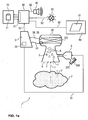
- FIG. 1a For example, an arrangement 1 for measuring gas with an optical gas sensor 300 is shown.
- the optical gas sensor 300 is referred to as a cuvette having one therein FIG. 1 a formed for reasons of clarity of the drawing not shown in more detail in detail -Multireflexionszelle.
- a radiation source and a detector element are arranged as sensory-metrological arrangement.
- light is radiated from the radiation source to an opposite wall, as well as lateral walls, reflected from there and detected by the detector element after multiple reflection.
- the presence of a test gas to be measured alters the absorption properties for the radiated light in the infrared wavelength range. This can be detected as a measuring effect of an attenuated signal on the detector element.
- a test gas to be measured for example methane, ethane, butane, propane alters the absorption properties for the radiated light in the infrared wavelength range. This can be detected as a measuring effect of an attenuated signal on the detector element.
- the measuring effect of damping the radiated IR light by certain gases, such as methane, ethane, butane, propane and other hydrocarbons results.
- the gas from a measuring environment 2 enters the optical gas sensor 300 via a gas inlet element 8, for example a semi-permeable or permeable membrane, a protective grid or a flameproof pane, into the measuring cuvette of the optical gas sensor 300.
- a gas inlet element 8 for example a semi-permeable or permeable membrane, a protective grid or
- an arrangement for gas measurement 1 in a device in which a plurality of gas sensors are arranged as gas sensor 30 it is technically customary and advantageous in many technical configurations to provide a plurality of gas inlet elements 8 arranged in series one behind the other. That's the way it is conceivable that of the measuring environment 2 two from downstream a first gas inlet element acts as flame protection or dust protection, then a second element prevents access of moisture and a third element 8 in the actual gas sensor, for example the optical gas sensor 300 or a catalytic 301 ( Fig. 1b ) or an electrochemical gas sensor 302 ( Fig. 1 c) or a semiconductor gas sensor 303 (FIG. Fig. 1 d) protects.
- the arrangement of the unit for excgasdostechnik 9 can be done both downstream of the measurement from between the first and second gas inlet element, between the second and third gas inlet element 8 or between the third gas inlet element 8 and the gas sensor 30, 300.
- These embodiments with a plurality of gas inlet elements and possible, suitable positions of the arrangement of the unit for excgasdostechnik 9 are for reasons of clarity in this FIG. 1 a in the arrangement for gas measurement 1 not shown.
- these design possibilities are within the meaning of the present invention as arrangements of the unit for excgasdostechnik 9 to the gas sensor 30 with - includes.
- Such a gas inlet 7 takes place from a measuring environment 2 towards the optical gas sensor 300.
- a unit for educable test substance supply 305 for example, from a tank 305 with a stock amount 306 a liquid fürstoffmenge 5 dosed.
- This liquid-injected test substance quantity 5 evaporates, atomizes or vaporizes in the gas sensor 300 to form a gaseous test substance quantity 6, which is then located in the optical gas sensor 300 for measurement.
- the unit for educagasdostechnik 9 is controlled by a control line 91 of a control unit 3 such that at predetermined times t 1, a predetermined amount of liquid fürstoffmengen 5 downstream of the gas inlet element 8 is metered into the optical gas sensor 300.
- the unit for educagasdostechnik 9 is designed as a piezo-metering.
- Such a piezo-dosing element is designed in combination with the test substance supply 305, with a single activation by means of a control signal 91 '(FIG. FIGS. 2, 3 ) to dose a precisely defined amount of test substance, without that a deactivation of the piezo-dosing element, for example by a further control signal 91 "( FIGS.
- the control unit 3 receives measurement signals 35, 38 from the optical gas sensor 300, or from the detector element in the optical gas sensor 300. Furthermore, the control unit 3 controls the infrared optical radiator in the optical gas sensor 300 by means of a control line 33.
- the measurement signal 35 as well as a measurement signal curve 38 based on the measurement signal 35 are transferred from the control unit 3 to an output unit 80 by means of a data or signal line 92 ,
- the output unit 80 is designed to control by means of signal and data line 92 an acoustic alarm, such as a horn 40, or optical alarm, such as a lamp 50.
- the output unit 80 is designed by means of an interface 81 to pass on signal and data lines 92, as well as control lines 91, data, evaluation results, sensor signals, data signals or processed measurement signals 35, 38 to an evaluation system 70.
- a database 71 is preferably arranged, which can log states and results of inspections of the gas measurement arrangement 1.
- a control and display unit (user interface) 60 is connected via a signal and data line 92.
- the operating and display unit 60 has a screen 61, on which error messages and instructions to a user, as well as measurement signals or measured values can be displayed.
- the control unit 3 and the test gas metering unit 9 cooperate, in conjunction with a data memory 32 arranged in the control unit 3 or a data memory 32 assigned to the control unit 3, in a method for checking the arrangement of the gas metering 1, as in FIG FIG. 2 and 3 is explained in more detail.
- the reaction of the optical gas sensor 300 is used to a dosage of a liquid fürstoffmenge 5 with evaporation of the liquid fürstoffmenge 5 in a gaseous fürstoffmenge 6 in the optical gas sensor 300 out to check, in which time this metered fürstoffmenge 5 via the gas inlet element is again diffused out of the optical gas sensor 300.
- a procedure for checking how accurate FIG. 3 can be seen performed.
- Timing is determined whether the metered amount 5, 6 after a certain time escaped from the optical gas sensor 300, or not. If, after a predetermined time, this metered-in quantity of test substance 5, 6 has not escaped from the optical gas sensor 300, then it can be inferred by the control unit 3 or determined that a faulty situation exists at the gas inlet element 8.
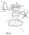
- the Figure 1 b shows one opposite the FIG. 1 a modified arrangement for gas measurement 1 '.
- a catalytic gas sensor 301 is shown instead of the optical gas sensor having an infrared multi-reflection cell 300.
- a catalytic gas sensor 301 is similar to FIG. 1a to the optical gas sensor 300 is connected to a control unit 3 and a test gas metering unit 9.
- Same elements in the FIGS. 1 a and 1 b are in the FIGS. 1 a and 1 b denoted by the same reference numerals.
- control unit 3 The description of the functionality and interaction of the control unit 3 with the test gas metering unit 9 is as to FIG. 1 a executed, also on the functionality of the interaction of control unit 3 and catalytic gas sensor 301 with inclusion of the unit for kaugasdostechnik 9 for checking the gas inlet element 8 transferable.
- FIG. 1 a shown elements output unit 80, evaluation system 70 and control and display unit 60 with the corresponding further elements, as well as connected to these elements data lines 92, and control lines 91 are in the Figure 1 b not shown in detail with.
- the control lines 91 and data lines 92 are only schematically indicated schematically in this arrangement for gas measurement 1 '.
- This effect is to be taken into account when checking the arrangement for gas measurement 1 ', or checking the gas inlet element 8 by means of the metered or diffused test substance quantities 5, 6 and the gas quantities that have escaped again after a certain time. This is in the FIG. 2 and the associated description explained in more detail.
- FIGS. 1 a, 1b and 1c are denoted by the same reference numerals in FIGS Figures 1 a, 1b and 1 c designated.
- FIG. 1 a with the arrangement for gas measurement 1 results in this arrangement for gas measurement 1 "in this Figure 1 c the aspect that another gas sensor 30, configured as a sensor-metrological arrangement of a preferably liquid electrolyte and an array of electrodes in the electrochemical gas sensor 302 is arranged.
- a special gas for example ammonia
- an electrochemical reaction or chemical reaction takes place at the electrodes.
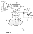
- FIG. 1d 1 shows an arrangement for measuring gas 1 '", which has a semiconductor gas sensor 303 as gas sensor 30.
- the to the FIGS. 1a . 1b and 1c made statements are also on the FIG. 1 d applicable.
- the arrangement for gas measurement 1 '" is comparable to FIGS. 1b and 1c executed in a simplified representation.
- Same elements in the Figures 1 a, b, 1 c and 1 d are in the Figures 1 a, b, 1 c and 1 d provided with the same reference numerals.
- the test gas metering unit 9 is shown as a combination of a test stock supply 305 with a valve 304.
- This valve 304 is actuated by the control unit 3 via control line 91.
- a stock 306 included in the test material supply 305 is similar to that in the Figures 1 a, 1b, 1c previously described, a stock 306 included. Preferably, it is in this Figure 1d at the storage amount 306 to a liquid gas, which is contained under pressure in theticianstoffvorrat 305.
- an amount of the supply amount 306 may reach the semiconductor gas sensor 303 from the sample stock supply 305.
- an amount of the supply quantity 306 as liquid test substance quantity 305 or already evaporated test substance quantity 6 reaches the semiconductor gas sensor 303.
- the transition from the liquid phase of the test substance quantity 5 to the gaseous phase of the test substance quantity 6 can be effected directly by pressure Relaxation upon opening of the valve 304, as well as in an impact or impact of liquid fürstoffmengen 5 carried on walls of the semiconductor gas sensor 303.
- the interaction of the control unit 3 with the unit for strigdostechnik 9 or valve 304 and educastoffvorrat 305 is in the description to FIG. 2 , as well as in the illustrated sequence FIG. 3 and the associated description of the process FIG. 3 explained in detail.
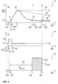
- FIG. 2 shows a typical course of a measurement signal of a gas measuring arrangement with a gas sensor during a test with a tester.
- Three diagrams 21, 22, 23 are shown, each representing a time course t 400 synchronized with each other.
- a measurement signal course 38, 38 'and 38 is represented as a time characteristic of a measurement signal S 35.
- the measurement signal S 35 is scaled to the ordinate the signal values are plotted, in which the measuring signal 38 reaches a value of 10% of the measuring signal amplitude S 35 of 100%, these points being marked in the course 38 with A, or B, respectively.
- the percentages shown 10%, 90%, 100% are advantageous for illustrating and clarifying the signal behavior of gas sensors, since temporal and dynamic properties of gas sensors can be described in this way standardized and comparable.
- the so-called t 10-90 rise time is suitable and is used to characterize a signal rise to an increase in gas concentration to 100% of the maximum range of measurement.
- the so-called t 10-90 rise time is often referred to as sensor response time.
- the t 10-90 rise time corresponds to the time during which the measurement signals, in a signal rise phase, have values in a value range between 10% and 90% of the final value (100%) of the signal due to the gas concentration change. For a characterization of a signal drop to a reduction or reduction of a gas concentration to 10% of the measuring range, this results in the so-called t 90-10 - decay time in a comparable manner.
- the t 90-10 fall time corresponds to the time during which the measurement signals, in a signal drop phase, have values in a value range between 90% and 10%.
- control signal 91 is output by the control unit 3 (FIG. FIGS. 1a, 1b, 1c and 1d, 3 ) generated.
- the third diagram 23 shows a section from the time course t 400.
- This section from the time course t 400 particularly important points in time are highlighted, which are used for checking the arrangement for gas measurement 1, 1 ', 1 ", 1'" (FIG. FIGS. 1a . 1b . 1c and 1d ) are essential.
- the time course t 400 of the essential times in the three diagrams 21, 22, 23 will now be described beginning with a time t 0 410.
- the same designated time points in the three diagrams 21, 22, 23 are mutually temporally synchronous with each other.
- the time course t 400 begins with a time t 0 410, in which the arrangement for gas measurement 1, 1 ', 1 ", 1'” ( FIGS. 1a . 1b . 1c and 1d ) Ambient air from the measuring environment 2 ( FIGS. 1a . 1b . 1c and 1d ) detected.
- the measurement signal S 35 shows a basic signal at time t 0 410 that represents the absence of test gas or noxious gas.
- a switching signal 91 'to the unit for administratgasdostechnik 9 ( FIGS. 1a . 1b . 1c and 1d ) is sent to a quantity of test substance 5 ( FIGS. 1a . 1b . 1c and 1d ) to the gas sensor 300, 301, 302, 303 (FIG. FIGS. 1a . 1b . 1c and 1d ) as a liquid amount to dose or inject.
- the amount of test substance 5 FIGS. 1a . 1b .
- the measuring signal S 35 responds to the metering the quantity of test substance 6 ( FIGS. 1a . 1b . 1c and 1d ) with a signal rise.
- the signal increase corresponds to the actual change in the gas concentration, caused by the metered gaseous test substance quantity 6 (FIG. FIGS. 1a . 1b . 1c and 1d ).
- the measurement signal S 35 already has 10% of the output amplitude, and the further signal rise 38 reaches an amplitude value of 90% approximately at the time t 1" .
- the dosage of the amount of test substance 5 ( FIGS. 1a . 1b . 1c and 1d ) completed.
- the measuring signal S 35 decreases.
- the value drops below FIG. 2 the measurement signal S 35 has an amplitude of 10%.
- This amplitude value of 10% is entered as point B at a time t B 403 "over time 400.
- time t 4 404, or t C 404" with a corresponding value of the measurement signal, S 35, shown as point C on the curve 38 ', the measurement signal S 35 is again with a signal drop to the basic signal before the dosage of the amount of test substance 5, 6 ( FIGS. 1a . 1b . 1c and 1d ) by means of the control signal 91 ', 91 "arrived.
- the second diagram 22 shows the profile of the control signal 91 over the time course t 400.
- This time profile t 400 of the second diagram 22 is shown synchronously with the time profile t 400 of the first diagram 21.
- a control signal 91 ' is activated at a time t 1 401, which determines the dosage of the test substance quantity 5 (FIG. FIGS. 1a . 1b . 1c and 1d ) causes.
- the deactivation of the dosage of the test substance quantity 5 FIGS. 1a . 1b . 1c and 1d ) by means of the control signal 91 ".
- the third diagram 23 of this FIG. 2 shows in sections two highlighted periods 408 and 409 over time t 400. These two periods 408, 409 are for the verification of the arrangement for gas measurement 1, 1 ', 1 ", 1'" ( Figures 1a, 1 b, 1 c and 1 d ) relevant for classification over time t 400.
- the process time duration 408 is the time duration that occurs when an unimpeded inflow and outflow of gas from the measurement environment 2 (FIG. Figures 1a, 1 b, 1 c and 1 d ) through the gas inlet element 8 ( Figures 1a, 1 b, 1 c and 1 d ) to the gas sensor 30, 300, 301, 302, 303 (FIG.
- FIGS. 1a . 1b . 1c and 1d are respectively a time duration for inflow and outflow, beginning with the time t 1 ' , 401', during which after the metering the conversion, or evaporation or evaporation of the liquid test substance quantity 5 into the gaseous test substance quantity 6 (FIG. FIGS. 1a . 1b . 1c and 1d ) on the sensory-metrological arrangement ( FIGS. 1a . 1b . 1c and 1d ) comes into effect until the outflow of gaseous test substance 6 ( FIGS. 1a . 1b . 1c .
- FIGS. 1a . 1b . 1c . 1d and 3 Wind effects or pressure fluctuations in the measurement environment 2 ( FIGS. 1a . 1b . 1c . 1d and 3 ) are neglected in the first approach in the choice of a suitable process time.
- the time t 3 403 results with respect to the time 401 't 1' as a time duration of the sensor reaction after evaporation of the liquid metered amount of test substance 5 ( FIGS. 1a . 1b .
- the process time duration 408 thus corresponds to the time duration in which a quantity of test substance 5 metered in as a liquid quantity of test substance 5 and then converted to gaseous conversion after conversion (FIG. FIGS. 1a . 1b . 1c and 1d ) is effective on the sensory-metrological arrangement or is no longer effective.
- the duration 409 begins with the end of the above-described process time duration 408. It is shown in the diagrams 21, 23 that the duration of the inflow 7 (FIG. FIGS. 1a . 1b . 1c . 1d ) of gas from the measurement environment 2 ( FIGS. 1a . 1b . 1c . 1d ) and the subsequent duration of the outflow of gas back into the measuring environment 2 ( FIGS. 1a . 1b . 1c . 1d ) together as process time duration 408 corresponds to a sum of signal rise phase and signal fall phase.
- An alternative to determining the start of the time period 409 is possible, for example, by setting a twofold response time as a correspondence to the process time duration 408.
- a further alternative is made possible if, experimentally or by calculation, the respective diffusion times for inflow and outflow as well as their sum are based on the design of the gas inlet element 8 (FIG. FIGS. 1a . 1b . 1c and 1d ) in the arrangement for gas measurement 1, 1 ', 1 ", 1'" ( FIGS. 1a . 1b . 1c and 1d ) and the respectively associated material properties (number of gas inlet elements, pore size, area, diameter) are determined and stored accordingly as a process period 408.
- the points B and C are drawn at times t B 403 "and tc 404", wherein they are located purely coincidentally at the times t 3 403 and t 4 404.
- an undershooting of the 10% amplitude value can be given at any time in the expectation window 409. If this point B is located at 10% of the amplitude of the measurement signal S 35 in the expectation window 409 between the times t 3 and t 4 , then the control unit 3 (FIG. FIGS. 1a . 1b . 1c and 1d ) are evaluated and inferred that the check has been carried out with a result that the gas inlet element 8 (FIG. FIGS. 1a . 1b . 1c and 1d ) is sufficiently free without blockages or soiling.
- the measurement signal course 38 "shows a course, which is associated with a sensory-metrological arrangement with a catalytic gas sensor 301 or an electrochemical gas sensor 302, a decreasing measurement signal S 35, which includes both a catalytic gas sensor 301 and an electrochemical gas sensor 302
- the measuring signal S 35 drops after metering even if no gas from the gas sensor 30 (FIG. FIGS. 1a . 1b . 1c and 1d ) into the measuring environment 2 ( FIGS. 1a . 1b . 1c and 1d ) can escape, or can escape again.
- the course after 38 "thus shows a case in which a gas inlet element 8 (FIG. FIGS. 1a . 1b . 1c and 1d ) of a catalytic gas sensor 301 or an electrochemical gas sensor 302 to the measurement environment 2 (FIG. FIGS. 1a . 1b . 1c and 1d ) closed or prevented in gas exchange.
- the FIG. 3 1 shows a flow chart 1000 for a check of a gas measurement arrangement 1, 1 ', 1 ", 1'" (FIG. FIGS. 1a . 1b . 1c and 1d ) with a start 100 and an end 106 (stop).
- the sequence 1000 controls the sequence of five operating states 101, 102, 103, 104, 105 from the start 100 to the end 106.
- the control unit 3 uses to control the process 1000 time-measuring functions, which in this FIG. 3 are shown as the operating states 102, 102 ', 103 and 104 assigned timer 44.
- the control unit 3 acts via control signals, control lines 91, 91 ', 91 "and control lines 33 to the operating conditions 101, 102, 103, 104, 105, as well as on the fürán 9.
- the passage of the times by means of the timer 44 by the control unit 3 is controlled is symbolized by a synchronization signal 34.
- the normal measuring operation is carried out with the gas sensor 30 in a first step 101. Measured signals acquired during this process are evaluated and displayed. The necessary connections and elements are in this FIG. 3 not shown.
- a gas inlet 7 from a measuring environment 2 passes via a gas inlet element 8 into a gas sensor 30 and in the gas sensor 30 to a sensor-measuring arrangement.
- a second operating state 102 (test gas)
- the test gas source 9 is activated by the control unit 3 by means of a control line 33 in order to meter a quantity of test substance 5, 6 to the gas sensor 30.
- a timer 44 is activated by the control unit 3 by means of a control signal 91 'and thus a time t 1 401 is marked.
- the time t 1 is stored in a data memory 32 located in the control unit 3, so that it is available for the fifth operating state (case distinction) 105.
- the necessary for the transition of the liquid metered amount of test substance 5 in a gaseous test substance amount 6 evaporation time, as in FIG. 1a is described as a time t 1 ' 401' also deposited there.
- the second operating state 102 is followed by a further step 102 'as part of the second operating state 102, in which the control unit 3 sends a further control signal 91 "to the test gas source 9 in order to dose the quantity of test substance 5 at a time t 2 402
- the test gas source 9 as a piezo metering element
- the deactivation of the test gas source 9 can be dispensed with, since no deactivation signal 91 "is required in the second operating state 102 for the metering control of the piezo metering element is.
- the metering with a piezo-metering element can be provided to set a dosage of the amount of test substance by a sequence of drops. By specifying a predetermined number of pulses on the piezo-dosing a corresponding number of pulses with the number of drops is dosed as educastoffmenge.
- a measurement signal S 35, as well as a measurement signal curve 38 based on the metered quantity of test substance 5, 6 are detected by the gas sensor system 30.
- the measurement signal S 35, as well as the measurement signal waveform 38 are provided by means of a Messsignal glove 37 and a signal forwarding 36 the flow 1000, and thus the control unit 3.
- the detected measurement signal S 35 is compared with a first measured signal threshold 350.
- a further check of the measurement signal S 35 takes place at a predetermined time t 4 404 following the time t 3 403, in a manner similar to that described in the third operating state 103, with a comparison of the detected measurement signal S 35 with a second measured signal threshold 351.
- the values of the first measured signal threshold value 350 and of the second measured signal threshold value 351 are derived from a previously determined typical signal behavior of the sensor-metrological arrangement with metering of the test substance quantity 5, 6 with the test gas source 9 with unimpeded outflow into the measuring environment 2 through the gas inlet element 8.
- This is preferably already the case FIG. 2 mentioned response (rise time, eg t 10-90 - rise time, fall time, eg t 90-10 - fall time), the course of the signal amplitude 35, 38 (zero signal, maximum signal amplitude) at an unimpeded inflow 7 through the gas inlet element 8 to the metrological arrangement and unhindered outflow into the measuring environment 2 through the gas inlet element 8 with a.
- a value with a lower signal amplitude than the value of the first measured signal threshold value 351 is selected for the second measured signal threshold value 351, since an unimpeded outflow of the metered quantity of test substance 5, 6 from the gas sensor 30 through the gas inlet element 8 into the measuring environment 2 in the course of the measuring signal 38 shows a constellation with a signal drop 38 ', 38 "(FIG. FIG. 2 ) during the expectation window 409 ( FIG. 2 ).
- the results of the comparisons of the measuring signal 35 with the measured signal threshold values 350, 351 are evaluated as to whether the measuring signal 35 in the course 38 lies below one of the threshold values 350, 351. If the comparison yields the result that the measuring signal 35 has fallen below the threshold values 350, 351, the system branches into a first state of the gas sensor system 200, from which the measuring mode 101 is continued. In this case, the checking of the gas sensor 30 by means of the metered quantity of test substance 5, 6 is completed with the positive result that the gas inlet element 8 allows an unimpeded inflow 7, that is, that the gas inlet element 8 is free of blockages.
Landscapes
- Chemical & Material Sciences (AREA)
- Health & Medical Sciences (AREA)
- Life Sciences & Earth Sciences (AREA)
- Engineering & Computer Science (AREA)
- Physics & Mathematics (AREA)
- General Physics & Mathematics (AREA)
- Pathology (AREA)
- Analytical Chemistry (AREA)
- Biochemistry (AREA)
- General Health & Medical Sciences (AREA)
- Immunology (AREA)
- Combustion & Propulsion (AREA)
- Food Science & Technology (AREA)
- Medicinal Chemistry (AREA)
- Chemical Kinetics & Catalysis (AREA)
- Spectroscopy & Molecular Physics (AREA)
- Molecular Biology (AREA)
- Electrochemistry (AREA)
- Investigating Or Analyzing Materials By The Use Of Electric Means (AREA)
- Investigating Or Analyzing Materials By The Use Of Fluid Adsorption Or Reactions (AREA)
Applications Claiming Priority (1)
| Application Number | Priority Date | Filing Date | Title |
|---|---|---|---|
| DE102016003283.9A DE102016003283B4 (de) | 2016-03-18 | 2016-03-18 | Gasmessvorrichtung mit einer Prüfvorrichtung zur Überprüfung eines Gassensors |
Publications (1)
| Publication Number | Publication Date |
|---|---|
| EP3220141A1 true EP3220141A1 (fr) | 2017-09-20 |
Family
ID=58266335
Family Applications (1)
| Application Number | Title | Priority Date | Filing Date |
|---|---|---|---|
| EP17000356.0A Withdrawn EP3220141A1 (fr) | 2016-03-18 | 2017-03-07 | Procédé de vérification d'un capteur de gaz et dispositif de mesure de gaz, détecteur de gaz comprenant un dispositif de vérification d'un capteur de gaz |
Country Status (4)
| Country | Link |
|---|---|
| US (1) | US10132786B2 (fr) |
| EP (1) | EP3220141A1 (fr) |
| CN (1) | CN107202771B (fr) |
| DE (1) | DE102016003283B4 (fr) |
Families Citing this family (16)
| Publication number | Priority date | Publication date | Assignee | Title |
|---|---|---|---|---|
| WO2016145119A1 (fr) * | 2015-03-09 | 2016-09-15 | Spectrasensors, Inc. | Analyseur spectroscopique à sécurité intrinsèque |
| DE102016003284B4 (de) * | 2016-03-18 | 2022-05-19 | Dräger Safety AG & Co. KGaA | Gasmessvorrichtung mit einer Prüfvorrichtung zur Überprüfung eines Gassensors |
| US10663440B2 (en) | 2016-09-09 | 2020-05-26 | Consumer Safety Technology, Llc | Secure data handling in a breath alcohol calibration station |
| US10877008B2 (en) | 2016-09-09 | 2020-12-29 | Consumer Safety Technology, Llc | Reference gas management in a breath alcohol calibration station |
| US10900942B2 (en) * | 2018-10-15 | 2021-01-26 | Honeywell International Inc. | Device and method for detecting restrictions in gas access to a gas sensor |
| EP3942304A4 (fr) * | 2019-03-22 | 2022-11-30 | Blackline Safety Corp. | Appareil et procédés de test de capteurs de gaz |
| US12135318B2 (en) | 2019-04-16 | 2024-11-05 | Measured Air Performance, LLC | Field calibration for a multipoint air sampling system |
| DE102019002963A1 (de) * | 2019-04-25 | 2020-10-29 | Drägerwerk AG & Co. KGaA | Vorrichtung und Verfahren zur Überwachung einer Schall- und Gasexpositon |
| CN110057870B (zh) * | 2019-05-06 | 2022-07-08 | 宁波大学 | 基于stm32的智能液态蒸发式voc气体测试表征仪 |
| US11190949B2 (en) * | 2019-11-22 | 2021-11-30 | Charter Communications Operating, Llc | Methods and apparatus for monitoring contested spectrum and/or responding to the detection of an incumbent user |
| DE102020101163A1 (de) | 2020-01-20 | 2021-07-22 | Vaillant Gmbh | Sensorverschaltung |
| DE102020115804A1 (de) * | 2020-06-16 | 2021-12-16 | Dräger Safety AG & Co. KGaA | Elektrochemische Sensoranordnung, Atemalkoholmessgerät und Verfahren zum Bestimmen einer Vitalität von Elektroden eines elektrochemischen Sensors |
| DE102020132771A1 (de) * | 2020-12-09 | 2022-06-09 | Dräger Safety AG & Co. KGaA | Gasmessgerät |
| US12436137B2 (en) * | 2021-10-25 | 2025-10-07 | Carrier Corporation | Systems and methods for membrane blockage detection in gas detectors |
| CN114113480B (zh) * | 2021-11-23 | 2024-03-26 | 青岛崂应海纳光电环保集团有限公司 | 一种多气体传感器响应时间自动测试装置和方法 |
| CN115598299B (zh) * | 2022-09-30 | 2023-09-12 | 西安交通大学 | 一种基于大气扩散模型的环境影响评估方法及系统 |
Citations (19)
| Publication number | Priority date | Publication date | Assignee | Title |
|---|---|---|---|---|
| US433828A (en) | 1890-08-05 | Egbert edward sherlock and manfred freeman | ||
| CH624488A5 (fr) | 1976-05-15 | 1981-07-31 | Bayer Ag | |
| US4854155A (en) | 1988-10-19 | 1989-08-08 | Mine Safety Appliances Company | Combustible gas detector having catalytic sensor stabilizing network |
| US5565075A (en) | 1995-06-06 | 1996-10-15 | Mine Safety Appliances Company | Electrochemical gas sensor for the detection of nitric oxide |
| WO1999017110A1 (fr) | 1997-10-01 | 1999-04-08 | Analytical Technology, Inc. | Detecteur de gaz combustible a generateur d'hydrogene integre |
| US6182497B1 (en) | 1999-08-20 | 2001-02-06 | Neodym Systems Inc | Gas detection system and method |
| GB2356708A (en) | 1999-11-27 | 2001-05-30 | Central Research Lab Ltd | Sensor system with self-test facility |
| WO2002091326A1 (fr) * | 2001-05-09 | 2002-11-14 | Tormaxx Gmbh | Generateur de gaz de fumee mobile et procede de testage d'un indicateur de gaz de fumee |
| EP1281957A1 (fr) * | 2001-07-30 | 2003-02-05 | Siemens Building Technologies AG | Avertisseur de gaz combustible avec dispositif d'autotest |
| US20050247878A1 (en) | 2004-02-11 | 2005-11-10 | Dieter Baschant | Infrared gas sensor |
| DE102006045055B3 (de) * | 2006-09-21 | 2008-02-21 | Micronas Gmbh | Gasmeldeeinrichtung und Verfahren zum Überprüfen einer solchen |
| US7406854B2 (en) | 2005-01-22 | 2008-08-05 | Dräger Safety AG & Co. KGaA | Gas sensor |
| DE202006020536U1 (de) | 2006-09-29 | 2008-11-13 | Dräger Safety AG & Co. KGaA | Elektrochemischer Gasgenerator für brennbare Gase |
| US7645367B2 (en) | 2005-04-15 | 2010-01-12 | Dräger Safety AG & Co. KGaA | Gas-measuring system with gas sensor and gas generator |
| DE102009052957A1 (de) | 2009-11-12 | 2011-06-09 | Dräger Safety AG & Co. KGaA | Gassensor mit Prüfgasgenerator |
| US20130019233A1 (en) | 2011-07-12 | 2013-01-17 | Apple Inc. | System and method for linking pre-installed software to a user account on an online store |
| US20130192332A1 (en) * | 2011-10-14 | 2013-08-01 | Towner B. Scheffler | Sensor interrogation |
| EP2639583A1 (fr) * | 2012-03-12 | 2013-09-18 | Mettler-Toledo AG | Contrôle du fonctionnement de capteurs de gaz de conductivité thermique |
| EP2887062A2 (fr) * | 2013-12-20 | 2015-06-24 | Honeywell International Inc. | Détecteurs de gaz à commande magnétique |
Family Cites Families (11)
| Publication number | Priority date | Publication date | Assignee | Title |
|---|---|---|---|---|
| DE3019387C2 (de) | 1980-05-21 | 1986-01-23 | Siemens AG, 1000 Berlin und 8000 München | Dünnschicht-Halbleiter-Gassensor mit einem in den Sensoraufbau integrierten Heizelement |
| DE3821831A1 (de) * | 1988-06-29 | 1990-01-04 | Draegerwerk Ag | Automatisierte vorrichtung und verfahren zum nachweis gasfoermiger komponenten in luft mittels eines kolorimetrischen pruefroehrchens |
| US5608384A (en) * | 1992-10-23 | 1997-03-04 | Sentech Corporation | Method and apparatus for monitoring for the presence of a gas |
| CN100437104C (zh) * | 2005-05-18 | 2008-11-26 | 深圳市奥特迅传感技术有限公司 | 气体传感器及由其制成的气体检测器 |
| US7661290B2 (en) * | 2007-07-20 | 2010-02-16 | Honeywell International Inc. | Gas sensor test and calibration system |
| DE202011102765U1 (de) * | 2011-07-02 | 2012-08-02 | Dräger Safety AG & Co. KGaA | Vorrichtung mit einer Messanordnung zur infrarot-optischen Messung von Gasen und Gasgemischen mit Kompensation von Umgebungseinflüssen |
| DE102012008274A1 (de) * | 2011-11-28 | 2013-05-29 | Dräger Safety AG & Co. KGaA | Gasbeaufschlagungs-Vorrichtung für Gasmessgeräte, Verfahren zum Prüfen von Gas-Messgeräten sowie Kalibrierungsmessgerät zum Prüfen und Kalibrieren von Gasmessgeräten |
| DE102012007016B3 (de) * | 2012-04-05 | 2013-10-10 | Dräger Safety AG & Co. KGaA | Optischer Gassensor |
| CN102928485B (zh) * | 2012-08-14 | 2014-08-20 | 无锡市尚沃医疗电子股份有限公司 | 自标定电化学气体传感器 |
| US9546950B2 (en) * | 2014-09-26 | 2017-01-17 | Rosemount Analytical Inc. | Optical gas sensing apparatus with explosion-proof enclosure |
| DE102015015152B4 (de) * | 2015-11-25 | 2017-07-20 | Dräger Safety AG & Co. KGaA | Verfahren zur Überprüfung eines Gassensors in einem Gasmesssystem |
-
2016
- 2016-03-18 DE DE102016003283.9A patent/DE102016003283B4/de active Active
-
2017
- 2017-03-07 EP EP17000356.0A patent/EP3220141A1/fr not_active Withdrawn
- 2017-03-16 US US15/460,680 patent/US10132786B2/en active Active
- 2017-03-17 CN CN201710160338.7A patent/CN107202771B/zh active Active
Patent Citations (19)
| Publication number | Priority date | Publication date | Assignee | Title |
|---|---|---|---|---|
| US433828A (en) | 1890-08-05 | Egbert edward sherlock and manfred freeman | ||
| CH624488A5 (fr) | 1976-05-15 | 1981-07-31 | Bayer Ag | |
| US4854155A (en) | 1988-10-19 | 1989-08-08 | Mine Safety Appliances Company | Combustible gas detector having catalytic sensor stabilizing network |
| US5565075A (en) | 1995-06-06 | 1996-10-15 | Mine Safety Appliances Company | Electrochemical gas sensor for the detection of nitric oxide |
| WO1999017110A1 (fr) | 1997-10-01 | 1999-04-08 | Analytical Technology, Inc. | Detecteur de gaz combustible a generateur d'hydrogene integre |
| US6182497B1 (en) | 1999-08-20 | 2001-02-06 | Neodym Systems Inc | Gas detection system and method |
| GB2356708A (en) | 1999-11-27 | 2001-05-30 | Central Research Lab Ltd | Sensor system with self-test facility |
| WO2002091326A1 (fr) * | 2001-05-09 | 2002-11-14 | Tormaxx Gmbh | Generateur de gaz de fumee mobile et procede de testage d'un indicateur de gaz de fumee |
| EP1281957A1 (fr) * | 2001-07-30 | 2003-02-05 | Siemens Building Technologies AG | Avertisseur de gaz combustible avec dispositif d'autotest |
| US20050247878A1 (en) | 2004-02-11 | 2005-11-10 | Dieter Baschant | Infrared gas sensor |
| US7406854B2 (en) | 2005-01-22 | 2008-08-05 | Dräger Safety AG & Co. KGaA | Gas sensor |
| US7645367B2 (en) | 2005-04-15 | 2010-01-12 | Dräger Safety AG & Co. KGaA | Gas-measuring system with gas sensor and gas generator |
| DE102006045055B3 (de) * | 2006-09-21 | 2008-02-21 | Micronas Gmbh | Gasmeldeeinrichtung und Verfahren zum Überprüfen einer solchen |
| DE202006020536U1 (de) | 2006-09-29 | 2008-11-13 | Dräger Safety AG & Co. KGaA | Elektrochemischer Gasgenerator für brennbare Gase |
| DE102009052957A1 (de) | 2009-11-12 | 2011-06-09 | Dräger Safety AG & Co. KGaA | Gassensor mit Prüfgasgenerator |
| US20130019233A1 (en) | 2011-07-12 | 2013-01-17 | Apple Inc. | System and method for linking pre-installed software to a user account on an online store |
| US20130192332A1 (en) * | 2011-10-14 | 2013-08-01 | Towner B. Scheffler | Sensor interrogation |
| EP2639583A1 (fr) * | 2012-03-12 | 2013-09-18 | Mettler-Toledo AG | Contrôle du fonctionnement de capteurs de gaz de conductivité thermique |
| EP2887062A2 (fr) * | 2013-12-20 | 2015-06-24 | Honeywell International Inc. | Détecteurs de gaz à commande magnétique |
Also Published As
| Publication number | Publication date |
|---|---|
| US10132786B2 (en) | 2018-11-20 |
| DE102016003283B4 (de) | 2022-05-19 |
| DE102016003283A1 (de) | 2017-09-21 |
| CN107202771A (zh) | 2017-09-26 |
| CN107202771B (zh) | 2021-03-12 |
| US20170269044A1 (en) | 2017-09-21 |
Similar Documents
| Publication | Publication Date | Title |
|---|---|---|
| DE102016003283B4 (de) | Gasmessvorrichtung mit einer Prüfvorrichtung zur Überprüfung eines Gassensors | |
| DE102016003284B4 (de) | Gasmessvorrichtung mit einer Prüfvorrichtung zur Überprüfung eines Gassensors | |
| DE102015015152B4 (de) | Verfahren zur Überprüfung eines Gassensors in einem Gasmesssystem | |
| DE69708688T2 (de) | Überwachung und steuerung von sterilisierungsverfahren mit halbleitersensormodulen | |
| DE102016100403B4 (de) | NOx-SENSOR-DIAGNOSESYSTEM UND -VERFAHREN | |
| EP1412759B1 (fr) | Procede et dispositif d'evaluation d'un processus de dosage de liquide | |
| DE69912239T2 (de) | Verfahren zur erkennung einer verstopfung in einem druckmessenden durchflussre- gler und ein für diesen zweck verwendeter sensor | |
| EP2539681A1 (fr) | Dispositif pour mesurer la concentration en particules dans les gaz d'échappement de véhicules automobiles | |
| EP3475686B1 (fr) | Méthode et appareil pour surveillance des fluids gazeux | |
| DE102015015153B4 (de) | Verfahren zur Überprüfung einer Pumpeneinrichtung in einem Gasmessystem | |
| EP1903528A1 (fr) | Dispositif de mélange de gaz et procédé destiné à sa surveillance | |
| DE19708052C2 (de) | Vorrichtung zum automatischen Kalibrieren von Gassensoren | |
| DE4226082A1 (de) | Verfahren und Vorrichtung zur Überwachung von Sensoren | |
| EP2411801A1 (fr) | Procédé permettant de déterminer un nombre de gouttes | |
| EP1038160B1 (fr) | Procede et dispositif pour la mesure autocompensee du debit volumetrique de gaz | |
| EP4043873A1 (fr) | Dispositif de détection de gaz et procédé de détection de gaz au moyen d'un détecteur et d'un modulateur | |
| DE102015003745B4 (de) | Mobile Prüfvorrichting, Gasmessgerät und System zum Prüfen eines Gasmessgeräts | |
| EP3173784B1 (fr) | Compteur de gaz avec unité de production de gaz de controle | |
| EP2711907B1 (fr) | Avertisseur, dispositif de test et procédé de contrôle d'un avertisseur | |
| EP0596231A1 (fr) | Méthode et appareil pour mesurer la turbidité en mulieu aqueux | |
| DE10139993B4 (de) | Melder, Testvorrichtung zum Prüfen eines Melders und Verfahren zum Betreiben eines Melders | |
| DE10107260A1 (de) | Verfahren und Einrichtung zur Überwachung unterirdischer Anlagen | |
| DE102024128713B3 (de) | Anordnung zum fehlersicheren Detektieren eines Gases in einem Raumbereich und Verwendung derselben als Leckagesensor | |
| EP1768074A1 (fr) | Détection prompte d'incendies | |
| EP4478031A1 (fr) | Procédé et dispositif de contrôle d'un appareil de détection de gaz |
Legal Events
| Date | Code | Title | Description |
|---|---|---|---|
| PUAI | Public reference made under article 153(3) epc to a published international application that has entered the european phase |
Free format text: ORIGINAL CODE: 0009012 |
|
| AK | Designated contracting states |
Kind code of ref document: A1 Designated state(s): AL AT BE BG CH CY CZ DE DK EE ES FI FR GB GR HR HU IE IS IT LI LT LU LV MC MK MT NL NO PL PT RO RS SE SI SK SM TR |
|
| AX | Request for extension of the european patent |
Extension state: BA ME |
|
| 17P | Request for examination filed |
Effective date: 20180214 |
|
| RBV | Designated contracting states (corrected) |
Designated state(s): AL AT BE BG CH CY CZ DE DK EE ES FI FR GB GR HR HU IE IS IT LI LT LU LV MC MK MT NL NO PL PT RO RS SE SI SK SM TR |
|
| 17Q | First examination report despatched |
Effective date: 20181127 |
|
| STAA | Information on the status of an ep patent application or granted ep patent |
Free format text: STATUS: THE APPLICATION HAS BEEN WITHDRAWN |
|
| 18W | Application withdrawn |
Effective date: 20190115 |