EP3220160B1 - Aeronef equipe d'un lecteur laser - Google Patents
Aeronef equipe d'un lecteur laser Download PDFInfo
- Publication number
- EP3220160B1 EP3220160B1 EP16160065.5A EP16160065A EP3220160B1 EP 3220160 B1 EP3220160 B1 EP 3220160B1 EP 16160065 A EP16160065 A EP 16160065A EP 3220160 B1 EP3220160 B1 EP 3220160B1
- Authority
- EP
- European Patent Office
- Prior art keywords
- mirror
- aircraft
- flight
- laser scanner
- laser
- Prior art date
- Legal status (The legal status is an assumption and is not a legal conclusion. Google has not performed a legal analysis and makes no representation as to the accuracy of the status listed.)
- Active
Links
Images


Classifications
-
- G—PHYSICS
- G01—MEASURING; TESTING
- G01S—RADIO DIRECTION-FINDING; RADIO NAVIGATION; DETERMINING DISTANCE OR VELOCITY BY USE OF RADIO WAVES; LOCATING OR PRESENCE-DETECTING BY USE OF THE REFLECTION OR RERADIATION OF RADIO WAVES; ANALOGOUS ARRANGEMENTS USING OTHER WAVES
- G01S7/00—Details of systems according to groups G01S13/00, G01S15/00, G01S17/00
- G01S7/48—Details of systems according to groups G01S13/00, G01S15/00, G01S17/00 of systems according to group G01S17/00
- G01S7/4802—Details of systems according to groups G01S13/00, G01S15/00, G01S17/00 of systems according to group G01S17/00 using analysis of echo signal for target characterisation; Target signature; Target cross-section
-
- G—PHYSICS
- G01—MEASURING; TESTING
- G01S—RADIO DIRECTION-FINDING; RADIO NAVIGATION; DETERMINING DISTANCE OR VELOCITY BY USE OF RADIO WAVES; LOCATING OR PRESENCE-DETECTING BY USE OF THE REFLECTION OR RERADIATION OF RADIO WAVES; ANALOGOUS ARRANGEMENTS USING OTHER WAVES
- G01S17/00—Systems using the reflection or reradiation of electromagnetic waves other than radio waves, e.g. lidar systems
- G01S17/02—Systems using the reflection of electromagnetic waves other than radio waves
- G01S17/06—Systems determining position data of a target
- G01S17/42—Simultaneous measurement of distance and other co-ordinates
-
- G—PHYSICS
- G01—MEASURING; TESTING
- G01S—RADIO DIRECTION-FINDING; RADIO NAVIGATION; DETERMINING DISTANCE OR VELOCITY BY USE OF RADIO WAVES; LOCATING OR PRESENCE-DETECTING BY USE OF THE REFLECTION OR RERADIATION OF RADIO WAVES; ANALOGOUS ARRANGEMENTS USING OTHER WAVES
- G01S17/00—Systems using the reflection or reradiation of electromagnetic waves other than radio waves, e.g. lidar systems
- G01S17/88—Lidar systems specially adapted for specific applications
- G01S17/89—Lidar systems specially adapted for specific applications for mapping or imaging
-
- G—PHYSICS
- G01—MEASURING; TESTING
- G01S—RADIO DIRECTION-FINDING; RADIO NAVIGATION; DETERMINING DISTANCE OR VELOCITY BY USE OF RADIO WAVES; LOCATING OR PRESENCE-DETECTING BY USE OF THE REFLECTION OR RERADIATION OF RADIO WAVES; ANALOGOUS ARRANGEMENTS USING OTHER WAVES
- G01S17/00—Systems using the reflection or reradiation of electromagnetic waves other than radio waves, e.g. lidar systems
- G01S17/88—Lidar systems specially adapted for specific applications
- G01S17/93—Lidar systems specially adapted for specific applications for anti-collision purposes
- G01S17/933—Lidar systems specially adapted for specific applications for anti-collision purposes of aircraft or spacecraft
-
- G—PHYSICS
- G01—MEASURING; TESTING
- G01S—RADIO DIRECTION-FINDING; RADIO NAVIGATION; DETERMINING DISTANCE OR VELOCITY BY USE OF RADIO WAVES; LOCATING OR PRESENCE-DETECTING BY USE OF THE REFLECTION OR RERADIATION OF RADIO WAVES; ANALOGOUS ARRANGEMENTS USING OTHER WAVES
- G01S7/00—Details of systems according to groups G01S13/00, G01S15/00, G01S17/00
- G01S7/48—Details of systems according to groups G01S13/00, G01S15/00, G01S17/00 of systems according to group G01S17/00
- G01S7/481—Constructional features, e.g. arrangements of optical elements
- G01S7/4817—Constructional features, e.g. arrangements of optical elements relating to scanning
Definitions
- the present invention relates to an aircraft with a laser scanner for measuring an environment according to the preamble of claim 1.
- laser scanners to measure the flown environment by means of the laser scanner emitted laser beams based on their reflections on the environment.
- a particularly suitable type of laser scanner emits laser beams in the form of a scanning disk in order to measure the environment in a line across the direction of flight. The movement of the aircraft and the repetitive linear scanning of the environment allow a 3D model of the environment to be obtained.
- Such laser scanners are known, for example, under the trademark VUX® from Riegl Laser Measurement Systems GmbH in Horn, Austria.
- collision warning systems for example on radio or radar base to increase flight safety.
- collision warning systems always mean additional weight and thus increased fuel and energy requirements, which is special is prohibitive for use on small, unmanned aerial vehicles.
- the invention has for its object to provide an aircraft with a laser scanner for surveying an environment that provides increased safety in flight without significant increase in weight, so it is particularly suitable for a design as a highly mobile, lightweight, unmanned surveying aircraft.
- an aircraft with a laser scanner for measuring an environment, wherein the laser scanner is designed to emit laser beams with different transmission angles about an axis, wherein a mirror is arranged in the beam path of the laser beams of a predetermined subarea of transmission angles, wherein the laser scanner is designed to determine the transit times of laser beams emitted within said subarea as well as of laser beams emitted outside of said subarea by means of their reflections on the surroundings, which aircraft is distinguished by the fact that the mirror deflects the laser beams emitted in said subarea into a plane which is parallel to a predetermined horizontal direction of flight, wherein said portion includes those laser beams that would be reflected without mirror from the aircraft.
- the aircraft according to the invention with integrated laser scanner which both measures the environment and acts as a collision warning system, is particularly lightweight and space-saving due to the simultaneous use of its components for several purposes.
- a part of the scan fan or scanning disk generated by the laser scanner for creating the environment model can be "decoupled” and used as (partial) scan compartments for collision warning.
- the decoupled (partial) scan fan may, for example, lie in a plane parallel to the direction of flight of the aircraft is to detect objects that are in the trajectory of the aircraft.
- the mirror can be located, for example, in a shading area of the scanning fan or the scanning disk between the laser scanner and the aircraft, so that laser beams, which could not be used anyway for laser measuring the environment, since they would be reflected by the aircraft, can be used for collision detection. Because the mirror deflects the laser beams emitted in said subarea into a plane which is parallel to the desired direction of flight, the laser scanner can "look ahead" in the subarea for the purpose of collision avoidance.
- the laser scanner could generate the laser beams in different transmission angles with different laser sources.
- the laser scanner is a 360 ° -2D laser scanner.
- a "2D laser scanner” is understood to mean a laser scanner whose laser scanning beam moves only within a single scanning plane, ie emits a single beam fan onto the surroundings, in order to produce a 2D profile of the surroundings from the reflection, which the Section line of the scanning plane corresponds to the environmental relief.
- a "360 ° -2D laser scanner” is understood to mean a 2D laser scanner whose laser scanning beam rotates in the scanning plane by a full 360 ° to produce a full (360 °) scanning disk.
- the aircraft of the invention may be equipped with a detection device which outputs a warning signal when the travel time of at least one laser beam emitted within said subarea falls below a threshold value.
- the warning signal can be of an optical and / or acoustic nature and can be delivered directly to the aircraft for warning the pilot or persons and animals in the vicinity of the aircraft, or in the case of an unmanned aerial vehicle via a radio link to a remote control for a person on the ground that controls the aircraft.
- the detection device can also cause a change in the speed and / or direction of the aircraft when the travel time of at least one laser beam emitted within said subarea falls below a threshold value.
- a threshold value e.g. an automatic speed reduction, a "stop" of the aircraft in the air or an automatic avoidance maneuver for collision avoidance with the detected object or the environment are effected.
- the detection device can also be designed to output the warning signal or to cause the speed and / or direction change of the aircraft if an average value of transit times of a plurality of laser beams emitted within the subarea falls below a threshold value.
- the said plurality of laser beams can either originate from the same period of the laser scanner, ie locally "next to each other" to take into account only objects of a certain size, and / or have been emitted in several periods of the laser scanner at the same angle be, ie temporally "behind each other" to verify the presence of an object.
- the detection device is designed to determine the size and / or shape of an object of the environment from a sequence of transit times of different laser beams emitted within said subarea and to classify the object therefrom.
- the detection device e.g. be recognized by a table balancing birds, people or trees in the flight area.
- a different measure can be taken.
- an evasive maneuver is to be provided in the case of a recognized tree, whereas an averted maneuver may be dispensed with in the case of a recognized bird at a low airspeed, since the latter will evade as the aircraft approaches.
- the detection device is configured to determine the bearing to this object in the environment and its size from the transit times within the said subarea, and to issue a warning signal and / or to cause a change in speed and / or direction of the aircraft if the said bearing remains substantially constant over a predetermined period of time as the size increases. This can be used to determine if another object is in collision with the aircraft.
- said threshold value depends on the speed and / or acceleration of the aircraft. This allows for adaptive collision avoidance such that e.g. in low-speed flight more distant objects can be disregarded.
- a three-dimensional model of the environment (a "point cloud” of distance measuring points) can be generated on the basis of the transit times of the laser beams emitted outside the subarea.
- the evaluation device can be located both in the aircraft itself and at a remote location, eg in the remote control or connected to it or in a central office, to which the data are sent online or via a data medium ("offline") for the evaluation and creation of the 3D model.
- the detection device and the evaluation device can also be formed by one and the same data processing device.
- said mirror is mounted directly on the laser scanner.
- the mirror can be adjusted independently of the mounting of the laser scanner on the aircraft. Vibrations, incorrect or misalignments in the mounting of the laser scanner on or in the aircraft thereby do not affect the relative adjustment of the mirror relative to the laser scanner.
- a tilting device for the mirror by means of which the inclination of the mirror relative to the axis about which the laser beams are emitted around, is variable.
- the tilting device allows active adjustment or readjustment of the mirror, even in flight, e.g. by means of a remote control.
- the tilting device can be mounted together with the mirror on the laser scanner.
- the tilting device and / or the mirror may each be mounted on the aircraft, whereby any wiring to a radio transceiver of the aircraft can be made very short. If the mirror is mounted on the laser scanner and the tilting device on the aircraft, the advantages of both embodiments can be exploited.
- the tilting device may also comprise a plurality of components which are partly mounted on the aircraft and partly on the laser scanner.
- the tilting device is designed to adapt the inclination of the mirror to an instantaneous or to be assumed flight direction and / or speed.
- the tilting device adjusts the inclination of the mirror to such a tendency of the aircraft due to flight direction and / or airspeed.
- the measured values of inclination sensors (“Inertial Measurement Units", IMUs) and / or temporally variable position data of a satellite navigation system (GNSS) of the laser scanner and / or of the aircraft can be evaluated.
- IMUs Inertial Measurement Units
- GNSS satellite navigation system
- control requests from an autopilot of the aircraft or control requests received via a transceiver of the aircraft can be used for this purpose.
- the tilting device can thus also be controlled independently of the instantaneous direction of flight (“preemptive") for a change in the direction or speed of the flight.
- the tilting means may also be adapted to periodically change the inclination of the mirror and thus the direction of the scanning fan.
- the mean value of the periodic change may be e.g. be the actual direction of flight of the aircraft.
- the tilting device can also be designed to tilt the mirror essentially by 90 °. This allows the environment to be measured not only in front of the aircraft but also behind it. Depending on the current direction or speed of flight, the mirror can also be tilted by more than 90 ° to to balance the inclination of the aircraft.
- the folding of the mirror allows both a backward flight of the aircraft with collision avoidance and a backward view during a forward flight of the aircraft.
- the mirror is curved in a plane normal to the axis of the mirror, e.g. convex or concave. If the mirror is convex, the fan angle of the laser beams deflected by the mirror is increased, so that a larger area of the environment can be scanned for collision avoidance. If the mirror is concave, the fan angle of the laser beams deflected by the mirror can be reduced, so that the environment for collision avoidance with e.g. small objects such as birds can be measured in a higher resolution.
- the invention is suitable for all types of aircraft that carry laser scanners for surveying, such as surface aircraft, helicopters or the like.
- the invention is particularly suitable for use in unmanned aerial vehicles such as UAVs, where the risk potential for third parties is particularly high and the additional weight for a collision warning system is particularly critical.
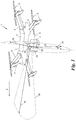
- Fig. 1 shows an aircraft 1 with a laser scanner 2 for surveying an environment, such as a landscape, a valley, a city, a street canyon, the interior of a mining pit or a mine, or the like.
- the aircraft 1 is preferred, though not mandatory, an unmanned aerial vehicle ("UAV") with a hull 3, four cantilevered arms 4 and eight rotors 5, two each on an arm 4, a so-called.
- UAV unmanned aerial vehicle
- the aircraft 1 may also be of a different type, for example a bi-tri, tri, quadro or hexacopter, a helicopter or a surface aircraft, in each case manned or unmanned.
- Such an aircraft 1 has a controller 6 which sends control values w via control lines 7 to motors 8 of the rotors 5 for their control.
- the controller 6 has an autopilot or receives control signals q via a transceiver 9 with control line 10 from a remote control 11.
- the transceiver 9 and the remote control 11 are connected via a radio link and use each antenna 12, 13.
- the aircraft used. 1 Position signals p or position data ⁇ of a global navigation satellite system (GNSS) 16 or inertial measurement unit (IMU) 17 connected via lines 14, 15 in order to control the aircraft 1.
- GNSS global navigation satellite system
- IMU inertial measurement unit
- Said laser scanner 2 emits a multiplicity of laser beams 18 in different transmission angles ⁇ around an axis S ( Fig. 1 ).
- a reference zero point for the transmission angle ⁇ can be selected any direction, such as a vertical Aussenderaum.
- the laser scanner 2 generates, for example, a single pulsed or modulated laser beam 18 which is deflected by an optical system (not shown) rotating or oscillating in the scanner head 19, whereby the laser beam 18 oscillates or rotates about the axis S.
- the laser scanner 2 can have a multiplicity of laser sources and use different laser sources for different transmission angles ⁇ .
- the laser scanner 1 is a 2D laser scanner with a 360 ° all-round window 20 for a laser beam 18 rotating about the axis S.
- a "2D laser scanner” is used in the present description a laser scanner understood, the laser beams 18 in a scanning plane normal or oblique to the axis S, to emit a scanning disk 21 to the environment. From the transit times L of the laser beams 18 reflected from the surroundings, a 2D profile of the surroundings can be created, which corresponds to the intersection of the scanning plane with the surrounding relief.
- an evaluation device 22 FIG. Fig. 2
- create a 3D model M (“sampling point cloud") of the environment.
- the scanning disk 21 of the 2D laser scanner 2 can be partially circular (sector-shaped) or preferably full-circle, in which latter case the 2D laser scanner 2 is also referred to as "360 ° -2D laser scanner".
- An example of such a 360 ° -2D laser scanner is the product with the brand name VUX® from RIEGL Laser Measurement Systems GmbH in Horn, Austria.
- the evaluation device 22 receives the measured transit times L and transmission angle ⁇ of the laser beams 18 via a line 23 and links them to the position data p of the satellite navigation system 16 and / or the position data ⁇ of the inertial measuring device 17 of FIG Aircraft 1.
- the laser scanner 2 could have its own satellite navigation system and / or its own inertial measuring device (not shown) and thus be designed as an autonomous unit.
- the evaluation unit 22 could instead of the aircraft 1 also be formed directly in the laser scanner or connected to this externally.
- the evaluation device 22 can store the created three-dimensional model M in a memory 24 of the aircraft 1 or of the laser scanner 2 or send it via the transceiver 9 to an external memory 25, which has a transceiver 26 with antenna 27 for this purpose.
- the raw data, ie running times L, position data p, position data ⁇ and associated transmission angle ⁇ are also sent via the transceivers 9, 26 to an external evaluation device 28 for online or offline evaluation.
- the laser scanner 2 could also have its own transceiver.
- the remote control 11, the external memory 25, the transceiver 26 and / or the external second evaluation device 28 may also be formed as a unit.
- the laser beams 6 emitted in the angular range ⁇ about the axis S are deflected by the mirror 30 into a plane which is not normal to the axis S and form a separate scanning fan 29, which is as it were "decoupled" from the scanning disk 21.
- the scanning fan 29 is preferably parallel to the direction of flight F of the aircraft 1, as explained in detail below.
- the laser scanner 2 determines transit times L and transmission angles ⁇ for the laser beams 18 of the transmission angle subarea ⁇ deflected by the mirror 30.
- the laser scanner 2 supplies these transit times L via the line 23 to a detection device 31, which may be located in the aircraft 1 or in the laser scanner 2 itself.
- the detection device 31 continuously compares the propagation time L of the angular range ⁇ with a threshold value A from an adjustable threshold value transmitter 32, for example also with time averaging over a sliding time window. If one or more (possibly also averaged) transit time (s) L the threshold A falls below or below, the detection device 31 on a line 34 from a warning signal Al, for example to an output device 35.
- the output device 35 for example, an optical or acoustic signaling device for the pilot of the aircraft 1 or people or animals in the area be the aircraft 1.
- the warning signal Al can also be sent via the transceiver 9 to the remote control 11 and / or the second evaluation device 28 in order to warn the operator or other persons on the ground.
- the warning signal Al may alternatively or additionally also be used to cause a change in speed and / or direction of the aircraft 1, and may be supplied to a control input 36 of the controller 6 of the aircraft 1 for this purpose.
- the controller 6 or an autopilot contained therein then automatically initiates e.g. an evasive maneuver, slowing or "stopping" of the aircraft in the air to prevent a collision with an object detected by the scanning fan 29 in this way.
- the threshold value A which determines the distance within which an environmental object is detected as potentially hazardous to collision, can be predefined or preselected by the user (also via the remote control 11) or depending on the speed and / or acceleration of the aircraft 1 to adapt the collision warning or avoidance adaptively to the flight situation.
- the detection device 31 can also detect individual objects such as birds, other unmanned aerial vehicles, trees or the like. which stand out clearly from the rest of the environment. On the basis of the size and / or the shape of the object determined by means of the transit times L, this can be classified, for example on the basis of pre-determined sizes or shapes, which are stored in a table. Depending on the classification of the object may be a different Measure be taken, for example, either issued a warning or an evasive maneuver be prompted.
- the bearing of such a detected object can be determined to detect a possible collision course of the object.
- the bearing of an object is the relative angular position of the object to the direction of flight F of the aircraft. If the bearing is swept over a predetermined observation period, e.g. For several seconds or minutes, remains constant and during this time, the observed ("apparent") size of the object only increases, there is a collision course of the object. In this case, a separate (advance) alarm can be issued and / or a precautionary direction and / or speed change can be made; or the warning signal Al or the change in direction and / or speed is suppressed for transit times L already detected as below the threshold value, if no such collision course exists.
- the speed of the object can be determined if the transit times L are measured taking into account the airspeed of the aircraft 1 over a predetermined period of time.
- the mirror 30 may be rigidly mounted on the aircraft 1 or, preferably, on the laser scanner 2, resulting in a fixed angle of inclination ⁇ of the mirror 30 with respect to the axis S.
- the inclination ⁇ of the mirror 30 is thereby e.g. adjusted by means of an adjusting screw so that the mirror 30 deflects the laser beams 18 emitted in said partial area ⁇ , for example, into a plane which is parallel to a predetermined direction of flight F.
- the mirror 30 can be movably mounted on the aircraft 1 and / or the laser scanner 2 and provided with a tilting device 37, by means of which its inclination angle ⁇ can be actively adjusted by a mirror axis SA approximately normal to the axis S.
- the tilting device 37 comprises a pivot bearing 38 for the mirror 30, an actuator 39 for pivoting the mirror axis SA and a control unit 40 for controlling the actuator 39.
- the components 38, 39 and 40 may each be installed on the laser scanner 2 and / or on the aircraft 1.
- the tilting device 37 receives via line 41, 42, 43 position data p of the satellite navigation system 16, position data ⁇ of the tilt sensor 17 and / or control data q of the controller 6, the latter e.g. are representative of a direction of flight and / or speed to be taken, as dictated by the autopilot of the controller 6 or the remote control 11.
- the position and position data p, ⁇ could alternatively originate from an internal satellite navigation system or an inertial measuring device of the laser scanner (not shown).
- the control unit 40 of the tilting device 37 via the actuator 39 can adjust the inclination ⁇ of the mirror 30 about its axis SA as follows to an instantaneous and / or to be taken flight situation of the aircraft 1.
- Fig. 3a schematically shows that the aircraft 1 during forward flight is inclined by an angle ⁇ to the horizontal. If the aircraft is in a horizontal plane, ie if the flight angle ⁇ is equal to zero, the tilt angle ⁇ of the mirror 30 will generally be + 45 ° to the axis S. If the aircraft 1 is flying at a speed not equal to zero, ie if the flight angle ⁇ is not equal to zero, then the tilt angle ⁇ of the mirror 30 is generally over 45 °. In order to compensate the flight angle ⁇ of the aircraft 1, the tilting device 37 adjusts the tilt angle ⁇ of the mirror 30 in such a way that the scan fan 29 is again parallel to the direction of flight F.
- the flight angle ⁇ can be determined from the inclination sensor data ⁇ and / or from a change in the position data p.
- Fig. 3b shows a reverse flight of the aircraft 1.
- the mirror 30 can be tilted or tilted by 90 °, ie the tilt angle ⁇ is at low speeds about -45 ° to the axis S.
- can of the Mirror 30 are tilted by an additional angle proportion corresponding to the speed of the aircraft 1, as described above for the forward flight.
- Fig. 4 shows a further application and operating mode of the tilting device 37.
- the mirror 30 is tilted periodically by a swing angle ⁇ , so that a solid angle ⁇ of the environment can be measured.
- the period of the oscillation angle ⁇ is preferably substantially longer than one period of the laser scanner 2, for example 100 times longer, for example to scan 100 lines per period of the oscillation angle ⁇ .
- the embodiment of Fig. 4 ie their tilting pattern, can also with that of the Fig. 3a and 3b be combined.
- the detection device 31 can also detect the shape of an object three-dimensionally when scanning the solid angle ⁇ and thus classify it more easily as described above.
- the oscillation angle ⁇ of the mirror 30 the height of objects can also be detected, as a result of which they can be overflown as evasive maneuvers.
- the Fig. 5a and 5b show a further embodiment for the mirror 30.
- the mirror 30 in a plane normal to the axis S cutting plane of the mirror 30 may be flat or curved.
- a plane mirror 30 ' (in the Fig. 5a and 5b dotted outlines) results in a clamping angle of the scanning fan 21 as indicated by the plane of the mirror 30 'deflected laser beams 18'.
- This clamping angle can be increased or decreased when the mirror 30 in the said plane convex ( Fig. 5a ) or concave ( Fig. 5b ).
- the mirror 30 may be curved in one direction only, ie, toric, as well as in two directions, ie, spherical.
- the 6 and 7 show an exemplary attachment of the mirror 30 and the tilting device 37 on the laser scanner 2.
- the laser scanner 2 is here in an approximately U-shaped, a recess 43 forming mounting bracket 44 at the bottom of the aircraft 1 is attached. Bracket arms 45 attaching to the mounting bracket 44 support a pivot axis 46 which supports the mirror 30. The pivot axis 46 is driven by the mounted on a support arm 45 motor (actuator) 39 of the tilting device 37.
- the U-shaped mounting bracket 44 allows thereby by the recess 43 in its center, the tilting of the mirror 30 by 90 ° or more to free view in the backward direction ( Fig. 3b ) to ensure.
- the aircraft 1 and the laser scanner 2 are preferably spaced apart at an assembly distance a and the mirror 30 is preferably located within this mounting distance a.
- the mirror 30 covers a portion or preferably just that angular range ⁇ of the laser beams 18, above which the aircraft 1 is located in any case, i. E. where by the aircraft 1 a shading area for the full scan disk 21 would arise.
- the laser scanner 2 can therefore use those laser beams 18, which would be reflected without mirror 30 from the aircraft 1, by the use of the mirror 30 for collision warning.
Landscapes
- Engineering & Computer Science (AREA)
- Physics & Mathematics (AREA)
- Computer Networks & Wireless Communication (AREA)
- General Physics & Mathematics (AREA)
- Radar, Positioning & Navigation (AREA)
- Remote Sensing (AREA)
- Electromagnetism (AREA)
- Aviation & Aerospace Engineering (AREA)
- Optical Radar Systems And Details Thereof (AREA)
Claims (14)
- Aéronef doté d'un scanner laser pour la mesure d'un environnement,
où le scanner laser (2) est conçu pour émettre des rayons laser (18) avec divers angles d'émission (α) autour d'un axe (S),
où un miroir (30) est disposé sur le trajet des rayons laser (18) d'un domaine partiel (Δα) prédéterminé d'angles d'émission (a),
où le scanner laser (1) est conçu pour déterminer les temps de transit (L) des rayons laser (18) émis à la fois à l'intérieur dudit domaine partiel (Δα) et également des rayons laser (18) émis à l'extérieur dudit domaine partiel (Δα) à l'aide de leurs réflexions sur l'environnement,
caractérisé en ce que le miroir (30) dévie les rayons laser (18) émis à l'intérieure dudit domaine partiel (Δα) dans un plan qui est parallèle à une direction de vol (F) horizontale prédéterminée,
où ledit domaine partiel (Δα) comprend les rayons laser (18) en question qui auraient été réfléchis par l'aéronef (1) sans miroir (30). - Aéronef selon la revendication 1, caractérisé en ce que le scanner laser (2) est conçu pour générer les rayons laser (18) à divers angles d'émission (Δα) au moyen d'un rayon laser unique en rotation ou vibrant autour de l'axe (S).
- Aéronef selon la revendication 1 ou 2, caractérisé par un dispositif de détection (31) qui est conçu pour émettre un signal d'avertissement ou provoquer une modification de la vitesse et/ou de la direction de l'aéronef (1) lorsque le temps de transit (L) d'au moins un rayon laser (18) émis à l'intérieur dudit domaine partiel (Δα) est en-dessous d'une valeur de seuil (λ).
- Aéronef selon la revendication 3, caractérisé en ce que le dispositif de détection est conçu pour déterminer la taille et/ou la forme d'un objet de l'environnement à partir d'une suite des temps de transit (L) de divers rayons laser (18) émis à l'intérieur dudit dans ledit domaine partiel (Δα) et classer l'objet à partir de ceux-ci.
- Aéronef selon la revendication 3 ou 4, caractérisé en ce que le dispositif de détection est conçu pour déterminer le repérage concernant cet objet dans l'environnement et sa taille à partir des temps de transit (L) à l'intérieur dudit domaine partiel (Δα) et pour émettre un signal d'avertissement et/ou provoquer une modification de la vitesse et/ou de la direction de l'aéronef (1) lorsque ledit repérage reste essentiellement constant sur un intervalle de temps prédéfini pendant que la taille augmente.
- Aéronef selon l'une des revendications 3 à 5, caractérisé en ce que la valeur de seuil (λ) est dépendante d'une vitesse et/ou d'une accélération de l'aéronef (1).
- Aéronef selon l'une des revendications 1 à 6, caractérisé par un dispositif d'exploitation (22) qui est conçu pour générer un modèle tridimensionnel (M) de l'environnement à l'aide de temps de transit (L) des rayons laser (18) émis à l'extérieur dudit domaine partiel (Δα).
- Aéronef selon l'une des revendications 1 à 7, caractérisé en ce que le miroir (30) est logé sur le scanner laser (1) .
- Aéronef selon l'une des revendications 1 à 7, caractérisé par un dispositif de basculement (37) du miroir (30) au moyen duquel l'inclinaison (y) du miroir (30) par rapport à l'axe (S) est modifiable.
- Aéronef selon la revendication 9, caractérisé en ce que le dispositif de basculement (37) est conçu pour adapter l'inclinaison (y) du miroir (30) à une direction de vol (F) et/ou une vitesse de vol momentanée ou à prendre.
- Aéronef selon la revendication 10, caractérisé en ce que le dispositif de basculement (37) est conçu pour modifier périodiquement l'inclinaison (y) du miroir (30).
- Aéronef selon l'une des revendications 9 à 11, caractérisé en ce que le dispositif de basculement (37) est conçu pour basculer le miroir (30) de plus de 90°.
- Aéronef selon l'une des revendications 1 à 12, caractérisé en ce que le miroir (30) est incurvé dans un plan en coupe du miroir (30) se situant normalement par rapport à l'axe (S) .
- Aéronef selon l'une des revendications 1 à 13, caractérisé en ce que le tronc (3) de l'aéronef (1) et le scanner laser (2) sont espacés l'un par rapport à l'autre avec une distance de montage (a) et le miroir (30) se trouve à l'intérieur de cette distance de montage (a).
Priority Applications (1)
| Application Number | Priority Date | Filing Date | Title |
|---|---|---|---|
| EP16160065.5A EP3220160B9 (fr) | 2016-03-14 | 2016-03-14 | Aeronef equipe d'un lecteur laser |
Applications Claiming Priority (1)
| Application Number | Priority Date | Filing Date | Title |
|---|---|---|---|
| EP16160065.5A EP3220160B9 (fr) | 2016-03-14 | 2016-03-14 | Aeronef equipe d'un lecteur laser |
Publications (3)
| Publication Number | Publication Date |
|---|---|
| EP3220160A1 EP3220160A1 (fr) | 2017-09-20 |
| EP3220160B1 true EP3220160B1 (fr) | 2019-12-11 |
| EP3220160B9 EP3220160B9 (fr) | 2020-03-04 |
Family
ID=55527453
Family Applications (1)
| Application Number | Title | Priority Date | Filing Date |
|---|---|---|---|
| EP16160065.5A Active EP3220160B9 (fr) | 2016-03-14 | 2016-03-14 | Aeronef equipe d'un lecteur laser |
Country Status (1)
| Country | Link |
|---|---|
| EP (1) | EP3220160B9 (fr) |
Families Citing this family (5)
| Publication number | Priority date | Publication date | Assignee | Title |
|---|---|---|---|---|
| EP3306344A1 (fr) * | 2016-10-07 | 2018-04-11 | Leica Geosystems AG | Capteur de vol |
| BE1025576B1 (nl) * | 2017-09-26 | 2019-04-24 | Think 3D | Verbeterde inrichting voor 3d-mapping van een ruimte |
| CN107990874B (zh) * | 2017-11-23 | 2018-12-25 | 南京中高知识产权股份有限公司 | 一种地面高程三维激光扫描仪和扫描方法 |
| CN108759789B (zh) * | 2018-04-23 | 2021-01-08 | 宏大爆破有限公司 | 一种基于无人机的露天矿山生产调度指挥方法 |
| CN108663669A (zh) * | 2018-08-22 | 2018-10-16 | 上海华测导航技术股份有限公司 | 用于电力巡线中应用的机载激光雷达系统 |
Citations (1)
| Publication number | Priority date | Publication date | Assignee | Title |
|---|---|---|---|---|
| EP3081957A1 (fr) * | 2015-04-13 | 2016-10-19 | Helmut-Schmidt-Universität | Dispositif de detection comprenant un capteur optoelectronique et extension de plage de mesure |
Family Cites Families (6)
| Publication number | Priority date | Publication date | Assignee | Title |
|---|---|---|---|---|
| FR2724464B1 (fr) * | 1994-09-13 | 1996-11-22 | Matra Marconi Space France | Dispositif embarquable de mesure de retrodiffusion de lumiere |
| WO1999026214A1 (fr) * | 1997-11-17 | 1999-05-27 | Thermotrex Corporation | Dispositif et procede servant a detecter un danger de collision aerienne avec des fils suspendus |
| US8120754B2 (en) * | 2009-02-19 | 2012-02-21 | Northrop Grumman Systems Corporation | Light detection and ranging apparatus |
| JP2014098603A (ja) * | 2012-11-14 | 2014-05-29 | Toshiba Corp | 3次元モデル生成装置 |
| DE102014211050B4 (de) * | 2014-06-10 | 2020-10-08 | Fraunhofer-Gesellschaft zur Förderung der angewandten Forschung e.V. | Bildgebende Vorrichtung mit flugfähiger Tragevorrichtung |
| US10088558B2 (en) * | 2014-08-15 | 2018-10-02 | Aeye, Inc. | Method and system for ladar transmission with spiral dynamic scan patterns |
-
2016
- 2016-03-14 EP EP16160065.5A patent/EP3220160B9/fr active Active
Patent Citations (1)
| Publication number | Priority date | Publication date | Assignee | Title |
|---|---|---|---|---|
| EP3081957A1 (fr) * | 2015-04-13 | 2016-10-19 | Helmut-Schmidt-Universität | Dispositif de detection comprenant un capteur optoelectronique et extension de plage de mesure |
Also Published As
| Publication number | Publication date |
|---|---|
| EP3220160B9 (fr) | 2020-03-04 |
| EP3220160A1 (fr) | 2017-09-20 |
Similar Documents
| Publication | Publication Date | Title |
|---|---|---|
| EP3220160B1 (fr) | Aeronef equipe d'un lecteur laser | |
| EP2534443B1 (fr) | Système d'arpentage d'un sol | |
| CN114503046B (zh) | 一种飞行器 | |
| DE4301637C2 (de) | Verfahren zum Andocken eines Flugzeuges an eine Fluggastbrücke eines Flughafengebäudes | |
| DE102018205134B4 (de) | Abstandssensorsystem zur effizienten und automatischen Detektion von Landeplätzen für autonome schwebeflugfähige Fluggeräte | |
| KR102408372B1 (ko) | 라이다 센서가 구비된 무인 비행체를 포함하는 산림 방재 시스템 | |
| WO2019110221A1 (fr) | Procédé pour faire fonctionner un capteur lidar, capteur lidar et moyen de locomotion | |
| FR3087915A1 (fr) | Dispositif anticollision, systeme avionique de protection, procede d'anticollision et programme d'ordinateur associes | |
| EP3559770A1 (fr) | Procédé de fonctionnement d'un appareil de nettoyage à déplacement automatique ainsi qu'un tel appareil de nettoyage | |
| WO2017177246A1 (fr) | Scanner laser | |
| WO2019233701A1 (fr) | Procédé et dispositif pour la mesure de vibrations d'un objet par l'utilisation d'un drone | |
| WO2024046688A1 (fr) | Système lidar et procédé de fonctionnement d'un système lidar | |
| DE102010051561A1 (de) | Automatisierte Landung unbemannter Flugobjekte | |
| EP4012441B1 (fr) | Dispositif de mesure laser d'un environnement | |
| EP3545338B1 (fr) | Dispositif de réception pour un dispositif de détection optique, dispositif de détection et système d'aide à la conduite | |
| WO2019096585A1 (fr) | Unité de mesure de distance | |
| EP4478083B1 (fr) | Scanner multi-plan et procédé de détection d'objets | |
| DE102018110549A1 (de) | Verfahren zum Betreiben einer Laserscanvorrichtung und Laserscanvorrichtung | |
| EP4189422A1 (fr) | Dispositif de transmission d'un dispositif de détection optique, dispositif de détection, véhicule et procédé | |
| US20230113669A1 (en) | Lidar Sensor with a Redundant Beam Scan | |
| EP4063915B1 (fr) | Dispositif de mesure d'un environnement | |
| AT510115B1 (de) | Opto-elektronisches vermessungsverfahren | |
| DE19709097A1 (de) | Flugführungssystem für tieffliegende Fluggeräte | |
| DE102017103981A1 (de) | Sendesignal-Umlenkanordnung für eine optische Sendeeinrichtung einer optischen Detektionsvorrichtung eines Fahrzeugs, Sendeeinrichtung, optische Detektionsvorrichtung und Fahrerassistenzsystem | |
| AT519765B1 (de) | Laserscanner und Vorrichtung zur Vermessung einer Umgebung |
Legal Events
| Date | Code | Title | Description |
|---|---|---|---|
| PUAI | Public reference made under article 153(3) epc to a published international application that has entered the european phase |
Free format text: ORIGINAL CODE: 0009012 |
|
| STAA | Information on the status of an ep patent application or granted ep patent |
Free format text: STATUS: THE APPLICATION HAS BEEN PUBLISHED |
|
| AK | Designated contracting states |
Kind code of ref document: A1 Designated state(s): AL AT BE BG CH CY CZ DE DK EE ES FI FR GB GR HR HU IE IS IT LI LT LU LV MC MK MT NL NO PL PT RO RS SE SI SK SM TR |
|
| AX | Request for extension of the european patent |
Extension state: BA ME |
|
| STAA | Information on the status of an ep patent application or granted ep patent |
Free format text: STATUS: REQUEST FOR EXAMINATION WAS MADE |
|
| 17P | Request for examination filed |
Effective date: 20171005 |
|
| RBV | Designated contracting states (corrected) |
Designated state(s): AL AT BE BG CH CY CZ DE DK EE ES FI FR GB GR HR HU IE IS IT LI LT LU LV MC MK MT NL NO PL PT RO RS SE SI SK SM TR |
|
| STAA | Information on the status of an ep patent application or granted ep patent |
Free format text: STATUS: EXAMINATION IS IN PROGRESS |
|
| 17Q | First examination report despatched |
Effective date: 20190326 |
|
| GRAP | Despatch of communication of intention to grant a patent |
Free format text: ORIGINAL CODE: EPIDOSNIGR1 |
|
| STAA | Information on the status of an ep patent application or granted ep patent |
Free format text: STATUS: GRANT OF PATENT IS INTENDED |
|
| INTG | Intention to grant announced |
Effective date: 20190716 |
|
| GRAJ | Information related to disapproval of communication of intention to grant by the applicant or resumption of examination proceedings by the epo deleted |
Free format text: ORIGINAL CODE: EPIDOSDIGR1 |
|
| STAA | Information on the status of an ep patent application or granted ep patent |
Free format text: STATUS: EXAMINATION IS IN PROGRESS |
|
| INTC | Intention to grant announced (deleted) | ||
| GRAR | Information related to intention to grant a patent recorded |
Free format text: ORIGINAL CODE: EPIDOSNIGR71 |
|
| GRAS | Grant fee paid |
Free format text: ORIGINAL CODE: EPIDOSNIGR3 |
|
| STAA | Information on the status of an ep patent application or granted ep patent |
Free format text: STATUS: GRANT OF PATENT IS INTENDED |
|
| GRAA | (expected) grant |
Free format text: ORIGINAL CODE: 0009210 |
|
| STAA | Information on the status of an ep patent application or granted ep patent |
Free format text: STATUS: THE PATENT HAS BEEN GRANTED |
|
| AK | Designated contracting states |
Kind code of ref document: B1 Designated state(s): AL AT BE BG CH CY CZ DE DK EE ES FI FR GB GR HR HU IE IS IT LI LT LU LV MC MK MT NL NO PL PT RO RS SE SI SK SM TR |
|
| INTG | Intention to grant announced |
Effective date: 20191104 |
|
| REG | Reference to a national code |
Ref country code: GB Ref legal event code: FG4D Free format text: NOT ENGLISH |
|
| REG | Reference to a national code |
Ref country code: CH Ref legal event code: EP |
|
| REG | Reference to a national code |
Ref country code: AT Ref legal event code: REF Ref document number: 1212743 Country of ref document: AT Kind code of ref document: T Effective date: 20191215 |
|
| REG | Reference to a national code |
Ref country code: CH Ref legal event code: NV Representative=s name: HEPP WENGER RYFFEL AG, CH |
|
| REG | Reference to a national code |
Ref country code: DE Ref legal event code: R096 Ref document number: 502016007940 Country of ref document: DE |
|
| REG | Reference to a national code |
Ref country code: IE Ref legal event code: FG4D Free format text: LANGUAGE OF EP DOCUMENT: GERMAN |
|
| REG | Reference to a national code |
Ref country code: CH Ref legal event code: PK Free format text: BERICHTIGUNG B9 |
|
| REG | Reference to a national code |
Ref country code: NL Ref legal event code: MP Effective date: 20191211 |
|
| REG | Reference to a national code |
Ref country code: LT Ref legal event code: MG4D |
|
| PG25 | Lapsed in a contracting state [announced via postgrant information from national office to epo] |
Ref country code: LT Free format text: LAPSE BECAUSE OF FAILURE TO SUBMIT A TRANSLATION OF THE DESCRIPTION OR TO PAY THE FEE WITHIN THE PRESCRIBED TIME-LIMIT Effective date: 20191211 Ref country code: NO Free format text: LAPSE BECAUSE OF FAILURE TO SUBMIT A TRANSLATION OF THE DESCRIPTION OR TO PAY THE FEE WITHIN THE PRESCRIBED TIME-LIMIT Effective date: 20200311 Ref country code: GR Free format text: LAPSE BECAUSE OF FAILURE TO SUBMIT A TRANSLATION OF THE DESCRIPTION OR TO PAY THE FEE WITHIN THE PRESCRIBED TIME-LIMIT Effective date: 20200312 Ref country code: LV Free format text: LAPSE BECAUSE OF FAILURE TO SUBMIT A TRANSLATION OF THE DESCRIPTION OR TO PAY THE FEE WITHIN THE PRESCRIBED TIME-LIMIT Effective date: 20191211 Ref country code: SE Free format text: LAPSE BECAUSE OF FAILURE TO SUBMIT A TRANSLATION OF THE DESCRIPTION OR TO PAY THE FEE WITHIN THE PRESCRIBED TIME-LIMIT Effective date: 20191211 Ref country code: BG Free format text: LAPSE BECAUSE OF FAILURE TO SUBMIT A TRANSLATION OF THE DESCRIPTION OR TO PAY THE FEE WITHIN THE PRESCRIBED TIME-LIMIT Effective date: 20200311 Ref country code: FI Free format text: LAPSE BECAUSE OF FAILURE TO SUBMIT A TRANSLATION OF THE DESCRIPTION OR TO PAY THE FEE WITHIN THE PRESCRIBED TIME-LIMIT Effective date: 20191211 |
|
| PG25 | Lapsed in a contracting state [announced via postgrant information from national office to epo] |
Ref country code: RS Free format text: LAPSE BECAUSE OF FAILURE TO SUBMIT A TRANSLATION OF THE DESCRIPTION OR TO PAY THE FEE WITHIN THE PRESCRIBED TIME-LIMIT Effective date: 20191211 Ref country code: HR Free format text: LAPSE BECAUSE OF FAILURE TO SUBMIT A TRANSLATION OF THE DESCRIPTION OR TO PAY THE FEE WITHIN THE PRESCRIBED TIME-LIMIT Effective date: 20191211 |
|
| PG25 | Lapsed in a contracting state [announced via postgrant information from national office to epo] |
Ref country code: AL Free format text: LAPSE BECAUSE OF FAILURE TO SUBMIT A TRANSLATION OF THE DESCRIPTION OR TO PAY THE FEE WITHIN THE PRESCRIBED TIME-LIMIT Effective date: 20191211 |
|
| PG25 | Lapsed in a contracting state [announced via postgrant information from national office to epo] |
Ref country code: ES Free format text: LAPSE BECAUSE OF FAILURE TO SUBMIT A TRANSLATION OF THE DESCRIPTION OR TO PAY THE FEE WITHIN THE PRESCRIBED TIME-LIMIT Effective date: 20191211 Ref country code: PT Free format text: LAPSE BECAUSE OF FAILURE TO SUBMIT A TRANSLATION OF THE DESCRIPTION OR TO PAY THE FEE WITHIN THE PRESCRIBED TIME-LIMIT Effective date: 20200506 Ref country code: EE Free format text: LAPSE BECAUSE OF FAILURE TO SUBMIT A TRANSLATION OF THE DESCRIPTION OR TO PAY THE FEE WITHIN THE PRESCRIBED TIME-LIMIT Effective date: 20191211 Ref country code: CZ Free format text: LAPSE BECAUSE OF FAILURE TO SUBMIT A TRANSLATION OF THE DESCRIPTION OR TO PAY THE FEE WITHIN THE PRESCRIBED TIME-LIMIT Effective date: 20191211 Ref country code: NL Free format text: LAPSE BECAUSE OF FAILURE TO SUBMIT A TRANSLATION OF THE DESCRIPTION OR TO PAY THE FEE WITHIN THE PRESCRIBED TIME-LIMIT Effective date: 20191211 Ref country code: RO Free format text: LAPSE BECAUSE OF FAILURE TO SUBMIT A TRANSLATION OF THE DESCRIPTION OR TO PAY THE FEE WITHIN THE PRESCRIBED TIME-LIMIT Effective date: 20191211 |
|
| PG25 | Lapsed in a contracting state [announced via postgrant information from national office to epo] |
Ref country code: SK Free format text: LAPSE BECAUSE OF FAILURE TO SUBMIT A TRANSLATION OF THE DESCRIPTION OR TO PAY THE FEE WITHIN THE PRESCRIBED TIME-LIMIT Effective date: 20191211 Ref country code: IS Free format text: LAPSE BECAUSE OF FAILURE TO SUBMIT A TRANSLATION OF THE DESCRIPTION OR TO PAY THE FEE WITHIN THE PRESCRIBED TIME-LIMIT Effective date: 20200411 Ref country code: SM Free format text: LAPSE BECAUSE OF FAILURE TO SUBMIT A TRANSLATION OF THE DESCRIPTION OR TO PAY THE FEE WITHIN THE PRESCRIBED TIME-LIMIT Effective date: 20191211 |
|
| REG | Reference to a national code |
Ref country code: DE Ref legal event code: R097 Ref document number: 502016007940 Country of ref document: DE |
|
| PLBE | No opposition filed within time limit |
Free format text: ORIGINAL CODE: 0009261 |
|
| STAA | Information on the status of an ep patent application or granted ep patent |
Free format text: STATUS: NO OPPOSITION FILED WITHIN TIME LIMIT |
|
| PG25 | Lapsed in a contracting state [announced via postgrant information from national office to epo] |
Ref country code: DK Free format text: LAPSE BECAUSE OF FAILURE TO SUBMIT A TRANSLATION OF THE DESCRIPTION OR TO PAY THE FEE WITHIN THE PRESCRIBED TIME-LIMIT Effective date: 20191211 Ref country code: MC Free format text: LAPSE BECAUSE OF FAILURE TO SUBMIT A TRANSLATION OF THE DESCRIPTION OR TO PAY THE FEE WITHIN THE PRESCRIBED TIME-LIMIT Effective date: 20191211 |
|
| 26N | No opposition filed |
Effective date: 20200914 |
|
| PG25 | Lapsed in a contracting state [announced via postgrant information from national office to epo] |
Ref country code: SI Free format text: LAPSE BECAUSE OF FAILURE TO SUBMIT A TRANSLATION OF THE DESCRIPTION OR TO PAY THE FEE WITHIN THE PRESCRIBED TIME-LIMIT Effective date: 20191211 |
|
| REG | Reference to a national code |
Ref country code: BE Ref legal event code: MM Effective date: 20200331 |
|
| PG25 | Lapsed in a contracting state [announced via postgrant information from national office to epo] |
Ref country code: LU Free format text: LAPSE BECAUSE OF NON-PAYMENT OF DUE FEES Effective date: 20200314 |
|
| PG25 | Lapsed in a contracting state [announced via postgrant information from national office to epo] |
Ref country code: IT Free format text: LAPSE BECAUSE OF FAILURE TO SUBMIT A TRANSLATION OF THE DESCRIPTION OR TO PAY THE FEE WITHIN THE PRESCRIBED TIME-LIMIT Effective date: 20191211 Ref country code: IE Free format text: LAPSE BECAUSE OF NON-PAYMENT OF DUE FEES Effective date: 20200314 |
|
| PG25 | Lapsed in a contracting state [announced via postgrant information from national office to epo] |
Ref country code: BE Free format text: LAPSE BECAUSE OF NON-PAYMENT OF DUE FEES Effective date: 20200331 Ref country code: PL Free format text: LAPSE BECAUSE OF FAILURE TO SUBMIT A TRANSLATION OF THE DESCRIPTION OR TO PAY THE FEE WITHIN THE PRESCRIBED TIME-LIMIT Effective date: 20191211 |
|
| REG | Reference to a national code |
Ref country code: AT Ref legal event code: MM01 Ref document number: 1212743 Country of ref document: AT Kind code of ref document: T Effective date: 20210314 |
|
| PG25 | Lapsed in a contracting state [announced via postgrant information from national office to epo] |
Ref country code: TR Free format text: LAPSE BECAUSE OF FAILURE TO SUBMIT A TRANSLATION OF THE DESCRIPTION OR TO PAY THE FEE WITHIN THE PRESCRIBED TIME-LIMIT Effective date: 20191211 Ref country code: MT Free format text: LAPSE BECAUSE OF FAILURE TO SUBMIT A TRANSLATION OF THE DESCRIPTION OR TO PAY THE FEE WITHIN THE PRESCRIBED TIME-LIMIT Effective date: 20191211 Ref country code: CY Free format text: LAPSE BECAUSE OF FAILURE TO SUBMIT A TRANSLATION OF THE DESCRIPTION OR TO PAY THE FEE WITHIN THE PRESCRIBED TIME-LIMIT Effective date: 20191211 |
|
| PG25 | Lapsed in a contracting state [announced via postgrant information from national office to epo] |
Ref country code: MK Free format text: LAPSE BECAUSE OF FAILURE TO SUBMIT A TRANSLATION OF THE DESCRIPTION OR TO PAY THE FEE WITHIN THE PRESCRIBED TIME-LIMIT Effective date: 20191211 |
|
| PG25 | Lapsed in a contracting state [announced via postgrant information from national office to epo] |
Ref country code: AT Free format text: LAPSE BECAUSE OF NON-PAYMENT OF DUE FEES Effective date: 20210314 |
|
| P01 | Opt-out of the competence of the unified patent court (upc) registered |
Effective date: 20230601 |
|
| PGFP | Annual fee paid to national office [announced via postgrant information from national office to epo] |
Ref country code: CH Payment date: 20250401 Year of fee payment: 10 |
|
| REG | Reference to a national code |
Ref country code: CH Ref legal event code: U11 Free format text: ST27 STATUS EVENT CODE: U-0-0-U10-U11 (AS PROVIDED BY THE NATIONAL OFFICE) Effective date: 20260401 |
|
| PGFP | Annual fee paid to national office [announced via postgrant information from national office to epo] |
Ref country code: GB Payment date: 20260324 Year of fee payment: 11 |
|
| PGFP | Annual fee paid to national office [announced via postgrant information from national office to epo] |
Ref country code: DE Payment date: 20260320 Year of fee payment: 11 |
|
| PGFP | Annual fee paid to national office [announced via postgrant information from national office to epo] |
Ref country code: FR Payment date: 20260324 Year of fee payment: 11 |