EP3220167B1 - Pilotage pour couverture dans des campagnes d'acquisition sismiques - Google Patents
Pilotage pour couverture dans des campagnes d'acquisition sismiques Download PDFInfo
- Publication number
- EP3220167B1 EP3220167B1 EP17305276.2A EP17305276A EP3220167B1 EP 3220167 B1 EP3220167 B1 EP 3220167B1 EP 17305276 A EP17305276 A EP 17305276A EP 3220167 B1 EP3220167 B1 EP 3220167B1
- Authority
- EP
- European Patent Office
- Prior art keywords
- line
- steering
- coverage
- seismic
- offset
- Prior art date
- Legal status (The legal status is an assumption and is not a legal conclusion. Google has not performed a legal analysis and makes no representation as to the accuracy of the status listed.)
- Active
Links
Images




Classifications
-
- G—PHYSICS
- G01—MEASURING; TESTING
- G01V—GEOPHYSICS; GRAVITATIONAL MEASUREMENTS; DETECTING MASSES OR OBJECTS; TAGS
- G01V1/00—Seismology; Seismic or acoustic prospecting or detecting
- G01V1/38—Seismology; Seismic or acoustic prospecting or detecting specially adapted for water-covered areas
- G01V1/3808—Seismic data acquisition, e.g. survey design
Definitions
- Embodiments of the subject matter disclosed herein generally relate to methods and systems for marine seismic data acquisition and, more particularly, to mechanisms and techniques for adjusting the steering of vessels, sources and/or receivers used to perform seismic surveys in a way that minimizes the number of acquisition lines needed to achieve full coverage of the area being surveyed, while also adhering to the quality criteria of the acquisition.
- Marine seismic data acquisition and processing techniques are used to generate a profile (image) of a geophysical structure (subsurface) under the seafloor.
- This profile does not necessarily provide an accurate location for oil and gas reservoirs, but it may suggest, to those trained in the field, the presence or absence of oil and/or gas reservoirs.
- image of the subsurface is a necessary tool today for those drilling exploration wells for minimizing the potential of finding a dry well.
- providing a better image of the subsurface is an ongoing process.
- Marine seismic surveying is designed to image the sub-surface of the earth over a specific area.
- the principle of the acquisition of the seismic data is to sample the targeted area by traversing programed adjacent and parallel sail lines over the targeted area with a vessel towing a seismic spread composed of one or more source arrays and one or more receivers.
- the data has to be acquired continuously over the area.
- the quality of the distribution of the source and receivers positions during the acquisition is monitored by the analysis of the surface-derived seismic coverage on the bin grid.
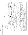
- a marine seismic data acquisition system 100 includes a survey vessel 102 towing a plurality of streamers 104 (one shown) that may extend over kilometers behind the vessel.
- One or more source arrays 106 may also be towed by the survey vessel 102 or another survey vessel (not shown) for generating seismic waves 108.
- the source arrays 106 are placed in front of the streamers 104, considering a traveling direction of the survey vessel 102.
- the seismic waves 108 generated by the source arrays 106 propagate downward and penetrate the seafloor 110, eventually being reflected by a reflecting structure 112, 114, 116, 118 at an interface between different layers of the subsurface, back to the surface 119.
- the reflected seismic waves 120 propagate upward and are detected by detectors 122 provided on the streamers 104. This process is generally referred to as "shooting" a particular seafloor 110 area.
- Each marine seismic acquisition is typically designed in advance of the survey vessel(s) actually traversing the area to be imaged.
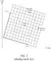
- the area to be imaged can be divided into a grid of bins that have a set size depending on the acquisition parameters, typically 12.5 ⁇ 6.25 meters (see Figure 2 ).
- the coverage is computed by calculating the number of mid positions of the triggered seismic source and of the receivers within the streamers that are located within each bin.
- CMPs common mid-points
- offsets source/receiver distances
- offset classes/categories e.g., near offset, mid offset and far offset.
- the mid-points could be also classified by azimuth of the source receiver direction.
- a typical quality criterion for seismic coverage is the number of mid-points located within a bin (fold) for a given offset class.
- Such quality criteria will typically be part of the survey specifications established, e.g., by the customer of the survey in conjunction with the survey designer.
- the survey time is mainly driven by the spread width and the size of the survey area; in this case, the seismic coverage is uniform and corresponds to nominal perfect fold.
- the movement of seismic sources and streamers is very dynamic, responding to vessel steering, and more unpredictably, the effects of ocean currents.
- the efficiency of the acquisition is related to the ability of the system to position the seismic spread such that the mid-point positions calculated during the acquisition design fill each bin with the minimal required coverage while at the same time also minimizing the number of over-folded bins. This, in turn, will minimize the number of sail lines to be traversed by the seismic vessel.
- any area where the bins are filled with less than the nominal fold is subject to an assessment as to whether an additional pass with the seismic spread is required or not.
- the size of the "holes" i.e., area where the fold is less than nominal
- the amount of mid points into the bins compared to nominal fold in percentage
- Several tools and strategies are available for assisting the vessel, the source and the spread of receivers to follow the pre-determined tracks associated with the binning grid described above with respect to Figure 2 when guiding the survey vessel(s) along their sail lines.
- These tools and strategies include, for example, source pre-plot smoothing, current prediction to match feather, line selection schedule and timing, weather and current monitoring, dynamic source steering system (e.g., winch based, deflector based systems), receiver / streamer steering system, steering controller, vessel steering optimization, active deflectors / wing steering , etc.
- the vessel steering system is a central contributor for achieving any strategy to properly position a point of interest (e.g., center of sources or source receiver mid-point) within the spread along a pre-determined track.
- a point of interest e.g., center of sources or source receiver mid-point
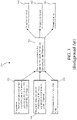
- An example of an optimized steering system 300 on-board a seismic vessel which can be used to steer the vessel along the predetermined tracks is depicted in Figure 3 .
- a first input used in the navigation system 300 is the pre-planning information described above, e.g., the definition and selection of the predetermined tracks.
- Additional inputs include information provided by an integrated navigation system, e.g., information regarding the current position of the equipment towed by the survey vessel(s) relative to a point of interest (block 304) and environmental information such as current and/or wind information collected by environmental sensors (block 306).
- controllers 308 e.g., processors, which take this data and output control information for steering the vessel(s), sources, streamers and/or deflectors, etc.
- This output control information is then sent to the actuator(s) that are responsible for manipulating the different elements to perform the steering, e.g., an autopilot 310, on-board actuators 312 and/or at-sea actuators 314.
- the term "at least one steering element” refers to one or more of the elements 308, 310, 312 and 314.
- a second drawback is that the optimization is done visually by an operator to try to achieve two different objectives, i.e., to avoid creating holes in the coverage which require infill passes and to also avoid overfilling the bins to optimize the number of passes required to cover the full survey area, which objectives are typically in conflict with one another:
- Another, more recent, technique for steering vessels during seismic surveys is to maintain a null steering offset with regards to the pre-plot line in the anticipation of repeating the same acquisition for 4D purposes and reservoir monitoring over time.
- a main drawback of this more recent technique is that while setting a null steering offset indeed facilitates the 4D survey which may be performed later, it also may result, for instance in the case of varying sea current conditions, in poor global coverage of the area being surveyed such that additional sail lines are required to achieve the targeted coverage.
- Coverage boundaries for a current line in a seismic survey and for an already-acquired adjacent line in the seismic survey are computed.
- Cross-line distances between the coverage boundary for the current line and the coverage boundary for the adjacent line are computed based on a set of specifications for the seismic survey.
- a steering point associated with towed seismic equipment is determined based on the computed cross-line distances.
- a least one steering command for a steering element in the marine seismic acquisition system is generated based on the determined steering point.
- the system includes at least one vessel that tows seismic equipment capable of generating and/or receiving seismic waves, as well as a processor, associated with a navigation system.
- the processor is configured to compute coverage boundaries for a current line in a seismic survey and for an already-acquired adjacent line in the seismic survey; compute cross-line distances between the coverage boundary for the current line and the coverage boundary for the adjacent line based on a set of specifications for the seismic survey; determine a steering point associated with towed seismic equipment based on the computed cross-line distances; and generate at least one steering command for a steering element in the system based on the determined steering point.
- the embodiments to be discussed next are not limited to this configuration, but may be applied to a streamer vessel that tows a source array and applies source steering to remove the errors due to the vessel navigation, for instance on a 4-dimensional (4D) survey, or to a source vessel without source steering to perform, for example, undershoot on a 4D survey, or to a streamer vessel with no source steering, to a vessel in a multi-vessel WAZ configuration, to a vessel performing coil shooting, to standard 3D or other configurations.
- the embodiments could also be applied to configurations where actuators (e.g., steering devices) are located on sources and on streamers and used to laterally and vertically steer the seismic spread (e.g. fanning, variable depth streamers).
- steering of a seismic vessel is performed taking into account both geographic information (i.e., x/y coordinates) and geophysical information (i.e., offset and/or azimuth) associated with a current acquisition line and the already acquired adjacent line in the survey.
- geographic information i.e., x/y coordinates
- geophysical information i.e., offset and/or azimuth
- a steering point or direction for the vessel can be selected in an automated manner which provides a good balance between the competing survey interests described above in the Background section, i.e., to avoid the creation of holes in the coverage which require infill passes and to also avoid overfilling the bins to optimize the number of passes required to cover the full survey area.
- a general method embodiment 400 is illustrated in the flowchart of Figure 4 .
- a method for configuring a marine seismic acquisition system includes the step 402 of computing coverage boundaries for a current line in a seismic survey and for an already acquired adjacent line in the seismic survey. As mentioned above, according to an embodiment (which is described in more detail below) this step 402 takes into account both geographic and geophysical information.
- step 404 cross-line distances are computed between the coverage boundary for the current line and the coverage boundary for the adjacent line based on a set of specifications for the seismic survey.
- a steering point associated with towed seismic equipment is determined based on the computed cross-line distances. This steering point (also sometimes referred to herein as a "point to steer”) is then used, at step 408 to generate a command for a steering element in the marine seismic acquisition system.
- steering element can refer to any element involved in the steering of one or more steerable devices found in marine seismic acquisition systems, i.e., elements usable to steer the vessel (e.g., rudder), elements usable to steer the sources, and/or elements usable to steer the receivers.
- a marine seismic acquisition system 500 includes a vessel 502 and two source arrays 504 and 506 and is in the process of performing a seismic survey.
- Figure 5 illustrates a past path 502a over the ground of vessel 502, and the expected or desired tracks (i.e., the pre-plot tracks which were determined before the survey was started) 504a and 506a for source arrays 504 and 506, respectively.
- the pre-plots 504a and 506a of each source array are replaced or completed by a single pre-plot 505, which represents the mid-point between source arrays 504 and 506.
- each vessel it is conventional to tow a source array that includes three sub-arrays.
- Each sub-array includes a float to which individual source elements are attached.
- all the individual source elements may be located at a same or different depth.
- each vessel tows two or more source arrays.
- source arrays 504 and 506 follow pre-plot tracks 504a and 506a within a couple of meters. Even with no wind, no current and no waves, just the inherent hydrodynamic forces and drag would make the vessel and the sources deviate from their tracks.
- initial estimates of the sources' positions are determined relative to the vessel's position by technology such as RGPS (relative GPS) giving a bearing and distance to a reference point on the vessel (usually a GPS antenna). This leads to the determination of a real time estimate of the paths over the ground of the sources.
- RGPS relative GPS
- the source arrays 504 and 506 do not follow pre-plot tracks 504a and 506a even if the vessel follows the pre-plot track 505.
- the vessel 502 (or another steerable element associated with the marine seismic acquisition system) is steered so that the source arrays 504 and 506 more closely follow the pre-plot tracks 504a and 506a, and in a manner which is designed to reduce the need for infills, by dynamically selecting a point of interest P which is associated with the towed equipment based, at least in part, on the boundary coverage of a current line being traversed by the vessel 502 as well as the boundary coverage of a line adjacent to the current line.
- the on-board navigation system can dynamically and/or periodically determine the point of interest P, and use the determination of that point, as well as other steering information (e.g., the pre-plot tracks, survey specification criteria, etc.) to generate one or more steering commands to one or more steering elements within the marine acquisition system.
- the system may determine that the steering point is P 1 and that, at a second point in time during the survey, the system may determine that the steering point is P 2 , i.e., a point different than P 1 .
- steering points P 1 and P 2 are illustrated as being points along a line between sources 504 and 506, they are not required to be so disposed and can be any points associated with the towed equipment, i.e., steering points which are chosen based on positioning of the towed equipment rather than the positioning of the vessel.
- the navigation system In addition to this type of dynamic, real time data associated with the seismic survey as it is being performed the navigation system also has certain static data to work with when determining its steering points. For example, and in addition to the data associated with the pre-plot tracks, the navigation system will also be preprogrammed with the specification data for the survey. For each marine seismic survey, there will exist certain quality control specifications which are used to evaluate the coverage being provided by the survey and to make infill decisions based on the evaluated coverage as compared to the predetermined quality control specifications. An example of a set of quality control specifications for coverage is provided in the table below. Range/Class Near Near-Mid Mid-Far Far All Required coverage 84% 77% 80% 67% 80% Infill decision 2 bins 1 bin 2 bins 3 bins
- the quality control specifications are normally made for offset ranges along the cables.
- the streamer can be divided into four segments of equal length defining 4 distinct offset ranges/classes: near, near-mid, mid-far and far.
- the specifications above also specify a required minimum coverage that has to be achieved for each offset classes to accept/validate the acquisition line, in this exemplary case:
- the admissible spatial extent of the coverage holes for each offset class is provided in the specifications, e.g., as shown in the last row of the table. For coverage below and holes larger than these specifications, additional infill lines must be acquired to supplement the coverage.
- the above-described data can be used to generate steering points, and steering commands based on those steering points, according to, for example, the above-described embodiment of Figure 4 .
- equations (1) and (2) were applied to a synthetic data set in a simulation, which synthetic data set is similar to that which might be expected to be generated in real-time by the navigation system during a seismic acquisition to calculate the coverage of the current line and the adjacent line as a function of both offset and geographical coordinates.
- the graphical results of the simulation in terms of coverage as a function of offset class are shown in Figures 7(a)-7(e) .
- the coverage C can be displayed as a shaded (or colored) map examples of which are shown in Figures 7(a)-7(e) .
- Figure 7(a) shows the coverage where h is equal to near offset
- Figure 7(b) shows the coverage where h is equal to near mid offset
- Figure 7(c) shows the coverage where h is equal to mid offset
- Figure 7(d) shows the coverage where h is equal to mid far offset
- Figure 7(e) shows the coverage where h is equal to far offset.
- the boundary can then be computed using a given minimal threshold for the fold. Typically the boundaries are obtained using the outer streamer and the sources.
- the next steps associated with the method embodiment 400 are to compute the cross line distances between the two coverage boundaries based on the survey specifications at step 404 and to determine a point of interest or steering point associated with towed seismic equipment based on the computed cross-line distances at step 406.
- These steps 404 and 406 are performed using the steps shown in the flow chart of Figure 8 and, features of which are graphically illustrated in Figures 9 and 10 .
- the coverage at each CMP of each offset class for the survey being conducted i.e., the coverage generated thus far in the survey using the real time data), can be computed.
- the cross-line distance of for each of the CMP offset classes needed to meet the coverage criteria can also be computed.
- This step 802 involves calculating cross-line distances between a CMP line 900 for the current acquisition line and the CMP line 902 from the adjacent acquisition line as shown in Figure 9 for the same inline shot points (which distances and shot points are graphically indicated by the horizontal arrows between CMP lines 900 and 902).
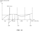
- These computed cross-line distances can then be binned by offset class to generate a distribution of the distances between the two CMP lines as a function of offset class, an example of which is shown in Figure 10 .
- a CMP at the fold limit can be selected from each offset class (i.e., where the CMP distance intersects with the fold minimal distance from the specifications in each offset class as indicated by lines 1000).
- One of these selected CMPs will then be chosen to be the steering point, as shown in Figure 11 .
- the CMP that is the most constraining at a given time is selected as the steering point, i.e., the CMP point of the offset class which corresponds to the largest crossline distance.
- one of either CMP number i1, i2, i3 and i4 are selected as the steering point or point of interest based upon this evaluation.
- a method embodiment 1200 which uses a trajectory-based function such as equation (3) to determine coverage boundaries as part of a process to determine a suitable steering point is shown in the flow chart of Figure 12 .
- the CMPs' trajectories for the outer streamer of the line adjacent to the current line in the acquisition are computed at step 1202, e.g., by using the available real time navigation data with the CMP points being the midpoint between source and receiver positions. For example, three such trajectories 1300, 1302 and 1304 associated with the adjacent line are shown in Figure 13 .
- step 1204 the cross-line distances between the CMPs' positions for the outer streamer of the current line and the corresponding CMPs positions on the trajectories of the adjacent line at the current line are computed. This is seen graphically in Figure 13 where the computed distances for step 1204 are represented by the horizontal arrows between the CMPs associated with the trajectories 1300, 1302 and 1304, and the corresponding CMPs on the outer streamer of the current line 1306, 1308 and 1310, respectively.
- the CMP that is associated with the limit of the coverage specifications is determined at step 1206, i.e., in a manner similar to that discussed above with respect to Figure 10 .
- the cross-line distances associated with the CMPs can be sorted, and the CMP for each offset class which corresponds to the specification limit can be selected.
- the CMP that has the most constraining cross-line distance is identified in step 1208 as the steering point, i.e., in a manner similar to that described above with respect to step 804 and Figure 11 .
- that steering point is used to steer at least one steering element (i.e., an actuator associated with the vessel, a bird and/or a source) to position this steering point (the selected CMP) at the distance given by the survey specifications to the outer streamer CMP of the adjacent line at step 1210.
- at least one steering element i.e., an actuator associated with the vessel, a bird and/or a source
- FIG. 14 therein a steering method 1400 is depicted which generates a steering command using a distribution of the CMPs relative to their respective computed preplot.
- the CMPs trajectories of the outer streamer of the adjacent line are computed, in a manner similar to that described above with respect to step 1402.
- the CMP trajectories are shifted based on the coverage criteria in the specifications, e.g., based on the flex bin size for each offset class.
- the cross-line distance between that CMP and its preplot is computed.
- the percentage of CMPs of the outer streamer located on each side of its preplot is calculated. For example, as shown in Figure 15 , for each of the trajectories 1502, 1504 and 1506 a percentage of CMPs on each side of that trajectory would be determined, e.g., X% on one side of trajectory 1502 and Y% on the other side of trajectory 1502.
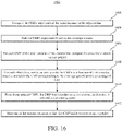
- FIG 16 is a flowchart which illustrates another steering method which is similar to the embodiment of Figure14 , except that it provides for a quantitative command using a point to steer which is selected by analyzing the distribution of the CMPs relative to their respective computed preplots, rather than a qualitative direction to steer as in the embodiment of Figure 14 .
- Steps 1602-1606 are the same as steps 1402-1406.
- step 1608 for each offset class, sort in ascending order the CMPs as a function of their crossline distance and. select the one corresponding to the coverage specification percentage of fold. From those selected CMPs, at step 1610, the CMP that is further away in the crossline direction is selected as the steering point. Then steering is performed using this steering point at step 1612.
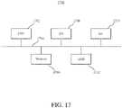
- the computing device 1700 may be a processor, a computer, a server, etc.
- the computing device 1700 may include a processor 1702 connected through a bus 1704 to a storage device 1706.
- the storage device 1706 may be any type of memory and may store necessary commands and instructions associated with positioning the sources and the streamer spreads as discussed above.
- Also connected to the bus 1704 is an input/output interface 1708 through which the operator may interact with the sources, for example, for adjusting a position of the sources based on the identified steering point.
- a communication interface 1710 is also connected to the bus 1704 and is configured to transfer information between the processor 1702 and an outside network, Internet, operator's internal network, etc.
- the communication interface 1710 may be wired or wireless.
- computing device 1700 may include a screen 1712 for displaying various results generated by the algorithms discussed above. For example, the steering point and/or adjusted tracks may be displayed, after being calculated with the novel algorithms described above, on the screen 1712.
- a navigation system such as that described above with respect to Figure 3 , can be used to generate one or more steering commands to one or more steering elements. This can be done, for example, as described in the above-described U.S. Patent Publication WO2015071491 to Tonchia, H. and Moulinier, T. , entitled “Device and Method for Steering Seismic Vessel", or using any other suitable technique and system.
Landscapes
- Life Sciences & Earth Sciences (AREA)
- Physics & Mathematics (AREA)
- Oceanography (AREA)
- Engineering & Computer Science (AREA)
- Acoustics & Sound (AREA)
- Environmental & Geological Engineering (AREA)
- Geology (AREA)
- Remote Sensing (AREA)
- General Life Sciences & Earth Sciences (AREA)
- General Physics & Mathematics (AREA)
- Geophysics (AREA)
- Geophysics And Detection Of Objects (AREA)
Claims (9)
- Procédé de configuration d'un système d'acquisition sismique marin, le procédé comprenant les étapes ci-dessous consistant à :calculer (402) des limites de couverture pour une ligne d'acquisition en cours dans une campagne d'acquisition sismique et pour une ligne d'acquisition adjacente déjà acquise dans la campagne d'acquisition sismique ;calculer (404) des distances de lignes transversales entre la limite de couverture pour la ligne d'acquisition en cours et la limite de couverture pour la ligne d'acquisition adjacente, sur la base d'un ensemble de spécifications pour la campagne d'acquisition sismique ;déterminer (406) un point de pilotage associé à un équipement sismique remorqué sur la base des distances de lignes transversales calculées ; etgénérer (408) au moins une instruction de pilotage pour un élément de pilotage dans le système d'acquisition sismique marin, sur la base du point de pilotage déterminé ;le procédé étant caractérisé en ce que les limites de couverture sont calculées en utilisant à la fois des informations géographiques et des informations géophysiques, les informations géophysiques incluant au moins l'un parmi un décalage et un azimut, et caractérisé en ce quele procédé comprend en outre les étapes ci-dessous consistant à :calculer une couverture à chaque point milieu commun, CMP, de chaque classe de décalage pour la campagne d'acquisition sismique ;déterminer une distance de ligne transversale, pour chaque classe de décalage de point CMP, nécessaire pour répondre à des critères de couverture pour la campagne d'acquisition sismique ;en utilisant les distances de lignes transversales déterminées, sélectionner un point CMP à une limite de pliage associée à la campagne d'acquisition sismique, à partir de chaque classe de décalage, la limite de pliage correspondant à la distance minimale pour chaque classe de décalage dans les spécifications de campagne d'acquisition ; etsélectionner, en tant que le point de pilotage, le point CMP associé à l'une des classes de décalage qui présente la plus grande distance de ligne transversale.
- Procédé selon la revendication 1, dans lequel le point CMP associé à l'une des classes de décalage qui présente la plus grande distance de ligne transversale est déterminé en mettant en œuvre l'étape ci-dessous consistant à :
déterminer quel point, parmi les points CMP sélectionnés pour chaque classe de décalage, présente une différence maximale entre sa distance de ligne transversale et une distance autorisée par l'ensemble de spécifications pour la campagne d'acquisition sismique. - Procédé selon la revendication 1, dans lequel les informations géophysiques incluent des trajectoires de points milieux communs, CMP.
- Procédé selon la revendication 3, comprenant en outre les étapes ci-dessous consistant à :calculer les trajectoires de points milieux communs pour une flûte marine extérieure d'une ligne adjacente à une ligne d'acquisition en cours ;calculer des distances de lignes transversales entre des positions de points CMP pour la flûte marine extérieure de la ligne d'acquisition en cours et les trajectoires calculées ;déterminer, pour chaque classe de décalage, un point CMP qui est associé à une limite de couverture fournie par l'ensemble de spécifications ;identifier, en tant que le point de pilotage, l'un des points CMP déterminés qui présente une distance de ligne transversale la plus contraignante.
- Procédé selon la revendication 3, comprenant en outre les étapes ci-dessous consistant à :calculer les trajectoires de points milieux communs pour une flûte marine extérieure d'une ligne adjacente à une ligne d'acquisition en cours ;décaler les trajectoires de points milieux communs sur la base de critères de couverture provenant de l'ensemble de spécifications, la trajectoire de point milieu commun décalée étant un tracé préalable d'un point milieu commun donné de la flûte marine extérieure de la ligne d'acquisition en cours correspondant à un décalage ;calculer, pour chaque point milieu commun de la flûte marine extérieure de la ligne d'acquisition en cours, une distance de ligne transversale avec son tracé préalable ;calculer, pour chaque classe de décalage, un pourcentage des points milieux communs de la flûte marine extérieure, situés de chaque côté du tracé préalable de cette classe de décalage ; etdéterminer une direction de pilotage sur la base d'une comparaison du pourcentage de points milieux communs de chaque côté d'une piste de tracé préalable.
- Procédé selon la revendication 3, comprenant en outre les étapes ci-dessous consistant à :calculer les trajectoires de points milieux communs pour une flûte marine extérieure d'une ligne adjacente à une ligne d'acquisition en cours ;décaler les trajectoires sur la base de critères de couverture en provenance de l'ensemble de spécifications, la trajectoire de point milieu commun décalée étant un tracé préalable d'un point milieu commun donné de la flûte marine extérieure de la ligne d'acquisition en cours correspondant à un décalage ;calculer, pour chaque point milieu commun de la flûte marine extérieure de la ligne d'acquisition en cours, une distance de ligne transversale avec son tracé préalable ;trier, pour chaque classe de décalage, par ordre croissant, les points CMP, en fonction de leur distance de ligne transversale, et sélectionner, pour chaque classe de décalage, le point CMP correspondant au pourcentage de pliage de l'ensemble de spécifications ; etsélectionner, en tant que le point de pilotage, l'un des points milieux communs sélectionnés de la classe de décalage qui est plus éloigné dans la direction de ligne transversale.
- Procédé selon la revendication 1, comprenant en outre l'étape ci-dessous consistant à :
actionner l'élément de pilotage pour piloter au moins l'un des éléments parmi un navire, une source ou un récepteur dans le système d'acquisition sismique marin, sur la base de l'instruction de pilotage. - Système de collecte de données sismiques comprenant :au moins un navire (502) qui remorque un équipement sismique (504, 506) en mesure de générer et/ou de recevoir des ondes sismiques ; etun processeur (1702), associé à un système de navigation, qui est configuré de manière à :calculer (402) des limites de couverture pour une ligne d'acquisition en cours dans une campagne d'acquisition sismique et pour une ligne d'acquisition adjacente déjà acquise dans la campagne d'acquisition sismique ;calculer (404) des distances de lignes transversales entre la limite de couverture pour la ligne d'acquisition en cours et la limite de couverture pour la ligne d'acquisition adjacente, sur la base d'un ensemble de spécifications pour la campagne d'acquisition sismique ;déterminer (406) un point de pilotage associé à un équipement sismique remorqué, sur la base des distances de lignes transversales calculées ; etgénérer (408) au moins une instruction de pilotage pour un élément de pilotage dans le système d'acquisition sismique marin, sur la base du point de pilotage déterminé ;le système étant caractérisé en ce que les limites de couverture sont calculées en utilisant à la fois des informations géographiques et des informations géophysiques, les informations géophysiques incluant au moins l'un parmi un décalage et un azimut, et caractérisé en ce quele processeur est en outre configuré de manière à :calculer une couverture à chaque point milieu commun, CMP, de chaque classe de décalage pour la campagne d'acquisition sismique ;déterminer une distance de ligne transversale, pour chaque classe de décalage de point CMP, nécessaire pour répondre à des critères de couverture pour la campagne d'acquisition sismique ;en utilisant les distances de lignes transversales déterminées, sélectionner un point CMP à une limite de pliage associée à la campagne d'acquisition sismique, à partir de chaque classe de décalage, la limite de pliage correspondant à la distance minimale pour chaque classe de décalage dans les spécifications de campagne d'acquisition ; etsélectionner, en tant que le point de pilotage, le point CMP associé à l'une des classes de décalage qui présente la plus grande distance de ligne transversale.
- Système selon la revendication 8, dans lequel le point CMP associé à l'une des classes de décalage qui présente la plus grande distance de ligne transversale est déterminé en mettant en œuvre l'étape ci-dessous consistant à :
déterminer quel point, parmi les points CMP sélectionnés pour chaque classe de décalage, présente une différence maximale entre sa distance de ligne transversale et une distance autorisée par l'ensemble de spécifications pour la campagne d'acquisition sismique.
Applications Claiming Priority (1)
| Application Number | Priority Date | Filing Date | Title |
|---|---|---|---|
| US201662308345P | 2016-03-15 | 2016-03-15 |
Publications (2)
| Publication Number | Publication Date |
|---|---|
| EP3220167A1 EP3220167A1 (fr) | 2017-09-20 |
| EP3220167B1 true EP3220167B1 (fr) | 2022-10-05 |
Family
ID=58413029
Family Applications (1)
| Application Number | Title | Priority Date | Filing Date |
|---|---|---|---|
| EP17305276.2A Active EP3220167B1 (fr) | 2016-03-15 | 2017-03-14 | Pilotage pour couverture dans des campagnes d'acquisition sismiques |
Country Status (2)
| Country | Link |
|---|---|
| US (1) | US10520624B2 (fr) |
| EP (1) | EP3220167B1 (fr) |
Families Citing this family (5)
| Publication number | Priority date | Publication date | Assignee | Title |
|---|---|---|---|---|
| EP3657127B1 (fr) * | 2018-11-21 | 2022-08-03 | Sercel | Procédé de planification d'une trajectoire en présence de courant d'eau |
| CN111665541B (zh) * | 2019-03-05 | 2023-04-25 | 中国石油天然气股份有限公司 | 三维地震物理模拟数据采集方法及装置 |
| CN112394390B (zh) * | 2019-08-15 | 2023-06-30 | 中国石油天然气集团有限公司 | 复杂地表区观测系统联合布设方法及装置 |
| CN112444847B (zh) * | 2019-08-28 | 2024-07-26 | 中国石油天然气集团有限公司 | 一种确定三维工区地震数据外边界的方法及装置 |
| US12043356B2 (en) | 2020-08-07 | 2024-07-23 | Digicourse, Llc | Control system for steerable towed marine equipment |
Family Cites Families (8)
| Publication number | Priority date | Publication date | Assignee | Title |
|---|---|---|---|---|
| US183502A (en) | 1876-10-24 | Improvement in fire-escapes | ||
| US185350A (en) | 1876-12-12 | Jothrem m | ||
| US7400552B2 (en) * | 2006-01-19 | 2008-07-15 | Westerngeco L.L.C. | Methods and systems for efficiently acquiring towed streamer seismic surveys |
| WO2012162433A2 (fr) | 2011-05-23 | 2012-11-29 | Ion Geophysical Corporation | Procédé et appareil de détermination d'un lieu pour acquérir des données géophysiques |
| MX2016006408A (es) | 2013-11-18 | 2016-08-01 | Cgg Services Sa | Dispositivo y metodo para dirigir una embarcacion sismica. |
| EP2889646A1 (fr) | 2013-12-31 | 2015-07-01 | Sercel | Procédé et dispositif pour diriger un navire sismique, sur la base des limites des zones de couverture de regroupement |
| EP2889645B1 (fr) | 2013-12-31 | 2019-02-06 | Sercel | Procédé et dispositif pour diriger un navire sismique |
| CA2954260C (fr) * | 2014-07-04 | 2020-07-14 | Ion Geophysical Corporation | Analyse d'empreinte de decalage pour selectionner des lignes candidates pour etude sismique |
-
2017
- 2017-03-14 US US15/458,329 patent/US10520624B2/en active Active
- 2017-03-14 EP EP17305276.2A patent/EP3220167B1/fr active Active
Also Published As
| Publication number | Publication date |
|---|---|
| US20170269248A1 (en) | 2017-09-21 |
| EP3220167A1 (fr) | 2017-09-20 |
| US10520624B2 (en) | 2019-12-31 |
Similar Documents
| Publication | Publication Date | Title |
|---|---|---|
| US10520624B2 (en) | Steering for coverage in seismic surveys | |
| CN101598807B (zh) | 地震观测系统设计中确定不同面元属性差异的方法 | |
| US20170090053A1 (en) | 3d seismic acquisition | |
| US20090279386A1 (en) | Method for determining adequacy of seismic data coverage of a subsurface area being surveyed | |
| US9116257B2 (en) | Method and apparatus for sea current aided, enhanced azimuth seismic data acquisition | |
| US9720120B2 (en) | Seismic data acquisition with varying relative distance between multiple seismic vessels | |
| RU2712793C2 (ru) | Заполнение в реальном времени данных при морских сейсмических съемках с использованием независимого сейсмического источника | |
| AU2016204606B2 (en) | Methods and devices for enhanced survey data collection | |
| EP3164737B1 (fr) | Analyse d'empreinte de décalage pour sélectionner des lignes candidates pour étude sismique | |
| EP2715402A2 (fr) | Procédé et appareil de détermination d'un lieu pour acquérir des données géophysiques | |
| US20240159932A1 (en) | Method for steering a vessel, related navigation system and method for seismic data acquisition | |
| Moldoveanu | Circular geometry for wide-azimuth towed-streamer acquisition | |
| EP2788793A1 (fr) | Procédé et appareil pour acquisition de données sismiques d'azimut amélioré, assistée par courant marin | |
| US9903969B2 (en) | Survey coverage parameters | |
| Abdulah et al. | Temporal and spatial sampling constraints in high-resolution 3-D seismic surveys | |
| Grillot et al. | Three-dimensional seismic interpretation: Espoir field area, offshore ivory coast |
Legal Events
| Date | Code | Title | Description |
|---|---|---|---|
| PUAI | Public reference made under article 153(3) epc to a published international application that has entered the european phase |
Free format text: ORIGINAL CODE: 0009012 |
|
| STAA | Information on the status of an ep patent application or granted ep patent |
Free format text: STATUS: THE APPLICATION HAS BEEN PUBLISHED |
|
| AK | Designated contracting states |
Kind code of ref document: A1 Designated state(s): AL AT BE BG CH CY CZ DE DK EE ES FI FR GB GR HR HU IE IS IT LI LT LU LV MC MK MT NL NO PL PT RO RS SE SI SK SM TR |
|
| AX | Request for extension of the european patent |
Extension state: BA ME |
|
| STAA | Information on the status of an ep patent application or granted ep patent |
Free format text: STATUS: REQUEST FOR EXAMINATION WAS MADE |
|
| 17P | Request for examination filed |
Effective date: 20180320 |
|
| RBV | Designated contracting states (corrected) |
Designated state(s): AL AT BE BG CH CY CZ DE DK EE ES FI FR GB GR HR HU IE IS IT LI LT LU LV MC MK MT NL NO PL PT RO RS SE SI SK SM TR |
|
| STAA | Information on the status of an ep patent application or granted ep patent |
Free format text: STATUS: EXAMINATION IS IN PROGRESS |
|
| 17Q | First examination report despatched |
Effective date: 20200706 |
|
| RAP1 | Party data changed (applicant data changed or rights of an application transferred) |
Owner name: SERCEL |
|
| GRAP | Despatch of communication of intention to grant a patent |
Free format text: ORIGINAL CODE: EPIDOSNIGR1 |
|
| STAA | Information on the status of an ep patent application or granted ep patent |
Free format text: STATUS: GRANT OF PATENT IS INTENDED |
|
| INTG | Intention to grant announced |
Effective date: 20220523 |
|
| GRAS | Grant fee paid |
Free format text: ORIGINAL CODE: EPIDOSNIGR3 |
|
| GRAA | (expected) grant |
Free format text: ORIGINAL CODE: 0009210 |
|
| STAA | Information on the status of an ep patent application or granted ep patent |
Free format text: STATUS: THE PATENT HAS BEEN GRANTED |
|
| AK | Designated contracting states |
Kind code of ref document: B1 Designated state(s): AL AT BE BG CH CY CZ DE DK EE ES FI FR GB GR HR HU IE IS IT LI LT LU LV MC MK MT NL NO PL PT RO RS SE SI SK SM TR |
|
| REG | Reference to a national code |
Ref country code: GB Ref legal event code: FG4D |
|
| REG | Reference to a national code |
Ref country code: CH Ref legal event code: EP |
|
| REG | Reference to a national code |
Ref country code: AT Ref legal event code: REF Ref document number: 1523083 Country of ref document: AT Kind code of ref document: T Effective date: 20221015 |
|
| REG | Reference to a national code |
Ref country code: DE Ref legal event code: R096 Ref document number: 602017062339 Country of ref document: DE |
|
| REG | Reference to a national code |
Ref country code: IE Ref legal event code: FG4D |
|
| REG | Reference to a national code |
Ref country code: NO Ref legal event code: T2 Effective date: 20221005 |
|
| REG | Reference to a national code |
Ref country code: LT Ref legal event code: MG9D |
|
| REG | Reference to a national code |
Ref country code: NL Ref legal event code: MP Effective date: 20221005 |
|
| REG | Reference to a national code |
Ref country code: AT Ref legal event code: MK05 Ref document number: 1523083 Country of ref document: AT Kind code of ref document: T Effective date: 20221005 |
|
| PG25 | Lapsed in a contracting state [announced via postgrant information from national office to epo] |
Ref country code: NL Free format text: LAPSE BECAUSE OF FAILURE TO SUBMIT A TRANSLATION OF THE DESCRIPTION OR TO PAY THE FEE WITHIN THE PRESCRIBED TIME-LIMIT Effective date: 20221005 |
|
| PG25 | Lapsed in a contracting state [announced via postgrant information from national office to epo] |
Ref country code: SE Free format text: LAPSE BECAUSE OF FAILURE TO SUBMIT A TRANSLATION OF THE DESCRIPTION OR TO PAY THE FEE WITHIN THE PRESCRIBED TIME-LIMIT Effective date: 20221005 Ref country code: PT Free format text: LAPSE BECAUSE OF FAILURE TO SUBMIT A TRANSLATION OF THE DESCRIPTION OR TO PAY THE FEE WITHIN THE PRESCRIBED TIME-LIMIT Effective date: 20230206 Ref country code: LT Free format text: LAPSE BECAUSE OF FAILURE TO SUBMIT A TRANSLATION OF THE DESCRIPTION OR TO PAY THE FEE WITHIN THE PRESCRIBED TIME-LIMIT Effective date: 20221005 Ref country code: FI Free format text: LAPSE BECAUSE OF FAILURE TO SUBMIT A TRANSLATION OF THE DESCRIPTION OR TO PAY THE FEE WITHIN THE PRESCRIBED TIME-LIMIT Effective date: 20221005 Ref country code: ES Free format text: LAPSE BECAUSE OF FAILURE TO SUBMIT A TRANSLATION OF THE DESCRIPTION OR TO PAY THE FEE WITHIN THE PRESCRIBED TIME-LIMIT Effective date: 20221005 Ref country code: AT Free format text: LAPSE BECAUSE OF FAILURE TO SUBMIT A TRANSLATION OF THE DESCRIPTION OR TO PAY THE FEE WITHIN THE PRESCRIBED TIME-LIMIT Effective date: 20221005 |
|
| PG25 | Lapsed in a contracting state [announced via postgrant information from national office to epo] |
Ref country code: RS Free format text: LAPSE BECAUSE OF FAILURE TO SUBMIT A TRANSLATION OF THE DESCRIPTION OR TO PAY THE FEE WITHIN THE PRESCRIBED TIME-LIMIT Effective date: 20221005 Ref country code: PL Free format text: LAPSE BECAUSE OF FAILURE TO SUBMIT A TRANSLATION OF THE DESCRIPTION OR TO PAY THE FEE WITHIN THE PRESCRIBED TIME-LIMIT Effective date: 20221005 Ref country code: LV Free format text: LAPSE BECAUSE OF FAILURE TO SUBMIT A TRANSLATION OF THE DESCRIPTION OR TO PAY THE FEE WITHIN THE PRESCRIBED TIME-LIMIT Effective date: 20221005 Ref country code: IS Free format text: LAPSE BECAUSE OF FAILURE TO SUBMIT A TRANSLATION OF THE DESCRIPTION OR TO PAY THE FEE WITHIN THE PRESCRIBED TIME-LIMIT Effective date: 20230205 Ref country code: HR Free format text: LAPSE BECAUSE OF FAILURE TO SUBMIT A TRANSLATION OF THE DESCRIPTION OR TO PAY THE FEE WITHIN THE PRESCRIBED TIME-LIMIT Effective date: 20221005 Ref country code: GR Free format text: LAPSE BECAUSE OF FAILURE TO SUBMIT A TRANSLATION OF THE DESCRIPTION OR TO PAY THE FEE WITHIN THE PRESCRIBED TIME-LIMIT Effective date: 20230106 |
|
| REG | Reference to a national code |
Ref country code: DE Ref legal event code: R097 Ref document number: 602017062339 Country of ref document: DE |
|
| PG25 | Lapsed in a contracting state [announced via postgrant information from national office to epo] |
Ref country code: SM Free format text: LAPSE BECAUSE OF FAILURE TO SUBMIT A TRANSLATION OF THE DESCRIPTION OR TO PAY THE FEE WITHIN THE PRESCRIBED TIME-LIMIT Effective date: 20221005 Ref country code: RO Free format text: LAPSE BECAUSE OF FAILURE TO SUBMIT A TRANSLATION OF THE DESCRIPTION OR TO PAY THE FEE WITHIN THE PRESCRIBED TIME-LIMIT Effective date: 20221005 Ref country code: EE Free format text: LAPSE BECAUSE OF FAILURE TO SUBMIT A TRANSLATION OF THE DESCRIPTION OR TO PAY THE FEE WITHIN THE PRESCRIBED TIME-LIMIT Effective date: 20221005 Ref country code: DK Free format text: LAPSE BECAUSE OF FAILURE TO SUBMIT A TRANSLATION OF THE DESCRIPTION OR TO PAY THE FEE WITHIN THE PRESCRIBED TIME-LIMIT Effective date: 20221005 Ref country code: CZ Free format text: LAPSE BECAUSE OF FAILURE TO SUBMIT A TRANSLATION OF THE DESCRIPTION OR TO PAY THE FEE WITHIN THE PRESCRIBED TIME-LIMIT Effective date: 20221005 |
|
| PLBE | No opposition filed within time limit |
Free format text: ORIGINAL CODE: 0009261 |
|
| STAA | Information on the status of an ep patent application or granted ep patent |
Free format text: STATUS: NO OPPOSITION FILED WITHIN TIME LIMIT |
|
| PG25 | Lapsed in a contracting state [announced via postgrant information from national office to epo] |
Ref country code: SK Free format text: LAPSE BECAUSE OF FAILURE TO SUBMIT A TRANSLATION OF THE DESCRIPTION OR TO PAY THE FEE WITHIN THE PRESCRIBED TIME-LIMIT Effective date: 20221005 Ref country code: AL Free format text: LAPSE BECAUSE OF FAILURE TO SUBMIT A TRANSLATION OF THE DESCRIPTION OR TO PAY THE FEE WITHIN THE PRESCRIBED TIME-LIMIT Effective date: 20221005 |
|
| 26N | No opposition filed |
Effective date: 20230706 |
|
| REG | Reference to a national code |
Ref country code: DE Ref legal event code: R119 Ref document number: 602017062339 Country of ref document: DE |
|
| PG25 | Lapsed in a contracting state [announced via postgrant information from national office to epo] |
Ref country code: MC Free format text: LAPSE BECAUSE OF FAILURE TO SUBMIT A TRANSLATION OF THE DESCRIPTION OR TO PAY THE FEE WITHIN THE PRESCRIBED TIME-LIMIT Effective date: 20221005 |
|
| REG | Reference to a national code |
Ref country code: CH Ref legal event code: PL |
|
| PG25 | Lapsed in a contracting state [announced via postgrant information from national office to epo] |
Ref country code: SI Free format text: LAPSE BECAUSE OF FAILURE TO SUBMIT A TRANSLATION OF THE DESCRIPTION OR TO PAY THE FEE WITHIN THE PRESCRIBED TIME-LIMIT Effective date: 20221005 |
|
| REG | Reference to a national code |
Ref country code: BE Ref legal event code: MM Effective date: 20230331 |
|
| PG25 | Lapsed in a contracting state [announced via postgrant information from national office to epo] |
Ref country code: LU Free format text: LAPSE BECAUSE OF NON-PAYMENT OF DUE FEES Effective date: 20230314 |
|
| REG | Reference to a national code |
Ref country code: IE Ref legal event code: MM4A |
|
| PG25 | Lapsed in a contracting state [announced via postgrant information from national office to epo] |
Ref country code: LI Free format text: LAPSE BECAUSE OF NON-PAYMENT OF DUE FEES Effective date: 20230331 Ref country code: IE Free format text: LAPSE BECAUSE OF NON-PAYMENT OF DUE FEES Effective date: 20230314 Ref country code: FR Free format text: LAPSE BECAUSE OF NON-PAYMENT OF DUE FEES Effective date: 20230331 Ref country code: DE Free format text: LAPSE BECAUSE OF NON-PAYMENT OF DUE FEES Effective date: 20231003 Ref country code: CH Free format text: LAPSE BECAUSE OF NON-PAYMENT OF DUE FEES Effective date: 20230331 |
|
| PG25 | Lapsed in a contracting state [announced via postgrant information from national office to epo] |
Ref country code: BE Free format text: LAPSE BECAUSE OF NON-PAYMENT OF DUE FEES Effective date: 20230331 |
|
| PG25 | Lapsed in a contracting state [announced via postgrant information from national office to epo] |
Ref country code: IT Free format text: LAPSE BECAUSE OF FAILURE TO SUBMIT A TRANSLATION OF THE DESCRIPTION OR TO PAY THE FEE WITHIN THE PRESCRIBED TIME-LIMIT Effective date: 20221005 |
|
| PG25 | Lapsed in a contracting state [announced via postgrant information from national office to epo] |
Ref country code: BG Free format text: LAPSE BECAUSE OF FAILURE TO SUBMIT A TRANSLATION OF THE DESCRIPTION OR TO PAY THE FEE WITHIN THE PRESCRIBED TIME-LIMIT Effective date: 20221005 |
|
| PG25 | Lapsed in a contracting state [announced via postgrant information from national office to epo] |
Ref country code: BG Free format text: LAPSE BECAUSE OF FAILURE TO SUBMIT A TRANSLATION OF THE DESCRIPTION OR TO PAY THE FEE WITHIN THE PRESCRIBED TIME-LIMIT Effective date: 20221005 |
|
| PGFP | Annual fee paid to national office [announced via postgrant information from national office to epo] |
Ref country code: NO Payment date: 20250321 Year of fee payment: 9 |
|
| PGFP | Annual fee paid to national office [announced via postgrant information from national office to epo] |
Ref country code: GB Payment date: 20250321 Year of fee payment: 9 |
|
| PG25 | Lapsed in a contracting state [announced via postgrant information from national office to epo] |
Ref country code: CY Free format text: LAPSE BECAUSE OF FAILURE TO SUBMIT A TRANSLATION OF THE DESCRIPTION OR TO PAY THE FEE WITHIN THE PRESCRIBED TIME-LIMIT; INVALID AB INITIO Effective date: 20170314 |
|
| PG25 | Lapsed in a contracting state [announced via postgrant information from national office to epo] |
Ref country code: HU Free format text: LAPSE BECAUSE OF FAILURE TO SUBMIT A TRANSLATION OF THE DESCRIPTION OR TO PAY THE FEE WITHIN THE PRESCRIBED TIME-LIMIT; INVALID AB INITIO Effective date: 20170314 |
|
| PG25 | Lapsed in a contracting state [announced via postgrant information from national office to epo] |
Ref country code: TR Free format text: LAPSE BECAUSE OF FAILURE TO SUBMIT A TRANSLATION OF THE DESCRIPTION OR TO PAY THE FEE WITHIN THE PRESCRIBED TIME-LIMIT Effective date: 20221005 |