EP3220186B1 - Head-up-display-vorrichtung - Google Patents
Head-up-display-vorrichtung Download PDFInfo
- Publication number
- EP3220186B1 EP3220186B1 EP15858147.0A EP15858147A EP3220186B1 EP 3220186 B1 EP3220186 B1 EP 3220186B1 EP 15858147 A EP15858147 A EP 15858147A EP 3220186 B1 EP3220186 B1 EP 3220186B1
- Authority
- EP
- European Patent Office
- Prior art keywords
- head
- display device
- mirror
- case
- shielding portion
- Prior art date
- Legal status (The legal status is an assumption and is not a legal conclusion. Google has not performed a legal analysis and makes no representation as to the accuracy of the status listed.)
- Active
Links
Images




Classifications
-
- G—PHYSICS
- G02—OPTICS
- G02B—OPTICAL ELEMENTS, SYSTEMS OR APPARATUS
- G02B27/00—Optical systems or apparatus not provided for by any of the groups G02B1/00 - G02B26/00, G02B30/00
- G02B27/01—Head-up displays
- G02B27/0101—Head-up displays characterised by optical features
-
- B—PERFORMING OPERATIONS; TRANSPORTING
- B60—VEHICLES IN GENERAL
- B60K—ARRANGEMENT OR MOUNTING OF PROPULSION UNITS OR OF TRANSMISSIONS IN VEHICLES; ARRANGEMENT OR MOUNTING OF PLURAL DIVERSE PRIME-MOVERS IN VEHICLES; AUXILIARY DRIVES FOR VEHICLES; INSTRUMENTATION OR DASHBOARDS FOR VEHICLES; ARRANGEMENTS IN CONNECTION WITH COOLING, AIR INTAKE, GAS EXHAUST OR FUEL SUPPLY OF PROPULSION UNITS IN VEHICLES
- B60K35/00—Instruments specially adapted for vehicles; Arrangement of instruments in or on vehicles
- B60K35/20—Output arrangements, i.e. from vehicle to user, associated with vehicle functions or specially adapted therefor
- B60K35/21—Output arrangements, i.e. from vehicle to user, associated with vehicle functions or specially adapted therefor using visual output, e.g. blinking lights or matrix displays
- B60K35/213—Virtual instruments
-
- B—PERFORMING OPERATIONS; TRANSPORTING
- B60—VEHICLES IN GENERAL
- B60K—ARRANGEMENT OR MOUNTING OF PROPULSION UNITS OR OF TRANSMISSIONS IN VEHICLES; ARRANGEMENT OR MOUNTING OF PLURAL DIVERSE PRIME-MOVERS IN VEHICLES; AUXILIARY DRIVES FOR VEHICLES; INSTRUMENTATION OR DASHBOARDS FOR VEHICLES; ARRANGEMENTS IN CONNECTION WITH COOLING, AIR INTAKE, GAS EXHAUST OR FUEL SUPPLY OF PROPULSION UNITS IN VEHICLES
- B60K35/00—Instruments specially adapted for vehicles; Arrangement of instruments in or on vehicles
- B60K35/20—Output arrangements, i.e. from vehicle to user, associated with vehicle functions or specially adapted therefor
- B60K35/21—Output arrangements, i.e. from vehicle to user, associated with vehicle functions or specially adapted therefor using visual output, e.g. blinking lights or matrix displays
- B60K35/23—Head-up displays [HUD]
-
- B—PERFORMING OPERATIONS; TRANSPORTING
- B60—VEHICLES IN GENERAL
- B60K—ARRANGEMENT OR MOUNTING OF PROPULSION UNITS OR OF TRANSMISSIONS IN VEHICLES; ARRANGEMENT OR MOUNTING OF PLURAL DIVERSE PRIME-MOVERS IN VEHICLES; AUXILIARY DRIVES FOR VEHICLES; INSTRUMENTATION OR DASHBOARDS FOR VEHICLES; ARRANGEMENTS IN CONNECTION WITH COOLING, AIR INTAKE, GAS EXHAUST OR FUEL SUPPLY OF PROPULSION UNITS IN VEHICLES
- B60K35/00—Instruments specially adapted for vehicles; Arrangement of instruments in or on vehicles
- B60K35/40—Instruments specially adapted for improving the visibility thereof to the user, e.g. fogging prevention or anti-reflection arrangements
- B60K35/415—Glare prevention
-
- B—PERFORMING OPERATIONS; TRANSPORTING
- B60—VEHICLES IN GENERAL
- B60K—ARRANGEMENT OR MOUNTING OF PROPULSION UNITS OR OF TRANSMISSIONS IN VEHICLES; ARRANGEMENT OR MOUNTING OF PLURAL DIVERSE PRIME-MOVERS IN VEHICLES; AUXILIARY DRIVES FOR VEHICLES; INSTRUMENTATION OR DASHBOARDS FOR VEHICLES; ARRANGEMENTS IN CONNECTION WITH COOLING, AIR INTAKE, GAS EXHAUST OR FUEL SUPPLY OF PROPULSION UNITS IN VEHICLES
- B60K35/00—Instruments specially adapted for vehicles; Arrangement of instruments in or on vehicles
- B60K35/40—Instruments specially adapted for improving the visibility thereof to the user, e.g. fogging prevention or anti-reflection arrangements
- B60K35/425—Anti-reflection arrangements
-
- B—PERFORMING OPERATIONS; TRANSPORTING
- B60—VEHICLES IN GENERAL
- B60K—ARRANGEMENT OR MOUNTING OF PROPULSION UNITS OR OF TRANSMISSIONS IN VEHICLES; ARRANGEMENT OR MOUNTING OF PLURAL DIVERSE PRIME-MOVERS IN VEHICLES; AUXILIARY DRIVES FOR VEHICLES; INSTRUMENTATION OR DASHBOARDS FOR VEHICLES; ARRANGEMENTS IN CONNECTION WITH COOLING, AIR INTAKE, GAS EXHAUST OR FUEL SUPPLY OF PROPULSION UNITS IN VEHICLES
- B60K35/00—Instruments specially adapted for vehicles; Arrangement of instruments in or on vehicles
- B60K35/50—Instruments characterised by their means of attachment to or integration in the vehicle
-
- B—PERFORMING OPERATIONS; TRANSPORTING
- B60—VEHICLES IN GENERAL
- B60K—ARRANGEMENT OR MOUNTING OF PROPULSION UNITS OR OF TRANSMISSIONS IN VEHICLES; ARRANGEMENT OR MOUNTING OF PLURAL DIVERSE PRIME-MOVERS IN VEHICLES; AUXILIARY DRIVES FOR VEHICLES; INSTRUMENTATION OR DASHBOARDS FOR VEHICLES; ARRANGEMENTS IN CONNECTION WITH COOLING, AIR INTAKE, GAS EXHAUST OR FUEL SUPPLY OF PROPULSION UNITS IN VEHICLES
- B60K35/00—Instruments specially adapted for vehicles; Arrangement of instruments in or on vehicles
- B60K35/60—Instruments characterised by their location or relative disposition in or on vehicles
-
- G—PHYSICS
- G02—OPTICS
- G02B—OPTICAL ELEMENTS, SYSTEMS OR APPARATUS
- G02B1/00—Optical elements characterised by the material of which they are made; Optical coatings for optical elements
- G02B1/10—Optical coatings produced by application to, or surface treatment of, optical elements
- G02B1/11—Anti-reflection coatings
-
- G—PHYSICS
- G02—OPTICS
- G02B—OPTICAL ELEMENTS, SYSTEMS OR APPARATUS
- G02B1/00—Optical elements characterised by the material of which they are made; Optical coatings for optical elements
- G02B1/10—Optical coatings produced by application to, or surface treatment of, optical elements
- G02B1/14—Protective coatings, e.g. hard coatings
-
- G—PHYSICS
- G02—OPTICS
- G02B—OPTICAL ELEMENTS, SYSTEMS OR APPARATUS
- G02B27/00—Optical systems or apparatus not provided for by any of the groups G02B1/00 - G02B26/00, G02B30/00
- G02B27/01—Head-up displays
-
- G—PHYSICS
- G02—OPTICS
- G02B—OPTICAL ELEMENTS, SYSTEMS OR APPARATUS
- G02B27/00—Optical systems or apparatus not provided for by any of the groups G02B1/00 - G02B26/00, G02B30/00
- G02B27/01—Head-up displays
- G02B27/0149—Head-up displays characterised by mechanical features
-
- G—PHYSICS
- G02—OPTICS
- G02B—OPTICAL ELEMENTS, SYSTEMS OR APPARATUS
- G02B5/00—Optical elements other than lenses
- G02B5/08—Mirrors
- G02B5/10—Mirrors with curved faces
-
- G—PHYSICS
- G02—OPTICS
- G02B—OPTICAL ELEMENTS, SYSTEMS OR APPARATUS
- G02B5/00—Optical elements other than lenses
- G02B5/30—Polarising elements
-
- B—PERFORMING OPERATIONS; TRANSPORTING
- B60—VEHICLES IN GENERAL
- B60K—ARRANGEMENT OR MOUNTING OF PROPULSION UNITS OR OF TRANSMISSIONS IN VEHICLES; ARRANGEMENT OR MOUNTING OF PLURAL DIVERSE PRIME-MOVERS IN VEHICLES; AUXILIARY DRIVES FOR VEHICLES; INSTRUMENTATION OR DASHBOARDS FOR VEHICLES; ARRANGEMENTS IN CONNECTION WITH COOLING, AIR INTAKE, GAS EXHAUST OR FUEL SUPPLY OF PROPULSION UNITS IN VEHICLES
- B60K2360/00—Indexing scheme associated with groups B60K35/00 or B60K37/00 relating to details of instruments or dashboards
- B60K2360/20—Optical features of instruments
- B60K2360/33—Illumination features
- B60K2360/334—Projection means
-
- G—PHYSICS
- G02—OPTICS
- G02B—OPTICAL ELEMENTS, SYSTEMS OR APPARATUS
- G02B27/00—Optical systems or apparatus not provided for by any of the groups G02B1/00 - G02B26/00, G02B30/00
- G02B27/01—Head-up displays
- G02B27/0101—Head-up displays characterised by optical features
- G02B2027/0118—Head-up displays characterised by optical features comprising devices for improving the contrast of the display / brillance control visibility
-
- G—PHYSICS
- G02—OPTICS
- G02B—OPTICAL ELEMENTS, SYSTEMS OR APPARATUS
- G02B27/00—Optical systems or apparatus not provided for by any of the groups G02B1/00 - G02B26/00, G02B30/00
- G02B27/01—Head-up displays
- G02B27/0149—Head-up displays characterised by mechanical features
- G02B2027/0152—Head-up displays characterised by mechanical features involving arrangement aiming to get lighter or better balanced devices
Definitions
- the present invention relates to a head up display device with sunlight countermeasure.
- a driver of a vehicle gazes at the front through a windshield, and performs driving while visually observing instruments on an instrument panel. That is, a line of sight moves to the front and lower instruments. If a driver can see instruments while looking at the front, there is no movement of the line of sight, and improvement of drivability can be expected. From this finding, a head up display device has been developed and put to practical use. As a conventional technique related to a head up display device, there is a technique disclosed in Patent Literature 1.
- Patent Literature 1 the image light beam emitted upward from the HUD display (2) (the numerals in parentheses indicate the reference number described in Patent Literature 1, the same applies hereinafter) strikes the inner surface of the windshield (5) and is reflected and imaged in front of the driver (Patent Literature 1, paragraph number [0012]).
- Patent Literature 1 paragraph number [0012] the optical path is blocked with the shutter (4) so that external light (sunlight) does not reach the HUD display (2). This makes it possible to prevent damage to the HUD display (2) (Patent Literature 1, paragraph number [0006]).
- the head up display device becomes expensive and becomes large.
- incidental sunlight cannot be prevented at this time.
- a structure capable of preventing the incidence of sunlight at all times, including during operation, is required.
- a reflection type polarizing film (21) (numerals in parentheses indicate the symbols described in Patent Literature 2, the same applies hereinafter) are interposed in the optical path. Due to the presence of the reflection type polarizing film (21), the temperature of the liquid crystal shell (16) does not rise even when sunlight (b) enters (Patent Literature 2, paragraph number [0013]).
- the reflection type polarizing film (21) is attached to the upper surface of the glass substrate (22).
- Patent Document 2 it is possible to take measures against sunlight all the time. However, since the reflection type polarizing film (21) and the glass substrate (22) are indispensable, there is concern that the head up display device will be expensive and become large.
- the device comprises a housing having an outer wall in which an exit aperture is disposed; an imager for generating image information, wherein the imager is disposed within the housing; and at least one optical element disposed within the housing and configured to concentrate the image information in a focal plane located in the region of the exit aperture.
- the display device may comprise a mirror element, which is arranged outside the housing and is designed to mirror the image information in an optical path.
- the optical element may be a concave mirror, and the mirror element may be a partially transmissive concave mirror.
- the optical element is designed to concentrate the light bundle in the direction of the exit aperture into a focal plane, so that the light bundle in the region of the exit aperture has an intermediate focus with a minimum extent.
- the intermediate focus is in the region of the exit aperture, which is arranged in an upper outer wall of the housing, and achieves a reduced sensitivity to ambient light.
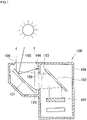
- the head up display device 100 shown in Fig. 1 is a primary improvement type device, and is different from the device described in Patent Literature 2 in that between the concave mirror 101 and the plane mirror 102, the shielding plate 104 and the shielding plate 105 were extended to the very vicinity of the optical path 103.
- the sunlight 106 is reflected by the concave mirror 101, hits the shielding plate 104, stops, and there is no fear of reaching the display unit 107.
- the present inventors further advanced the improvement, completed the secondary improved device, and succeeded in taking good sunlight countermeasures. That is, the head up display device 10 shown in Fig. 2 is a basic configuration diagram of the secondary improvement device according to the invention.
- the head up display device 10 comprises a display unit 13 disposed above the light source 11 for emitting the display light 12, a first concave mirror 14 as a first mirror for reflecting the display light 12 emitted from the display unit 13, a second concave mirror 16 as a second mirror for reflecting the display light 15 reflected by the first concave mirror 14, a light source 11, a display unit 13, and a case 20 for housing the first and second concave mirrors 14, 16.
- the first concave mirror 14 has a curvature (reciprocal of the radius) that causes the reflected display light 15 to cross up and down before reaching the second concave mirror 16, and the second concave mirror 16 reflects the received display light. That is, the first concave mirror 14 has a curvature such that the focal point of the first concave mirror 14 is located between the first concave mirror 14 and the second concave mirror 16. In other words, the distance from the first concave mirror 14 to the second concave mirror 16 is set to be longer than the focal length of the first concave mirror 14.
- the case 20 includes a first shielding portion 23 and a second shielding portion 24 extending to the vicinity of the cross point 22 to sandwich the optical path 21 between the first and second concave mirrors 14, 16.
- the first and second shielding portions 23 and 24 can block external light 25 entering the case 20 from the outside of the case 20 and proceeding toward the first concave mirror 14 after being reflected by the second concave mirror 16.
- the lower end (distal end portion) of the first shielding portion 23 is positioned on the cross point 22 side (lower side) than the line segment L 1 connecting at least the upper end portion P 1 of the reflection region of the display light 12 in the first concave mirror 14 and the upper end portion P 2 of the reflection region of the display light 15 in the second concave mirror 16.
- the upper end (distal end portion) of the second shielding portion 24 is positioned on the cross point 22 side (upper side) than the line segment L 2 connecting at least the lower end portion P 3 of the reflection region of the display light 12 in the first concave mirror 14 and the lower end portion P 4 of the reflection region of the display light 15 in the second concave mirror 16.
- first and second shielding portions 23 and 24 extend so that the tips thereof approach each other.
- the shielding property of the external light 25 is higher as the tips thereof are closer to each other, which is desirable. That is, it is desirable that the tip ends of the two are close to the cross point 22 (focal point).
- the end portion of the reflection region corresponds to the end portion of the concave mirror surface. If a masking tape or the like is provided on the mirror surface, the end portion of the exposed portion of the mirror surface can be regarded as the end portion of the reflection region.
- first and second shielding portions 23 and 24 serve to shield the external light, the temperature thereof rises higher than other portions of the case 20 (a portion distant from the shielding portions 23 and 24, for example, a bottom portion, hereinafter referred to as a general portion 26). Therefore, it is desired that the first and second shielding portions 23 and 24 have higher heat resistance than the general portion 26 of the case 20.
- Table 1 Case general portion First/second shielding portions Combination example 1 ABS resin (110 °C) PC resin (150 °C) Combination example 2 PP resin (168 °C) Epoxy resin (180 °C) Combination example 3 PC resin (150 °C) Aluminum die-cast (580 °C) ( ) Heat resistant temperature (reference value)
- melting temperature is described as a reference value of the heat resistant temperature.
- the heat resistant temperature is shown only for the epoxy resin that is a thermosetting resin.
- the first and second shielding portions 23, 24 are aluminum die-cast products, but the aluminum die-cast product is integrated into the general portion 26 of the case 20 by insert molding, adhesion, screwing or equivalent bonding method.
- the thermal conductivity may be increased.
- heat transfer is promoted, and as a result, the temperatures of the first and second shielding portions 23 and 24 are lowered.
- the strength of the first and second shielding portions 23 and 24 against heat can be increased.
- anti-reflection treated films 27 and 27 for weakening or blocking the reflection of external light are formed at least in the portion where external light 25 strikes the first and second shielding portions 23 and 24.
- the anti-reflection treated film 27 is preferably a black paint, and black alumite is suitable if the base material is aluminum.
- the anti-reflection treatment may be a treatment of roughening by applying sandblast to a smooth surface.
- the invention according to claim 1 is characterized by comprising a display unit 13 for emitting display light 12, a first mirror 14 for reflecting the display light 12 emitted from the display unit 13, a second mirror 16 for reflecting display light 15 reflected by the first mirror 14, and a case 20 for housing the display unit 13 and the first and second mirrors 14, 16, wherein the first mirror 14 is a first concave mirror having a curvature that causes the reflected display light 15 to cross up and down before reaching the second mirror 16, the second mirror 16 is a second concave mirror that reflects the received display light, the case 20 includes a first shielding portion 23 and a second shielding portion 24 extending to the vicinity of the cross point 22 to sandwich the optical path 21 between the first and second concave mirrors, and wherein the first and second shielding portions 23 and 24 can shield external light 25 entering to inside the case 20 from the outside of the case 20 and proceeding toward the first concave mirror after being reflected by the second concave mirror.
- the first mirror is a first concave mirror having a curvature that causes the reflected display light to cross up and down before reaching the second mirror.
- the first shielding portion and the second shielding portion are extended to the vicinity of the crossing point such that external light such as sunlight is shielded by the first shielding portion and the second shielding portion. Most of the external light is shielded by the first and second shielding portions, and cannot reach the first concave mirror or the display. Therefore, according to the present invention, there is provided a head up display device capable of taking measures against sunlight without using a shutter or a reflection type polarizing film.
- the first and second shielding portions are formed of a material having a thermal conductivity higher than that of the general portion of the case. Since the thermal conductivity is high, heat transfer in the first and second shielding portions can be promoted, and the temperature of the first and second shielding portions can be lowered. That is, it is possible to suppress the heat from remaining in the first and second shielding portions, which tend to have a high temperature.
- the first and second shielding portions are formed of a material having a higher heat resistance temperature than that of the general portion of the case.
- a material having a high heat resistant temperature for the first and second shielding portions, which tend to have a high temperature, the strength against heat can be enhanced.
- the first and second shielding portions are subjected to antireflection treatment for weakening or preventing reflection of external light at least at a portion to which external light hits. There is no concern that external light hitting the first and second shielding portions returns to the second concave mirror.
- the case comprises a center frame supporting the first and second concave mirrors and having a second shielding portion; an upper cover attached to the upper side of the center frame and provided with a first shielding portion; and a lower cover attached to the lower side of the center frame.
- the first concave mirror and the second concave mirror are attached to separate covers, it is necessary to adjust the optical axis in consideration of dimensional errors of the individual covers, which makes this adjustment troublesome.
- the first concave mirror and the second concave mirror are attached to the common center frame, adjustment of the optical axes of the first concave mirror and the second concave mirror becomes easy.
- the center frame is a metal molded product
- the lower cover is a resin molded product
- the upper cover is a resin molded product or a metal molded product. If it is a metal molded product, it is rich in rigidity. Since the first and second concave mirrors are attached to the center frame rich in rigidity, the optical axis is favorably maintained.
- metal molded products generally have higher heat resistance temperature and higher thermal conductivity than resin molded products.
- the metal molded product is an aluminum die-cast product.
- the metal molded product may be a metal pressed product, but pressed products cannot be complicated in shape. If it is a cast product, it can be made into a complicated shape, but thinning is difficult. In this respect, if it is a die-cast product, the structure becomes dense, it can be thinned, and it is suitable also for a complicated shape.
- aluminum is lightweight, and the weight saving of the device can be achieved.
- a metal plate is disposed on the upper surface of the first shielding portion that is a resin molded product.
- the first shielding portion is a portion for shielding external light traveling into the case. That is, the upper surface of the first shielding portion is exposed to external light.
- external light striking the first shielding portion sunlight can be mentioned.
- High heat resistance is required for the first shielding portion to which sunlight impinges.
- the head up display device it is desirable that the head up display device as a whole be lightweight.
- the resin used for the upper cover has a smaller (lower) density than the metal plate. For this reason, by making the upper cover a resin molded product, it is possible to reduce the weight of the head up display device.
- the metal plate has higher heat resistance temperature (heat resistance) than the resin used for the upper cover. Therefore, by disposing a metal plate on the upper surface of the first shielding portion to which sunlight impinges, heat resistance can be enhanced. That is, it is possible to increase the heat resistance of the first shielding portion while reducing the weight of the head up display device.
- the case 20 includes a center frame 30 supporting the first and second concave mirrors 14, 16 and having a second shielding portion 24, an upper cover 50 attached to the upper side of the center frame 30 and having a first shielding portion 23, and a lower cover 55 attached to the lower side of the center frame 30.
- the center frame 30 is an aluminum die-cast product having the mounting flanges 31, 31 on its outer periphery and the second shielding portion 24 extending obliquely upward in the interior.
- a stay 32 is welded to the center frame 30, and the first concave mirror 14 is fixed to the stay 32 with the adhesive layer 33.
- the second concave mirror 16 is fixed to the stays 34 to 36 welded to the inner surface of the center frame 30 with adhesive layers 37 to 39.
- the stay 41 extends from the lower part of the center frame 30. Meanwhile, the light source 11 and the display unit 13 are fitted to the tubular bracket 42, and the bracket piece 43 extended from the tubular bracket 42 is fixed to the stay 41 with the screws 44, 44.
- the center frame 30 has a much higher strength and rigidity than the resin molded product if it is an aluminum die-cast product. Since the first and second concave mirrors 14 and 16 and the display unit 13 are collectively attached to the center frame 30 rich in rigidity, these optical axis adjustments become difficult to deviate. Further, the center frame 30 rich in rigidity is attached to the vehicle by the mounting flanges 31, 31. When the cover is made of resin as a whole, the rigidity becomes insufficient and readjustment of the optical axis may be necessary. On the other hand, since the head up display device 10 of the embodiment is rich in rigidity, there is little concern.
- the upper cover 50 is, for example, a polycarbonate molded product, and has a cover glass 51 on its upper surface, and integrally includes a first shielding portion 23 extending obliquely downward.
- the lower cover 55 is a bottomed cylindrical body that opens upward, and is, for example, an ABS resin molded product, and incorporates a printed board 56 therein.
- the lower cover 55 is attached to the center frame 30 from the bottom with screws 57, 57, and the upper cover 50 is attached with screws 52 from the top.
- the head up display device 10 shown in Fig. 4 is completed.
- the display light 12 emitted from the display unit 13 is reflected by the first concave mirror 14, and the display light 15 reflected by the first concave mirror 14 passes between the first and second shielding portions 23 and 24, and reaches the second concave mirror 16.
- the display light 17 reflected by the second concave mirror 16 rises and reaches the windshield 66 of the vehicle (the projection part 66 on which the reflected display light 17 is projected).
- the first shielding portion 23 is polycarbonate excellent in heat resistance, it has high strength against heat.
- the external light 25 passes through the cover glass 51, is reflected by the second concave mirror 16, and is shielded by the second shielding portion 24. Since the second shielding portion 24 is aluminum excellent in heat resistance, the second shielding portion 24 has higher strength against heat.
- PC resin has thermal conductivity of about 0.2 W/m /K.
- ADC 12 aluminum die-cast product has a thermal conductivity of about 100 W/m/K.
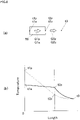
- Fig. 6 (a) is a diagram for explaining a very simple heat transfer model. It is assumed that one end of a rod 59 made of polycarbonate (PC) resin has a high temperature t1p, a temperature lower than t1p at the other end (t2p is higher than the atmospheric temperature t3), and in a thermally steady state. Assuming that the outer periphery of the rod 59 is thermally insulated, the heat Q1p flowing inside the rod 59 and the heat Q2p discharged from the other end of the rod 59 to the atmosphere are equal.
- PC polycarbonate
- Q1p is calculated by the thermal conductivity ⁇ p ⁇ the length of the bar ⁇ (t1p - t2p). Further, Q2p is calculated by the heat transfer coefficient cp ⁇ (t2p - t3).
- one end of a rod 59 of an aluminum die-cast product is assumed to be thermally steady at a high temperature tla, a temperature lower than t2a at the other end (t2a is higher than the atmospheric temperature t3), and in a thermally steady state.
- the outer periphery of the rod 59 is thermally insulated, the heat Q1a flowing inside the rod 59 and the heat Q2a discharged from the other end of the rod 59 to the atmosphere are equal.
- the cross-sectional area of the rod is the unit cross-sectional area (1.0)
- Q1a is calculated by the thermal conductivity ⁇ a ⁇ the length of the bar ⁇ (t1a - t2a).
- Q2a is calculated by the heat transfer coefficient ca ⁇ (t2a - t3).
- the first shielding portion 23 is also made of aluminum die-cast or light metal, which is the same as the second shielding portion 24.
- an aluminum die-cast product 63 integrally formed with the heat radiation fin 61 is preliminary manufactured in the first shielding portion 23, the aluminum die-cast product 63 is placed in a cavity of a molding die, and the PC resin 64 is injected into the cavity thereby performing so-called insert molding.
- the heat radiation fin 61 When the first shielding portion 23 is heated by the external light 25, heat propagates through the first shielding portion 23 and reaches the heat radiation fins 61. Since the heat radiation fin 61 has a large heat radiation area, it actively radiates heat towards the atmosphere.
- the whole of the upper cover 50 may be made of aluminum die-cast or light metal.
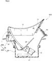
- FIG. 8 shows a sectional configuration of the head up display device of the second embodiment.
- Fig. 8 corresponds to Fig. 4 above.
- the metal plate 71 is disposed on the upper surface of the first shielding portion 23.
- the other basic configuration is common to the head up display device 10 (see Fig. 4 ) according to the first embodiment.
- reference numerals are used, and detailed description is omitted.
- the upper cover 50A is a resin molded product, and for example, a mixed resin material of polycarbonate and polyethylene terephthalate (PET) can be used.
- PET polyethylene terephthalate
- the material of the metal plate 71 aluminum or an aluminum alloy can be used.
- the resin as the material of the resin molded product is smaller than the density of the metal used for the metal plate 71.
- the heat resistant temperature of the resin used for the material is lower than the heat resistant temperature of the metal used for the metal plate 71. That is, the heat resistant temperature of the metal plate 71 is higher than the heat resistant temperature of the resin. As long as these conditions are satisfied, any material can be selected for resin or metal.
- Three metal plates 71 are attached to the upper cover 50A.
- the metal plates 71 are respectively attached to the upper surface of the first shielding portion 23, and the inner surfaces of the left and right side surfaces of the upper cover 50A extending forward from and the left and right end portions of the upper surface. These can be said to be design surfaces visible from the outside. That is, the metal plate 71 is arranged on the design surface. By placing the metal plate 71 on the visually recognizable part, it is possible to further improve the design.
- the metal plate 71 can be disposed on the upper cover 50A by an arbitrary method such as sticking with a double-sided tape, adhesion with an adhesive, screwing using a screw, locking using a fixing hook, or the like.
- a metal plate 71 is disposed on the upper surface of the first shielding portion 23 that is a resin molded product.
- the first shielding portion 23 is a portion for blocking external light traveling into the case 20A. That is, the upper surface of the first shielding portion 23 is exposed to external light.
- external light striking the first shielding portion 23 sunlight can be mentioned.
- High heat resistance is required for the first shielding portion 23 against which sunlight impinges.
- the head up display device 10A as a whole be lightweight.
- the density of the resin used for the upper cover 50A is smaller (lower) than that of the metal plate 71.
- the metal plate 71 has higher heat resistance temperature (heat resistance) than the resin used for the upper cover 50A. Therefore, by arranging the metal plate 71 on the upper surface of the first shielding portion 23 to which sunlight impinges, the heat resistance can be enhanced. That is, it is possible to increase the heat resistance of the first shielding portion 23 while reducing the weight of the head up display device 10A.
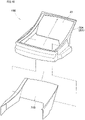
- Fig. 10 shows a modified example of the head up display device 10B in which the metal plate 71B is changed. That is, the metal plate 71B can also be constituted by a single plate. Even in this case, the predetermined effect of the present invention can be obtained. In addition, in the case of a single plate, there is no joint between the metal plates compared with the case where it is constituted by a plurality of plates, and the design can be further enhanced.
- the head up display device of the present invention is suitable for passenger cars, it may be applied to general vehicles, ships and aircraft. That is, the present invention is not limited to the examples as long as the effects and advantages of the present invention are exhibited.
- the head up display device of the present invention is suitable for a vehicle having a windshield.
Landscapes
- Engineering & Computer Science (AREA)
- Physics & Mathematics (AREA)
- Chemical & Material Sciences (AREA)
- Combustion & Propulsion (AREA)
- Transportation (AREA)
- Mechanical Engineering (AREA)
- General Physics & Mathematics (AREA)
- Optics & Photonics (AREA)
- Instrument Panels (AREA)
Claims (8)
- Frontscheibenanzeigevorrichtung, umfassend eine Anzeigeeinheit (13) zum Ausstrahlen von Anzeigelicht (12), einen ersten Spiegel (14) zum Reflektieren des Anzeigelichts (12), das von der Anzeigeeinheit (13) ausgestrahlt wird, einen zweiten Spiegel (16) zum Reflektieren von Anzeigelicht (15), das von dem ersten Spiegel (14) reflektiert wird, und ein Gehäuse (20, 20A) zum Unterbringen der Anzeigeeinheit (13) und des ersten und des zweiten Spiegels (14, 16), wobei:der erste Spiegel (14) ein erster konkaver Spiegel mit einer Krümmung ist, die bewirk, dass das reflektierte Anzeigelicht (15) auf- und abwärts kreuzt, bevor es den zweiten Spiegel (16) erreicht,der zweite Spiegel (16) ein zweiter konkaver Spiegel ist, der das empfangene Anzeigelicht (15) reflektiert,das Gehäuse (20, 20A) einen ersten Abschirmungsabschnitt (23) und einen zweiten Abschirmungsabschnitt (24) beinhaltet, die sich in der Nähe eines Kreuzungspunktes (22) erstrecken, um einen optischen Weg zwischen dem ersten und dem zweiten konkaven Spiegel (14, 16) einzuschließen, undder erste und der zweite Abschirmungsabschnitt (23, 24) externes Licht (25) abschirmen, das von außerhalb des Gehäuses (20, 20A) in das Innere des Gehäuses (20, 20A) eintritt und sich hin zu dem ersten konkaven Spiegel (14) fortpflanzt, nachdem es von dem zweiten konkaven Spiegel (16) reflektiert wurde.
- Frontscheibenanzeigevorrichtung nach Anspruch 1, wobei der erste und der zweite Abschirmungsabschnitt (23, 24) aus einem Material bestehen, das ein höheres Wärmeleitvermögen als ein allgemeiner Abschnitt (26) des Gehäuses (20, 20A) aufweist.
- Frontscheibenanzeigevorrichtung nach Anspruch 1, wobei der erste und der zweite Abschirmungsabschnitt (23, 24) aus einem Material bestehen, das eine höhere Hitzebeständigkeitstemperatur als ein allgemeiner Abschnitt (26) des Gehäuses (20, 20A) aufweist.
- Frontscheibenanzeigevorrichtung nach Anspruch 1, wobei auf mindestens einen Abschnitt des ersten und des zweiten Abschirmungsabschnitts (23, 24), auf den das externe Licht (25) auftrifft, eine Antireflexionsbehandlung zum Abschwächen oder Verhindern der Reflexion externen Lichts (25) angewandt wurde.
- Frontscheibenanzeigevorrichtung nach Anspruch 1, wobei
das Gehäuse (20, 20A) Folgendes umfasst:einen Mittelrahmen (30), der den ersten und den zweiten konkaven Spiegel (14, 16) trägt und den zweiten Abschirmungsabschnitt (24) beinhaltet,eine obere Abdeckung (50, 50A), die an einer Oberseite des Mittelrahmens (30) angebracht und mit dem ersten Abschirmungsabschnitt (23) versehen ist, undeine untere Abdeckung (55), die an einer Unterseite des Mittelrahmens (30) angebracht ist. - Frontscheibenanzeigevorrichtung nach Anspruch 5, wobei der Mittelrahmen (30) ein Metallformprodukt ist,
die untere Abdeckung (55) ein Harzformprodukt ist und die obere Abdeckung (50, 50A) ein Harzformprodukt oder ein Metallformprodukt ist. - Frontscheibenanzeigevorrichtung nach Anspruch 6, wobei das Metallformprodukt ein Aluminiumdruckgussprodukt ist.
- Frontscheibenanzeigevorrichtung nach Anspruch 1, wobei:das Gehäuse (20A) einen Mittelrahmen (30) umfasst, der den ersten und den zweiten konkaven Spiegel (14, 16) trägt und den zweiten Abschirmungsabschnitt (24) beinhaltet, und eine obere Abdeckung (50A), die an einer Oberseite des Mittelrahmens (30) angebracht und mit dem ersten Abschirmungsabschnitt (23) versehen ist,die obere Abdeckung (50A) ein Harzformprodukt isteine Metallplatte (71) mindestens an der oberen Oberfläche des ersten Abschirmungsabschnitts (23) angeordnet ist,die Dichte des Harzes, das für das Material des Harzformprodukts verwendet wird, kleiner als die Dichte der Metallplatte (71) ist unddie Hitzebeständigkeitstemperatur der Metallplatte (71) höher als die Hitzebeständigkeitstemperatur des Harzes ist.
Applications Claiming Priority (3)
| Application Number | Priority Date | Filing Date | Title |
|---|---|---|---|
| JP2014229919 | 2014-11-12 | ||
| JP2015212180A JP6579319B2 (ja) | 2014-11-12 | 2015-10-28 | ヘッドアップディスプレイ装置 |
| PCT/JP2015/081683 WO2016076342A1 (ja) | 2014-11-12 | 2015-11-11 | ヘッドアップディスプレイ装置 |
Publications (3)
| Publication Number | Publication Date |
|---|---|
| EP3220186A1 EP3220186A1 (de) | 2017-09-20 |
| EP3220186A4 EP3220186A4 (de) | 2018-10-24 |
| EP3220186B1 true EP3220186B1 (de) | 2022-10-19 |
Family
ID=56089460
Family Applications (1)
| Application Number | Title | Priority Date | Filing Date |
|---|---|---|---|
| EP15858147.0A Active EP3220186B1 (de) | 2014-11-12 | 2015-11-11 | Head-up-display-vorrichtung |
Country Status (4)
| Country | Link |
|---|---|
| US (1) | US10114218B2 (de) |
| EP (1) | EP3220186B1 (de) |
| JP (1) | JP6579319B2 (de) |
| CN (1) | CN107111133A (de) |
Families Citing this family (28)
| Publication number | Priority date | Publication date | Assignee | Title |
|---|---|---|---|---|
| FR3050039B1 (fr) * | 2016-04-12 | 2021-11-19 | Valeo Comfort & Driving Assistance | Afficheur tete haute |
| WO2017195740A1 (ja) * | 2016-05-09 | 2017-11-16 | 日本精機株式会社 | ヘッドアップディスプレイ装置 |
| CN109477968B (zh) * | 2016-07-07 | 2021-08-13 | 麦克赛尔株式会社 | 平视显示装置 |
| JP6963732B2 (ja) * | 2016-09-30 | 2021-11-10 | 日本精機株式会社 | ヘッドアップディスプレイ装置 |
| US11226484B2 (en) | 2016-10-26 | 2022-01-18 | Nippon Seiki Co., Ltd. | Head-up display device |
| WO2018198821A1 (ja) * | 2017-04-27 | 2018-11-01 | 日本精機株式会社 | ヘッドアップディスプレイ装置 |
| JP6876932B2 (ja) * | 2017-06-20 | 2021-05-26 | パナソニックIpマネジメント株式会社 | 画像表示装置 |
| JP6864574B2 (ja) * | 2017-07-04 | 2021-04-28 | 株式会社ホンダロック | 車両用周辺表示装置 |
| JP2019028137A (ja) * | 2017-07-26 | 2019-02-21 | 矢崎総業株式会社 | 車両用表示装置 |
| JP7037760B2 (ja) * | 2018-03-16 | 2022-03-17 | 株式会社リコー | 画像投写装置及び移動体 |
| CN108594442A (zh) * | 2018-06-19 | 2018-09-28 | 惠州市华阳多媒体电子有限公司 | 一种减少tft太阳光害的hud光路系统 |
| JP7173768B2 (ja) | 2018-07-04 | 2022-11-16 | キヤノン株式会社 | 電子ビューファインダおよび撮像装置 |
| WO2020026865A1 (ja) * | 2018-07-30 | 2020-02-06 | 日本精機株式会社 | ヘッドアップディスプレイ装置 |
| WO2020080384A1 (ja) * | 2018-10-16 | 2020-04-23 | 日本精機株式会社 | ヘッドアップディスプレイ装置 |
| EP3899643B1 (de) | 2018-12-21 | 2023-01-25 | 3M Innovative Properties Company | Kompakte head-up-anzeige |
| WO2020243939A1 (en) | 2019-06-06 | 2020-12-10 | 3M Innovative Properties Company | Compact heads-up display |
| US12325302B2 (en) * | 2019-10-21 | 2025-06-10 | Maxell, Ltd. | Light source apparatus, and information display system and head-up display apparatus using the same |
| WO2021230277A1 (ja) * | 2020-05-14 | 2021-11-18 | 日本精機株式会社 | ヘッドアップディスプレイ装置 |
| JP7435337B2 (ja) * | 2020-07-27 | 2024-02-21 | 株式会社デンソー | カバー部材 |
| JP7163344B2 (ja) * | 2020-09-08 | 2022-10-31 | 矢崎総業株式会社 | 車両用表示装置 |
| DE102021106972B4 (de) | 2021-03-22 | 2024-02-08 | Dr. Ing. H.C. F. Porsche Aktiengesellschaft | Head-Up-Display für ein Kraftfahrzeug sowie Kraftfahrzeug mit diesem |
| DE102021203930A1 (de) * | 2021-04-20 | 2022-10-20 | Continental Automotive Technologies GmbH | Spiegel für ein Head-Up-Display |
| WO2023063084A1 (ja) * | 2021-10-11 | 2023-04-20 | 株式会社小糸製作所 | 画像照射装置、画像照射装置の制御方法、画像生成装置、ヘッドアップディスプレイ及びカバー |
| CN116520572A (zh) * | 2022-01-28 | 2023-08-01 | 佳能株式会社 | 光学构件、光学设备、成像装置和显示装置 |
| CN117908251A (zh) * | 2022-10-11 | 2024-04-19 | 华为技术有限公司 | 显示装置和交通工具 |
| FR3144317A1 (fr) * | 2022-12-23 | 2024-06-28 | Valeo Comfort And Driving Assistance | Dispositif de génération d’images et afficheur tête haute comportant un tel dispositif |
| KR102898531B1 (ko) * | 2023-07-19 | 2025-12-10 | 주식회사 티앤에프글로벌 | 차량에 장착되는 헤드 업 디스플레이 및 이를 제조하는 공정 시스템 |
| DE102024119689A1 (de) * | 2024-07-11 | 2026-01-15 | Valeo Schalter Und Sensoren Gmbh | Verfahren zum Herstellen eines Spiegels für ein Head-up-Display, optisches Abbildungselement, sowie Head-up-Display |
Family Cites Families (14)
| Publication number | Priority date | Publication date | Assignee | Title |
|---|---|---|---|---|
| DE233003T1 (de) * | 1986-01-29 | 1988-03-17 | Pilkington Brothers P.L.C., St. Helens, Merseyside | Beschichtetes glas. |
| JPS62275845A (ja) * | 1986-05-23 | 1987-11-30 | Nissan Motor Co Ltd | 車両用表示装置 |
| JPH0628993B2 (ja) * | 1986-05-23 | 1994-04-20 | 日産自動車株式会社 | 車両用表示装置 |
| JPH04242785A (ja) * | 1990-12-28 | 1992-08-31 | Shimadzu Corp | ヘッドアップディスプレイ |
| JP3321849B2 (ja) * | 1991-10-09 | 2002-09-09 | 株式会社デンソー | ホログラム |
| EP0536763B1 (de) * | 1991-10-09 | 1999-03-17 | Denso Corporation | Hologramm |
| JPH09159986A (ja) * | 1995-12-13 | 1997-06-20 | Kansei Corp | 車両用情報表示装置 |
| JP4114194B2 (ja) | 1998-10-29 | 2008-07-09 | 日本精機株式会社 | ヘッドアップディスプレイ装置 |
| JP2003237411A (ja) | 2002-02-12 | 2003-08-27 | Denso Corp | ヘッドアップディスプレイ装置 |
| JP2004226469A (ja) * | 2003-01-20 | 2004-08-12 | Denso Corp | 車両用ヘッドアップディスプレイ装置 |
| JP4739149B2 (ja) * | 2006-08-29 | 2011-08-03 | 矢崎総業株式会社 | 表示装置 |
| DE102011075205A1 (de) * | 2011-05-04 | 2012-11-08 | Robert Bosch Gmbh | Anzeigevorrichtung für ein Fahrzeug, Fahrzeug mit einer Anzeigevorrichtung sowie Verfahren zum Anzeigen einer Bildinformation |
| JP5873707B2 (ja) * | 2011-12-15 | 2016-03-01 | 矢崎総業株式会社 | ヘッドアップディスプレイ装置 |
| JP6004706B2 (ja) * | 2012-04-04 | 2016-10-12 | 三菱電機株式会社 | 表示装置及びこれを備えたヘッドアップディスプレイシステム |
-
2015
- 2015-10-28 JP JP2015212180A patent/JP6579319B2/ja active Active
- 2015-11-11 CN CN201580061256.6A patent/CN107111133A/zh active Pending
- 2015-11-11 EP EP15858147.0A patent/EP3220186B1/de active Active
- 2015-11-11 US US15/526,078 patent/US10114218B2/en active Active
Also Published As
| Publication number | Publication date |
|---|---|
| JP2016103008A (ja) | 2016-06-02 |
| JP6579319B2 (ja) | 2019-09-25 |
| CN107111133A (zh) | 2017-08-29 |
| US10114218B2 (en) | 2018-10-30 |
| EP3220186A1 (de) | 2017-09-20 |
| US20170315351A1 (en) | 2017-11-02 |
| EP3220186A4 (de) | 2018-10-24 |
Similar Documents
| Publication | Publication Date | Title |
|---|---|---|
| EP3220186B1 (de) | Head-up-display-vorrichtung | |
| JP6769481B2 (ja) | ヘッドアップディスプレイ装置 | |
| JP6642172B2 (ja) | ヘッドアップディスプレイ装置 | |
| US20190146217A1 (en) | Head-up display device | |
| JP6563711B2 (ja) | ヘッドアップディスプレイ装置 | |
| US11061227B2 (en) | Display device and apparatus | |
| US10513168B2 (en) | Vehicular optical system | |
| JP2017049371A (ja) | ヘッドアップディスプレイ装置 | |
| JP7115471B2 (ja) | ヘッドアップディスプレイ装置 | |
| WO2016076342A1 (ja) | ヘッドアップディスプレイ装置 | |
| JP2017187528A (ja) | ヘッドアップディスプレイ装置 | |
| US10746904B2 (en) | Free-form surface lens, method of designing free-form surface lens, free-form surface mirror, method of designing free-form surface mirror, and projection type video display apparatus | |
| US11693222B2 (en) | Reflective optical element and stereo camera device | |
| KR20190107730A (ko) | 광학 포착 장치의 발광 유닛을 위한 광학 소자, 발광 유닛, 광학 포착 장치, 자동차, 및 방법 | |
| CN114660817B (zh) | 抬头显示器、交通工具及抬头显示方法 | |
| JP2019162929A (ja) | 車両用センサ装置 | |
| WO2019193860A1 (ja) | 撮影装置 | |
| JP2018054861A (ja) | 撮像装置及び移動体 | |
| JP2019185012A (ja) | 撮影装置 | |
| CN114994815A (zh) | 反射光学元件和立体相机装置 |
Legal Events
| Date | Code | Title | Description |
|---|---|---|---|
| STAA | Information on the status of an ep patent application or granted ep patent |
Free format text: STATUS: THE INTERNATIONAL PUBLICATION HAS BEEN MADE |
|
| PUAI | Public reference made under article 153(3) epc to a published international application that has entered the european phase |
Free format text: ORIGINAL CODE: 0009012 |
|
| STAA | Information on the status of an ep patent application or granted ep patent |
Free format text: STATUS: REQUEST FOR EXAMINATION WAS MADE |
|
| 17P | Request for examination filed |
Effective date: 20170608 |
|
| AK | Designated contracting states |
Kind code of ref document: A1 Designated state(s): AL AT BE BG CH CY CZ DE DK EE ES FI FR GB GR HR HU IE IS IT LI LT LU LV MC MK MT NL NO PL PT RO RS SE SI SK SM TR |
|
| AX | Request for extension of the european patent |
Extension state: BA ME |
|
| DAV | Request for validation of the european patent (deleted) | ||
| DAX | Request for extension of the european patent (deleted) | ||
| RIC1 | Information provided on ipc code assigned before grant |
Ipc: B60K 35/00 20060101ALI20180614BHEP Ipc: G02B 27/01 20060101AFI20180614BHEP |
|
| A4 | Supplementary search report drawn up and despatched |
Effective date: 20180921 |
|
| RIC1 | Information provided on ipc code assigned before grant |
Ipc: G02B 27/01 20060101AFI20180917BHEP Ipc: B60K 35/00 20060101ALI20180917BHEP |
|
| GRAP | Despatch of communication of intention to grant a patent |
Free format text: ORIGINAL CODE: EPIDOSNIGR1 |
|
| STAA | Information on the status of an ep patent application or granted ep patent |
Free format text: STATUS: GRANT OF PATENT IS INTENDED |
|
| RIC1 | Information provided on ipc code assigned before grant |
Ipc: G02B 5/30 20060101ALI20220211BHEP Ipc: B60K 35/00 20060101ALI20220211BHEP Ipc: G02B 27/01 20060101AFI20220211BHEP |
|
| INTG | Intention to grant announced |
Effective date: 20220309 |
|
| GRAJ | Information related to disapproval of communication of intention to grant by the applicant or resumption of examination proceedings by the epo deleted |
Free format text: ORIGINAL CODE: EPIDOSDIGR1 |
|
| STAA | Information on the status of an ep patent application or granted ep patent |
Free format text: STATUS: REQUEST FOR EXAMINATION WAS MADE |
|
| GRAP | Despatch of communication of intention to grant a patent |
Free format text: ORIGINAL CODE: EPIDOSNIGR1 |
|
| STAA | Information on the status of an ep patent application or granted ep patent |
Free format text: STATUS: GRANT OF PATENT IS INTENDED |
|
| INTC | Intention to grant announced (deleted) | ||
| INTG | Intention to grant announced |
Effective date: 20220804 |
|
| GRAS | Grant fee paid |
Free format text: ORIGINAL CODE: EPIDOSNIGR3 |
|
| GRAA | (expected) grant |
Free format text: ORIGINAL CODE: 0009210 |
|
| STAA | Information on the status of an ep patent application or granted ep patent |
Free format text: STATUS: THE PATENT HAS BEEN GRANTED |
|
| AK | Designated contracting states |
Kind code of ref document: B1 Designated state(s): AL AT BE BG CH CY CZ DE DK EE ES FI FR GB GR HR HU IE IS IT LI LT LU LV MC MK MT NL NO PL PT RO RS SE SI SK SM TR |
|
| REG | Reference to a national code |
Ref country code: GB Ref legal event code: FG4D |
|
| REG | Reference to a national code |
Ref country code: CH Ref legal event code: EP |
|
| REG | Reference to a national code |
Ref country code: IE Ref legal event code: FG4D |
|
| REG | Reference to a national code |
Ref country code: DE Ref legal event code: R096 Ref document number: 602015081264 Country of ref document: DE |
|
| REG | Reference to a national code |
Ref country code: AT Ref legal event code: REF Ref document number: 1525911 Country of ref document: AT Kind code of ref document: T Effective date: 20221115 |
|
| REG | Reference to a national code |
Ref country code: LT Ref legal event code: MG9D |
|
| REG | Reference to a national code |
Ref country code: NL Ref legal event code: MP Effective date: 20221019 |
|
| REG | Reference to a national code |
Ref country code: AT Ref legal event code: MK05 Ref document number: 1525911 Country of ref document: AT Kind code of ref document: T Effective date: 20221019 |
|
| PG25 | Lapsed in a contracting state [announced via postgrant information from national office to epo] |
Ref country code: NL Free format text: LAPSE BECAUSE OF FAILURE TO SUBMIT A TRANSLATION OF THE DESCRIPTION OR TO PAY THE FEE WITHIN THE PRESCRIBED TIME-LIMIT Effective date: 20221019 |
|
| PG25 | Lapsed in a contracting state [announced via postgrant information from national office to epo] |
Ref country code: SE Free format text: LAPSE BECAUSE OF FAILURE TO SUBMIT A TRANSLATION OF THE DESCRIPTION OR TO PAY THE FEE WITHIN THE PRESCRIBED TIME-LIMIT Effective date: 20221019 Ref country code: PT Free format text: LAPSE BECAUSE OF FAILURE TO SUBMIT A TRANSLATION OF THE DESCRIPTION OR TO PAY THE FEE WITHIN THE PRESCRIBED TIME-LIMIT Effective date: 20230220 Ref country code: NO Free format text: LAPSE BECAUSE OF FAILURE TO SUBMIT A TRANSLATION OF THE DESCRIPTION OR TO PAY THE FEE WITHIN THE PRESCRIBED TIME-LIMIT Effective date: 20230119 Ref country code: LT Free format text: LAPSE BECAUSE OF FAILURE TO SUBMIT A TRANSLATION OF THE DESCRIPTION OR TO PAY THE FEE WITHIN THE PRESCRIBED TIME-LIMIT Effective date: 20221019 Ref country code: FI Free format text: LAPSE BECAUSE OF FAILURE TO SUBMIT A TRANSLATION OF THE DESCRIPTION OR TO PAY THE FEE WITHIN THE PRESCRIBED TIME-LIMIT Effective date: 20221019 Ref country code: ES Free format text: LAPSE BECAUSE OF FAILURE TO SUBMIT A TRANSLATION OF THE DESCRIPTION OR TO PAY THE FEE WITHIN THE PRESCRIBED TIME-LIMIT Effective date: 20221019 Ref country code: AT Free format text: LAPSE BECAUSE OF FAILURE TO SUBMIT A TRANSLATION OF THE DESCRIPTION OR TO PAY THE FEE WITHIN THE PRESCRIBED TIME-LIMIT Effective date: 20221019 |
|
| PG25 | Lapsed in a contracting state [announced via postgrant information from national office to epo] |
Ref country code: RS Free format text: LAPSE BECAUSE OF FAILURE TO SUBMIT A TRANSLATION OF THE DESCRIPTION OR TO PAY THE FEE WITHIN THE PRESCRIBED TIME-LIMIT Effective date: 20221019 Ref country code: PL Free format text: LAPSE BECAUSE OF FAILURE TO SUBMIT A TRANSLATION OF THE DESCRIPTION OR TO PAY THE FEE WITHIN THE PRESCRIBED TIME-LIMIT Effective date: 20221019 Ref country code: LV Free format text: LAPSE BECAUSE OF FAILURE TO SUBMIT A TRANSLATION OF THE DESCRIPTION OR TO PAY THE FEE WITHIN THE PRESCRIBED TIME-LIMIT Effective date: 20221019 Ref country code: IS Free format text: LAPSE BECAUSE OF FAILURE TO SUBMIT A TRANSLATION OF THE DESCRIPTION OR TO PAY THE FEE WITHIN THE PRESCRIBED TIME-LIMIT Effective date: 20230219 Ref country code: HR Free format text: LAPSE BECAUSE OF FAILURE TO SUBMIT A TRANSLATION OF THE DESCRIPTION OR TO PAY THE FEE WITHIN THE PRESCRIBED TIME-LIMIT Effective date: 20221019 Ref country code: GR Free format text: LAPSE BECAUSE OF FAILURE TO SUBMIT A TRANSLATION OF THE DESCRIPTION OR TO PAY THE FEE WITHIN THE PRESCRIBED TIME-LIMIT Effective date: 20230120 |
|
| REG | Reference to a national code |
Ref country code: CH Ref legal event code: PL |
|
| REG | Reference to a national code |
Ref country code: DE Ref legal event code: R097 Ref document number: 602015081264 Country of ref document: DE |
|
| REG | Reference to a national code |
Ref country code: BE Ref legal event code: MM Effective date: 20221130 |
|
| PG25 | Lapsed in a contracting state [announced via postgrant information from national office to epo] |
Ref country code: SM Free format text: LAPSE BECAUSE OF FAILURE TO SUBMIT A TRANSLATION OF THE DESCRIPTION OR TO PAY THE FEE WITHIN THE PRESCRIBED TIME-LIMIT Effective date: 20221019 Ref country code: RO Free format text: LAPSE BECAUSE OF FAILURE TO SUBMIT A TRANSLATION OF THE DESCRIPTION OR TO PAY THE FEE WITHIN THE PRESCRIBED TIME-LIMIT Effective date: 20221019 Ref country code: MC Free format text: LAPSE BECAUSE OF FAILURE TO SUBMIT A TRANSLATION OF THE DESCRIPTION OR TO PAY THE FEE WITHIN THE PRESCRIBED TIME-LIMIT Effective date: 20221019 Ref country code: LI Free format text: LAPSE BECAUSE OF NON-PAYMENT OF DUE FEES Effective date: 20221130 Ref country code: EE Free format text: LAPSE BECAUSE OF FAILURE TO SUBMIT A TRANSLATION OF THE DESCRIPTION OR TO PAY THE FEE WITHIN THE PRESCRIBED TIME-LIMIT Effective date: 20221019 Ref country code: DK Free format text: LAPSE BECAUSE OF FAILURE TO SUBMIT A TRANSLATION OF THE DESCRIPTION OR TO PAY THE FEE WITHIN THE PRESCRIBED TIME-LIMIT Effective date: 20221019 Ref country code: CZ Free format text: LAPSE BECAUSE OF FAILURE TO SUBMIT A TRANSLATION OF THE DESCRIPTION OR TO PAY THE FEE WITHIN THE PRESCRIBED TIME-LIMIT Effective date: 20221019 Ref country code: CH Free format text: LAPSE BECAUSE OF NON-PAYMENT OF DUE FEES Effective date: 20221130 |
|
| PLBE | No opposition filed within time limit |
Free format text: ORIGINAL CODE: 0009261 |
|
| STAA | Information on the status of an ep patent application or granted ep patent |
Free format text: STATUS: NO OPPOSITION FILED WITHIN TIME LIMIT |
|
| PG25 | Lapsed in a contracting state [announced via postgrant information from national office to epo] |
Ref country code: SK Free format text: LAPSE BECAUSE OF FAILURE TO SUBMIT A TRANSLATION OF THE DESCRIPTION OR TO PAY THE FEE WITHIN THE PRESCRIBED TIME-LIMIT Effective date: 20221019 Ref country code: LU Free format text: LAPSE BECAUSE OF NON-PAYMENT OF DUE FEES Effective date: 20221111 Ref country code: AL Free format text: LAPSE BECAUSE OF FAILURE TO SUBMIT A TRANSLATION OF THE DESCRIPTION OR TO PAY THE FEE WITHIN THE PRESCRIBED TIME-LIMIT Effective date: 20221019 |
|
| 26N | No opposition filed |
Effective date: 20230720 |
|
| GBPC | Gb: european patent ceased through non-payment of renewal fee |
Effective date: 20230119 |
|
| PG25 | Lapsed in a contracting state [announced via postgrant information from national office to epo] |
Ref country code: IE Free format text: LAPSE BECAUSE OF NON-PAYMENT OF DUE FEES Effective date: 20221111 Ref country code: GB Free format text: LAPSE BECAUSE OF NON-PAYMENT OF DUE FEES Effective date: 20230119 |
|
| PG25 | Lapsed in a contracting state [announced via postgrant information from national office to epo] |
Ref country code: SI Free format text: LAPSE BECAUSE OF FAILURE TO SUBMIT A TRANSLATION OF THE DESCRIPTION OR TO PAY THE FEE WITHIN THE PRESCRIBED TIME-LIMIT Effective date: 20221019 Ref country code: FR Free format text: LAPSE BECAUSE OF NON-PAYMENT OF DUE FEES Effective date: 20221219 Ref country code: BE Free format text: LAPSE BECAUSE OF NON-PAYMENT OF DUE FEES Effective date: 20221130 |
|
| PG25 | Lapsed in a contracting state [announced via postgrant information from national office to epo] |
Ref country code: HU Free format text: LAPSE BECAUSE OF FAILURE TO SUBMIT A TRANSLATION OF THE DESCRIPTION OR TO PAY THE FEE WITHIN THE PRESCRIBED TIME-LIMIT; INVALID AB INITIO Effective date: 20151111 |
|
| PG25 | Lapsed in a contracting state [announced via postgrant information from national office to epo] |
Ref country code: CY Free format text: LAPSE BECAUSE OF FAILURE TO SUBMIT A TRANSLATION OF THE DESCRIPTION OR TO PAY THE FEE WITHIN THE PRESCRIBED TIME-LIMIT Effective date: 20221019 |
|
| PG25 | Lapsed in a contracting state [announced via postgrant information from national office to epo] |
Ref country code: MK Free format text: LAPSE BECAUSE OF FAILURE TO SUBMIT A TRANSLATION OF THE DESCRIPTION OR TO PAY THE FEE WITHIN THE PRESCRIBED TIME-LIMIT Effective date: 20221019 Ref country code: IT Free format text: LAPSE BECAUSE OF FAILURE TO SUBMIT A TRANSLATION OF THE DESCRIPTION OR TO PAY THE FEE WITHIN THE PRESCRIBED TIME-LIMIT Effective date: 20221019 |
|
| PG25 | Lapsed in a contracting state [announced via postgrant information from national office to epo] |
Ref country code: TR Free format text: LAPSE BECAUSE OF FAILURE TO SUBMIT A TRANSLATION OF THE DESCRIPTION OR TO PAY THE FEE WITHIN THE PRESCRIBED TIME-LIMIT Effective date: 20221019 |
|
| PG25 | Lapsed in a contracting state [announced via postgrant information from national office to epo] |
Ref country code: BG Free format text: LAPSE BECAUSE OF FAILURE TO SUBMIT A TRANSLATION OF THE DESCRIPTION OR TO PAY THE FEE WITHIN THE PRESCRIBED TIME-LIMIT Effective date: 20221019 |
|
| PG25 | Lapsed in a contracting state [announced via postgrant information from national office to epo] |
Ref country code: MT Free format text: LAPSE BECAUSE OF FAILURE TO SUBMIT A TRANSLATION OF THE DESCRIPTION OR TO PAY THE FEE WITHIN THE PRESCRIBED TIME-LIMIT Effective date: 20221019 |
|
| PGFP | Annual fee paid to national office [announced via postgrant information from national office to epo] |
Ref country code: DE Payment date: 20250930 Year of fee payment: 11 |