EP3220221B1 - Essai de dispositifs de sécurité - Google Patents
Essai de dispositifs de sécurité Download PDFInfo
- Publication number
- EP3220221B1 EP3220221B1 EP17160669.2A EP17160669A EP3220221B1 EP 3220221 B1 EP3220221 B1 EP 3220221B1 EP 17160669 A EP17160669 A EP 17160669A EP 3220221 B1 EP3220221 B1 EP 3220221B1
- Authority
- EP
- European Patent Office
- Prior art keywords
- valve
- safety valve
- valve system
- control
- safety
- Prior art date
- Legal status (The legal status is an assumption and is not a legal conclusion. Google has not performed a legal analysis and makes no representation as to the accuracy of the status listed.)
- Active
Links
Images

Classifications
-
- F—MECHANICAL ENGINEERING; LIGHTING; HEATING; WEAPONS; BLASTING
- F16—ENGINEERING ELEMENTS AND UNITS; GENERAL MEASURES FOR PRODUCING AND MAINTAINING EFFECTIVE FUNCTIONING OF MACHINES OR INSTALLATIONS; THERMAL INSULATION IN GENERAL
- F16K—VALVES; TAPS; COCKS; ACTUATING-FLOATS; DEVICES FOR VENTING OR AERATING
- F16K37/00—Special means in or on valves or other cut-off apparatus for indicating or recording operation thereof, or for enabling an alarm to be given
- F16K37/0075—For recording or indicating the functioning of a valve in combination with test equipment
- F16K37/0083—For recording or indicating the functioning of a valve in combination with test equipment by measuring valve parameters
-
- G—PHYSICS
- G05—CONTROLLING; REGULATING
- G05B—CONTROL OR REGULATING SYSTEMS IN GENERAL; FUNCTIONAL ELEMENTS OF SUCH SYSTEMS; MONITORING OR TESTING ARRANGEMENTS FOR SUCH SYSTEMS OR ELEMENTS
- G05B23/00—Testing or monitoring of control systems or parts thereof
- G05B23/02—Electric testing or monitoring
-
- F—MECHANICAL ENGINEERING; LIGHTING; HEATING; WEAPONS; BLASTING
- F15—FLUID-PRESSURE ACTUATORS; HYDRAULICS OR PNEUMATICS IN GENERAL
- F15B—SYSTEMS ACTING BY MEANS OF FLUIDS IN GENERAL; FLUID-PRESSURE ACTUATORS, e.g. SERVOMOTORS; DETAILS OF FLUID-PRESSURE SYSTEMS, NOT OTHERWISE PROVIDED FOR
- F15B19/00—Testing; Calibrating; Fault detection or monitoring; Simulation or modelling of fluid-pressure systems or apparatus not otherwise provided for
- F15B19/005—Fault detection or monitoring
-
- F—MECHANICAL ENGINEERING; LIGHTING; HEATING; WEAPONS; BLASTING
- F16—ENGINEERING ELEMENTS AND UNITS; GENERAL MEASURES FOR PRODUCING AND MAINTAINING EFFECTIVE FUNCTIONING OF MACHINES OR INSTALLATIONS; THERMAL INSULATION IN GENERAL
- F16K—VALVES; TAPS; COCKS; ACTUATING-FLOATS; DEVICES FOR VENTING OR AERATING
- F16K17/00—Safety valves; Equalising valves, e.g. pressure relief valves
- F16K17/02—Safety valves; Equalising valves, e.g. pressure relief valves opening on surplus pressure on one side; closing on insufficient pressure on one side
- F16K17/04—Safety valves; Equalising valves, e.g. pressure relief valves opening on surplus pressure on one side; closing on insufficient pressure on one side spring-loaded
- F16K17/10—Safety valves; Equalising valves, e.g. pressure relief valves opening on surplus pressure on one side; closing on insufficient pressure on one side spring-loaded with auxiliary valve for fluid operation of the main valve
-
- F—MECHANICAL ENGINEERING; LIGHTING; HEATING; WEAPONS; BLASTING
- F16—ENGINEERING ELEMENTS AND UNITS; GENERAL MEASURES FOR PRODUCING AND MAINTAINING EFFECTIVE FUNCTIONING OF MACHINES OR INSTALLATIONS; THERMAL INSULATION IN GENERAL
- F16K—VALVES; TAPS; COCKS; ACTUATING-FLOATS; DEVICES FOR VENTING OR AERATING
- F16K37/00—Special means in or on valves or other cut-off apparatus for indicating or recording operation thereof, or for enabling an alarm to be given
- F16K37/0075—For recording or indicating the functioning of a valve in combination with test equipment
-
- G—PHYSICS
- G05—CONTROLLING; REGULATING
- G05B—CONTROL OR REGULATING SYSTEMS IN GENERAL; FUNCTIONAL ELEMENTS OF SUCH SYSTEMS; MONITORING OR TESTING ARRANGEMENTS FOR SUCH SYSTEMS OR ELEMENTS
- G05B19/00—Program-control systems
- G05B19/02—Program-control systems electric
- G05B19/04—Program control other than numerical control, i.e. in sequence controllers or logic controllers
- G05B19/042—Program control other than numerical control, i.e. in sequence controllers or logic controllers using digital processors
- G05B19/0428—Safety, monitoring
-
- G—PHYSICS
- G05—CONTROLLING; REGULATING
- G05B—CONTROL OR REGULATING SYSTEMS IN GENERAL; FUNCTIONAL ELEMENTS OF SUCH SYSTEMS; MONITORING OR TESTING ARRANGEMENTS FOR SUCH SYSTEMS OR ELEMENTS
- G05B23/00—Testing or monitoring of control systems or parts thereof
- G05B23/02—Electric testing or monitoring
- G05B23/0205—Electric testing or monitoring by means of a monitoring system capable of detecting and responding to faults
- G05B23/0218—Electric testing or monitoring by means of a monitoring system capable of detecting and responding to faults characterised by the fault detection method dealing with either existing or incipient faults
- G05B23/0256—Electric testing or monitoring by means of a monitoring system capable of detecting and responding to faults characterised by the fault detection method dealing with either existing or incipient faults injecting test signals and analyzing monitored process response, e.g. injecting the test signal while interrupting the normal operation of the monitored system; superimposing the test signal onto a control signal during normal operation of the monitored system
-
- F—MECHANICAL ENGINEERING; LIGHTING; HEATING; WEAPONS; BLASTING
- F15—FLUID-PRESSURE ACTUATORS; HYDRAULICS OR PNEUMATICS IN GENERAL
- F15B—SYSTEMS ACTING BY MEANS OF FLUIDS IN GENERAL; FLUID-PRESSURE ACTUATORS, e.g. SERVOMOTORS; DETAILS OF FLUID-PRESSURE SYSTEMS, NOT OTHERWISE PROVIDED FOR
- F15B20/00—Safety arrangements for fluid actuator systems; Applications of safety devices in fluid actuator systems; Emergency measures for fluid actuator systems
-
- F—MECHANICAL ENGINEERING; LIGHTING; HEATING; WEAPONS; BLASTING
- F15—FLUID-PRESSURE ACTUATORS; HYDRAULICS OR PNEUMATICS IN GENERAL
- F15B—SYSTEMS ACTING BY MEANS OF FLUIDS IN GENERAL; FLUID-PRESSURE ACTUATORS, e.g. SERVOMOTORS; DETAILS OF FLUID-PRESSURE SYSTEMS, NOT OTHERWISE PROVIDED FOR
- F15B2211/00—Circuits for servomotor systems
- F15B2211/30—Directional control
- F15B2211/305—Directional control characterised by the type of valves
- F15B2211/3056—Assemblies of multiple valves
- F15B2211/30565—Assemblies of multiple valves having multiple valves for a single output member, e.g. for creating higher valve function by use of multiple valves like two 2/2-valves replacing a 5/3-valve
-
- F—MECHANICAL ENGINEERING; LIGHTING; HEATING; WEAPONS; BLASTING
- F15—FLUID-PRESSURE ACTUATORS; HYDRAULICS OR PNEUMATICS IN GENERAL
- F15B—SYSTEMS ACTING BY MEANS OF FLUIDS IN GENERAL; FLUID-PRESSURE ACTUATORS, e.g. SERVOMOTORS; DETAILS OF FLUID-PRESSURE SYSTEMS, NOT OTHERWISE PROVIDED FOR
- F15B2211/00—Circuits for servomotor systems
- F15B2211/60—Circuit components or control therefor
- F15B2211/63—Electronic controllers
- F15B2211/6303—Electronic controllers using input signals
- F15B2211/6336—Electronic controllers using input signals representing a state of the output member, e.g. position, speed or acceleration
-
- F—MECHANICAL ENGINEERING; LIGHTING; HEATING; WEAPONS; BLASTING
- F15—FLUID-PRESSURE ACTUATORS; HYDRAULICS OR PNEUMATICS IN GENERAL
- F15B—SYSTEMS ACTING BY MEANS OF FLUIDS IN GENERAL; FLUID-PRESSURE ACTUATORS, e.g. SERVOMOTORS; DETAILS OF FLUID-PRESSURE SYSTEMS, NOT OTHERWISE PROVIDED FOR
- F15B2211/00—Circuits for servomotor systems
- F15B2211/70—Output members, e.g. hydraulic motors or cylinders or control therefor
- F15B2211/705—Output members, e.g. hydraulic motors or cylinders or control therefor characterised by the type of output members or actuators
- F15B2211/7051—Linear output members
- F15B2211/7052—Single-acting output members
-
- F—MECHANICAL ENGINEERING; LIGHTING; HEATING; WEAPONS; BLASTING
- F15—FLUID-PRESSURE ACTUATORS; HYDRAULICS OR PNEUMATICS IN GENERAL
- F15B—SYSTEMS ACTING BY MEANS OF FLUIDS IN GENERAL; FLUID-PRESSURE ACTUATORS, e.g. SERVOMOTORS; DETAILS OF FLUID-PRESSURE SYSTEMS, NOT OTHERWISE PROVIDED FOR
- F15B2211/00—Circuits for servomotor systems
- F15B2211/70—Output members, e.g. hydraulic motors or cylinders or control therefor
- F15B2211/705—Output members, e.g. hydraulic motors or cylinders or control therefor characterised by the type of output members or actuators
- F15B2211/7051—Linear output members
- F15B2211/7055—Linear output members having more than two chambers
- F15B2211/7056—Tandem cylinders
-
- F—MECHANICAL ENGINEERING; LIGHTING; HEATING; WEAPONS; BLASTING
- F15—FLUID-PRESSURE ACTUATORS; HYDRAULICS OR PNEUMATICS IN GENERAL
- F15B—SYSTEMS ACTING BY MEANS OF FLUIDS IN GENERAL; FLUID-PRESSURE ACTUATORS, e.g. SERVOMOTORS; DETAILS OF FLUID-PRESSURE SYSTEMS, NOT OTHERWISE PROVIDED FOR
- F15B2211/00—Circuits for servomotor systems
- F15B2211/80—Other types of control related to particular problems or conditions
- F15B2211/875—Control measures for coping with failures
- F15B2211/8752—Emergency operation mode, e.g. fail-safe operation mode
-
- F—MECHANICAL ENGINEERING; LIGHTING; HEATING; WEAPONS; BLASTING
- F15—FLUID-PRESSURE ACTUATORS; HYDRAULICS OR PNEUMATICS IN GENERAL
- F15B—SYSTEMS ACTING BY MEANS OF FLUIDS IN GENERAL; FLUID-PRESSURE ACTUATORS, e.g. SERVOMOTORS; DETAILS OF FLUID-PRESSURE SYSTEMS, NOT OTHERWISE PROVIDED FOR
- F15B2211/00—Circuits for servomotor systems
- F15B2211/80—Other types of control related to particular problems or conditions
- F15B2211/875—Control measures for coping with failures
- F15B2211/8755—Emergency shut-down
-
- G—PHYSICS
- G05—CONTROLLING; REGULATING
- G05B—CONTROL OR REGULATING SYSTEMS IN GENERAL; FUNCTIONAL ELEMENTS OF SUCH SYSTEMS; MONITORING OR TESTING ARRANGEMENTS FOR SUCH SYSTEMS OR ELEMENTS
- G05B19/00—Program-control systems
- G05B19/43—Program-control systems fluidic
- G05B19/46—Program-control systems fluidic hydraulic
-
- G—PHYSICS
- G05—CONTROLLING; REGULATING
- G05B—CONTROL OR REGULATING SYSTEMS IN GENERAL; FUNCTIONAL ELEMENTS OF SUCH SYSTEMS; MONITORING OR TESTING ARRANGEMENTS FOR SUCH SYSTEMS OR ELEMENTS
- G05B9/00—Safety arrangements
- G05B9/02—Safety arrangements electric
Definitions
- the present invention relates to the testing of safety devices.
- Automated safety critical valves can be designed to operate as part of a closed loop system to prevent dangerous plant conditions from developing, for example opening to release a built-up overpressure, closing to shut down a specific line, or divert a hazardous process stream into a holding tank, or the like.
- valves need to react immediately when called upon, but may be left uncalled-for and therefore in a fixed position for an extended period of time. Accordingly, there is a need to verify from time to time that the valve will function correctly during a safety demand. However, a full test of the valve would result in the plant in which it is fitted being shut down whilst the test is performed. This is intrinsically undesirable as it will disrupt the operation of the plant and reduce its productivity.
- PST Partial Stroke Testing
- US2006/185418 and US6,935,610 describe systems for preventing over-travel during partial stroke testing. A mechanical stop is moved into place during the test, to limit the physical travel of the valve.
- the present invention therefore provides a safety valve system, comprising a valve operable to move between an operating state and a safe state, a valve actuator operatively connected to the valve to control its state, and including a bias toward the safe state, a pair of drive members powered by a pressure media, each acting against the bias to urge the valve toward the operating state a first control valve arranged to selectively convey pressure media to both drive members and to withdraw supply on receipt of a safety trigger, and a second control valve arranged to selectively convey pressure media to one drive member only of the pair, and to withdraw supply on receipt of a test signal.
- a partial stroke test is possible via the second control valve, but the other drive member of the pair will remain active thus acting as a buffer that prevents excessive movement of the valve.
- the drive members are preferably pistons operating within bores, in which case the pressure media can be supplied to the bores on one side of the pistons.
- a suitable arrangement is for the bores to be co-axial. A single linkage can then be acted on by both pistons and (in turn) act upon the valve.
- the second control valve can be arranged in series between the first control valve and the one drive member.
- the first control valve can convey pressure media via two conduits, one leading to each drive member, with the second control valve arranged on one of the conduits to selectively convey the pressure media to the one drive member.
- the pressure media is ideally a gas, preferably air.
- the pressure media could alternatively be a liquid, for example an incompressible fluid such as hydraulic oil.
- the first and/or the second control valves can be electro-pneumatic or electro-hydraulic valves, which are widely available.
- the second control valve can be supplied with a test signal by a suitable control unit. This can receive a valve position signal from the valve, so that on movement of the valve the test can be ended. A threshold degree of partial movement of the valve can be defined, and the control unit then adapted to supply a test signal to the second control valve until the threshold has been reached.
- valve 100 which may be of any suitable type, is movable between an operating state and a safe state by an operating mechanism 102.
- the operating mechanism is an actuator pushrod, but this is not especially crucial and may vary according to the specific operational need.
- the mechanism may take the form of a rotating shaft as opposed to linear drive.
- the valve is usually held in its operating state, which may be any of a fully closed, fully open, or intermediate state as required for the proper operation of the process in which it is installed.
- the valve Upon receipt of an emergency signal, the valve is moved to its safe state in which it performs a function aimed at safely controlling or shutting down the system.
- the valve is controlled by an actuator 104 in the form of a piston 106 which operates the pushrod 102.
- the piston 106 moves within a bore 108 under the control of both a spring 110 and a source 112 of compressed fluid (such as air). These two act on the piston 106 in opposing senses, such that the spring 110 urges the piston towards a safe state for the valve 100 whilst the compressed fluid urges the piston 106 towards an operating state.
- a spring 110 urges the piston towards a safe state for the valve 100 whilst the compressed fluid urges the piston 106 towards an operating state.
- a compressed fluid is to use a low-pressure system such as a vacuum.
- a low-pressure system such as a vacuum.
- a compressed air system is inherently limited to a maximum pressure of 1 atmosphere.
- the remainder of this description will refer to a compressed fluid supply but it should be understood as being applicable equally to a vacuum system.
- valves can be connected to the same supply of compressed fluid and triggered using either a common trigger signal or individual trigger signals, or a combination of both.
- the compressed fluid supply needs to be cut off and the fluid already in the actuator 104 allowed to vent (hence the preference toward use of compressed air as opposed to other gases or liquids).
- any fault in the compressed fluid supply will cause a general loss of pressure and the safety systems will trigger by default.
- a first Solenoid Operated Valve 114 is provided. This receives the compressed fluid supply 116 and an emergency trigger signal 118. It contains a normally-open valve 120 which, when closed, connects the compressed fluid supply 116 to a line 122 leading towards the actuator 104. When open, the valve 120 disconnects the line 122 from the compressed fluid supply 116 and vents the line 122 to allow pressure within it to be released.
- a spring or other biasing means urges the valve 120 toward an open state, and a solenoid actuator 124 urges the valve 120 towards a closed state when the emergency trigger signal 118 is in a "normal" or “hold” state, overcoming the spring 114.
- the solenoid actuator 124 will release the valve 120 allowing it to open, releasing the pressure in line 122 and allowing the actuator 104 to move the valve 100 out of its operating state into its safe state.
- a second Solenoid Operated Valve 126 on the line 122, in series between the first Solenoid Operated Valve 114 and the actuator 104.
- This is essentially identical to the first Solenoid Operated Valve 114 but under the control of a partial-stroke test (PST) controller 128.
- PST partial-stroke test
- This also receives a feedback signal 130 from the actuator 104 (or the valve 100) showing the current position of the actuator 104 and valve 100.
- PST Controller 128 enables the signal to the second Solenoid Operated Valve 126 to be changed to release the pressure in line 122.
- the spring 110 in the valve actuator 104 can start to move the valve 100 in the direction of the defined safe position. Once the valve 100 has moved a pre-defined amount, as detected by the feedback signal 130, the PST Controller 128 closes the second Solenoid Operated Valve 126 again, and thus returns the system to its 'hold' position, ready to react in the event of a Safety Demand.
- first and second solenoid-operated valves could be combined into a single unit have a corresponding functionality. However, we have shown them as separate units in this description so as to illustrate that functionality with clarity.
- valve 100 By moving the valve 100 only a small amount, there is little or no effect on the system behaviour as most valves have a dead zone at the start of their range of motion before an open valve is noticeably closed or before a closed valve begins to open. Thus a successful partial-stroke test confirms that the valve is able to move but does not cause any adverse effect on the system.
- the first Solenoid Operated Valve 114 would be opened, releasing the pressure supplied to the second Solenoid Operated Valve 126 via line 112.
- the pressure in the actuator 104 will be lost and the valve 100 will be put into its safe state.
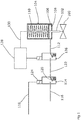
- this system includes a safety critical valve 200 such as a ball valve, fitted with a fail-safe valve actuator 204, to be operated in one direction (the pressure stroke) by a fluid under pressure (such as compressed air) and in an opposite direction (the fail-safe direction) under the force exerted by a spring or other biasing means 210 (the spring stroke).
- the fluid under pressure is supplied under the control of a primary electro-pneumatic operator (such as a solenoid operated valve) 214, and a secondary electro-pneumatic operator 226 for delivering a partial stroke test when instructed, and a PST Controller 228 for running partial stroke testing.
- the system of figure 2 differs in that the actuator 204 has two independently controllable pressurised bores 208a and 208b. Each bore has an operating piston 206a, 206b, and the actuator 204 is arranged such that both pistons must be pressurised in order for the actuator to be fully stroked to the position required to hold the valve 200 in its normal operating position. Pressure is supplied to both operating pistons 206a, 206b via the Primary SOV 214, and thus a safety trigger that actuates the primary SOV 214 will release the pressure in both pistons and move the valve 200 into its safe state.
- the Secondary SOV 226 (under control of the PST controller 228) is fitted to only one of the pressurised chambers 208a of the actuator in such a way that only one of the operating pistons 206a in the actuator 204 can be affected by its operation when a partial stroke test (PST) is initiated.
- the other piston 206b will remain under whatever pressure is supplied by the primary SOV 214 under control of the safety system, notwithstanding operation of the secondary SOV 226 under the control of the PST Controller 228.
- an instruction from the PST Controller 228 causes the Secondary SOV 226 to change state such that the pressurised chamber 208a that it is connected to (and only this chamber) is de-pressurised. This allows the spring 210 in the actuator 204 to start moving the actuator 204 and valve 200 connected to it in the direction of the safe position for the system.
- the PST Controller 228 will allow the actuator 204 and valve 200 to move to a pre-defined position (the 'PST Position') before changing the state of the Secondary SOV 226, re-pressurising the chamber 208a that it is connected to, along with the associated operating piston 206a, and returning the system to the position required during normal operation.
- the spring 210 whilst the spring 210 is moving the actuator 204 and valve 200 to the PST position, it will also be driving the other operating piston 206b in the actuator 204 in the direction of the safe position for the system.
- the operating media in the pressure chamber 208b containing this piston 206b will be further compressed as the spring 210 drives the actuator 204 and valve 200 to the PST Position, further increasing the pressure in the chamber 208b.
- FIG. 2 One arrangement for the actuator 204 including two pressurised chambers is shown in figure 2 .
- the two chambers 208a, 208b are aligned co-axially, and a single pushrod 202 extends from the piston 206a in chamber 208a, into and through chamber 208b where it is also connected to piston 206b, and then out of the actuator 204 to connect to the valve 200.
- Other arrangements are of course possible.
Landscapes
- Engineering & Computer Science (AREA)
- General Engineering & Computer Science (AREA)
- Mechanical Engineering (AREA)
- Physics & Mathematics (AREA)
- General Physics & Mathematics (AREA)
- Automation & Control Theory (AREA)
- Fluid Mechanics (AREA)
- Fluid-Pressure Circuits (AREA)
Claims (16)
- Système de soupape de sécurité, comprenant :une soupape pouvant être actionnée pour bouger entre un état de fonctionnement et un état sûr,un actionneur de soupape relié de manière opérationnelle à la soupape pour commander son état, et comprenant :une sollicitation vers l'état sûr,une paire d'éléments d'entraînement mus par un milieu de pression, chacun agissant contre la sollicitation pour pousser la soupape vers l'état de fonctionnement,une première soupape de commande agencée de façon à transporter sélectivement un milieu de pression aux deux éléments d'entraînement et à retirer l'alimentation lors de la réception d'un déclenchement de sécurité, etune deuxième soupape de commande agencée de façon à transporter sélectivement un milieu de pression à seulement un élément d'entraînement de la paire et à retirer l'alimentation lors de la réception d'un signal d'essai.
- Système de soupape de sécurité selon la revendication 1, dans lequel les éléments d'entraînement sont des pistons fonctionnant à l'intérieur d'alésages et le milieu de pression est alimenté à ces alésages sur un côté des pistons.
- Système de soupape de sécurité selon la revendication 2, dans lequel les alésages sont coaxiaux.
- Système de soupape de sécurité selon la revendication 3, dans lequel les deux pistons agissent sur une seule tringlerie d'entraînement qui agit sur la soupape.
- Système de soupape de sécurité selon la revendication 4, dans lequel la liaison d'entraînement est une tige poussoir.
- Système de soupape de sécurité selon la revendication 4, dans lequel la liaison d'entraînement est un arbre rotatif.
- Système de soupape de sécurité selon l'une quelconque des revendications précédentes, dans lequel la paire d'éléments d'entraînement agissent de manière combinée contre la sollicitation pour pousser la soupape vers l'état de fonctionnement.
- Système de soupape de sécurité selon l'une quelconque des revendications précédentes, dans lequel la deuxième soupape de commande est disposée en série entre la première soupape de commande et l'élément d'entraînement unique.
- Système de soupape de sécurité selon l'une quelconque des revendications précédentes, dans lequel la première soupape de commande transporte un milieu de pression via deux conduits, un menant à chaque élément d'entraînement et la deuxième soupape de commande est disposée sur un de ces conduits pour transporter sélectivement le milieu de pression jusqu'à l'élément d'entraînement unique.
- Système de soupape de sécurité selon l'une quelconque des revendications précédentes, dans lequel le milieu de pression est un gaz.
- Système de soupape de sécurité selon l'une quelconque des revendications précédentes, dans lequel le milieu de pression est de l'air.
- Système de soupape de sécurité selon l'une quelconque des revendications précédentes, dans lequel le milieu de pression est pressurisé jusqu'à une pression élevée.
- Système de soupape de sécurité selon l'une quelconque des revendications précédentes, dans lequel la première et/ou la deuxième soupape de commande sont des soupapes électro-pneumatiques ou électro-hydrauliques.
- Système de soupape de sécurité selon l'une quelconque des revendications précédentes, dans lequel une unité de commande fournit un signal d'essai à la deuxième soupape de commande.
- Système de soupape de sécurité selon la revendication 14, dans lequel l'unité de commande reçoit un signal de position de soupape de la soupape.
- Système de soupape de sécurité selon la revendication 14 ou la revendication 15, dans lequel l'unité de commande est adaptée de façon à fournir un signal d'essai à la deuxième soupape de commande jusqu'à ce que le signal de position de soupape ait changé de plus qu'un seuil prédéterminé.
Applications Claiming Priority (1)
| Application Number | Priority Date | Filing Date | Title |
|---|---|---|---|
| GB1604645.0A GB2548562A (en) | 2016-03-18 | 2016-03-18 | Testing of safety devices |
Publications (2)
| Publication Number | Publication Date |
|---|---|
| EP3220221A1 EP3220221A1 (fr) | 2017-09-20 |
| EP3220221B1 true EP3220221B1 (fr) | 2019-07-10 |
Family
ID=55968547
Family Applications (1)
| Application Number | Title | Priority Date | Filing Date |
|---|---|---|---|
| EP17160669.2A Active EP3220221B1 (fr) | 2016-03-18 | 2017-03-13 | Essai de dispositifs de sécurité |
Country Status (3)
| Country | Link |
|---|---|
| US (1) | US10302221B2 (fr) |
| EP (1) | EP3220221B1 (fr) |
| GB (1) | GB2548562A (fr) |
Cited By (1)
| Publication number | Priority date | Publication date | Assignee | Title |
|---|---|---|---|---|
| RU2821195C1 (ru) * | 2019-10-24 | 2024-06-18 | Линде Гмбх | Способ эксплуатации технологической установки и технологическая установка |
Families Citing this family (7)
| Publication number | Priority date | Publication date | Assignee | Title |
|---|---|---|---|---|
| EP3067763B1 (fr) * | 2015-03-11 | 2022-06-29 | Siemens Aktiengesellschaft | Attribution de capteurs à des pièces de machine |
| IT201800007206A1 (it) * | 2018-07-16 | 2020-01-16 | Sistema di controllo e di sicurezza per circuiti di convogliamento di fluidi in pressione | |
| US11255350B2 (en) * | 2019-08-21 | 2022-02-22 | Hybrid Automation Inc. | Method and apparatus for conversion of single-acting pneumatic actuator to electric power platform |
| US11732733B2 (en) * | 2019-08-21 | 2023-08-22 | Hybrid Automation Inc. | Method and apparatus for conversion of a pneumatic actuator to an electric power platform |
| EP4049099B1 (fr) * | 2019-10-24 | 2024-09-04 | Linde GmbH | Procédé de fonctionnement d'un système d'ingénierie de processus et système d'ingénierie de processus |
| DE102019135327B3 (de) * | 2019-12-19 | 2021-01-07 | Samson Aktiengesellschaft | Verfahren zum Prüfen der Funktionsfähigkeit eines Magnetventils zum Auslösen eines Sicherheitsventils |
| JP7407771B2 (ja) * | 2021-06-21 | 2024-01-04 | 日本電子株式会社 | 電子ビーム検査装置 |
Family Cites Families (13)
| Publication number | Priority date | Publication date | Assignee | Title |
|---|---|---|---|---|
| GB2201227B (en) * | 1987-02-18 | 1991-05-22 | Ferranti Plc | Hydraulic valve |
| FI116587B (fi) * | 1997-10-17 | 2005-12-30 | Metso Automation Oy | Menetelmä ja laitteisto turvalaitteen toimintakunnon todentamiseksi |
| US6003605A (en) * | 1997-12-01 | 1999-12-21 | Halliburton Enery Services, Inc. | Balanced line tubing retrievable safety valve |
| US6435022B1 (en) * | 2001-02-09 | 2002-08-20 | Tareq Nasser Albuaijan | Partial stroke testing system |
| US7621293B2 (en) * | 2001-04-05 | 2009-11-24 | Fisher Controls International Llc | Versatile emergency shutdown device controller implementing a pneumatic test for a system instrument device |
| US6935610B1 (en) * | 2003-01-17 | 2005-08-30 | Dynatorque, Inc. | Partial stroke valve test apparatus |
| GB2404239A (en) * | 2003-07-25 | 2005-01-26 | Ics Triplex Technology Ltd | Partial stroke valve test apparatus to test emergency shutdown valves |
| DE102006003750B4 (de) * | 2005-01-28 | 2014-02-27 | Samson Ag | Verfahren zum Nachweis einer Durchführung einer Überprüfung einer Funktionsfähigkeit eines Sicherheitsventils |
| DE102005004477B4 (de) * | 2005-01-31 | 2013-02-07 | Samson Ag | Verfahren zur Überprüfung einer Funktionsfähigkeit eines Stellgliedes, insbesondere für ein Sicherheitsventil |
| US8074512B2 (en) * | 2008-02-28 | 2011-12-13 | Tareq Nasser Al-Buaijan | Partial stroke testing system coupled with fuel control valve |
| WO2013120837A1 (fr) * | 2012-02-14 | 2013-08-22 | Shell Internationale Research Maatschappij B.V. | Procédé de production d'hydrocarbure gazeux d'un puits de forage et ensemble vanne |
| JP6006635B2 (ja) * | 2012-12-26 | 2016-10-12 | アズビル株式会社 | 安全計装システムおよびpst起動方法 |
| US9752599B2 (en) * | 2014-05-07 | 2017-09-05 | Fisher Controls International Llc | Methods and apparatus to partial stroke test valves using pressure control |
-
2016
- 2016-03-18 GB GB1604645.0A patent/GB2548562A/en not_active Withdrawn
-
2017
- 2017-02-23 US US15/440,941 patent/US10302221B2/en active Active
- 2017-03-13 EP EP17160669.2A patent/EP3220221B1/fr active Active
Non-Patent Citations (1)
| Title |
|---|
| None * |
Cited By (1)
| Publication number | Priority date | Publication date | Assignee | Title |
|---|---|---|---|---|
| RU2821195C1 (ru) * | 2019-10-24 | 2024-06-18 | Линде Гмбх | Способ эксплуатации технологической установки и технологическая установка |
Also Published As
| Publication number | Publication date |
|---|---|
| GB2548562A (en) | 2017-09-27 |
| US10302221B2 (en) | 2019-05-28 |
| US20170268695A1 (en) | 2017-09-21 |
| EP3220221A1 (fr) | 2017-09-20 |
| GB201604645D0 (en) | 2016-05-04 |
Similar Documents
| Publication | Publication Date | Title |
|---|---|---|
| US10302221B2 (en) | Testing of safety devices | |
| CN108374696B (zh) | 蒸汽涡轮阀驱动装置 | |
| US9880564B2 (en) | Position controller for a pneumatic field device | |
| CN102292582B (zh) | 具有失控设备的致动器 | |
| US20140026747A1 (en) | Hydraulic or pneumatic drive for actuating a fitting comprising a control valve or selector valve | |
| RU2558487C2 (ru) | Устройство для увеличения усиления привода с блокирующим устройством | |
| WO2021002907A3 (fr) | Ensemble de servo-vanne de flexion de bague piézoélectrique pour actionnement de commande de vol d'aéronef et systèmes de commande de carburant | |
| JP5718381B2 (ja) | 自閉式停止弁に用いられる流れ制御アクチュエータ装置 | |
| US11235861B2 (en) | Horizontal stabilizer trim actuator systems and methods | |
| EP3824192B1 (fr) | Système de commande et de sécurité pour circuits de transport de fluides sous pression | |
| EP3247886B1 (fr) | Agencement de course partielle de soupape de déclenchement pneumatique | |
| JP5053027B2 (ja) | 緊急遮断弁装置 | |
| JPH0478515B2 (fr) | ||
| CN112238935B (zh) | 致动器控制布置 | |
| JP5289810B2 (ja) | 緊急遮断弁装置 | |
| JP5053028B2 (ja) | 緊急遮断弁装置 | |
| US20220266982A1 (en) | Blade pitch control | |
| US12117099B2 (en) | Method for testing the functionality of a solenoid valve for triggering a safety valve | |
| US12145265B2 (en) | Pivot joint | |
| US8419345B2 (en) | Actuator | |
| JP7353243B2 (ja) | 空気作動弁の駆動機構 | |
| US12454959B2 (en) | Actuating device, having two valves which are connected in parallel, for the sensitive and full range regulation of any volumetric flow | |
| EP3333376A1 (fr) | Circuit de commande électrique pour un moteur à turbine | |
| WO2019048850A1 (fr) | Test de course partielle pour actionneur de soupape pneumatique | |
| EP4445031A1 (fr) | Actionneur à fluide |
Legal Events
| Date | Code | Title | Description |
|---|---|---|---|
| PUAI | Public reference made under article 153(3) epc to a published international application that has entered the european phase |
Free format text: ORIGINAL CODE: 0009012 |
|
| STAA | Information on the status of an ep patent application or granted ep patent |
Free format text: STATUS: THE APPLICATION HAS BEEN PUBLISHED |
|
| AK | Designated contracting states |
Kind code of ref document: A1 Designated state(s): AL AT BE BG CH CY CZ DE DK EE ES FI FR GB GR HR HU IE IS IT LI LT LU LV MC MK MT NL NO PL PT RO RS SE SI SK SM TR |
|
| AX | Request for extension of the european patent |
Extension state: BA ME |
|
| STAA | Information on the status of an ep patent application or granted ep patent |
Free format text: STATUS: REQUEST FOR EXAMINATION WAS MADE |
|
| 17P | Request for examination filed |
Effective date: 20180223 |
|
| RBV | Designated contracting states (corrected) |
Designated state(s): AL AT BE BG CH CY CZ DE DK EE ES FI FR GB GR HR HU IE IS IT LI LT LU LV MC MK MT NL NO PL PT RO RS SE SI SK SM TR |
|
| GRAP | Despatch of communication of intention to grant a patent |
Free format text: ORIGINAL CODE: EPIDOSNIGR1 |
|
| STAA | Information on the status of an ep patent application or granted ep patent |
Free format text: STATUS: GRANT OF PATENT IS INTENDED |
|
| RIC1 | Information provided on ipc code assigned before grant |
Ipc: F16K 37/00 20060101ALI20190110BHEP Ipc: G05B 9/02 20060101ALI20190110BHEP Ipc: G05B 19/46 20060101ALI20190110BHEP Ipc: G05B 23/02 20060101ALI20190110BHEP Ipc: G05B 19/042 20060101AFI20190110BHEP Ipc: F15B 19/00 20060101ALI20190110BHEP |
|
| INTG | Intention to grant announced |
Effective date: 20190130 |
|
| GRAS | Grant fee paid |
Free format text: ORIGINAL CODE: EPIDOSNIGR3 |
|
| GRAA | (expected) grant |
Free format text: ORIGINAL CODE: 0009210 |
|
| STAA | Information on the status of an ep patent application or granted ep patent |
Free format text: STATUS: THE PATENT HAS BEEN GRANTED |
|
| AK | Designated contracting states |
Kind code of ref document: B1 Designated state(s): AL AT BE BG CH CY CZ DE DK EE ES FI FR GB GR HR HU IE IS IT LI LT LU LV MC MK MT NL NO PL PT RO RS SE SI SK SM TR |
|
| REG | Reference to a national code |
Ref country code: GB Ref legal event code: FG4D |
|
| REG | Reference to a national code |
Ref country code: CH Ref legal event code: EP Ref country code: AT Ref legal event code: REF Ref document number: 1154226 Country of ref document: AT Kind code of ref document: T Effective date: 20190715 |
|
| REG | Reference to a national code |
Ref country code: IE Ref legal event code: FG4D |
|
| REG | Reference to a national code |
Ref country code: DE Ref legal event code: R096 Ref document number: 602017005096 Country of ref document: DE |
|
| REG | Reference to a national code |
Ref country code: NL Ref legal event code: FP |
|
| RAP2 | Party data changed (patent owner data changed or rights of a patent transferred) |
Owner name: IMTEX CONTROLS LIMITED |
|
| REG | Reference to a national code |
Ref country code: LT Ref legal event code: MG4D |
|
| REG | Reference to a national code |
Ref country code: AT Ref legal event code: MK05 Ref document number: 1154226 Country of ref document: AT Kind code of ref document: T Effective date: 20190710 |
|
| PG25 | Lapsed in a contracting state [announced via postgrant information from national office to epo] |
Ref country code: AT Free format text: LAPSE BECAUSE OF FAILURE TO SUBMIT A TRANSLATION OF THE DESCRIPTION OR TO PAY THE FEE WITHIN THE PRESCRIBED TIME-LIMIT Effective date: 20190710 Ref country code: SE Free format text: LAPSE BECAUSE OF FAILURE TO SUBMIT A TRANSLATION OF THE DESCRIPTION OR TO PAY THE FEE WITHIN THE PRESCRIBED TIME-LIMIT Effective date: 20190710 Ref country code: NO Free format text: LAPSE BECAUSE OF FAILURE TO SUBMIT A TRANSLATION OF THE DESCRIPTION OR TO PAY THE FEE WITHIN THE PRESCRIBED TIME-LIMIT Effective date: 20191010 Ref country code: FI Free format text: LAPSE BECAUSE OF FAILURE TO SUBMIT A TRANSLATION OF THE DESCRIPTION OR TO PAY THE FEE WITHIN THE PRESCRIBED TIME-LIMIT Effective date: 20190710 Ref country code: BG Free format text: LAPSE BECAUSE OF FAILURE TO SUBMIT A TRANSLATION OF THE DESCRIPTION OR TO PAY THE FEE WITHIN THE PRESCRIBED TIME-LIMIT Effective date: 20191010 Ref country code: PT Free format text: LAPSE BECAUSE OF FAILURE TO SUBMIT A TRANSLATION OF THE DESCRIPTION OR TO PAY THE FEE WITHIN THE PRESCRIBED TIME-LIMIT Effective date: 20191111 Ref country code: HR Free format text: LAPSE BECAUSE OF FAILURE TO SUBMIT A TRANSLATION OF THE DESCRIPTION OR TO PAY THE FEE WITHIN THE PRESCRIBED TIME-LIMIT Effective date: 20190710 Ref country code: LT Free format text: LAPSE BECAUSE OF FAILURE TO SUBMIT A TRANSLATION OF THE DESCRIPTION OR TO PAY THE FEE WITHIN THE PRESCRIBED TIME-LIMIT Effective date: 20190710 |
|
| PG25 | Lapsed in a contracting state [announced via postgrant information from national office to epo] |
Ref country code: ES Free format text: LAPSE BECAUSE OF FAILURE TO SUBMIT A TRANSLATION OF THE DESCRIPTION OR TO PAY THE FEE WITHIN THE PRESCRIBED TIME-LIMIT Effective date: 20190710 Ref country code: LV Free format text: LAPSE BECAUSE OF FAILURE TO SUBMIT A TRANSLATION OF THE DESCRIPTION OR TO PAY THE FEE WITHIN THE PRESCRIBED TIME-LIMIT Effective date: 20190710 Ref country code: GR Free format text: LAPSE BECAUSE OF FAILURE TO SUBMIT A TRANSLATION OF THE DESCRIPTION OR TO PAY THE FEE WITHIN THE PRESCRIBED TIME-LIMIT Effective date: 20191011 Ref country code: AL Free format text: LAPSE BECAUSE OF FAILURE TO SUBMIT A TRANSLATION OF THE DESCRIPTION OR TO PAY THE FEE WITHIN THE PRESCRIBED TIME-LIMIT Effective date: 20190710 Ref country code: IS Free format text: LAPSE BECAUSE OF FAILURE TO SUBMIT A TRANSLATION OF THE DESCRIPTION OR TO PAY THE FEE WITHIN THE PRESCRIBED TIME-LIMIT Effective date: 20191110 Ref country code: RS Free format text: LAPSE BECAUSE OF FAILURE TO SUBMIT A TRANSLATION OF THE DESCRIPTION OR TO PAY THE FEE WITHIN THE PRESCRIBED TIME-LIMIT Effective date: 20190710 |
|
| PG25 | Lapsed in a contracting state [announced via postgrant information from national office to epo] |
Ref country code: TR Free format text: LAPSE BECAUSE OF FAILURE TO SUBMIT A TRANSLATION OF THE DESCRIPTION OR TO PAY THE FEE WITHIN THE PRESCRIBED TIME-LIMIT Effective date: 20190710 |
|
| PG25 | Lapsed in a contracting state [announced via postgrant information from national office to epo] |
Ref country code: DK Free format text: LAPSE BECAUSE OF FAILURE TO SUBMIT A TRANSLATION OF THE DESCRIPTION OR TO PAY THE FEE WITHIN THE PRESCRIBED TIME-LIMIT Effective date: 20190710 Ref country code: PL Free format text: LAPSE BECAUSE OF FAILURE TO SUBMIT A TRANSLATION OF THE DESCRIPTION OR TO PAY THE FEE WITHIN THE PRESCRIBED TIME-LIMIT Effective date: 20190710 Ref country code: RO Free format text: LAPSE BECAUSE OF FAILURE TO SUBMIT A TRANSLATION OF THE DESCRIPTION OR TO PAY THE FEE WITHIN THE PRESCRIBED TIME-LIMIT Effective date: 20190710 Ref country code: EE Free format text: LAPSE BECAUSE OF FAILURE TO SUBMIT A TRANSLATION OF THE DESCRIPTION OR TO PAY THE FEE WITHIN THE PRESCRIBED TIME-LIMIT Effective date: 20190710 |
|
| PG25 | Lapsed in a contracting state [announced via postgrant information from national office to epo] |
Ref country code: CZ Free format text: LAPSE BECAUSE OF FAILURE TO SUBMIT A TRANSLATION OF THE DESCRIPTION OR TO PAY THE FEE WITHIN THE PRESCRIBED TIME-LIMIT Effective date: 20190710 Ref country code: SM Free format text: LAPSE BECAUSE OF FAILURE TO SUBMIT A TRANSLATION OF THE DESCRIPTION OR TO PAY THE FEE WITHIN THE PRESCRIBED TIME-LIMIT Effective date: 20190710 Ref country code: IS Free format text: LAPSE BECAUSE OF FAILURE TO SUBMIT A TRANSLATION OF THE DESCRIPTION OR TO PAY THE FEE WITHIN THE PRESCRIBED TIME-LIMIT Effective date: 20200224 Ref country code: SK Free format text: LAPSE BECAUSE OF FAILURE TO SUBMIT A TRANSLATION OF THE DESCRIPTION OR TO PAY THE FEE WITHIN THE PRESCRIBED TIME-LIMIT Effective date: 20190710 |
|
| REG | Reference to a national code |
Ref country code: DE Ref legal event code: R097 Ref document number: 602017005096 Country of ref document: DE |
|
| PLBE | No opposition filed within time limit |
Free format text: ORIGINAL CODE: 0009261 |
|
| STAA | Information on the status of an ep patent application or granted ep patent |
Free format text: STATUS: NO OPPOSITION FILED WITHIN TIME LIMIT |
|
| PG2D | Information on lapse in contracting state deleted |
Ref country code: IS |
|
| 26N | No opposition filed |
Effective date: 20200603 |
|
| PG25 | Lapsed in a contracting state [announced via postgrant information from national office to epo] |
Ref country code: SI Free format text: LAPSE BECAUSE OF FAILURE TO SUBMIT A TRANSLATION OF THE DESCRIPTION OR TO PAY THE FEE WITHIN THE PRESCRIBED TIME-LIMIT Effective date: 20190710 |
|
| REG | Reference to a national code |
Ref country code: DE Ref legal event code: R119 Ref document number: 602017005096 Country of ref document: DE |
|
| PG25 | Lapsed in a contracting state [announced via postgrant information from national office to epo] |
Ref country code: MC Free format text: LAPSE BECAUSE OF FAILURE TO SUBMIT A TRANSLATION OF THE DESCRIPTION OR TO PAY THE FEE WITHIN THE PRESCRIBED TIME-LIMIT Effective date: 20190710 |
|
| REG | Reference to a national code |
Ref country code: CH Ref legal event code: PL |
|
| REG | Reference to a national code |
Ref country code: BE Ref legal event code: MM Effective date: 20200331 |
|
| PG25 | Lapsed in a contracting state [announced via postgrant information from national office to epo] |
Ref country code: LU Free format text: LAPSE BECAUSE OF NON-PAYMENT OF DUE FEES Effective date: 20200313 |
|
| PG25 | Lapsed in a contracting state [announced via postgrant information from national office to epo] |
Ref country code: IE Free format text: LAPSE BECAUSE OF NON-PAYMENT OF DUE FEES Effective date: 20200313 Ref country code: DE Free format text: LAPSE BECAUSE OF NON-PAYMENT OF DUE FEES Effective date: 20201001 Ref country code: CH Free format text: LAPSE BECAUSE OF NON-PAYMENT OF DUE FEES Effective date: 20200331 Ref country code: LI Free format text: LAPSE BECAUSE OF NON-PAYMENT OF DUE FEES Effective date: 20200331 Ref country code: FR Free format text: LAPSE BECAUSE OF NON-PAYMENT OF DUE FEES Effective date: 20200331 |
|
| PG25 | Lapsed in a contracting state [announced via postgrant information from national office to epo] |
Ref country code: BE Free format text: LAPSE BECAUSE OF NON-PAYMENT OF DUE FEES Effective date: 20200331 |
|
| PG25 | Lapsed in a contracting state [announced via postgrant information from national office to epo] |
Ref country code: MT Free format text: LAPSE BECAUSE OF FAILURE TO SUBMIT A TRANSLATION OF THE DESCRIPTION OR TO PAY THE FEE WITHIN THE PRESCRIBED TIME-LIMIT Effective date: 20190710 Ref country code: CY Free format text: LAPSE BECAUSE OF FAILURE TO SUBMIT A TRANSLATION OF THE DESCRIPTION OR TO PAY THE FEE WITHIN THE PRESCRIBED TIME-LIMIT Effective date: 20190710 |
|
| PG25 | Lapsed in a contracting state [announced via postgrant information from national office to epo] |
Ref country code: MK Free format text: LAPSE BECAUSE OF FAILURE TO SUBMIT A TRANSLATION OF THE DESCRIPTION OR TO PAY THE FEE WITHIN THE PRESCRIBED TIME-LIMIT Effective date: 20190710 |
|
| PGFP | Annual fee paid to national office [announced via postgrant information from national office to epo] |
Ref country code: GB Payment date: 20260305 Year of fee payment: 10 |
|
| PGFP | Annual fee paid to national office [announced via postgrant information from national office to epo] |
Ref country code: IT Payment date: 20260311 Year of fee payment: 10 |
|
| PGFP | Annual fee paid to national office [announced via postgrant information from national office to epo] |
Ref country code: NL Payment date: 20260306 Year of fee payment: 10 |