EP3220247A2 - Dispositif de détermination et procédé de détermination - Google Patents
Dispositif de détermination et procédé de détermination Download PDFInfo
- Publication number
- EP3220247A2 EP3220247A2 EP17157292.8A EP17157292A EP3220247A2 EP 3220247 A2 EP3220247 A2 EP 3220247A2 EP 17157292 A EP17157292 A EP 17157292A EP 3220247 A2 EP3220247 A2 EP 3220247A2
- Authority
- EP
- European Patent Office
- Prior art keywords
- operating object
- threshold value
- variations
- capacitances
- value
- Prior art date
- Legal status (The legal status is an assumption and is not a legal conclusion. Google has not performed a legal analysis and makes no representation as to the accuracy of the status listed.)
- Granted
Links
Images


Classifications
-
- G—PHYSICS
- G06—COMPUTING OR CALCULATING; COUNTING
- G06F—ELECTRIC DIGITAL DATA PROCESSING
- G06F3/00—Input arrangements for transferring data to be processed into a form capable of being handled by the computer; Output arrangements for transferring data from processing unit to output unit, e.g. interface arrangements
- G06F3/01—Input arrangements or combined input and output arrangements for interaction between user and computer
- G06F3/03—Arrangements for converting the position or the displacement of a member into a coded form
- G06F3/041—Digitisers, e.g. for touch screens or touch pads, characterised by the transducing means
- G06F3/044—Digitisers, e.g. for touch screens or touch pads, characterised by the transducing means by capacitive means
- G06F3/0446—Digitisers, e.g. for touch screens or touch pads, characterised by the transducing means by capacitive means using a grid-like structure of electrodes in at least two directions, e.g. using row and column electrodes
-
- G—PHYSICS
- G06—COMPUTING OR CALCULATING; COUNTING
- G06F—ELECTRIC DIGITAL DATA PROCESSING
- G06F3/00—Input arrangements for transferring data to be processed into a form capable of being handled by the computer; Output arrangements for transferring data from processing unit to output unit, e.g. interface arrangements
- G06F3/01—Input arrangements or combined input and output arrangements for interaction between user and computer
- G06F3/03—Arrangements for converting the position or the displacement of a member into a coded form
- G06F3/041—Digitisers, e.g. for touch screens or touch pads, characterised by the transducing means
- G06F3/0416—Control or interface arrangements specially adapted for digitisers
- G06F3/0418—Control or interface arrangements specially adapted for digitisers for error correction or compensation, e.g. based on parallax, calibration or alignment
- G06F3/04186—Touch location disambiguation
Definitions
- the present invention relates to a device and method for determining whether an operating object is in a touch state relative to an operation surface.
- WO 2012/169106 discloses a technique for determining a measurement value (e.g., the area of part of an operation surface where capacitances have changed) responsive to the presence or absence of a glove and the thickness of the glove, for example, at the time when a user unlocks a touch panel, and setting a sensitivity level of the touch panel based on the measurement value.
- a measurement value e.g., the area of part of an operation surface where capacitances have changed
- the related-art technique requires measurement of proper sensitivities of the touch panel in advance.
- the present invention provides a determination device and method that are capable of dealing with operations performed by, for example, fingers wearing gloves having different thicknesses without previously measuring sensitivities for the different thicknesses.
- An aspect of the present invention provides a determination device including a sensor unit for detecting capacitances that vary in response to a touch or proximity of an operating object on or to an operation surface, a setting unit for setting a first threshold value based on a temporal change in variations in the detected capacitances, and a determination unit for determining, based on a result of comparison between the variations in the detected capacitances and the set first threshold value, whether the operating object is in a touch state relative to the operation surface.
- the first threshold value used for touch state determination is set based on the temporal change in variations in the detected capacitances, this configuration enables dealing with operations performed by, for example, fingers wearing gloves having different thicknesses without previously measuring first threshold values (sensitivities) for the different thicknesses of gloves.
- the setting unit may set, based on a maximum value of the variations in the capacitances changing over time in response to movement of the operating object, the first threshold value less than the maximum value.
- the first threshold value less than the maximum value can be set based on the maximum value of the variations in the capacitances changing over time.
- the determination device may further include an identification unit for identifying the operating object based on the variations in the detected capacitances.
- the setting unit may set the first threshold value each time the identification unit identifies a new operating object.
- the first threshold value may be set each time an operating object is identified.
- the first threshold value can be appropriately set and used each time an operating object is identified.
- the identification unit may identify one or more operating objects individually, the setting unit may set the first threshold value for each of the identified operating objects, and the determination unit may determine, for each of the identified operating objects, whether the operating object is in the touch state.
- the first threshold value may be set for each of multiple operating objects.
- the first threshold value can be appropriately set and used for each operating object.
- the identification unit may specify, based on a distribution of the variations in the detected capacitances in the operation surface, a peak value of the variations in the capacitances related to the identified operating object.
- the setting unit may set the first threshold value based on a temporal change in the specified peak value.
- the determination unit may determine, based on a result of comparison between the specified peak value and the set first threshold value, whether the operating object is in the touch state.
- the peak value of the variations in the capacitances related to the operating object can be used to set the first threshold value and determine whether the operation object is in the touch state.
- the term "peak value” as used herein refers to a value specified based on a distribution of the variations in the detected capacitances in the operation surface.
- the peak value can refer to a spatial maximum value of variations in capacitances in the operation surface.
- the determination unit determines the operating object to be not in the touch state regardless of the result of comparison between the specified peak value and the first threshold value.
- the operating object when the peak value changes at a relatively low rate, namely, when the operating object approaches the operation surface at a relatively low speed, the operating object can be determined to be not in the touch state.
- a touch or proximity of the operating object moving at a relatively low speed on or to the operation surface can be an unintentional touch or proximity.
- a likelihood that an unintentional touch or proximity may be determined to be the touch state is reduced or eliminated.
- the determination unit determines the operating object to be not in the touch state regardless of the result of comparison between the specified peak value and the first threshold value.
- the operating object when a period of time between the time when an operating object is identified and the time when the operating object reaches a position corresponding to the second threshold value is relatively long, namely, when the operating object moves at a relatively low speed after the operating object is identified, the operating object can be determined to be not in the touch state.
- a touch or proximity of the operating object moving at a relatively low speed on or to the operation surface after the operating object is identified can be an unintentional touch or proximity.
- a likelihood that an unintentional touch or proximity may be determined to be the touch state is reduced or eliminated.
- the setting unit may set the first threshold value based on a temporal change in the specified peak value after the peak value is greater than or equal to the second threshold value.
- the first threshold value may be set after the peak value is greater than or equal to the second threshold value. If an operating object is determined to be not in the touch state based on a time taken for the operating object to reach a position corresponding to the second threshold value, setting the first threshold value can be omitted.
- the identification unit may specify, based on a distribution of the variations in the detected capacitances in the operation surface, an area of a region where the identified operating object touches or is close to the operation surface. When the area is greater than or equal to a predetermined value, the determination unit may determine the operating object to be not in the touch state regardless of the result of comparison between the variations in the detected capacitances and the first threshold value.
- the operating object can be determined to be not in the touch state.
- a touch or proximity of the operating object on or to a region having a relatively large area in the operation surface can be an unintentional touch or proximity.
- a likelihood that an unintentional touch or proximity may be determined to be the touch state is reduced or eliminated.
- Another aspect of the present invention provides a determination device including a setting unit for setting a first threshold value based on a temporal change in variations in capacitances that vary in response to a touch or proximity of an operating object on or to an operation surface and a determination unit for determining, based on a result of comparison between the variations in the capacitances and the set first threshold value, whether the operating object is in a touch state relative to the operation surface.
- the first threshold value used for touch state determination is set based on the temporal change in variations in the capacitances, this configuration enables dealing with operations performed by, for example, fingers wearing gloves having different thicknesses without previously measuring first threshold values (sensitivities) for the different thicknesses of gloves.
- Another aspect of the present invention provides a determination method including detecting capacitances that vary in response to a touch or proximity of an operating object on or to an operation surface, setting a first threshold value based on a temporal change in variations in the detected capacitances, and determining, based on a result of comparison between the variations in the detected capacitances and the set first threshold value, whether the operating object is in a touch state relative to the operation surface.
- the first threshold value used for touch state determination is set based on the temporal change in the variations in the detected capacitances, this configuration enables dealing with operations performed by, for example, fingers wearing gloves having different thicknesses without previously measuring first threshold values (sensitivities) for the different thicknesses of gloves.
- Fig. 1 is a diagram of an exemplary configuration of a determination device 1 according to an embodiment.
- the determination device 1 includes a sensor unit 10, a processor 20, a storage unit 30, and an interface unit 40.
- the determination device 1 determines whether an operating object, such as a finger, is in a touch state relative to an operation surface.
- the determination device 1 constitutes at least part of an input apparatus, such as a touch pad or a touch panel, capable of inputting information in response to a touch operation on the operation surface.
- the sensor unit 10 detects capacitances that vary in response to a touch or proximity (hereinafter, also simply referred to as "proximity") of an object in a plurality of detection positions arranged on the operation surface, and generates detection data indicating a detection result.
- the sensor unit 10 includes a sensor matrix 11, a detection data generation section 13, and a driving section 14.
- the sensor matrix 11 includes a matrix of capacitive sensor elements (capacitors) 12 each having a capacitance that varies with the degree of proximity of an object to the capacitive sensor element 12.
- the detection data generation section 13 generates detection data based on the capacitances of the capacitive sensor elements 12.
- the driving section 14 applies a driving voltage to the capacitive sensor elements 12.
- the sensor matrix 11 includes a plurality of driving electrodes Lx extending in a longitudinal direction of the sensor matrix 11 and a plurality of detecting electrodes Ly extending in a lateral direction of the sensor matrix 11.
- the driving electrodes Lx are arranged parallel to one another in the lateral direction and the detecting electrodes Ly are arranged parallel to one another in the longitudinal direction.
- the driving electrodes Lx are insulated from the detecting electrodes Ly.
- the driving electrodes Lx intersect the detecting electrodes Ly, thus forming a lattice pattern.
- the capacitive sensor element 12 is disposed in the vicinity of each of the intersections of the driving electrodes Lx and the detecting electrodes Ly.
- the electrodes Lx and Ly are strip-shaped in Fig. 1 , the electrodes may have any other shape or pattern, such as a diamond pattern.
- the driving section 14 applies a driving voltage to each capacitive sensor element 12 of the sensor matrix 11. For example, the driving section 14 sequentially selects one of the driving electrodes Lx and periodically changes the potential of the selected driving electrode Lx under the control of the processor 20. A change in potential of the driving electrode Lx within a predetermined range causes a driving voltage applied to the capacitive sensor element 12 disposed in the vicinity of each intersection of the driving electrode Lx and the detecting electrode Ly to change within a predetermined range, thus charging or discharging the capacitive sensor element 12.
- the detection data generation section 13 generates detection data that depends on charge transferred in each detecting electrode Ly when the capacitive sensor element 12 is charged or discharged in response to a driving voltage applied by the driving section 14. Specifically, the detection data generation section 13 samples charge transferred in each detecting electrode Ly synchronously with a periodic change in driving voltage applied by the driving section 14, and generates detection data based on a sampling result.
- the detection data generation section 13 includes a capacitance-to-voltage conversion circuit (CV conversion circuit) that outputs a voltage responsive to a capacitance of the capacitive sensor element 12 and an analog-to-digital conversion circuit (AD conversion circuit) that converts an output signal of the CV conversion circuit to a digital signal and outputs the signal as detection data.
- CV conversion circuit capacitance-to-voltage conversion circuit
- AD conversion circuit analog-to-digital conversion circuit
- the CV conversion circuit samples charge transferred in the detecting electrode Ly under the control of the processor 20 each time the capacitive sensor element 12 is charged or discharged in response to a periodic change in driving voltage applied by the driving section 14. Specifically, each time a positive or negative charge is transferred in the detecting electrode Ly, the CV conversion circuit transfers this charge or a charge proportional thereto to a reference capacitor, and outputs a signal responsive to a voltage generated in the reference capacitor. For example, the CV conversion circuit outputs a signal responsive to an integrated value or an average value of charge periodically transferred in the detecting electrode Ly or charge proportional thereto. Under the control of the processor 20, the AD conversion circuit converts the output signal of the CV conversion circuit to a digital signal at predetermined intervals, and outputs the digital signal as detection data.
- the sensor unit 10 is configured to detect a touch or proximity of an object in response to a variation in capacitance (mutual capacitance) between the electrodes (Lx, Ly).
- the sensor unit 10 may have any other configuration.
- the sensor unit 10 may detect a proximity of an object using any of various methods.
- the sensor unit 10 may be of a type that detects a capacitance (self-capacitance) formed between an electrode and ground by a close object.
- a driving voltage is applied to a detecting electrode.
- the processor 20 is a circuit that controls an overall operation of the determination device 1.
- the processor 20 includes a computer that performs a process in accordance with instruction codes of a program stored in the storage unit 30, which will be described later, and a logic circuit that achieves a specific function. Processing of the processor 20 may be entirely implemented by the computer and the program. Part or the whole of processing of the processor 20 may be implemented by a dedicated logic circuit.
- the processor 20 includes a sensor control unit 21, a two-dimensional data generation unit 22, an identification unit 23, a setting unit 24, and a determination unit 25.
- the sensor control unit 21 controls the sensor unit 10 to perform a detection operation of periodically detecting a proximity of an object to the operation surface in the detection positions (the capacitive sensor elements 12 of the sensor matrix 11). Specifically, the sensor control unit 21 controls the driving section 14 and the detection data generation section 13 so that driving electrode selection and pulse voltage generation in the driving section 14 and detecting electrode selection and detection data generation in the detection data generation section 13 are periodically performed at appropriate timings.
- the two-dimensional data generation unit 22 generates two-dimensional data 31 in matrix form based on a detection result of the sensor unit 10 and stores the data 31 into the storage unit 30.
- the two-dimensional data 31 contains a plurality of data items based on the degree of proximity of an object to the operation surface in the detection positions.
- the two-dimensional data generation unit 22 stores the detection data, output from the sensor unit 10, in matrix form into a storage area (current value memory) of the storage unit 30.
- the two-dimensional data generation unit 22 calculates differences between the detection data in matrix form stored in the current value memory and base values in matrix form previously stored in another storage area (base value memory) of the storage unit 30, and stores a calculation result indicating the differences as two-dimensional data 31 into the storage unit 30.
- the base value memory stores reference values (base values) of detection data for a non-proximity state in which any object is not close to the operation surface.
- the two-dimensional data 31 indicates variations (variations in capacitances) of detection data from the non-proximity state.
- the identification unit 23 identifies one or more operating objects close to the operation surface individually based on the two-dimensional data 31 generated by the two-dimensional data generation unit 22, and generates coordinates/peak-value data 32 for each identified operating object.
- the coordinates/peak-value data 32 indicates the coordinates of a position of the identified operating object on the operation surface and a variation (peak value) in capacitance at the position.
- the identification unit 23 specifies, based on the two-dimensional data 31, one or more proximity regions, serving as regions on the operation surface, in each of which capacitances vary in response to a proximity of the corresponding operating object.
- the identification unit 23 specifies, as a peak value, a maximum variation of variations in capacitances (hereinafter, “capacitance variations”) at a plurality of detection positions in each of the specified proximity regions, and generates the coordinates/peak-value data 32 indicating the coordinates of a detection position corresponding to the specified peak value and the peak value.
- peak value can also refer to a spatial maximum value of capacitance variations in a proximity region.
- the identification unit 23 identifies the same operating object for multiple cycles of the periodic detection operation of the sensor unit 10. For example, the identification unit 23 assigns an identical identification code to a plurality of coordinates/peak-value data items 32 about a single operating object generated over multiple cycles of the detection operation.
- the term "identification code" can refer to information for tracking a single operating object over multiple cycles.
- the identification unit 23 can identify or recognize a single operating object based on comparisons of proximity regions in a plurality of two-dimensional data items 31 generated over multiple cycles of the detection operation.
- the setting unit 24 sets a first threshold value T1 based on the coordinates/peak-value data 32 generated by the identification unit 23.
- the first threshold value T1 is used to determine whether an operating object is in the touch state.
- the setting unit 24 sets the first threshold value T1 based on a temporal change in peak value contained in the coordinates/peak-value data 32. An operation of setting the first threshold value T1 will be described in detail later.
- the determination unit 25 compares a peak value contained in the coordinates/peak-value data 32 with the first threshold value T1 set by the setting unit 24 to determine, based on a result of the comparison, whether an operating object is in the touch state.
- the determination unit 25 When the operating object is determined to be in the touch state, the determination unit 25 generates touch state data 33 indicating the touch state at the coordinates of a position corresponding to the operating object and stores the generated data into the storage unit 30. An operation of determining whether an operating object is in the touch state will be described in detail later.
- the storage unit 30 stores constant data and variable data to be used for processing of the processor 20. If the processor 20 includes a computer, the storage unit 30 may store a program executed by the computer.
- the storage unit 30 includes a volatile memory, such as a dynamic random access memory (DRAM) or a static RAM (SRAM), a non-volatile memory, such as a flash memory, and a hard disk.
- DRAM dynamic random access memory
- SRAM static RAM
- non-volatile memory such as a flash memory
- hard disk a hard disk.
- the interface unit 40 is a circuit through which the determination device 1 transmits and receives data to and from another controller (e.g., an integrated circuit (IC) for controlling an electronic apparatus including the determination device 1).
- the processor 20 outputs information stored in the storage unit 30 to the controller (not illustrated) through the interface unit 40.
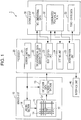
- FIG. 2 is a flowchart of an exemplary main process executed by the processor 20 of the determination device 1.
- the main process is executed every cycle of the detection operation of the sensor unit 10.
- the two-dimensional data generation unit 22 first generates two-dimensional data 31 (ST100). As described above, the two-dimensional data 31 is generated based on detection data obtained by the sensor unit 10.
- the identification unit 23 If there is an operating object close to the operation surface (Yes in ST110), the identification unit 23 generates coordinates/peak-value data 32 based on the two-dimensional data 31 (ST120). If there is no operating object close to the operation surface (No in ST110), the main process terminates. For example, if capacitance variations in multiple detection positions indicated by the two-dimensional data 31 are each zero or less than or equal to a reference value, it is determined that there is no operating object close to the operation surface.
- touch state determination (ST130) is performed as will be described with reference to Fig. 3 . If there are multiple operating objects close to the operation surface, the touch state determination is sequentially executed for each of the operating objects (Yes in ST140).
- Fig. 3 illustrates a flowchart of the touch state determination process. If the process is executed on a target operating object for the first time (Yes in ST200), the setting unit 24 sets a current peak value as a maximum value Pmax of a peak value changing over time (ST210). Specifically, the setting unit 24 stores, as the maximum value Pmax, a peak value contained in the coordinates/peak-value data 32 generated in ST120 of the main process into the storage unit 30.
- the determination unit 25 determines the operating object to be in a non-touch state (ST220).
- the touch state determination process terminates. As described above, in the first touch state determination process for an identified operating object close to the operation surface, the maximum peak value Pmax is set and the operating object is determined to be in the non-touch state.
- the determination unit 25 determines whether a non-touch state attribute is set for the operating object (ST230). In the second touch state determination process, the non-touch state attribute is not set (No in ST230). The setting unit 24 determines whether the first threshold value T1 is set (ST240). In the second touch state determination process, the first threshold value T1 is not set (No in ST240). The setting unit 24 determines whether the peak value is greater than or equal to a second threshold value T2 (ST250).
- the operating object While the peak value is less than the second threshold value T2 (No in ST250), the operating object is determined to be in the non-touch state (ST220).
- the second threshold value T2 functions as a lower limit of peak values at which the operating object can be determined to be in the touch state.
- the determination unit 25 determines whether an elapsed time t is greater than or equal to a reference value tr (ST260).
- elapsed time t refers to a time taken for the peak value to be greater than or equal to the second threshold value T2 after the operating object is identified (for example, after execution of the first touch state determination process).
- the determination unit 25 sets a non-touch state attribute for the operating object (ST270) and then determines the operating object to be in the non-touch state (ST220).
- the touch state determination process terminates.
- the operating object with the non-touch state attribute set (Yes in ST230) is immediately determined to be in the non-touch state (ST220).
- a touch by an operating object in the case where the elapsed time t (taken for the peak value to be greater than or equal to the second threshold value T2) is greater than or equal to the reference value tr is always determined to be the non-touch state.
- the setting unit 24 determines whether the peak value is greater than the maximum value Pmax (ST280). If the peak value is greater than the maximum value Pmax (Yes in ST280), namely, if the peak value is increasing as the operating object approaches the operation surface, the setting unit 24 sets the current peak value as the maximum value Pmax (ST290) and the determination unit 25 determines the operating object to be in the non-touch state (ST220). The touch state determination process terminates.
- the setting unit 24 sets the first threshold value T1 (ST300).
- the first threshold value T1 is set based on the peak value.
- the first threshold value T1 is set to be less than the peak value.
- a value obtained by multiplying the peak value by 0.8 is set as the first threshold value T1.
- the set first threshold value T1 is stored into the storage unit 30.
- the determination unit 25 determines whether the area, indicated at A, of a proximity region, serving as a region on the operation surface to which the operating object is close, is less than a reference value Ar (ST320). If the area A is less than the reference value Ar (Yes in ST320), the determination unit 25 determines the operating object to be in the touch state (ST330). The touch state determination process then terminates. As described above, in response to a determination that the operating object is in the touch state, the determination unit 25 generates touch state data 33 indicating the touch state at the coordinates of a position contained in the coordinates/peak-value data 32 and stores the data into the storage unit 30. On the other hand, if the area A is greater than or equal to the reference value Ar (No in ST320), the determination unit 25 determines the operating object to be in the non-touch state (ST220). The touch state determination process then terminates.
- the determination unit 25 determines whether the peak value is greater than or equal to the first threshold value T1. If the peak value is greater than or equal to the first threshold value T1 (Yes in ST310), the determination unit 25 determines, based on the value of the above-described area A, whether the operating object is in the touch state (ST320, ST330, and ST220). If the peak value is less than the first threshold value T1 (No in ST310), the determination unit 25 determines the operating object to be in the non-touch state. As described above, while the operating object is identified, whether the operating object is in the touch state is determined based on the same first threshold value T1.
- Fig. 4 is a diagram explaining that the first threshold value T1 is set in response to movement of an operating object and whether the operating object is in the touch state is determined.
- Upper part of Fig. 4 illustrates a change in proximity of an operating object F wearing a glove G to the operation surface (the sensor matrix 11).
- the horizontal axis of Fig. 4 denotes time.
- Lower part of Fig. 4 illustrates variations in capacitances caused in response to a proximity of the operating object F illustrated in the upper part of Fig. 4 .
- each bell-shaped curve corresponds to capacitance variations in a proximity region to which the operating object F is close at certain time.
- the top of the curve corresponds to a peak value at this time.
- the peak value increases (P1 to P2).
- the peak value stops increasing (P2).
- the first threshold value T1 that is less than the peak value (P2) is set and the operating object F is determined to be in the touch state.
- whether the operating object F is in the touch state is determined based on a result of comparison between the first threshold value T1 and the peak value.
- the peak value (P6) is greater than or equal to the first threshold value T1
- the operating object F is determined to be in the touch state.
- the peak value (P3 to P5, P7, and P8) is less than the first threshold value T1, the operating object F is determined to be in the non-touch state.
- Fig. 5 is a diagram comparatively explaining touch state determinations related to operating objects wearing gloves having different thicknesses.
- Fig. 5 illustrates changes in proximity of the operating objects and variations in capacitances caused in response to proximities of the operating objects in a manner similar to Fig. 4 .
- Left part of Fig. 5 corresponds to a case of the operating object F wearing a glove G1
- right part of Fig. 5 corresponds to a case of the operating object F wearing a glove G2 that is thinner than the glove G1.
- Fig. 6 is a diagram comparatively explaining changes in variations in capacitances caused by operating objects approaching the operation surface at different speeds.
- Fig. 6 illustrates changes in proximity of the operating objects and variations in capacitances caused in response to proximities of the operating objects in a manner similar to Figs. 4 and 5 .
- Left part of Fig. 6 illustrates a case where the operating object F moves to the operation surface at a relatively low speed
- right part of Fig. 6 illustrates a case where the operating object F moves to the operation surface at a relatively high speed.
- a time t1 taken for the peak value to be greater than or equal to the second threshold value T2 after the operating object F is identified is long.
- a time t2 taken for the peak value to be greater than or equal to the second threshold value T2 after the operating object F is identified is short.
- a touch by an operating object in the case where the elapsed time t taken for the peak value to be greater than or equal to the second threshold value T2 is greater than or equal to the reference value tr is always determined to be the non-touch state.
- the operating object F approaches the operation surface at a relatively low speed as illustrated in the left part of Fig. 6
- a touch by the operating object F is always determined to be the non-touch state.
- a proximity of the operating object F approaching the operation surface at a relatively low speed may be an unintentional proximity to the operation surface.
- a likelihood that an unintentional proximity may be determined to be the touch state is reduced or eliminated.
- Figs. 7 and 8 each illustrate an exemplary proximity region as a region on the operation surface to which an operating object is close.
- Fig. 7 illustrates a proximity region A1 in a whole area WA of the operation surface.
- the proximity region A1 includes a portion A11 where capacitance variations are relatively small and a portion A12 where capacitance variations are relatively large.
- Fig. 8 illustrates a proximity region A2 whose area is greater than that of the above-described proximity region A1 in the whole area WA of the operation surface.
- the proximity region A2 includes a portion A21 where capacitance variations are relatively small and portions A22 where capacitance variations are relatively large.
- the proximity region A2 in Fig. 8 has an area greater than that of the proximity region A1 in Fig. 7 .
- a proximity in a proximity region whose area A is greater than or equal to the reference value Ar is determined to be the non-touch state.
- a proximity in this proximity region is determined to be the non-touch state.
- a proximity of an operating object in a proximity region having a large area in the operation surface may be an unintentional proximity.
- a likelihood that an unintentional proximity may be determined to be the touch state is reduced or eliminated.
- the first threshold value T1 for touch state determination is set based on a temporal change in variations in detected capacitances (peak value at the time when the peak value stops increasing).
- the determination device 1 can deal with operations by, for example, fingers wearing gloves having different thicknesses without previously measuring first threshold values T1 (sensitivities) for the different thicknesses of the gloves.
- a non-touch state determination based on the elapsed time t taken for a peak value to be greater than or equal to the second threshold value T2 may be optional.
- the second threshold value T2 serving as a lower limit of peak values at which an operating object can be determined to be in the touch state, may be optional.
- a non-touch state determination based on the area A of a proximity region may be optional.
- the present invention can be employed in, for example, a touch panel and a touch pad.
Landscapes
- Engineering & Computer Science (AREA)
- General Engineering & Computer Science (AREA)
- Theoretical Computer Science (AREA)
- Human Computer Interaction (AREA)
- Physics & Mathematics (AREA)
- General Physics & Mathematics (AREA)
- Position Input By Displaying (AREA)
- Geophysics And Detection Of Objects (AREA)
- Electronic Switches (AREA)
Applications Claiming Priority (1)
| Application Number | Priority Date | Filing Date | Title |
|---|---|---|---|
| JP2016037173A JP6704754B2 (ja) | 2016-02-29 | 2016-02-29 | 判定装置及び判定方法 |
Publications (3)
| Publication Number | Publication Date |
|---|---|
| EP3220247A2 true EP3220247A2 (fr) | 2017-09-20 |
| EP3220247A3 EP3220247A3 (fr) | 2017-12-13 |
| EP3220247B1 EP3220247B1 (fr) | 2022-05-11 |
Family
ID=58108504
Family Applications (1)
| Application Number | Title | Priority Date | Filing Date |
|---|---|---|---|
| EP17157292.8A Active EP3220247B1 (fr) | 2016-02-29 | 2017-02-22 | Dispositif de détermination de contact et procédé de détermination |
Country Status (2)
| Country | Link |
|---|---|
| EP (1) | EP3220247B1 (fr) |
| JP (1) | JP6704754B2 (fr) |
Cited By (2)
| Publication number | Priority date | Publication date | Assignee | Title |
|---|---|---|---|---|
| CN116366048A (zh) * | 2022-12-22 | 2023-06-30 | 明见(厦门)技术有限公司 | 一种方向盘上人手位置检测方法及系统 |
| EP4398149A1 (fr) * | 2023-01-09 | 2024-07-10 | Thales Dis France Sas | Carte à puce pour transactions sans contact |
Families Citing this family (1)
| Publication number | Priority date | Publication date | Assignee | Title |
|---|---|---|---|---|
| JP7658829B2 (ja) * | 2021-07-26 | 2025-04-08 | 株式会社東海理化電機製作所 | 操作検出装置 |
Citations (1)
| Publication number | Priority date | Publication date | Assignee | Title |
|---|---|---|---|---|
| WO2012169106A1 (fr) | 2011-06-10 | 2012-12-13 | Necカシオモバイルコミュニケーションズ株式会社 | Dispositif d'entrée et procédé de commande d'un panneau tactile |
Family Cites Families (11)
| Publication number | Priority date | Publication date | Assignee | Title |
|---|---|---|---|---|
| JP2010257046A (ja) * | 2009-04-22 | 2010-11-11 | Mitsubishi Electric Corp | 近接検知装置 |
| CN102782623B (zh) * | 2010-03-01 | 2015-12-02 | 松下知识产权经营株式会社 | 显示装置 |
| WO2013021858A1 (fr) * | 2011-08-05 | 2013-02-14 | Necカシオモバイルコミュニケーションズ株式会社 | Unité d'entrée d'informations, procédé d'entrée d'informations et programme d'ordinateur |
| TW201322070A (zh) * | 2011-11-21 | 2013-06-01 | Novatek Microelectronics Corp | 雜訊過濾方法 |
| AU2014201384A1 (en) * | 2013-03-13 | 2014-10-02 | Samsung Electronics Co., Ltd. | Method and apparatus for operating touch screen |
| JP2014209291A (ja) * | 2013-04-16 | 2014-11-06 | シャープ株式会社 | タッチセンサ装置および携帯端末 |
| JP2015032235A (ja) * | 2013-08-06 | 2015-02-16 | ソニー株式会社 | タッチ検出回路、タッチ検出方法、および電子機器 |
| US9213458B2 (en) * | 2013-10-14 | 2015-12-15 | Parade Technologies, Ltd. | Hover position calculation in a touchscreen device |
| JP5962634B2 (ja) * | 2013-11-28 | 2016-08-03 | 株式会社デンソー | 電子機器 |
| JP2015130122A (ja) * | 2014-01-08 | 2015-07-16 | 株式会社デンソー | 静電容量式操作装置 |
| JP6571030B2 (ja) * | 2016-03-15 | 2019-09-04 | アルプスアルパイン株式会社 | 入力装置とその制御方法及びプログラム |
-
2016
- 2016-02-29 JP JP2016037173A patent/JP6704754B2/ja active Active
-
2017
- 2017-02-22 EP EP17157292.8A patent/EP3220247B1/fr active Active
Patent Citations (1)
| Publication number | Priority date | Publication date | Assignee | Title |
|---|---|---|---|---|
| WO2012169106A1 (fr) | 2011-06-10 | 2012-12-13 | Necカシオモバイルコミュニケーションズ株式会社 | Dispositif d'entrée et procédé de commande d'un panneau tactile |
Cited By (3)
| Publication number | Priority date | Publication date | Assignee | Title |
|---|---|---|---|---|
| CN116366048A (zh) * | 2022-12-22 | 2023-06-30 | 明见(厦门)技术有限公司 | 一种方向盘上人手位置检测方法及系统 |
| EP4398149A1 (fr) * | 2023-01-09 | 2024-07-10 | Thales Dis France Sas | Carte à puce pour transactions sans contact |
| WO2024149753A1 (fr) * | 2023-01-09 | 2024-07-18 | Thales Dis France Sas | Carte à puce pour transactions sans contact |
Also Published As
| Publication number | Publication date |
|---|---|
| JP6704754B2 (ja) | 2020-06-03 |
| JP2017156823A (ja) | 2017-09-07 |
| EP3220247B1 (fr) | 2022-05-11 |
| EP3220247A3 (fr) | 2017-12-13 |
Similar Documents
| Publication | Publication Date | Title |
|---|---|---|
| TWI659342B (zh) | Touch sensor type electronic device and sensor control method | |
| US8797280B2 (en) | Systems and methods for improved touch screen response | |
| EP3032389B1 (fr) | Dispositif d'entrée et procédé et programme de commande de celui-ci | |
| EP3220247B1 (fr) | Dispositif de détermination de contact et procédé de détermination | |
| EP3141990B1 (fr) | Appareil d'entrée, procédé de commande de celui-ci et programme | |
| JP6278889B2 (ja) | 入力装置とその制御方法及びプログラム | |
| CN105892746A (zh) | 一种触控方法以及电子设备 | |
| EP3136207B1 (fr) | Appareil d'entrée, procédé de commande et programme | |
| EP3220243B1 (fr) | Dispositif d'entrée, procédé de commande d'un dispositif d'entrée et programme | |
| JP6219264B2 (ja) | 入力装置とその制御方法及びプログラム | |
| US10073564B2 (en) | Input device, control method of input device, and program | |
| US10175815B2 (en) | Electrostatic input device | |
| JP6278888B2 (ja) | 入力装置とその制御方法及びプログラム | |
| US10788941B2 (en) | Method for detecting contact on a capacitive sensor element | |
| JP2017156919A (ja) | 入力装置とその制御方法及びプログラム | |
| KR102104275B1 (ko) | 스타일러스 펜을 이용하는 터치 시스템 및 이를 이용한 터치 검출 방법 | |
| JP6262576B2 (ja) | 静電入力装置 | |
| JP6219260B2 (ja) | 入力装置とその制御方法及びプログラム |
Legal Events
| Date | Code | Title | Description |
|---|---|---|---|
| PUAI | Public reference made under article 153(3) epc to a published international application that has entered the european phase |
Free format text: ORIGINAL CODE: 0009012 |
|
| STAA | Information on the status of an ep patent application or granted ep patent |
Free format text: STATUS: THE APPLICATION HAS BEEN PUBLISHED |
|
| AK | Designated contracting states |
Kind code of ref document: A2 Designated state(s): AL AT BE BG CH CY CZ DE DK EE ES FI FR GB GR HR HU IE IS IT LI LT LU LV MC MK MT NL NO PL PT RO RS SE SI SK SM TR |
|
| AX | Request for extension of the european patent |
Extension state: BA ME |
|
| PUAL | Search report despatched |
Free format text: ORIGINAL CODE: 0009013 |
|
| RIC1 | Information provided on ipc code assigned before grant |
Ipc: G06F 3/044 20060101AFI20171031BHEP |
|
| AK | Designated contracting states |
Kind code of ref document: A3 Designated state(s): AL AT BE BG CH CY CZ DE DK EE ES FI FR GB GR HR HU IE IS IT LI LT LU LV MC MK MT NL NO PL PT RO RS SE SI SK SM TR |
|
| AX | Request for extension of the european patent |
Extension state: BA ME |
|
| RIC1 | Information provided on ipc code assigned before grant |
Ipc: G06F 3/044 20060101AFI20171108BHEP |
|
| STAA | Information on the status of an ep patent application or granted ep patent |
Free format text: STATUS: REQUEST FOR EXAMINATION WAS MADE |
|
| 17P | Request for examination filed |
Effective date: 20180605 |
|
| RBV | Designated contracting states (corrected) |
Designated state(s): AL AT BE BG CH CY CZ DE DK EE ES FI FR GB GR HR HU IE IS IT LI LT LU LV MC MK MT NL NO PL PT RO RS SE SI SK SM TR |
|
| RAP1 | Party data changed (applicant data changed or rights of an application transferred) |
Owner name: ALPS ALPINE CO., LTD. |
|
| STAA | Information on the status of an ep patent application or granted ep patent |
Free format text: STATUS: EXAMINATION IS IN PROGRESS |
|
| 17Q | First examination report despatched |
Effective date: 20191016 |
|
| GRAP | Despatch of communication of intention to grant a patent |
Free format text: ORIGINAL CODE: EPIDOSNIGR1 |
|
| STAA | Information on the status of an ep patent application or granted ep patent |
Free format text: STATUS: GRANT OF PATENT IS INTENDED |
|
| INTG | Intention to grant announced |
Effective date: 20211209 |
|
| GRAS | Grant fee paid |
Free format text: ORIGINAL CODE: EPIDOSNIGR3 |
|
| GRAA | (expected) grant |
Free format text: ORIGINAL CODE: 0009210 |
|
| STAA | Information on the status of an ep patent application or granted ep patent |
Free format text: STATUS: THE PATENT HAS BEEN GRANTED |
|
| AK | Designated contracting states |
Kind code of ref document: B1 Designated state(s): AL AT BE BG CH CY CZ DE DK EE ES FI FR GB GR HR HU IE IS IT LI LT LU LV MC MK MT NL NO PL PT RO RS SE SI SK SM TR |
|
| REG | Reference to a national code |
Ref country code: GB Ref legal event code: FG4D |
|
| REG | Reference to a national code |
Ref country code: CH Ref legal event code: EP |
|
| REG | Reference to a national code |
Ref country code: AT Ref legal event code: REF Ref document number: 1492006 Country of ref document: AT Kind code of ref document: T Effective date: 20220515 |
|
| REG | Reference to a national code |
Ref country code: DE Ref legal event code: R096 Ref document number: 602017057222 Country of ref document: DE |
|
| REG | Reference to a national code |
Ref country code: IE Ref legal event code: FG4D |
|
| REG | Reference to a national code |
Ref country code: LT Ref legal event code: MG9D |
|
| REG | Reference to a national code |
Ref country code: NL Ref legal event code: MP Effective date: 20220511 |
|
| REG | Reference to a national code |
Ref country code: AT Ref legal event code: MK05 Ref document number: 1492006 Country of ref document: AT Kind code of ref document: T Effective date: 20220511 |
|
| PG25 | Lapsed in a contracting state [announced via postgrant information from national office to epo] |
Ref country code: SE Free format text: LAPSE BECAUSE OF FAILURE TO SUBMIT A TRANSLATION OF THE DESCRIPTION OR TO PAY THE FEE WITHIN THE PRESCRIBED TIME-LIMIT Effective date: 20220511 Ref country code: PT Free format text: LAPSE BECAUSE OF FAILURE TO SUBMIT A TRANSLATION OF THE DESCRIPTION OR TO PAY THE FEE WITHIN THE PRESCRIBED TIME-LIMIT Effective date: 20220912 Ref country code: NO Free format text: LAPSE BECAUSE OF FAILURE TO SUBMIT A TRANSLATION OF THE DESCRIPTION OR TO PAY THE FEE WITHIN THE PRESCRIBED TIME-LIMIT Effective date: 20220811 Ref country code: NL Free format text: LAPSE BECAUSE OF FAILURE TO SUBMIT A TRANSLATION OF THE DESCRIPTION OR TO PAY THE FEE WITHIN THE PRESCRIBED TIME-LIMIT Effective date: 20220511 Ref country code: LT Free format text: LAPSE BECAUSE OF FAILURE TO SUBMIT A TRANSLATION OF THE DESCRIPTION OR TO PAY THE FEE WITHIN THE PRESCRIBED TIME-LIMIT Effective date: 20220511 Ref country code: HR Free format text: LAPSE BECAUSE OF FAILURE TO SUBMIT A TRANSLATION OF THE DESCRIPTION OR TO PAY THE FEE WITHIN THE PRESCRIBED TIME-LIMIT Effective date: 20220511 Ref country code: GR Free format text: LAPSE BECAUSE OF FAILURE TO SUBMIT A TRANSLATION OF THE DESCRIPTION OR TO PAY THE FEE WITHIN THE PRESCRIBED TIME-LIMIT Effective date: 20220812 Ref country code: FI Free format text: LAPSE BECAUSE OF FAILURE TO SUBMIT A TRANSLATION OF THE DESCRIPTION OR TO PAY THE FEE WITHIN THE PRESCRIBED TIME-LIMIT Effective date: 20220511 Ref country code: ES Free format text: LAPSE BECAUSE OF FAILURE TO SUBMIT A TRANSLATION OF THE DESCRIPTION OR TO PAY THE FEE WITHIN THE PRESCRIBED TIME-LIMIT Effective date: 20220511 Ref country code: BG Free format text: LAPSE BECAUSE OF FAILURE TO SUBMIT A TRANSLATION OF THE DESCRIPTION OR TO PAY THE FEE WITHIN THE PRESCRIBED TIME-LIMIT Effective date: 20220811 Ref country code: AT Free format text: LAPSE BECAUSE OF FAILURE TO SUBMIT A TRANSLATION OF THE DESCRIPTION OR TO PAY THE FEE WITHIN THE PRESCRIBED TIME-LIMIT Effective date: 20220511 |
|
| PG25 | Lapsed in a contracting state [announced via postgrant information from national office to epo] |
Ref country code: RS Free format text: LAPSE BECAUSE OF FAILURE TO SUBMIT A TRANSLATION OF THE DESCRIPTION OR TO PAY THE FEE WITHIN THE PRESCRIBED TIME-LIMIT Effective date: 20220511 Ref country code: PL Free format text: LAPSE BECAUSE OF FAILURE TO SUBMIT A TRANSLATION OF THE DESCRIPTION OR TO PAY THE FEE WITHIN THE PRESCRIBED TIME-LIMIT Effective date: 20220511 Ref country code: LV Free format text: LAPSE BECAUSE OF FAILURE TO SUBMIT A TRANSLATION OF THE DESCRIPTION OR TO PAY THE FEE WITHIN THE PRESCRIBED TIME-LIMIT Effective date: 20220511 Ref country code: IS Free format text: LAPSE BECAUSE OF FAILURE TO SUBMIT A TRANSLATION OF THE DESCRIPTION OR TO PAY THE FEE WITHIN THE PRESCRIBED TIME-LIMIT Effective date: 20220911 |
|
| PG25 | Lapsed in a contracting state [announced via postgrant information from national office to epo] |
Ref country code: SM Free format text: LAPSE BECAUSE OF FAILURE TO SUBMIT A TRANSLATION OF THE DESCRIPTION OR TO PAY THE FEE WITHIN THE PRESCRIBED TIME-LIMIT Effective date: 20220511 Ref country code: SK Free format text: LAPSE BECAUSE OF FAILURE TO SUBMIT A TRANSLATION OF THE DESCRIPTION OR TO PAY THE FEE WITHIN THE PRESCRIBED TIME-LIMIT Effective date: 20220511 Ref country code: RO Free format text: LAPSE BECAUSE OF FAILURE TO SUBMIT A TRANSLATION OF THE DESCRIPTION OR TO PAY THE FEE WITHIN THE PRESCRIBED TIME-LIMIT Effective date: 20220511 Ref country code: EE Free format text: LAPSE BECAUSE OF FAILURE TO SUBMIT A TRANSLATION OF THE DESCRIPTION OR TO PAY THE FEE WITHIN THE PRESCRIBED TIME-LIMIT Effective date: 20220511 Ref country code: DK Free format text: LAPSE BECAUSE OF FAILURE TO SUBMIT A TRANSLATION OF THE DESCRIPTION OR TO PAY THE FEE WITHIN THE PRESCRIBED TIME-LIMIT Effective date: 20220511 Ref country code: CZ Free format text: LAPSE BECAUSE OF FAILURE TO SUBMIT A TRANSLATION OF THE DESCRIPTION OR TO PAY THE FEE WITHIN THE PRESCRIBED TIME-LIMIT Effective date: 20220511 |
|
| REG | Reference to a national code |
Ref country code: DE Ref legal event code: R097 Ref document number: 602017057222 Country of ref document: DE |
|
| PLBE | No opposition filed within time limit |
Free format text: ORIGINAL CODE: 0009261 |
|
| STAA | Information on the status of an ep patent application or granted ep patent |
Free format text: STATUS: NO OPPOSITION FILED WITHIN TIME LIMIT |
|
| PG25 | Lapsed in a contracting state [announced via postgrant information from national office to epo] |
Ref country code: AL Free format text: LAPSE BECAUSE OF FAILURE TO SUBMIT A TRANSLATION OF THE DESCRIPTION OR TO PAY THE FEE WITHIN THE PRESCRIBED TIME-LIMIT Effective date: 20220511 |
|
| 26N | No opposition filed |
Effective date: 20230214 |
|
| PG25 | Lapsed in a contracting state [announced via postgrant information from national office to epo] |
Ref country code: SI Free format text: LAPSE BECAUSE OF FAILURE TO SUBMIT A TRANSLATION OF THE DESCRIPTION OR TO PAY THE FEE WITHIN THE PRESCRIBED TIME-LIMIT Effective date: 20220511 |
|
| PG25 | Lapsed in a contracting state [announced via postgrant information from national office to epo] |
Ref country code: MC Free format text: LAPSE BECAUSE OF FAILURE TO SUBMIT A TRANSLATION OF THE DESCRIPTION OR TO PAY THE FEE WITHIN THE PRESCRIBED TIME-LIMIT Effective date: 20220511 |
|
| REG | Reference to a national code |
Ref country code: CH Ref legal event code: PL |
|
| REG | Reference to a national code |
Ref country code: BE Ref legal event code: MM Effective date: 20230228 |
|
| GBPC | Gb: european patent ceased through non-payment of renewal fee |
Effective date: 20230222 |
|
| PG25 | Lapsed in a contracting state [announced via postgrant information from national office to epo] |
Ref country code: LU Free format text: LAPSE BECAUSE OF NON-PAYMENT OF DUE FEES Effective date: 20230222 Ref country code: LI Free format text: LAPSE BECAUSE OF NON-PAYMENT OF DUE FEES Effective date: 20230228 Ref country code: CH Free format text: LAPSE BECAUSE OF NON-PAYMENT OF DUE FEES Effective date: 20230228 |
|
| REG | Reference to a national code |
Ref country code: IE Ref legal event code: MM4A |
|
| PG25 | Lapsed in a contracting state [announced via postgrant information from national office to epo] |
Ref country code: GB Free format text: LAPSE BECAUSE OF NON-PAYMENT OF DUE FEES Effective date: 20230222 |
|
| PG25 | Lapsed in a contracting state [announced via postgrant information from national office to epo] |
Ref country code: IT Free format text: LAPSE BECAUSE OF FAILURE TO SUBMIT A TRANSLATION OF THE DESCRIPTION OR TO PAY THE FEE WITHIN THE PRESCRIBED TIME-LIMIT Effective date: 20220511 Ref country code: IE Free format text: LAPSE BECAUSE OF NON-PAYMENT OF DUE FEES Effective date: 20230222 Ref country code: GB Free format text: LAPSE BECAUSE OF NON-PAYMENT OF DUE FEES Effective date: 20230222 Ref country code: FR Free format text: LAPSE BECAUSE OF NON-PAYMENT OF DUE FEES Effective date: 20230228 |
|
| PG25 | Lapsed in a contracting state [announced via postgrant information from national office to epo] |
Ref country code: BE Free format text: LAPSE BECAUSE OF NON-PAYMENT OF DUE FEES Effective date: 20230228 |
|
| PG25 | Lapsed in a contracting state [announced via postgrant information from national office to epo] |
Ref country code: BG Free format text: LAPSE BECAUSE OF FAILURE TO SUBMIT A TRANSLATION OF THE DESCRIPTION OR TO PAY THE FEE WITHIN THE PRESCRIBED TIME-LIMIT Effective date: 20220511 |
|
| PG25 | Lapsed in a contracting state [announced via postgrant information from national office to epo] |
Ref country code: BG Free format text: LAPSE BECAUSE OF FAILURE TO SUBMIT A TRANSLATION OF THE DESCRIPTION OR TO PAY THE FEE WITHIN THE PRESCRIBED TIME-LIMIT Effective date: 20220511 |
|
| PG25 | Lapsed in a contracting state [announced via postgrant information from national office to epo] |
Ref country code: CY Free format text: LAPSE BECAUSE OF FAILURE TO SUBMIT A TRANSLATION OF THE DESCRIPTION OR TO PAY THE FEE WITHIN THE PRESCRIBED TIME-LIMIT; INVALID AB INITIO Effective date: 20170222 |
|
| PG25 | Lapsed in a contracting state [announced via postgrant information from national office to epo] |
Ref country code: HU Free format text: LAPSE BECAUSE OF FAILURE TO SUBMIT A TRANSLATION OF THE DESCRIPTION OR TO PAY THE FEE WITHIN THE PRESCRIBED TIME-LIMIT; INVALID AB INITIO Effective date: 20170222 |
|
| PG25 | Lapsed in a contracting state [announced via postgrant information from national office to epo] |
Ref country code: TR Free format text: LAPSE BECAUSE OF FAILURE TO SUBMIT A TRANSLATION OF THE DESCRIPTION OR TO PAY THE FEE WITHIN THE PRESCRIBED TIME-LIMIT Effective date: 20220511 |
|
| PGFP | Annual fee paid to national office [announced via postgrant information from national office to epo] |
Ref country code: DE Payment date: 20260218 Year of fee payment: 10 |