EP3220261B1 - Mehrfachanzeigevorrichtung und verfahren zum betrieb davon - Google Patents
Mehrfachanzeigevorrichtung und verfahren zum betrieb davon Download PDFInfo
- Publication number
- EP3220261B1 EP3220261B1 EP17160152.9A EP17160152A EP3220261B1 EP 3220261 B1 EP3220261 B1 EP 3220261B1 EP 17160152 A EP17160152 A EP 17160152A EP 3220261 B1 EP3220261 B1 EP 3220261B1
- Authority
- EP
- European Patent Office
- Prior art keywords
- display
- image
- application
- display area
- electronic device
- Prior art date
- Legal status (The legal status is an assumption and is not a legal conclusion. Google has not performed a legal analysis and makes no representation as to the accuracy of the status listed.)
- Active
Links
Images












Classifications
-
- G—PHYSICS
- G06—COMPUTING OR CALCULATING; COUNTING
- G06F—ELECTRIC DIGITAL DATA PROCESSING
- G06F9/00—Arrangements for program control, e.g. control units
- G06F9/06—Arrangements for program control, e.g. control units using stored programs, i.e. using an internal store of processing equipment to receive or retain programs
- G06F9/44—Arrangements for executing specific programs
- G06F9/451—Execution arrangements for user interfaces
- G06F9/452—Remote windowing, e.g. X-Window System, desktop virtualisation
-
- G—PHYSICS
- G06—COMPUTING OR CALCULATING; COUNTING
- G06F—ELECTRIC DIGITAL DATA PROCESSING
- G06F3/00—Input arrangements for transferring data to be processed into a form capable of being handled by the computer; Output arrangements for transferring data from processing unit to output unit, e.g. interface arrangements
- G06F3/14—Digital output to display device ; Cooperation and interconnection of the display device with other functional units
- G06F3/147—Digital output to display device ; Cooperation and interconnection of the display device with other functional units using display panels
-
- G—PHYSICS
- G06—COMPUTING OR CALCULATING; COUNTING
- G06F—ELECTRIC DIGITAL DATA PROCESSING
- G06F1/00—Details not covered by groups G06F3/00 - G06F13/00 and G06F21/00
- G06F1/16—Constructional details or arrangements
- G06F1/1613—Constructional details or arrangements for portable computers
- G06F1/1626—Constructional details or arrangements for portable computers with a single-body enclosure integrating a flat display, e.g. Personal Digital Assistants [PDAs]
-
- G—PHYSICS
- G06—COMPUTING OR CALCULATING; COUNTING
- G06F—ELECTRIC DIGITAL DATA PROCESSING
- G06F1/00—Details not covered by groups G06F3/00 - G06F13/00 and G06F21/00
- G06F1/16—Constructional details or arrangements
- G06F1/1613—Constructional details or arrangements for portable computers
- G06F1/1633—Constructional details or arrangements of portable computers not specific to the type of enclosures covered by groups G06F1/1615 - G06F1/1626
- G06F1/1637—Details related to the display arrangement, including those related to the mounting of the display in the housing
- G06F1/1647—Details related to the display arrangement, including those related to the mounting of the display in the housing including at least an additional display
-
- G—PHYSICS
- G06—COMPUTING OR CALCULATING; COUNTING
- G06F—ELECTRIC DIGITAL DATA PROCESSING
- G06F3/00—Input arrangements for transferring data to be processed into a form capable of being handled by the computer; Output arrangements for transferring data from processing unit to output unit, e.g. interface arrangements
- G06F3/01—Input arrangements or combined input and output arrangements for interaction between user and computer
- G06F3/048—Interaction techniques based on graphical user interfaces [GUI]
- G06F3/0481—Interaction techniques based on graphical user interfaces [GUI] based on specific properties of the displayed interaction object or a metaphor-based environment, e.g. interaction with desktop elements like windows or icons, or assisted by a cursor's changing behaviour or appearance
-
- G—PHYSICS
- G06—COMPUTING OR CALCULATING; COUNTING
- G06F—ELECTRIC DIGITAL DATA PROCESSING
- G06F3/00—Input arrangements for transferring data to be processed into a form capable of being handled by the computer; Output arrangements for transferring data from processing unit to output unit, e.g. interface arrangements
- G06F3/01—Input arrangements or combined input and output arrangements for interaction between user and computer
- G06F3/048—Interaction techniques based on graphical user interfaces [GUI]
- G06F3/0481—Interaction techniques based on graphical user interfaces [GUI] based on specific properties of the displayed interaction object or a metaphor-based environment, e.g. interaction with desktop elements like windows or icons, or assisted by a cursor's changing behaviour or appearance
- G06F3/04817—Interaction techniques based on graphical user interfaces [GUI] based on specific properties of the displayed interaction object or a metaphor-based environment, e.g. interaction with desktop elements like windows or icons, or assisted by a cursor's changing behaviour or appearance using icons
-
- G—PHYSICS
- G06—COMPUTING OR CALCULATING; COUNTING
- G06F—ELECTRIC DIGITAL DATA PROCESSING
- G06F3/00—Input arrangements for transferring data to be processed into a form capable of being handled by the computer; Output arrangements for transferring data from processing unit to output unit, e.g. interface arrangements
- G06F3/01—Input arrangements or combined input and output arrangements for interaction between user and computer
- G06F3/048—Interaction techniques based on graphical user interfaces [GUI]
- G06F3/0484—Interaction techniques based on graphical user interfaces [GUI] for the control of specific functions or operations, e.g. selecting or manipulating an object, an image or a displayed text element, setting a parameter value or selecting a range
-
- G—PHYSICS
- G06—COMPUTING OR CALCULATING; COUNTING
- G06F—ELECTRIC DIGITAL DATA PROCESSING
- G06F3/00—Input arrangements for transferring data to be processed into a form capable of being handled by the computer; Output arrangements for transferring data from processing unit to output unit, e.g. interface arrangements
- G06F3/01—Input arrangements or combined input and output arrangements for interaction between user and computer
- G06F3/048—Interaction techniques based on graphical user interfaces [GUI]
- G06F3/0484—Interaction techniques based on graphical user interfaces [GUI] for the control of specific functions or operations, e.g. selecting or manipulating an object, an image or a displayed text element, setting a parameter value or selecting a range
- G06F3/0486—Drag-and-drop
-
- G—PHYSICS
- G06—COMPUTING OR CALCULATING; COUNTING
- G06F—ELECTRIC DIGITAL DATA PROCESSING
- G06F3/00—Input arrangements for transferring data to be processed into a form capable of being handled by the computer; Output arrangements for transferring data from processing unit to output unit, e.g. interface arrangements
- G06F3/01—Input arrangements or combined input and output arrangements for interaction between user and computer
- G06F3/048—Interaction techniques based on graphical user interfaces [GUI]
- G06F3/0487—Interaction techniques based on graphical user interfaces [GUI] using specific features provided by the input device, e.g. functions controlled by the rotation of a mouse with dual sensing arrangements, or of the nature of the input device, e.g. tap gestures based on pressure sensed by a digitiser
- G06F3/0488—Interaction techniques based on graphical user interfaces [GUI] using specific features provided by the input device, e.g. functions controlled by the rotation of a mouse with dual sensing arrangements, or of the nature of the input device, e.g. tap gestures based on pressure sensed by a digitiser using a touch-screen or digitiser, e.g. input of commands through traced gestures
-
- G—PHYSICS
- G06—COMPUTING OR CALCULATING; COUNTING
- G06F—ELECTRIC DIGITAL DATA PROCESSING
- G06F3/00—Input arrangements for transferring data to be processed into a form capable of being handled by the computer; Output arrangements for transferring data from processing unit to output unit, e.g. interface arrangements
- G06F3/01—Input arrangements or combined input and output arrangements for interaction between user and computer
- G06F3/048—Interaction techniques based on graphical user interfaces [GUI]
- G06F3/0487—Interaction techniques based on graphical user interfaces [GUI] using specific features provided by the input device, e.g. functions controlled by the rotation of a mouse with dual sensing arrangements, or of the nature of the input device, e.g. tap gestures based on pressure sensed by a digitiser
- G06F3/0488—Interaction techniques based on graphical user interfaces [GUI] using specific features provided by the input device, e.g. functions controlled by the rotation of a mouse with dual sensing arrangements, or of the nature of the input device, e.g. tap gestures based on pressure sensed by a digitiser using a touch-screen or digitiser, e.g. input of commands through traced gestures
- G06F3/04883—Interaction techniques based on graphical user interfaces [GUI] using specific features provided by the input device, e.g. functions controlled by the rotation of a mouse with dual sensing arrangements, or of the nature of the input device, e.g. tap gestures based on pressure sensed by a digitiser using a touch-screen or digitiser, e.g. input of commands through traced gestures for inputting data by handwriting, e.g. gesture or text
-
- G—PHYSICS
- G06—COMPUTING OR CALCULATING; COUNTING
- G06F—ELECTRIC DIGITAL DATA PROCESSING
- G06F3/00—Input arrangements for transferring data to be processed into a form capable of being handled by the computer; Output arrangements for transferring data from processing unit to output unit, e.g. interface arrangements
- G06F3/14—Digital output to display device ; Cooperation and interconnection of the display device with other functional units
- G06F3/1423—Digital output to display device ; Cooperation and interconnection of the display device with other functional units controlling a plurality of local displays, e.g. CRT and flat panel display
-
- G—PHYSICS
- G06—COMPUTING OR CALCULATING; COUNTING
- G06F—ELECTRIC DIGITAL DATA PROCESSING
- G06F3/00—Input arrangements for transferring data to be processed into a form capable of being handled by the computer; Output arrangements for transferring data from processing unit to output unit, e.g. interface arrangements
- G06F3/14—Digital output to display device ; Cooperation and interconnection of the display device with other functional units
- G06F3/1423—Digital output to display device ; Cooperation and interconnection of the display device with other functional units controlling a plurality of local displays, e.g. CRT and flat panel display
- G06F3/1431—Digital output to display device ; Cooperation and interconnection of the display device with other functional units controlling a plurality of local displays, e.g. CRT and flat panel display using a single graphics controller
-
- G—PHYSICS
- G09—EDUCATION; CRYPTOGRAPHY; DISPLAY; ADVERTISING; SEALS
- G09G—ARRANGEMENTS OR CIRCUITS FOR CONTROL OF INDICATING DEVICES USING STATIC MEANS TO PRESENT VARIABLE INFORMATION
- G09G3/00—Control arrangements or circuits, of interest only in connection with visual indicators other than cathode-ray tubes
- G09G3/20—Control arrangements or circuits, of interest only in connection with visual indicators other than cathode-ray tubes for presentation of an assembly of a number of characters, e.g. a page, by composing the assembly by combination of individual elements arranged in a matrix no fixed position being assigned to or needed to be assigned to the individual characters or partial characters
-
- G—PHYSICS
- G09—EDUCATION; CRYPTOGRAPHY; DISPLAY; ADVERTISING; SEALS
- G09G—ARRANGEMENTS OR CIRCUITS FOR CONTROL OF INDICATING DEVICES USING STATIC MEANS TO PRESENT VARIABLE INFORMATION
- G09G5/00—Control arrangements or circuits for visual indicators common to cathode-ray tube indicators and other visual indicators
-
- H—ELECTRICITY
- H04—ELECTRIC COMMUNICATION TECHNIQUE
- H04M—TELEPHONIC COMMUNICATION
- H04M1/00—Substation equipment, e.g. for use by subscribers
-
- H—ELECTRICITY
- H05—ELECTRIC TECHNIQUES NOT OTHERWISE PROVIDED FOR
- H05K—PRINTED CIRCUITS; CASINGS OR CONSTRUCTIONAL DETAILS OF ELECTRIC APPARATUS; MANUFACTURE OF ASSEMBLAGES OF ELECTRICAL COMPONENTS
- H05K7/00—Constructional details common to different types of electric apparatus
-
- G—PHYSICS
- G06—COMPUTING OR CALCULATING; COUNTING
- G06F—ELECTRIC DIGITAL DATA PROCESSING
- G06F2203/00—Indexing scheme relating to G06F3/00 - G06F3/048
- G06F2203/048—Indexing scheme relating to G06F3/048
- G06F2203/04803—Split screen, i.e. subdividing the display area or the window area into separate subareas
-
- G—PHYSICS
- G09—EDUCATION; CRYPTOGRAPHY; DISPLAY; ADVERTISING; SEALS
- G09G—ARRANGEMENTS OR CIRCUITS FOR CONTROL OF INDICATING DEVICES USING STATIC MEANS TO PRESENT VARIABLE INFORMATION
- G09G2300/00—Aspects of the constitution of display devices
- G09G2300/02—Composition of display devices
- G09G2300/023—Display panel composed of stacked panels
-
- G—PHYSICS
- G09—EDUCATION; CRYPTOGRAPHY; DISPLAY; ADVERTISING; SEALS
- G09G—ARRANGEMENTS OR CIRCUITS FOR CONTROL OF INDICATING DEVICES USING STATIC MEANS TO PRESENT VARIABLE INFORMATION
- G09G2300/00—Aspects of the constitution of display devices
- G09G2300/04—Structural and physical details of display devices
- G09G2300/0421—Structural details of the set of electrodes
- G09G2300/0426—Layout of electrodes and connections
Definitions
- the present disclosure relates to a multiple display device with a number of display areas, and a method of operating the device.
- US 2005/0264471 A1 discloses a thin display device having a plurality of panels and an electronic apparatus using such a display device.
- US 2016/0048316 A1 discloses a method for providing a user interface, in which an electronic device divides a display region into a main region and a sub-region and displays default information or event information on the sub-region.
- US 2014/0062976 A1 discloses a terminal including a sensor to sense bending of a flexible display and a controller to control display of information on the display.
- EP 2626852 A2 discloses a display apparatus.
- US 2013/076591 A1 discloses a multi-display device adapted to turn on and off certain device functionality based on one or more of device state and triggers.
- US 2016/070423 A1 discloses systems, methods and GUIs for combined switching and placement of windows based on a single action.
- Various embodiments also provide a method of operating the multiple display device.
- an electronic device according to claim 1.
- the electronic device includes: a housing including a first side facing a first direction, a second side facing a second direction opposite the first direction, and sides each of which partially encloses both edges of the first and second sides; a display including a first image-display area on the first side, a second image-display area on the second side, and third image-display areas on the sides; a communication circuit configured to perform wireless communication with an external device; a processor that is located in the housing and is electrically connected to the display and the communication circuit; and a memory that is located in the housing, is electrically connected to the processor, and stores a first application with a first user interface, a second application with a second user interface, and instructions.
- the instructions enable the processor to: display the first user interface on the first image-display area; display text or icons related to the second application on the third image-display area; receive a first user input for selecting an object located in the first image-display area; receive, when the first user input is received, a second user input for selecting the text or the icon located in the third image-display area; and display the second user interface on the second image-display area, in response to the second user input, and execute corresponding to the text or the icon.
- the method includes: executing a first application, and displaying a first user interface on a first image-display area; displaying text or icons related to a second application on a third image-display area; receiving a first user input for selecting an object located in the first image-display area; receiving, when the first user input is received, a second user input for selecting the text or the icon located in the third image-display area; and executing the second application corresponding to the text or the icon, and displaying a second user interface on the second image-display area.
- FIGURES 1 through 31 discussed below, and the various embodiments used to describe the principles of the present disclosure in this patent document are by way of illustration only and should not be construed in any way to limit the scope of the disclosure. Those skilled in the art will understand that the principles of the present disclosure may be implemented in any suitably arranged electronic device.
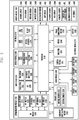
- FIG. 1 is a block diagram illustrating a configuration of an electronic device according to an embodiment of the present disclosure.
- the sensor module 240 may include, for example, an E-nose sensor (not illustrated), an electromyography (EMG) sensor (not illustrated), an electroencephalogram (EEG) sensor (not illustrated), an electrocardiogram (ECG) sensor (not illustrated), a fingerprint sensor (not illustrated), and the like. Additionally or alternatively, the sensor module 240 may include, for example, an E-nose sensor (not illustrated), an EMG sensor (not illustrated), an EEG sensor (not illustrated), an ECG sensor (not illustrated), a fingerprint sensor, and the like. The sensor module 240 may further include a control circuit (not illustrated) for controlling one or more sensors included therein.
- EMG electromyography
- EEG electroencephalogram
- ECG electrocardiogram
- a fingerprint sensor not illustrated
- the sensor module 240 may include, for example, an E-nose sensor (not illustrated), an EMG sensor (not illustrated), an EEG sensor (not illustrated), an ECG sensor (not illustrated), a fingerprint sensor, and the like.
- the sensor module 240 may further include a control
- the display module 260 may include a panel 262, a hologram 264, or projector 266.
- the display module 260 may be, for example, the display module 160 illustrated in FIG. 1 .
- the panel 262 may be, for example, a liquid crystal display (LCD) and an active matrix organic light emitting diode (AM-OLED) display, and the like.
- the panel 262 may be implemented so as to be, for example, flexible, transparent, or wearable.
- the panel 262 may include the touch panel 252 and one module.
- the hologram 264 may display a three-dimensional image in the air by using interference of light.
- the display module 260 may further include a control circuit for controlling the panel 262 or the hologram 264.
- the audio codec 280 may bidirectionally convert between a voice and an electrical signal.
- the audio codec 280 may convert voice information, which is input to or output from the audio codec 280, through, for example, a speaker 282, a receiver 284, an earphone 286, the microphone 288 or the like.
- the power management module 295 may manage power of the hardware 200. Although not illustrated, the power management module 295 may include, for example, a power management integrated circuit (PMIC), a charger integrated circuit (IC), or a battery fuel gauge.
- PMIC power management integrated circuit
- IC charger integrated circuit
- battery fuel gauge battery fuel gauge
- the battery fuel gauge may measure, for example, a residual quantity of the battery 296, or a voltage, a current or a temperature during the charging.
- the battery 296 may supply power by generating electricity, and may be, for example, a rechargeable battery.
- the hardware 200 may include a processing unit (e.g., a GPU) for supporting a module TV.
- the processing unit for supporting a module TV may process media data according to standards such as, for example, digital multimedia broadcasting (DMB), digital video broadcasting (DVB), media flow, and the like.
- DMB digital multimedia broadcasting
- DVD digital video broadcasting
- Each of the above-described elements of the hardware 200 according to an embodiment of the present disclosure may include one or more components, and the name of the relevant element may change depending on the type of electronic device.
- the hardware according to an embodiment of the present disclosure may include at least one of the above-described elements. Some of the above-described elements may be omitted from the hardware, or the hardware may further include additional elements. Also, some of the elements of the hardware according to an embodiment of the present disclosure may be combined into one entity, which may perform functions identical to those of the relevant elements before the combination.
- the "module” may include at least one of an application-specific integrated circuit (ASIC) chip, a field-programmable gate array (FPGA), and a programmable-logic device for performing certain operations that have been known or are to be developed in the future.
- ASIC application-specific integrated circuit
- FPGA field-programmable gate array
- programmable-logic device for performing certain operations that have been known or are to be developed in the future.
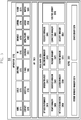
- the programming module 310 may be included (or stored) in the electronic device 100 (e.g., the memory 130) or may be included (or stored) in the electronic device 201 (e.g., the memory 230) illustrated in FIG. 1 . At least a part of the programming module 310 may be implemented in software, firmware, hardware, or a combination of two or more thereof.
- the programming module 310 may be implemented in hardware (e.g., the hardware 200), and may include an OS controlling resources related to an electronic device (e.g., the electronic device 100) and/or various applications (e.g., an application 370) executed in the OS.
- the OS may be ANDROID, iOS, WINDOWS, SYMBIAN, TIZEN, BADA, and the like.
- the programming module 310 may include a kernel 320, a middleware 330, an API 360, and/or the application 370.
- the kernel 320 may include a system resource manager 321 and/or a device driver 323.
- the system resource manager 321 may include, for example, a process manager (not illustrated), a memory manager (not illustrated), and a file system manager (not illustrated).
- the system resource manager 321 may perform the control, allocation, recovery, and/or the like of system resources.
- the device driver 323 may include, for example, a display driver (not illustrated), a camera driver (not illustrated), a BLUETOOTH driver (not illustrated), a shared memory driver (not illustrated), a USB driver (not illustrated), a keypad driver (not illustrated), a Wi-Fi driver (not illustrated), and/or an audio driver (not illustrated).
- the device driver 323 may include an inter-process communication (IPC) driver (not illustrated).
- IPC inter-process communication
- the middleware 330 may include at least one of a runtime library 335, an application manager 341, a window manager 342, a multimedia manager 343, a resource manager 344, a power manager 345, a database manager 346, a package manager 347, a connectivity manager 348, a notification manager 349, a location manager 350, a graphic manager 351, a security manager 352, and any other suitable and/or similar manager.
- the application manager 341 may manage, for example, a life cycle of at least one of the applications 370.
- the window manager 342 may manage GUI resources used on the screen.
- the multimedia manager 343 may detect a format used to reproduce various media files and may encode or decode a media file through a codec appropriate for the relevant format.
- the resource manager 344 may manage resources, such as a source code, a memory, a storage space, and/or the like of at least one of the applications 370.
- the power manager 345 may operate together with a basic input/output system (BIOS), may manage a battery or power, and may provide power information and the like used for an operation.
- the database manager 346 may manage a database in such a manner as to enable the generation, search and/or change of the database to be used by at least one of the applications 370.
- the package manager 347 may manage the installation and/or update of an application distributed in the form of a package file.
- the connectivity manager 348 may manage a wireless connectivity such as, for example, Wi-Fi and Bluetooth.
- the notification manager 349 may display or report, to the user, an event such as an arrival message, an appointment, a proximity alarm, and the like in such a manner as not to disturb the user.
- the location manager 350 may manage location information of the electronic device.
- the graphic manager 351 may manage a graphic effect, which is to be provided to the user, and/or a user interface related to the graphic effect.
- the security manager 352 may provide various security functions used for system security, user authentication, and the like.
- the middleware 330 may further include a telephony manager (not illustrated) for managing a voice telephony call function and/or a video telephony call function of the electronic device.
- a telephony manager not illustrated for managing a voice telephony call function and/or a video telephony call function of the electronic device.
- the middleware 330 may generate and use a new middleware module through various functional combinations of the above-described internal element modules.
- the middleware 330 may provide modules specialized according to types of OSs in order to provide differentiated functions.
- the middleware 330 may dynamically delete some of the existing elements, or may add new elements. Accordingly, the middleware 330 may omit some of the elements described in the various embodiments of the present disclosure, may further include other elements, or may replace the some of the elements with elements, each of which performs a similar function and has a different name.
- the API 360 (e.g., the API 145) is a set of API programming functions, and may be provided with a different configuration according to an OS. In the case of Android or iOS, for example, one API set may be provided to each platform. In the case of TIZEN, for example, two or more API sets may be provided to each platform.
- the applications 370 may include, for example, a preloaded application and/or a third party application.
- the applications 370 may include, for example, a home application 371, a dialer application 372, a short message service (SMS)/multimedia message service (MMS) application 373, an instant message (IM) application 374, a browser application 375, a camera application 376, an alarm application 377, a contact application 378, a voice dial application 379, an electronic mail (e-mail) application 380, a calendar application 381, a media player application 382, an album application 383, a clock application 384, and any other suitable and/or similar application.
- SMS short message service
- MMS multimedia message service
- IM instant message
- At least a part of the programming module 310 may be implemented by instructions stored in a non-transitory computer-readable storage medium. When the instructions are executed by one or more processors (e.g., the one or more processors 210), the one or more processors may perform functions corresponding to the instructions.
- the non-transitory computer-readable storage medium may be, for example, the memory 230.
- At least a part of the programming module 310 may be implemented (e.g., executed) by, for example, the one or more processors 210.
- At least a part of the programming module 310 may include, for example, a module, a program, a routine, a set of instructions, and/or a process for performing one or more functions.
- Names of the elements of the programming module may change depending on the type of OS.
- the programming module according to an embodiment of the present disclosure may include one or more of the above-described elements. Alternatively, some of the above-described elements may be omitted from the programming module. Alternatively, the programming module may further include additional elements.
- the operations performed by the programming module or other elements according to an embodiment of the present disclosure may be processed in a sequential method, a parallel method, a repetitive method, or a heuristic method. Also, some of the operations may be omitted, or other operations may be added to the operations.
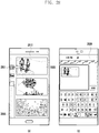
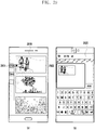
- the instructions enable the processor to: display the first user interface on the first image-display area; display text or icons related to the second application on the third image-display area; receive a first user input for selecting an item or action via the first image-display area; receive, when the first user input is received, a second user input for selecting the text or the icon via the third image display area; and display the second user interface on the second image-display area, in response to the second user input, and process the item or action, using the second application.
- the first application includes a photo gallery application.
- the second application includes at least one message/email sending application. At least one of the third image-display areas extends from the edge of the first image-display area to the edge of the second image-display area.
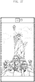
- the second user input includes: a user action for dragging an object located in the first image-display area to the text or the icons located in the second image-display area.
- the second user input includes: a user action for dragging the text or the icons located in the second image-display area to an object located in the first image-display area.
- the instructions enable the processor to perform, when executing the second application, linkify to link an object located in the first image-display area with the second image-display area running the second application.
- the instructions enable the processor to: switch a first screen displayed on the first image-display area to a second screen in response to a third user input; and display the first screen on the second image-display area, when switching the first screen to the second screen on the first image-display area.
- the instructions enable the processor to allow the first and second image-display areas to display: screens on which the same application is running; and the same information included in the execution screens in different forms, respectively.
- the instructions enable the processor to allow the first and second image-display areas to display screens on which the same application is running, wherein information of the execution screen shown on the first image-display area is shown on the second image-display area.
- the second display 420 facing a second direction is mounted on the rear side of the electronic device.
- the second direction is opposite the first direction.
- the electronic device may include a camera 421 and a flash 422 for taking images at the top above the second display 420.
- the electronic device includes a third display 430 and fourth display 440 at both sides, respectively.
- the third and fourth displays 430 and 440 may be extended from the first display 410 or the second display 420.
- the first to fourth display 410, 420, 430, and 440 may be continuously connected to each other.
- Fig. 5 is a cross-sectional view of an electronic device according to various embodiments of the present invention.
- Fig. 5 is a cross-sectional view of an electronic device shown in Fig. 4 .
- the electronic device may be protected by a hosing 552 as a casing member.
- the housing 552 encases parts of the electronic device therein.
- the housing 552 is configured to form a hollow space receiving an operation circuit, a power circuit, a communication circuit, a battery 551, etc., related to the operations of the electronic device.
- the operation circuit and the power circuit may be implemented on a printed circuit board (PCB) 553.
- PCB printed circuit board
- the outer surface of the housing 552 includes: a first side that faces a first direction and is covered by a first display 510; a second side that faces a second direction and is covered by a second display 520; sides each of which encloses parts between the first and second sides and each of which are covered by third and fourth displays 530 and 540, respectively.
- the first to fourth display 510, 520, 530, and 540 of the outer surface of the housing 552 may be continuously connected to each other. Therefore, the electronic device includes the first image-display area on the first side, the second image-display area on the second side, and the third image-display areas on the sides.
- the housing 552 includes a bezel 541, on the side covered by the fourth display 540, for dividing the fourth display 540 into two parts.
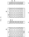
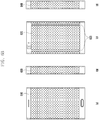
- Figs. 6A to 6C show diagrams of the outward appearance of an electronic device according to various embodiments of the present invention.
- an electronic device is capable of including third and fourth displays 630 and 640 on both sides, each of which is formed to be divided into two parts.
- the electronic device is capable of including the third display 630 on one side.
- the third display 630 may be formed in such a way that the first and second displays 610 and 620 extend to one side, respectively.
- the third display 630 is split into two parts by a first bezel 631 in the lengthwise direction.
- the electronic device is capable of including the fourth display 640 on the other side.
- the fourth display 640 may be formed in such a way that the first and second displays 610 and 620 extend to the other side, respectively.
- the fourth display 640 is split into two parts by a second bezel 641 in the lengthwise direction.
- an electronic device includes displays on a front side, a rear side, and one of the sides.
- the electronic device includes: a first display 610 on the front side and a second display 620 on the rear side as shown in Fig. 6C ; and a third display 630 on one of both sides as shown in diagram (b) of Fig. 6C .
- the electronic device may not include a display on the other side 650 of both sides.
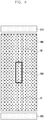
- Fig. 7 is a detailed cross-sectional view of an electronic device according to various embodiments of the present disclosure.
- the bent part of the middle frame 720 is a part (parts) at one or more side ends of the middle frame 720, which is (are) slidably coupled to the rail member 750 and fitted into the groove 741 of the side frame 740.
- the bent part of the middle frame 720 is designed in such a way that the end of the middle frame 720 is bent at least two times and forms a step at the end of the flat part supporting the display 710. It should be understood that the bent part may be implemented in various forms. Since the electronic device according to an embodiment includes the rail member 750 into which the bent part of the middle frame 720 is slidably fitted from the end, it can be easily assembled, and this leads to increase the productivity and yield.
- Fig. 8 is a diagram showing the configuration of an electronic device according to various embodiments of the present disclosure. More specifically, Fig. 8 is a side view of an electronic device.
- an electronic device is capable of including at least one hole (obstacle) 830 inside an image-display area of a display 805.
- the hole 830 may be an obstacle to dispose a user input button.
- an electronic device may be designed in such a way that a display 805 is disposed on at least one side and a user input button is formed on the side where the display 805 is disposed.
- the user input button may be disposed in the hole 830 formed inside the image-display area of the display 805.
- the electronic device is designed in such a way that: a display 805 with a hole 830 is located at one side (front/rear) of the electronic device and an operation circuit 820 for driving the display 805 is located at the bottom (or top) of the display 805.
- the display 805 includes a number of signal lines in a matrix form for providing video data output from the operation circuit 820 to a number of pixels. In this case, part of the signal lines, between the hole 830 and the operation circuit 820, do not maintain the linearity, which is because the hole 830 serves as an obstacle.
- the display 805 may show a video on a first region A1 where the hole 830 and the operation circuit 820 face each other on the strait line between the hole 830 and the operation circuit 820 because the linearity of the signal lines is maintained; however, the display 805 may not show a video on a second region A2 that corresponds to the other region, except for the first region A1, because the linearity of the signal lines is not maintained by the hole 830.
- the first region A1 is referred to as a region that is located between the top end of the display 805 and the hole 830 on the straight line in which the hole 830 and the operation circuit 820 face each other. If the operation circuit 820 is located at the top of the display 805, the first region A1 and the second region A2 may change their locations with each other.
- the electronic device may be implemented in such a way that operation circuits are installed to both of the top and bottom of the display 805 and take charge of the display on the first and second regions A1 and A2, respectively.
- the electronic device includes: a first operation circuit 820 at the bottom of the display 805 so that the first operation circuit 820 can drive an image-display area corresponding to the first region A1; and a second operation circuit 810 at the top of the display 805 so that the second operation circuit 810 can drive an image-display area corresponding to the second region A2.
- the electronic device may allow one of the first and second operation circuits 810 and 820 to drive an image-display area corresponding to the remaining region, except for the first and second regions A1 and A2.
- the electronic device Since the electronic device according to an embodiment is implemented to include operation circuits 810 and 820 for operation the display 805 at the top and bottom of the display 805 respectively, although a hole 830 is formed inside an image-display area of the display 805, the electronic device is capable of displaying a video on all the region except for the hole 830.
- Fig. 9 shows diagrams that describe a metal key of an electronic device according to various embodiments of the present disclosure.
- Fig. 10 is a detailed diagram of a metal key of an electronic device according to various embodiments of the present disclosure.
- an electronic device 900 may be designed in such a way that a user operation button (user operation buttons) is (are) included in at least one side of the housing.
- the housing of the electronic device 900 may be made of a metal material.
- the user operation button may be formed as a non-protrusion structure.
- the electronic device 900 includes a bezel 910 in at least one of the sides of the housing, for dividing the display extended, in the side direction, from an edge of the front side or rear side, into two displays in the lengthwise of the display.
- the bezel 910 may be made of a metal material.
- the bezel 910 includes at least one user operation button.
- the user operation button may be formed in non-protrusion structure. As shown in diagram (b) of Fig. 9 , the user operation button may be implemented to include: an insulator 930 formed in part of the bezel 910; and a metal key 920 that is formed inside the insulator 930 and spaced apart from the metal material of the bezel 910.
- the insulator 930 may be shaped in circle or polygon. Part of the margin of the bezel 910 may be formed at both sides of the insulator 930. Therefore, the bezel 910 may have a non-division form in a region where the user operation button is located.
- the user operation button detects a user input via mutual capacitance.
- the metal key 920 is designed in a single layer or double layers.
- the metal key 920 is designed in a single layer. As shown in diagram (d) of Fig. 9 , the metal key 920 is designed in double layers further including a second metal key 925 that is located below the metal key 920 and overlaps the metal key 920, seen from the top.
- an electronic device may be designed in such a way that a bezel is divided by a user operation button.
- the user operation button may include a number of insulators 1030 configured to divide the bezel into parts in the width direction.
- the user operation button may include: a first insulator in a region, for dividing a bezel into two parts in the width direction; a second insulator spaced apart from the first insulator, for dividing the bezel into two parts in the width direction; and a metal key 1020 located between the first and second insulators.
- a method of operating an electronic device is implemented to include: executing a first application, and displaying a first user interface on a first image-display area; displaying text or icons related to a second application on a third image-display area; receiving a first user input for selecting an item or action via the first image-display area; receiving, when receiving the first user input, a second user input for selecting the text or the icon via the third image-display area; and displaying the second user interface on the second image-display area, in response to the second user input, and processing the item or action, using the second application.
- the first application includes a photo gallery application.
- the second application includes at least one message/email sending application.
- the reception of a second user input includes: receiving a user action for dragging an object located in the first image-display area to the text or the icons located in the second image-display area.
- the reception of a second user input includes: receiving a user action for dragging the text or the icons located in the second image-display area to an object located in the first image-display area.
- the method may further include: performing, when executing the second application, linkify to link an object located in the first image-display area with the second image-display area running the second application.
- the method may further include: switching a first screen displayed on the first image-display area to a second screen in response to a third user input; and displaying the first screen on the second image-display area, when switching the first screen to the second screen on the first image-display area.
- the method may further include allowing the first and second image-display areas to display: screens on which the same application is running; and the same information included in the execution screens in different forms, respectively.
- the method may further include: allowing the first and second image-display areas to display screens on which the same application is running, wherein information of the execution screen shown on the first image-display area is shown on the second image-display area.
- the method may further include: executing a third application in response to a user input; and allowing the first to third image-display areas to display corresponding partial screens of a single screen, respectively, and displaying the single screen formed as the partial screens shown on the first to third image-display areas are successively connected to each other.
- the third application includes: a map search application and/or a photo gallery application.
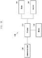
- Fig. 11 is a block diagram of an electronic device according to various embodiments of the present disclosure.
- an electronic device is capable of including a display 1120, a communication circuit 1150, an input unit 1130, a memory 1140, and a processor 1110.
- the display 1120 (e.g., display 260) is capable of displaying data/information input by a user and provided to the user, as well as various menus for the electronic device 1100.
- the display 1120 is capable of providing various types of screens according to the operations of the electronic device 1100, such as an idle screen (home screen), menu screens, a message writing screen, a call screen, schedule management screen, contacts screen, web-page output screens, etc.
- the display 1120 may be implemented with a liquid crystal display (LCD), organic light emitting diodes (OLEDs), active matrix organic light emitting diodes (AMOLEDs), or the like.
- OLEDs organic light emitting diodes
- AMOLEDs active matrix organic light emitting diodes
- the display 1120 may be formed to enclose the sides of the electronic device, including a number of image-display areas corresponding to the sides.
- the display 1120 includes: a first display on the front side (e.g., first side) of the electronic device; a second display on the rear side (e.g., second side) of the electronic device; and a third display (third displays) on a side (sides) of the electronic device.
- An area displaying a video via the first display is defined as a first image-display area.
- An area displaying a video via the second display is defined as a second image-display area.
- An area displaying a video via the third display is defined as a third image-display area.
- the first to third displays is capable of operating independently, respectively, under the control of the processor 1110, displaying different videos or successive parts of a video.
- the first to third displays may display videos in various modes according to the method of operating an electronic device, which will be described in detail later.
- the communication circuit 1150 (e.g., communication module 220) establishes, with a base station, a communication cannel for a call (e.g., a voice call, a video call, etc.) and a data communication channel for the transmission of data.
- the communication circuit 1150 includes: an RF transmitter for up-converting the frequency of signals to be transmitted and amplifying the signals, an RF receiver for low-noise amplifying received RF signals and down-converting the frequency of the received RF signals, a transmission/reception separator for separating transmission signals and reception signals, etc.
- the input unit 1130 (e.g., input unit 250) includes input keys and function keys that receive numerical or alphabetical information and set and control a variety of functions in the electronic device 1100.
- the input unit 1130 may be implemented with one of the following: a button-type key pad, a ball joystick, an optical joystick, a wheel key, a touch key, a touch pad, a touch screen, etc., or a combination thereof.
- the memory 1140 (e.g., memory 230) is capable of storing: an operating system (OS) of the electronic device 1100; applications required for option functions, e.g., an audio playback function, image/video playback function, broadcast playback function, etc.; user data, data transmitted during the communication, etc.
- OS operating system
- the memory 1140 is capable of storing video files, game files, music files, movie files, etc.
- the processor 1110 controls the entire operation of the electronic device 1100 and the signals between the components in the electronic device 1100.
- the processor 1110 also performs a data process function.
- the processor 1110 may be a central processing unit (CPU), a micro-processor unit (MPU), an application processor (AP), etc.
- the processor 1110 is capable of executing an application, providing a user interface via a display, and controlling the first to third displays to show screens in response to user inputs.
- the following description provides a detailed description regarding a method for a processor to control the first to third displays to show screens.
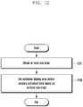
- Fig. 12 is a flowchart that describes operations of an electronic device according to various embodiments of the present disclosure.
- the electronic device is capable of simultaneously using activated areas of the display. Alternatively, the electronic device is also capable of controlling activated areas, independently, respectively.
- the processor e.g., the application processor 210 shown in Fig. 2
- the processor is capable of detecting at least one input in operation 1201.
- at least one input may be created by various types of input units of the electronic device (e.g., the electronic device 101 shown in Fig. 1 ).
- At least one input may be information obtained from at least one sensor (e.g., the sensor module 240 shown in Fig. 2 ).
- At least one input may be a signal received from external systems, e.g., an incoming call signal, a message reception signal, etc.
- At least one input may also include a start operation of a pre-defined application.
- the application processor 210 is capable of setting an activated display area based on at least one input in operation 1203.
- Fig. 13 is a flowchart that describes a method 1302 of setting an activated display area, based on at least one input, according to various embodiments of the present disclosure.
- Figs. 14 and 15 show diagrams that describe operations of an electronic device adapted to the method of the flowchart as shown in Fig. 13 , according to an embodiment of the present disclosure.
- the processor e.g., the application processor 210 shown in Fig. 2
- the processor is capable of detecting the wake-up signal in operation 1301.
- a wake-up signal may be generate by pressing a button, by inputting a pre-defined type of touch, and/or by applying a hovering input, etc.
- a wake-up signal may be a signal detected by at least one sensor.
- a wake-up signal may be an incoming call signal, the reception of a text message or a social network service (SNS) message, etc.
- SNS social network service
- the application processor 210 is capable of setting the first activated display area in operation 1303.
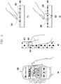
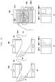
- FIG. 14 With reference to diagram (a) of Fig. 14 , if an electronic device 1400 is placed on a flat so that the front side faces upward, the first side 1411 is exposed but the second side 1412 is not exposed. If a hovering input or a touch input, such as a flick gesture, a double tap, etc., is applied to a first display area 1460-1 of the first side 1411, the screen of the first display area 1460-1 is unlocked and displays corresponding content 1440.
- a hovering input or a touch input such as a flick gesture, a double tap, etc.
- the application processor 210 is capable of detecting the pre-defined input in operation 1307. For example, as shown in diagram (a) of Fig. 15 , when the user grips the electronic device 1400 with the hand 14, part of the user's hand 14 may continuously apply the touch or hovering input to the display 1460, and this may generate a pre-defined input.
- the application processor 210 measures a turn angle of the electronic device 1400, and determines whether the turn angle is greater than a threshold in operation 1313. If the application processor 210 ascertains that the turn angle is greater than a threshold in operation 1313, it is capable of setting a second activated display area in operation 1309. For example, as shown in diagram (b) of Fig. 14 , if the electronic device 1400 is turned over from the position shown in diagram (a) of Fig. 14 , so that the second side 1412 is disclosed and the first side 1411 is disclosed, the application processor 210 ascertains that the turn angle of the electronic device is greater than a threshold. The application processor 210: switches the first display area 1460-1 from an activated state to an inactivated state, and the second display area 1460-2 from an inactivated state to an activated state; and displays the content 1440 on the second display area 1460-2.
- the application processor 210 is capable of setting a second activated display area in operation 1309. For example, as shown in diagrams (b) and (c) of Fig. 15 , if the user grips the electronic device 1400, part of the user's hand 14 may apply the touch or hovering input to first display area 1460-1 of the display 1460, and this may generate a pre-defined input.
- the application processor 210 switches the first display area 1460-1 from an activated state to an inactivated state, and the second display area 1460-2 from a de-activate state to an activated state; and displays the content 1440 on the second display area 1460-2.
- the application processor 210 is capable of setting a third activated display area in operation 1303 or 1309.
- the activated area and the inactivated area in the third display area 1460-3 may be adjusted according to the content displayed on the first display area 1460-1 or the second display area 1460-2.
- the application processor 210 is capable of activating part of a third display area 1460-3 by the size of the content 1440 and inactivating the remaining part of the third display area 1460-3.
- the third display area 1460-3 may be separated from the display via an inactivated area or physically as shown in Fig. 6A or 6B .
- the display 1460 shown in Fig. 14 may further include an additional display area of a fourth display area 1460-4 or fifth display area 1460-5.
- the application processor 210 is capable of activating part of the fourth display area 1460-3 or fifth display area 1460-5 by the size of the content 1440 and inactivating the remaining part of the fourth display area 1460-4 or fifth display area 1460-5.
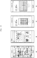
- Fig. 16 shows diagrams of various types of screen provided by an electronic device according to various embodiments of the present disclosure.
- Fig. 17 shows diagrams of a background screen provided by an electronic device according to various embodiments of the present disclosure.
- Fig. 18 shows diagrams that describe a method of operating an electronic device according to various embodiments of the present disclosure.
- Fig. 19 shows diagrams that describe a method for an electronic device to provide an incoming call notification according to various embodiments of the present disclosure.
- Fig. 20 shows diagrams that describe a method for an electronic device to provide an incoming call notification according to various embodiments of the present disclosure.
- Fig. 21 shows diagrams of screens provided by an electronic device according to various embodiments of the present disclosure.
- Fig. 21 shows diagrams of screens provided by an electronic device according to various embodiments of the present disclosure.
- FIG. 22 shows diagrams of screens provided by an electronic device according to various embodiments of the present disclosure.
- Fig. 23 shows diagrams of screens when an electronic device runs a media playback application according to various embodiments of the present disclosure.
- Fig. 24 shows diagrams of screens when an electronic device runs a clock application according to various embodiments of the present disclosure.
- Fig. 25 shows diagrams of idle screens when an electronic device operates in an idle mode according to various embodiments of the present disclosure.
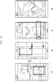
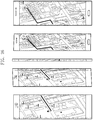
- Fig. 26 shows diagrams of screens when an electronic device runs a map search application according to various embodiments of the present disclosure.
- the processor 1110 executes one of a number of applications stored in the memory 1140, referring to the memory 1140, and provides a user interface to at least one display.
- first, second and third applications may include first, second and third user interfaces respectively.
- the processor 1110 is capable of executing one of the applications, and providing different user interface screens to first to third displays, respectively.
- the processor 1110 controls the first and second displays to display: screens on which the same application is running; and the same information included in the execution screens in different forms, respectively.
- an example of the application executed by the processor 1110 is a web-browser.
- the processor 1110 executes a web-browser and controls the first and second displays to display web screens respectively.
- the processor 1110 may allow the first and second displays to show the web-browser screens in different forms respectively.
- the processor 1110 may provide a web screen of a "PC version" to the first display of the front side of the electronic device.
- the processor 1110 may provide a web screen of a "mobile version" to the second display of the rear side of the electronic device.
- Another example of the application executed by the processor 1110 is a calculator application.
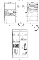
- the processor 1110 executes a calculator application and controls the first and second displays to display calculator screens respectively. In this case, the processor 1110 may allow the first and second displays to show the calculator screens in different forms respectively. For example, as shown in diagram (c) of Fig.
- the processor 1110 may provide a calculator screen of a "basic calculator” form to the first display of the front side of the electronic device.
- the processor 1110 may provide a calculator screen of a "scientific calculator” form to the second display of the rear side of the electronic device.
- the processor 1110 is capable of controlling the first and second displays to display background screens (home screens) that differ from each other, respectively.
- the processor 1110 controls the first display to display a background screen of a first type.
- the processor 1110 also controls the second display to display a background screen of a second type.
- the background screen of a first type may be a default home screen provided by smartphone manufacturers.
- the background screen of a first type may show icons corresponding to a number of applications and a folder containing at least one icon.
- the background screen of a second type may be a screen provided when a smartphone runs in an easy mode.
- the background screen of a second type may show icons larger in size and less in number than the background screen of a first type.
- the background screen of a second type may only show icons corresponding to frequently used applications, e.g., a call function, a camera function, an Internet function, a messenger function, etc.
- the electronic device according to an embodiment is capable of displaying a user interface provided by one application on multiple displays in various modes that differ from each other, thereby increasing user convenience.
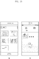
- the processor 1110 is capable of executing one of a number of applications, switching a screen displayed on a display (display 1) in response to a user input, and performing, when the screen displayed on the display (display 1) is switched, a control operation so that a screen previously displayed on the display (display 1) can be displayed on another display.
- the application execute by the processor 1110 may be a web-browser.
- the processor 1110 is capable of providing: a first web screen 1801 of the web-browser executed on the first display, and a first user interface; and a second web screen 1802 on the second display.
- the screen displayed on the second display may not be a second web screen, but may be a second user interface according to the execution of another application.
- the processor 1110 is capable of switching: a first web screen 1801 displayed on the first display into a third web screen 1803; and a second web screen 1802 displayed on the second display into the first web screen 1801. While a web screen is switched on the first display, if the second display provides a second user interface according to the execution of another application, the processor 1110 is capable of performing a control operation so that the second display can provide a previous screen of the first display from the second user interface.
- the electronic device according to an embodiment is capable of controlling, using a multiple display device, one display to display a previous screen provided by another display, thereby increasing user convenience.
- the processor 1110 when the electronic device receives a call, the processor 1110 provides a notification of an incoming call to a first or second display.
- the processor 1110 may also provide a notification of an incoming call in other mode.
- the processor 1110 may provide a notification in various modes according to positions (postures) of an electronic device.
- FIG (a) of Fig. 19 when the electronic device is placed so that the first display faces upwards and the second display faces downwards, the processor 1110 is capable of displaying a caller's phone number and information regarding the caller on the first display, and also providing a ringtone or a vibration notification.
- the processor 1110 when the electronic device is placed so that the first display faces downwards and the second display faces upwards, the processor 1110 is capable of displaying only a caller's phone number on the second display, without providing a ringtone and a vibration notification.
- the processor 1110 is capable of: providing a caller's phone number and information regarding the caller to the first display; and controlling the second display to display a screen previously displayed on the first display.
- the processor 1110 when the electronic device receives a call while the user is using an application "SMON", the processor 1110 is capable of displaying; a caller's phone number and information regarding the caller on the first display as shown in diagram (a) of Fig. 20 .
- the processor 1110 is capable of displaying a user interface of the application "SMON", previously displayed on the first display before receiving the call, on the second display as shown in diagram (b) of Fig. 20 .
- the user can resume using the application that the user has used via the second display.
- the processor 1110 is capable of controlling one display to display information of a screen currently displayed on another display.
- the processor 1110 is capable of: executing one of a number of applications; providing a first user interface to one display; and controlling one display to display information of the first user interface on another display, via the first user interface, in response to a user input.
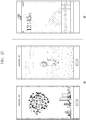
- the processor 1110 is capable of executing a map search application and providing a map screen to the first display.
- the processor 1110 receives and detects a user input selecting a specified region on the first display via the first user interface, and displays a detailed map screen corresponding to the specified region on the second display.
- the user input selecting a specified region may be one or more of the following: a single touch, a multi touch, a tap/touch, and a pressure touch.
- a single touch For example, when a user needs to zoom in on a location where a terminal is located on the map screen on the first display, the user may apply multi-touches to the location where the terminal is located on the map screen.
- the processor 1110 detects the multi-touches, identifies the multi-touched region, and displays a map enlarging the location on the second display.
- the processor 1110 is capable of executing a destination search application, and displaying, on the first display, a screen providing offered paths according to the destination search.
- the processor 1110 receives and detects a user input selecting one of the offered paths on the first display, via the first user interface, and displays the selected, offered path, in detail, on the second display.
- the processor 1110 is capable of executing a dictionary search application.
- the processor 1110 is capable of providing the first display with a list of words according to the dictionary search result.
- the processor 1110 is capable of detecting a user input selecting one of the words on list on the first display via a first user interface.
- the processor 1110 receives the user input, it is capable of providing the user's selected word, the definition, the related words, etc., to the second display.
- the processor 1110 may execute various applications as well as the map search application, the destination search application, and the dictionary search application; and may enable one of a number of displays to display information or information related to a screen previously provided to another display.
- the processor 1110 is capable of executing a media playback application.
- the processor 1110 is capable of executing a media playback application and providing a playlist to the first display.
- the processor 1110 is capable of providing the second display with shortcut keys for controlling media playback (e.g., a hot key).
- the shortcut keys may include a number of buttons: previous, next, paly, pause, stop, etc., and an album jacket, etc.
- the processor 1110 may also control the second display to provide preset shortcut keys, e.g., shortcut keys for providing a camera function, a picture-memo function, etc.
- the processor 1110 is capable of executing a clock application.
- the processor 1110 is capable of executing a clock application according to a user input or when the electronic device is in a screen-lock sate (or an idle mode).
- the processor 1110 is capable of displaying clock information in one form on the first display and in another form on the second display.
- the processor 1110 is capable of providing the first and second displays with the clock images that differ in design and color from each other.
- the processor 1110 is capable of displaying an analog clock on the first display and a digital clock on the second display.
- the processor 1110 is capable of displaying an analog clock on both of the first and second displays.
- the processor 1110 may set the analog clocks displayed on the first and second displays to differ from each other in outer border, background, hand, or size. As shown in diagrams (c) and (d) of Fig. 24 , the processor 1110 is capable of providing the same screen to the first and second displays.
- the processor 1110 is capable of displaying successive screens on a number of displays.
- the processor 1110 is capable of executing an application in response to a user input, and displaying parts of one screen of the executed application, successively, on first to third displays.
- the processor 1110 is capable of executing a map search application.
- the processor 1110 is capable of displaying parts of the map screen created according to the map search application, successively, on the first to third displays.
- the processor 1110 is capable of dividing a specified local area on the map into a number of areas.
- the electronic device is capable of displaying, on one of a number of displays/display areas, information of a screen currently displayed another display/display area, thereby providing user convenience.
Landscapes
- Engineering & Computer Science (AREA)
- Theoretical Computer Science (AREA)
- General Engineering & Computer Science (AREA)
- Physics & Mathematics (AREA)
- General Physics & Mathematics (AREA)
- Human Computer Interaction (AREA)
- Computer Hardware Design (AREA)
- Software Systems (AREA)
- Computer Graphics (AREA)
- Microelectronics & Electronic Packaging (AREA)
- Signal Processing (AREA)
- User Interface Of Digital Computer (AREA)
- Telephone Function (AREA)
Claims (10)
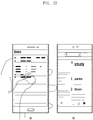
- Elektronische Vorrichtung (100), umfassend:ein Gehäuse (552), das folgendes aufweist:eine Vorderseite (1411), die in eine erste Richtung zeigt;eine Rückseite (1412), die in eine zu der ersten Richtung entgegengesetzte zweite Richtung zeigt; undeine Seitenfläche, die auf mindestens einer Seite der Vorder- und Rückseite angeordnet ist;ein Display (160), das folgendes aufweist:einen ersten Bildanzeigebereich (410) auf der Vorderseite (1411);einen zweiten Bildanzeigebereich (420) auf der Rückseite (1412); undeinen dritten Bildanzeigebereich (430) auf der Seitenfläche;eine Kommunikationsschaltung (1150), die für eine Ausführung einer Funkkommunikation mit einer externen Vorrichtung (102) gestaltet ist;einen Prozessor (120), der sich in dem Gehäuse befindet und mit dem Display und der Kommunikationsschaltung elektrisch verbunden ist; undeinen Speicher (130), der sich in dem Gehäuse befindet, mit dem Prozessor elektrisch verbunden ist und zum Speichern von Anweisungen gestaltet ist, die bewirken, dass der Prozessor eine erste Applikation (147) mit einer ersten Benutzeroberfläche und eine zweite Applikation (147) mit einer zweiten Benutzeroberfläche ausführt;wobei der Speicher (130) ferner so gestaltet ist, dass er Anweisungen speichert, die bewirken, dass der Prozessor folgendes ausführt:Anzeigen der ersten Benutzeroberfläche in dem ersten Bildanzeigebereich, während die erste Applikation ausgeführt wird;Anzeigen von Text oder Symbolen (2801), die sich auf die zweite Applikation beziehen, in dem dritten Bildanzeigebereich;Empfangen einer ersten Benutzereingabe zur Auswahl eines Objekts (2803) über den ersten Bildanzeigebereich;während die erste Benutzereingabe empfangen wird, Empfangen einer zweiten Benutzereingabe des Ziehens des sich in dem ersten Bildanzeigebereich befindenden Objekts (2803) auf den Text oder die Symbole, die sich in dem dritten Bildanzeigebereich befinden;als Reaktion auf die zweite Benutzereingabe, Ausführen der zweiten Applikation (147) zum Anzeigen der zweiten Benutzeroberfläche in dem zweiten Bildanzeigebereich; undEinsetzen des sich in dem ersten Bildanzeigebereich befindenden Objekts (2803) in die zweite Benutzeroberfläche.
- Elektronische Vorrichtung nach Anspruch 1, wobei:die erste Applikation eine Fotogalerie-Applikation umfasst; unddie zweite Applikation mindestens eine Applikation zum Verschicken von Nachrichten oder eine Applikation zum Verschicken von E-Mails umfasst.
- Elektronische Vorrichtung nach Anspruch 1, wobei der Speicher (130) ferner so gestaltet ist, dass er Anweisungen speichert, die bewirken, dass der Prozessor folgendes ausführt:Wechseln von einem in dem ersten Bildanzeigebereich angezeigten ersten Bildschirm zu einem zweiten Bildschirm als Reaktion auf eine dritte Benutzereingabe; undAnzeigen des ersten Bildschirms in dem zweiten Bildanzeigebereich, wenn in dem ersten Bildanzeigebereich von dem ersten Bildschirm zu dem zweiten Bildschirm gewechselt wird.
- Elektronische Vorrichtung nach Anspruch 1, wobei der Speicher (130) ferner so gestaltet ist, dass er Anweisungen speichert, die bewirken, dass der Prozessor den ersten und zweiten Bildanzeigebereich so steuert, dass diese folgendes anzeigen: Bildschirme, auf denen die gleiche Applikation ausgeführt wird; und wobei entsprechend die gleichen Informationen in den ausgeführten Bildschirmen in verschiedenen Formaten enthalten sind.
- Elektronische Vorrichtung nach Anspruch 1, wobei der Speicher (130) ferner so gestaltet ist, dass er Anweisungen speichert, die bewirken, dass der Prozessor den ersten und zweiten Bildanzeigebereich so steuert, dass Bildschirme angezeigt werden, auf denen die gleiche Applikation ausgeführt wird, wobei Informationen des ausführenden Bildschirms, der in dem ersten Bildanzeigebereich angezeigt wird, in dem zweiten Bildanzeigebereich angezeigt werden.
- Elektronische Vorrichtung nach Anspruch 1, wobei der Speicher (130) ferner so gestaltet ist, dass er Anweisungen speichert, die bewirken, dass der Prozessor folgendes ausführt:Ausführen einer dritten Applikation (147) als Reaktion auf eine Benutzereingabe;Steuern des ersten bis dritten Bildanzeigebereichs, so dass diese demgemäß entsprechende Teilbildschirme eines einzelnen Bildschirms anzeigen; undAnzeigen des einzelnen Bildschirms, der gebildet wird, wenn die in dem ersten bis dritten Bildanzeigebereich angezeigten Teilbildschirme nacheinander miteinander verbunden werden.
- Elektronische Vorrichtung nach Anspruch 6, wobei die dritte Applikation folgendes umfasst:
eine Kartensuchapplikation oder eine Fotogalerie-Applikation. - Verfahren für den Betrieb einer elektronischen Vorrichtung (100), die folgendes aufweist: ein Gehäuse (552), das folgendes aufweist: eine Vorderseite (1411), die in eine erste Richtung zeigt, eine Rückseite (1412), die in eine zu der ersten Richtung entgegengesetzte zweite Richtung zeigt, und eine Seitenfläche, die auf mindestens einer Seite der Vorder- und Rückseite angeordnet ist; und ein Display (160), das einen ersten Bildanzeigebereich (410) auf der Vorderseite aufweist, einen zweiten Bildanzeigebereich (420) auf der Rückseite und einen dritten Bildanzeigebereich (430) auf der Seitenfläche, wobei das Verfahren folgendes umfasst:Ausführen einer ersten Applikation (147) und Anzeigen einer ersten Benutzeroberfläche in dem ersten Bildanzeigebereich;Anzeigen von Text oder Symbolen (2801), die sich auf eine zweite Applikation (147) beziehen, in dem dritten Bildanzeigebereich;Empfangen einer ersten Benutzereingabe zur Auswahl eines Objekts (2803) über den ersten Bildanzeigebereich;während die erste Benutzereingabe empfangen wird, Empfangen einer zweiten Benutzereingabe des Ziehens des sich in dem ersten Bildanzeigebereich befindenden Objekts (2803) auf den Text oder die Symbole, die sich in dem dritten Bildanzeigebereich befinden;als Reaktion auf die zweite Benutzereingabe: Ausführen der zweiten Applikation (147), Anzeigen einer zweiten Benutzeroberfläche in dem zweiten Bildanzeigebereich und Einsetzen des sich in dem ersten Bildanzeigebereich befindenden Objekts (2803) in die zweite Benutzeroberfläche.
- Verfahren nach Anspruch 8, ferner umfassend:Wechseln von einem in dem ersten Bildanzeigebereich angezeigten ersten Bildschirm zu einem zweiten Bildschirm als Reaktion auf eine dritte Benutzereingabe; undAnzeigen des ersten Bildschirms in dem zweiten Bildanzeigebereich, wenn in dem ersten Bildanzeigebereich von dem ersten Bildschirm zu dem zweiten Bildschirm gewechselt wird.
- Verfahren nach Anspruch 8, ferner umfassend:Ausführen einer dritten Applikation als Reaktion auf eine Benutzereingabe; undSteuern des ersten bis dritten Bildanzeigebereichs, so dass diese demgemäß entsprechende Teilbildschirme eines einzelnen Bildschirms anzeigen; und Anzeigen des einzelnen Bildschirms, der gebildet wird, wenn die in dem ersten bis dritten Bildanzeigebereich angezeigten Teilbildschirme nacheinander miteinander verbunden werden.
Applications Claiming Priority (1)
| Application Number | Priority Date | Filing Date | Title |
|---|---|---|---|
| KR1020160030453A KR102511247B1 (ko) | 2016-03-14 | 2016-03-14 | 다면 디스플레이 장치와 그의 운영 방법 |
Publications (2)
| Publication Number | Publication Date |
|---|---|
| EP3220261A1 EP3220261A1 (de) | 2017-09-20 |
| EP3220261B1 true EP3220261B1 (de) | 2020-01-01 |
Family
ID=58277175
Family Applications (1)
| Application Number | Title | Priority Date | Filing Date |
|---|---|---|---|
| EP17160152.9A Active EP3220261B1 (de) | 2016-03-14 | 2017-03-09 | Mehrfachanzeigevorrichtung und verfahren zum betrieb davon |
Country Status (5)
| Country | Link |
|---|---|
| US (1) | US10552182B2 (de) |
| EP (1) | EP3220261B1 (de) |
| KR (1) | KR102511247B1 (de) |
| CN (1) | CN107193524B (de) |
| ES (1) | ES2769039T3 (de) |
Families Citing this family (13)
| Publication number | Priority date | Publication date | Assignee | Title |
|---|---|---|---|---|
| USD820801S1 (en) * | 2015-11-04 | 2018-06-19 | Lenovo (Beijing) Co., Ltd. | Flexible electronic device |
| USD822633S1 (en) * | 2015-11-04 | 2018-07-10 | Lenovo (Beijing) Co., Ltd. | Flexible electronic device |
| USD881217S1 (en) * | 2017-10-31 | 2020-04-14 | Sony Corporation | Display panel or screen with graphical user interface |
| USD891427S1 (en) * | 2017-11-13 | 2020-07-28 | Samsung Display Co., Ltd. | Display device |
| KR20190083446A (ko) | 2018-01-04 | 2019-07-12 | 엘지전자 주식회사 | 이동 단말기 |
| SG11202111203PA (en) * | 2019-04-11 | 2021-11-29 | Marvelous Inc | Image display device and operation control method thereof |
| DK180317B1 (en) | 2019-04-15 | 2020-11-09 | Apple Inc | Systems, methods, and user interfaces for interacting with multiple application windows |
| CN110045939A (zh) * | 2019-04-18 | 2019-07-23 | 维沃移动通信有限公司 | 一种多屏控制方法及终端 |
| CN111447598B (zh) * | 2020-03-23 | 2023-06-20 | 维沃移动通信有限公司 | 一种交互方法和显示设备 |
| US11620960B2 (en) * | 2020-10-20 | 2023-04-04 | Intermec Ip Corporation | Synchronous display blinking |
| US12579209B2 (en) | 2021-06-06 | 2026-03-17 | Apple Inc. | Devices, methods, and graphical user interfaces for interacting with a web-browser |
| TWI832061B (zh) * | 2021-06-08 | 2024-02-11 | 宏正自動科技股份有限公司 | 影像控制裝置及影像控制方法 |
| CN113992776A (zh) * | 2021-09-22 | 2022-01-28 | 康战斗 | 触摸屏手机多功能单实体按键设计 |
Citations (2)
| Publication number | Priority date | Publication date | Assignee | Title |
|---|---|---|---|---|
| US20130076591A1 (en) * | 2011-09-27 | 2013-03-28 | Imerj LLC | Detail on triggers: transitional states |
| US20160070423A1 (en) * | 2014-09-05 | 2016-03-10 | Microsoft Corporation | Combined switching and window placement |
Family Cites Families (35)
| Publication number | Priority date | Publication date | Assignee | Title |
|---|---|---|---|---|
| US8416217B1 (en) * | 2002-11-04 | 2013-04-09 | Neonode Inc. | Light-based finger gesture user interface |
| US8681140B2 (en) * | 2004-05-21 | 2014-03-25 | Semiconductor Energy Laboratory Co., Ltd. | Display device and electronic apparatus having the same |
| US8863038B2 (en) * | 2008-09-08 | 2014-10-14 | Qualcomm Incorporated | Multi-panel electronic device |
| US20100156887A1 (en) * | 2008-12-18 | 2010-06-24 | Nokia Corporation | Extended user interface |
| US8195244B2 (en) | 2009-02-25 | 2012-06-05 | Centurylink Intellectual Property Llc | Multi-directional display communication devices, systems, and methods |
| US8589374B2 (en) * | 2009-03-16 | 2013-11-19 | Apple Inc. | Multifunction device with integrated search and application selection |
| US8467179B2 (en) * | 2010-01-28 | 2013-06-18 | Cruxcase, Llc | Tablet computer case and associated methods |
| JP5558983B2 (ja) * | 2010-09-15 | 2014-07-23 | Necカシオモバイルコミュニケーションズ株式会社 | 画面表示装置、画面表示制御方法及び画面表示制御プログラム並びに情報端末装置 |
| JP5333397B2 (ja) * | 2010-09-27 | 2013-11-06 | 日本電気株式会社 | 情報処理端末およびその制御方法 |
| CN103477304A (zh) * | 2011-02-10 | 2013-12-25 | 三星电子株式会社 | 包含触摸屏显示器的便携式设备以及控制它的方法 |
| JP5039216B2 (ja) * | 2011-02-24 | 2012-10-03 | 株式会社東芝 | 電子機器 |
| US8665236B2 (en) | 2011-09-26 | 2014-03-04 | Apple Inc. | Electronic device with wrap around display |
| US8723824B2 (en) | 2011-09-27 | 2014-05-13 | Apple Inc. | Electronic devices with sidewall displays |
| US9594405B2 (en) * | 2011-10-19 | 2017-03-14 | Facebook, Inc. | Composite touch gesture control with touch screen input device and secondary touch input device |
| CN108230988B (zh) | 2012-02-08 | 2022-02-01 | 三星电子株式会社 | 显示装置 |
| JP6271858B2 (ja) * | 2012-07-04 | 2018-01-31 | キヤノン株式会社 | 表示装置及びその制御方法 |
| KR102042556B1 (ko) * | 2012-09-05 | 2019-11-11 | 엘지전자 주식회사 | 이동 단말기 및 이동 단말기의 제어 방법 |
| KR102061881B1 (ko) * | 2012-10-10 | 2020-01-06 | 삼성전자주식회사 | 멀티 디스플레이 장치 및 그 디스플레이 제어 방법 |
| US20160034437A1 (en) * | 2013-03-15 | 2016-02-04 | KIM Yong | Mobile social content-creation application and integrated website |
| KR20140124303A (ko) | 2013-04-16 | 2014-10-24 | 엘지전자 주식회사 | 단말기 및 그 제어 방법 |
| KR20140126542A (ko) * | 2013-04-23 | 2014-10-31 | 엘지전자 주식회사 | 전자 기기 및 그 제어 방법 |
| KR101584590B1 (ko) * | 2013-07-11 | 2016-01-13 | 삼성전자주식회사 | 어플리케이션을 표시하는 사용자 단말 장치 및 그 방법 |
| US20150074598A1 (en) * | 2013-09-09 | 2015-03-12 | Lenovo (Beijing) Limited | Information processing methods and electronic devices |
| KR102106873B1 (ko) * | 2013-11-15 | 2020-05-06 | 엘지전자 주식회사 | 이동 단말기 및 이의 제어 방법 |
| CN203588618U (zh) * | 2013-12-10 | 2014-05-07 | 纬创资通股份有限公司 | 双面显示模块 |
| US20150227166A1 (en) * | 2014-02-13 | 2015-08-13 | Samsung Electronics Co., Ltd. | User terminal device and displaying method thereof |
| KR101632008B1 (ko) * | 2014-04-30 | 2016-07-01 | 엘지전자 주식회사 | 이동단말기 및 그 제어방법 |
| US20150358390A1 (en) * | 2014-06-04 | 2015-12-10 | Stand Technologies, Inc. | Method and system to share visual content across a plurality of mobile devices to generate interest, support and funding for philanthropic and for social causes |
| KR101659032B1 (ko) * | 2014-07-25 | 2016-09-23 | 엘지전자 주식회사 | 이동 단말기 및 그것의 제어방법 |
| US10521074B2 (en) * | 2014-07-31 | 2019-12-31 | Dell Products, Lp | System and method for a back stack in a multi-application environment |
| KR102383103B1 (ko) * | 2014-08-13 | 2022-04-06 | 삼성전자 주식회사 | 전자 장치 및 이의 화면 표시 방법 |
| KR20160020738A (ko) * | 2014-08-14 | 2016-02-24 | 삼성전자주식회사 | 전자 장치 및 전자 장치의 사용자 인터페이스 제공 방법 |
| US10289258B2 (en) * | 2014-10-01 | 2019-05-14 | Lg Electronics Inc. | Foldable portable device including different folded states |
| KR20160068439A (ko) * | 2014-12-05 | 2016-06-15 | 삼성전자주식회사 | 하이브리드 터치 기반 전자 장치 및 그 제어 방법 |
| EP3054690A1 (de) * | 2015-02-05 | 2016-08-10 | Illuminated Rocks Oy | System und verfahren zur erzeugung eines sofort-handlungsstrangfeeds für eine laufende sportveranstaltung |
-
2016
- 2016-03-14 KR KR1020160030453A patent/KR102511247B1/ko active Active
-
2017
- 2017-03-09 EP EP17160152.9A patent/EP3220261B1/de active Active
- 2017-03-09 ES ES17160152T patent/ES2769039T3/es active Active
- 2017-03-14 US US15/458,896 patent/US10552182B2/en active Active
- 2017-03-14 CN CN201710150254.5A patent/CN107193524B/zh active Active
Patent Citations (2)
| Publication number | Priority date | Publication date | Assignee | Title |
|---|---|---|---|---|
| US20130076591A1 (en) * | 2011-09-27 | 2013-03-28 | Imerj LLC | Detail on triggers: transitional states |
| US20160070423A1 (en) * | 2014-09-05 | 2016-03-10 | Microsoft Corporation | Combined switching and window placement |
Also Published As
| Publication number | Publication date |
|---|---|
| ES2769039T3 (es) | 2020-06-24 |
| US20170262295A1 (en) | 2017-09-14 |
| CN107193524A (zh) | 2017-09-22 |
| CN107193524B (zh) | 2022-04-12 |
| US10552182B2 (en) | 2020-02-04 |
| KR102511247B1 (ko) | 2023-03-20 |
| EP3220261A1 (de) | 2017-09-20 |
| KR20170106822A (ko) | 2017-09-22 |
Similar Documents
| Publication | Publication Date | Title |
|---|---|---|
| EP3220261B1 (de) | Mehrfachanzeigevorrichtung und verfahren zum betrieb davon | |
| US10853979B2 (en) | Electronic device and method for displaying screen thereof | |
| EP3171242B1 (de) | Elektronische vorrichtung und verfahren zur konfiguration der anzeige davon | |
| KR102317803B1 (ko) | 복수의 디스플레이를 제어하는 전자 장치 및 제어 방법 | |
| US20180188838A1 (en) | Method of disposing touch sensor for enhancing touch accuracy and electronic device using the same | |
| US10261683B2 (en) | Electronic apparatus and screen display method thereof | |
| US20180157411A1 (en) | Electronic device having combined button | |
| US20160004425A1 (en) | Method of displaying graphic user interface and electronic device implementing same | |
| US20160066298A1 (en) | Electronic device and method of providing notification by electronic device | |
| EP3089021A2 (de) | Elektronische vorrichtung | |
| EP3223131A1 (de) | Elektronische vorrichtung mit fingerabdrucksensor und steuerungsverfahren dafür | |
| US20170017451A1 (en) | Method and system for managing applications running on smart device using a wearable device | |
| KR20150026652A (ko) | 전자장치에서 수신된 정보를 사용자에게 제공하기 위한 방법 및 장치 | |
| US20150128068A1 (en) | Method for operating message application and electronic device implementing the same | |
| EP3388932A1 (de) | Flexible anzeige einer elektronischen vorrichtung und verfahren zum betrieb davon | |
| EP3012719A1 (de) | Anzeigesteuerungsverfahren und schutzabdeckung in einer elektronischen vorrichtung | |
| EP2869181A1 (de) | Verfahren zur Ausführung von Funktionen als Reaktion auf Berührungseingabe und elektronische Vorrichtung damit | |
| EP3410282B1 (de) | Elektronische vorrichtung und verfahren zur steuerung der benutzeroberfläche einer elektronischen vorrichtung | |
| KR102206053B1 (ko) | 입력 도구에 따라 입력 모드를 변경하는 전자 장치 및 방법 | |
| US20150177957A1 (en) | Method and apparatus for processing object provided through display | |
| US10055119B2 (en) | User input method and apparatus in electronic device | |
| KR20150051278A (ko) | 오브젝트 이동 방법 및 이를 구현하는 전자 장치 | |
| US10303351B2 (en) | Method and apparatus for notifying of content change | |
| EP3043252A1 (de) | Verfahren und elektronische vorrichtung zur anzeige eines elektronischen dokuments | |
| US10592081B2 (en) | Multi-language input method and multi-language input apparatus using the same |
Legal Events
| Date | Code | Title | Description |
|---|---|---|---|
| PUAI | Public reference made under article 153(3) epc to a published international application that has entered the european phase |
Free format text: ORIGINAL CODE: 0009012 |
|
| STAA | Information on the status of an ep patent application or granted ep patent |
Free format text: STATUS: THE APPLICATION HAS BEEN PUBLISHED |
|
| AK | Designated contracting states |
Kind code of ref document: A1 Designated state(s): AL AT BE BG CH CY CZ DE DK EE ES FI FR GB GR HR HU IE IS IT LI LT LU LV MC MK MT NL NO PL PT RO RS SE SI SK SM TR |
|
| AX | Request for extension of the european patent |
Extension state: BA ME |
|
| STAA | Information on the status of an ep patent application or granted ep patent |
Free format text: STATUS: REQUEST FOR EXAMINATION WAS MADE |
|
| 17P | Request for examination filed |
Effective date: 20170927 |
|
| RBV | Designated contracting states (corrected) |
Designated state(s): AL AT BE BG CH CY CZ DE DK EE ES FI FR GB GR HR HU IE IS IT LI LT LU LV MC MK MT NL NO PL PT RO RS SE SI SK SM TR |
|
| STAA | Information on the status of an ep patent application or granted ep patent |
Free format text: STATUS: EXAMINATION IS IN PROGRESS |
|
| 17Q | First examination report despatched |
Effective date: 20171128 |
|
| REG | Reference to a national code |
Ref country code: DE Ref legal event code: R079 Ref document number: 602017010249 Country of ref document: DE Free format text: PREVIOUS MAIN CLASS: G06F0003147000 Ipc: G06F0003048800 |
|
| GRAP | Despatch of communication of intention to grant a patent |
Free format text: ORIGINAL CODE: EPIDOSNIGR1 |
|
| STAA | Information on the status of an ep patent application or granted ep patent |
Free format text: STATUS: GRANT OF PATENT IS INTENDED |
|
| RIC1 | Information provided on ipc code assigned before grant |
Ipc: G06F 3/14 20060101ALI20190709BHEP Ipc: G06F 3/0488 20130101AFI20190709BHEP Ipc: G06F 3/0486 20130101ALI20190709BHEP Ipc: G09G 3/20 20060101ALI20190709BHEP Ipc: G06F 1/16 20060101ALI20190709BHEP Ipc: G06F 3/147 20060101ALI20190709BHEP Ipc: G06F 9/451 20180101ALI20190709BHEP |
|
| INTG | Intention to grant announced |
Effective date: 20190725 |
|
| GRAS | Grant fee paid |
Free format text: ORIGINAL CODE: EPIDOSNIGR3 |
|
| GRAJ | Information related to disapproval of communication of intention to grant by the applicant or resumption of examination proceedings by the epo deleted |
Free format text: ORIGINAL CODE: EPIDOSDIGR1 |
|
| GRAL | Information related to payment of fee for publishing/printing deleted |
Free format text: ORIGINAL CODE: EPIDOSDIGR3 |
|
| STAA | Information on the status of an ep patent application or granted ep patent |
Free format text: STATUS: EXAMINATION IS IN PROGRESS |
|
| GRAR | Information related to intention to grant a patent recorded |
Free format text: ORIGINAL CODE: EPIDOSNIGR71 |
|
| STAA | Information on the status of an ep patent application or granted ep patent |
Free format text: STATUS: GRANT OF PATENT IS INTENDED |
|
| GRAA | (expected) grant |
Free format text: ORIGINAL CODE: 0009210 |
|
| STAA | Information on the status of an ep patent application or granted ep patent |
Free format text: STATUS: THE PATENT HAS BEEN GRANTED |
|
| INTC | Intention to grant announced (deleted) | ||
| AK | Designated contracting states |
Kind code of ref document: B1 Designated state(s): AL AT BE BG CH CY CZ DE DK EE ES FI FR GB GR HR HU IE IS IT LI LT LU LV MC MK MT NL NO PL PT RO RS SE SI SK SM TR |
|
| INTG | Intention to grant announced |
Effective date: 20191125 |
|
| REG | Reference to a national code |
Ref country code: GB Ref legal event code: FG4D |
|
| REG | Reference to a national code |
Ref country code: CH Ref legal event code: EP Ref country code: AT Ref legal event code: REF Ref document number: 1220635 Country of ref document: AT Kind code of ref document: T Effective date: 20200115 |
|
| REG | Reference to a national code |
Ref country code: IE Ref legal event code: FG4D |
|
| REG | Reference to a national code |
Ref country code: DE Ref legal event code: R096 Ref document number: 602017010249 Country of ref document: DE |
|
| REG | Reference to a national code |
Ref country code: NL Ref legal event code: FP |
|
| REG | Reference to a national code |
Ref country code: ES Ref legal event code: FG2A Ref document number: 2769039 Country of ref document: ES Kind code of ref document: T3 Effective date: 20200624 |
|
| REG | Reference to a national code |
Ref country code: LT Ref legal event code: MG4D |
|
| PG25 | Lapsed in a contracting state [announced via postgrant information from national office to epo] |
Ref country code: PT Free format text: LAPSE BECAUSE OF FAILURE TO SUBMIT A TRANSLATION OF THE DESCRIPTION OR TO PAY THE FEE WITHIN THE PRESCRIBED TIME-LIMIT Effective date: 20200527 Ref country code: FI Free format text: LAPSE BECAUSE OF FAILURE TO SUBMIT A TRANSLATION OF THE DESCRIPTION OR TO PAY THE FEE WITHIN THE PRESCRIBED TIME-LIMIT Effective date: 20200101 Ref country code: LT Free format text: LAPSE BECAUSE OF FAILURE TO SUBMIT A TRANSLATION OF THE DESCRIPTION OR TO PAY THE FEE WITHIN THE PRESCRIBED TIME-LIMIT Effective date: 20200101 Ref country code: CZ Free format text: LAPSE BECAUSE OF FAILURE TO SUBMIT A TRANSLATION OF THE DESCRIPTION OR TO PAY THE FEE WITHIN THE PRESCRIBED TIME-LIMIT Effective date: 20200101 Ref country code: RS Free format text: LAPSE BECAUSE OF FAILURE TO SUBMIT A TRANSLATION OF THE DESCRIPTION OR TO PAY THE FEE WITHIN THE PRESCRIBED TIME-LIMIT Effective date: 20200101 Ref country code: NO Free format text: LAPSE BECAUSE OF FAILURE TO SUBMIT A TRANSLATION OF THE DESCRIPTION OR TO PAY THE FEE WITHIN THE PRESCRIBED TIME-LIMIT Effective date: 20200401 |
|
| PGFP | Annual fee paid to national office [announced via postgrant information from national office to epo] |
Ref country code: ES Payment date: 20200414 Year of fee payment: 4 |
|
| PG25 | Lapsed in a contracting state [announced via postgrant information from national office to epo] |
Ref country code: GR Free format text: LAPSE BECAUSE OF FAILURE TO SUBMIT A TRANSLATION OF THE DESCRIPTION OR TO PAY THE FEE WITHIN THE PRESCRIBED TIME-LIMIT Effective date: 20200402 Ref country code: BG Free format text: LAPSE BECAUSE OF FAILURE TO SUBMIT A TRANSLATION OF THE DESCRIPTION OR TO PAY THE FEE WITHIN THE PRESCRIBED TIME-LIMIT Effective date: 20200401 Ref country code: HR Free format text: LAPSE BECAUSE OF FAILURE TO SUBMIT A TRANSLATION OF THE DESCRIPTION OR TO PAY THE FEE WITHIN THE PRESCRIBED TIME-LIMIT Effective date: 20200101 Ref country code: LV Free format text: LAPSE BECAUSE OF FAILURE TO SUBMIT A TRANSLATION OF THE DESCRIPTION OR TO PAY THE FEE WITHIN THE PRESCRIBED TIME-LIMIT Effective date: 20200101 Ref country code: IS Free format text: LAPSE BECAUSE OF FAILURE TO SUBMIT A TRANSLATION OF THE DESCRIPTION OR TO PAY THE FEE WITHIN THE PRESCRIBED TIME-LIMIT Effective date: 20200501 Ref country code: SE Free format text: LAPSE BECAUSE OF FAILURE TO SUBMIT A TRANSLATION OF THE DESCRIPTION OR TO PAY THE FEE WITHIN THE PRESCRIBED TIME-LIMIT Effective date: 20200101 |
|
| REG | Reference to a national code |
Ref country code: DE Ref legal event code: R097 Ref document number: 602017010249 Country of ref document: DE |
|
| PG25 | Lapsed in a contracting state [announced via postgrant information from national office to epo] |
Ref country code: MC Free format text: LAPSE BECAUSE OF FAILURE TO SUBMIT A TRANSLATION OF THE DESCRIPTION OR TO PAY THE FEE WITHIN THE PRESCRIBED TIME-LIMIT Effective date: 20200101 Ref country code: DK Free format text: LAPSE BECAUSE OF FAILURE TO SUBMIT A TRANSLATION OF THE DESCRIPTION OR TO PAY THE FEE WITHIN THE PRESCRIBED TIME-LIMIT Effective date: 20200101 Ref country code: EE Free format text: LAPSE BECAUSE OF FAILURE TO SUBMIT A TRANSLATION OF THE DESCRIPTION OR TO PAY THE FEE WITHIN THE PRESCRIBED TIME-LIMIT Effective date: 20200101 Ref country code: SM Free format text: LAPSE BECAUSE OF FAILURE TO SUBMIT A TRANSLATION OF THE DESCRIPTION OR TO PAY THE FEE WITHIN THE PRESCRIBED TIME-LIMIT Effective date: 20200101 Ref country code: SK Free format text: LAPSE BECAUSE OF FAILURE TO SUBMIT A TRANSLATION OF THE DESCRIPTION OR TO PAY THE FEE WITHIN THE PRESCRIBED TIME-LIMIT Effective date: 20200101 Ref country code: RO Free format text: LAPSE BECAUSE OF FAILURE TO SUBMIT A TRANSLATION OF THE DESCRIPTION OR TO PAY THE FEE WITHIN THE PRESCRIBED TIME-LIMIT Effective date: 20200101 |
|
| REG | Reference to a national code |
Ref country code: CH Ref legal event code: PL |
|
| PLBE | No opposition filed within time limit |
Free format text: ORIGINAL CODE: 0009261 |
|
| STAA | Information on the status of an ep patent application or granted ep patent |
Free format text: STATUS: NO OPPOSITION FILED WITHIN TIME LIMIT |
|
| REG | Reference to a national code |
Ref country code: AT Ref legal event code: MK05 Ref document number: 1220635 Country of ref document: AT Kind code of ref document: T Effective date: 20200101 |
|
| 26N | No opposition filed |
Effective date: 20201002 |
|
| REG | Reference to a national code |
Ref country code: BE Ref legal event code: MM Effective date: 20200331 |
|
| PG25 | Lapsed in a contracting state [announced via postgrant information from national office to epo] |
Ref country code: LU Free format text: LAPSE BECAUSE OF NON-PAYMENT OF DUE FEES Effective date: 20200309 |
|
| PG25 | Lapsed in a contracting state [announced via postgrant information from national office to epo] |
Ref country code: LI Free format text: LAPSE BECAUSE OF NON-PAYMENT OF DUE FEES Effective date: 20200331 Ref country code: CH Free format text: LAPSE BECAUSE OF NON-PAYMENT OF DUE FEES Effective date: 20200331 Ref country code: IE Free format text: LAPSE BECAUSE OF NON-PAYMENT OF DUE FEES Effective date: 20200309 Ref country code: AT Free format text: LAPSE BECAUSE OF FAILURE TO SUBMIT A TRANSLATION OF THE DESCRIPTION OR TO PAY THE FEE WITHIN THE PRESCRIBED TIME-LIMIT Effective date: 20200101 Ref country code: IT Free format text: LAPSE BECAUSE OF FAILURE TO SUBMIT A TRANSLATION OF THE DESCRIPTION OR TO PAY THE FEE WITHIN THE PRESCRIBED TIME-LIMIT Effective date: 20200101 Ref country code: FR Free format text: LAPSE BECAUSE OF NON-PAYMENT OF DUE FEES Effective date: 20200331 |
|
| PG25 | Lapsed in a contracting state [announced via postgrant information from national office to epo] |
Ref country code: PL Free format text: LAPSE BECAUSE OF FAILURE TO SUBMIT A TRANSLATION OF THE DESCRIPTION OR TO PAY THE FEE WITHIN THE PRESCRIBED TIME-LIMIT Effective date: 20200101 Ref country code: BE Free format text: LAPSE BECAUSE OF NON-PAYMENT OF DUE FEES Effective date: 20200331 Ref country code: SI Free format text: LAPSE BECAUSE OF FAILURE TO SUBMIT A TRANSLATION OF THE DESCRIPTION OR TO PAY THE FEE WITHIN THE PRESCRIBED TIME-LIMIT Effective date: 20200101 |
|
| GBPC | Gb: european patent ceased through non-payment of renewal fee |
Effective date: 20210309 |
|
| PG25 | Lapsed in a contracting state [announced via postgrant information from national office to epo] |
Ref country code: GB Free format text: LAPSE BECAUSE OF NON-PAYMENT OF DUE FEES Effective date: 20210309 |
|
| REG | Reference to a national code |
Ref country code: ES Ref legal event code: FD2A Effective date: 20220517 |
|
| PG25 | Lapsed in a contracting state [announced via postgrant information from national office to epo] |
Ref country code: TR Free format text: LAPSE BECAUSE OF FAILURE TO SUBMIT A TRANSLATION OF THE DESCRIPTION OR TO PAY THE FEE WITHIN THE PRESCRIBED TIME-LIMIT Effective date: 20200101 Ref country code: MT Free format text: LAPSE BECAUSE OF FAILURE TO SUBMIT A TRANSLATION OF THE DESCRIPTION OR TO PAY THE FEE WITHIN THE PRESCRIBED TIME-LIMIT Effective date: 20200101 Ref country code: CY Free format text: LAPSE BECAUSE OF FAILURE TO SUBMIT A TRANSLATION OF THE DESCRIPTION OR TO PAY THE FEE WITHIN THE PRESCRIBED TIME-LIMIT Effective date: 20200101 |
|
| PG25 | Lapsed in a contracting state [announced via postgrant information from national office to epo] |
Ref country code: MK Free format text: LAPSE BECAUSE OF FAILURE TO SUBMIT A TRANSLATION OF THE DESCRIPTION OR TO PAY THE FEE WITHIN THE PRESCRIBED TIME-LIMIT Effective date: 20200101 Ref country code: AL Free format text: LAPSE BECAUSE OF FAILURE TO SUBMIT A TRANSLATION OF THE DESCRIPTION OR TO PAY THE FEE WITHIN THE PRESCRIBED TIME-LIMIT Effective date: 20200101 |
|
| PG25 | Lapsed in a contracting state [announced via postgrant information from national office to epo] |
Ref country code: ES Free format text: LAPSE BECAUSE OF NON-PAYMENT OF DUE FEES Effective date: 20210310 |
|
| PGFP | Annual fee paid to national office [announced via postgrant information from national office to epo] |
Ref country code: NL Payment date: 20240221 Year of fee payment: 8 |
|
| REG | Reference to a national code |
Ref country code: NL Ref legal event code: MM Effective date: 20250401 |
|
| PG25 | Lapsed in a contracting state [announced via postgrant information from national office to epo] |
Ref country code: NL Free format text: LAPSE BECAUSE OF NON-PAYMENT OF DUE FEES Effective date: 20250401 |
|
| PGFP | Annual fee paid to national office [announced via postgrant information from national office to epo] |
Ref country code: DE Payment date: 20260220 Year of fee payment: 10 |