EP3220471B1 - Verfahren zum laden einer batterie von elektrochemischen akkumulatoren und vorrichtung zur kontrolle des ladevorgangs - Google Patents
Verfahren zum laden einer batterie von elektrochemischen akkumulatoren und vorrichtung zur kontrolle des ladevorgangs Download PDFInfo
- Publication number
- EP3220471B1 EP3220471B1 EP17161451.4A EP17161451A EP3220471B1 EP 3220471 B1 EP3220471 B1 EP 3220471B1 EP 17161451 A EP17161451 A EP 17161451A EP 3220471 B1 EP3220471 B1 EP 3220471B1
- Authority
- EP
- European Patent Office
- Prior art keywords
- battery
- charge
- voltage
- pause
- equal
- Prior art date
- Legal status (The legal status is an assumption and is not a legal conclusion. Google has not performed a legal analysis and makes no representation as to the accuracy of the status listed.)
- Active
Links
Images

Classifications
-
- H—ELECTRICITY
- H01—ELECTRIC ELEMENTS
- H01M—PROCESSES OR MEANS, e.g. BATTERIES, FOR THE DIRECT CONVERSION OF CHEMICAL ENERGY INTO ELECTRICAL ENERGY
- H01M10/00—Secondary cells; Manufacture thereof
- H01M10/42—Methods or arrangements for servicing or maintenance of secondary cells or secondary half-cells
- H01M10/46—Accumulators structurally combined with charging apparatus
- H01M10/465—Accumulators structurally combined with charging apparatus with solar battery as charging system
-
- H—ELECTRICITY
- H01—ELECTRIC ELEMENTS
- H01M—PROCESSES OR MEANS, e.g. BATTERIES, FOR THE DIRECT CONVERSION OF CHEMICAL ENERGY INTO ELECTRICAL ENERGY
- H01M10/00—Secondary cells; Manufacture thereof
- H01M10/42—Methods or arrangements for servicing or maintenance of secondary cells or secondary half-cells
- H01M10/44—Methods for charging or discharging
-
- H—ELECTRICITY
- H01—ELECTRIC ELEMENTS
- H01M—PROCESSES OR MEANS, e.g. BATTERIES, FOR THE DIRECT CONVERSION OF CHEMICAL ENERGY INTO ELECTRICAL ENERGY
- H01M10/00—Secondary cells; Manufacture thereof
- H01M10/42—Methods or arrangements for servicing or maintenance of secondary cells or secondary half-cells
- H01M10/48—Accumulators combined with arrangements for measuring, testing or indicating the condition of cells, e.g. the level or density of the electrolyte
-
- H—ELECTRICITY
- H02—GENERATION; CONVERSION OR DISTRIBUTION OF ELECTRIC POWER
- H02J—ELECTRIC POWER NETWORKS; CIRCUIT ARRANGEMENTS OR SYSTEMS FOR SUPPLYING OR DISTRIBUTING ELECTRIC POWER; SYSTEMS FOR STORING ELECTRIC ENERGY
- H02J7/00—Circuit arrangements for charging or discharging batteries or for supplying loads from batteries
- H02J7/34—Parallel operation in networks using both storage and other DC sources, e.g. providing buffering
- H02J7/35—Parallel operation in networks using both storage and other DC sources, e.g. providing buffering with light sensitive cells
-
- H—ELECTRICITY
- H02—GENERATION; CONVERSION OR DISTRIBUTION OF ELECTRIC POWER
- H02J—ELECTRIC POWER NETWORKS; CIRCUIT ARRANGEMENTS OR SYSTEMS FOR SUPPLYING OR DISTRIBUTING ELECTRIC POWER; SYSTEMS FOR STORING ELECTRIC ENERGY
- H02J7/00—Circuit arrangements for charging or discharging batteries or for supplying loads from batteries
- H02J7/80—Circuit arrangements for charging or discharging batteries or for supplying loads from batteries including monitoring or indicating arrangements
- H02J7/82—Control of state of charge [SOC]
-
- E—FIXED CONSTRUCTIONS
- E06—DOORS, WINDOWS, SHUTTERS, OR ROLLER BLINDS IN GENERAL; LADDERS
- E06B—FIXED OR MOVABLE CLOSURES FOR OPENINGS IN BUILDINGS, VEHICLES, FENCES OR LIKE ENCLOSURES IN GENERAL, e.g. DOORS, WINDOWS, BLINDS, GATES
- E06B9/00—Screening or protective devices for wall or similar openings, with or without operating or securing mechanisms; Closures of similar construction
- E06B9/56—Operating, guiding or securing devices or arrangements for roll-type closures; Spring drums; Tape drums; Counterweighting arrangements therefor
- E06B9/68—Operating devices or mechanisms, e.g. with electric drive
-
- H—ELECTRICITY
- H01—ELECTRIC ELEMENTS
- H01M—PROCESSES OR MEANS, e.g. BATTERIES, FOR THE DIRECT CONVERSION OF CHEMICAL ENERGY INTO ELECTRICAL ENERGY
- H01M10/00—Secondary cells; Manufacture thereof
- H01M10/05—Accumulators with non-aqueous electrolyte
- H01M10/052—Li-accumulators
- H01M10/0525—Rocking-chair batteries, i.e. batteries with lithium insertion or intercalation in both electrodes; Lithium-ion batteries
-
- Y—GENERAL TAGGING OF NEW TECHNOLOGICAL DEVELOPMENTS; GENERAL TAGGING OF CROSS-SECTIONAL TECHNOLOGIES SPANNING OVER SEVERAL SECTIONS OF THE IPC; TECHNICAL SUBJECTS COVERED BY FORMER USPC CROSS-REFERENCE ART COLLECTIONS [XRACs] AND DIGESTS
- Y02—TECHNOLOGIES OR APPLICATIONS FOR MITIGATION OR ADAPTATION AGAINST CLIMATE CHANGE
- Y02E—REDUCTION OF GREENHOUSE GAS [GHG] EMISSIONS, RELATED TO ENERGY GENERATION, TRANSMISSION OR DISTRIBUTION
- Y02E60/00—Enabling technologies; Technologies with a potential or indirect contribution to GHG emissions mitigation
- Y02E60/10—Energy storage using batteries
Definitions
- the invention relates to a method for charging a battery with electrochemical accumulators, in particular a lithium battery, and a device for controlling the charge of the battery. It also relates to a particular application of such a device for controlling the load to a control system of a movable closure element, occultation, sun protection or screen.
- a second known method relies on coulometric counting.
- the charging current of the battery is measured and integrated over time using software and / or hardware means.
- the temperature and the load regime having an influence on the treatment and the state of charge resulting from the counting of coulombs, this method also uses cartographies to take into account these influences.
- Such a solution is expensive in hardware and memory location. On the other hand, it does not require to modify during the life of the battery the cartographies which are independent of the aging of this one.
- the document US5945805 describes a method of controlling the charge of a battery
- the document DE19913627 discloses a method of charging an accumulator using a power source which may be a solar module
- the document WO2013 / 186319 describes a home automation system for operating a mobile screen comprising a battery recharged using a photovoltaic panel.
- the present invention improves the situation.
- the charging and measuring steps are executed.
- the invention enables the battery to be charged to a state of charge equal to or substantially equal to a desired target charge state by taking only measurements of the battery voltage. It does not require significant processing and computing resources.
- the end of charge criterion relating to the target voltage is progressively achieved by a succession of alternating charges and pauses, the voltage of the battery after the break, and therefore after relaxation, getting closer to the target voltage.
- a first embodiment which does not belong to the invention, during the first test, it is detected when said voltage of the battery under charge reaches said target voltage, and in that the end of charge criterion is that the The difference between the target voltage and the measured voltage of the battery at the end of the pause must be less than or equal to a predefined limit deviation.
- a pause is initiated and, after the pause, the battery voltage is tested again, minus the does the phenomenon of relaxation. If the difference between the battery voltage after the pause and the target voltage is sufficiently small (ie less than the set limit deviation), the load is stopped because it is estimated that the charge of the battery is then equal to or very close (for example within 10%) of the desired target charge state.
- the charge is resumed in the same way as previously, it that is to say with a momentary interruption of the charge to pause as soon as the battery voltage reaches the target voltage again and then, after the pause, the performance of a test to check whether the limit difference between the battery voltage after the pause and the target voltage is sufficiently low.
- the first measurement step comprises a succession of measurements carried out concomitantly with the charging step, with a sampling frequency of at least one sample per minute. With this, it is detected with a desired accuracy when the battery voltage reaches the target voltage (or a voltage substantially equal to the target voltage).
- Said limit difference is advantageously less than or equal to 10% of the target voltage, advantageously still less than or equal to 5%.
- the first step of measuring the voltage of the battery under charge makes spaced measurements, separated by a fixed time interval greater than or equal to 1 minute, advantageously greater than or equal to 3 minutes, advantageously even greater or equal to 5 minutes, and the first test is for detecting when the measured voltage of the charged battery exceeds for the first time said target voltage.
- the charging step is repeated directly after the first pause.
- the charge is resumed. The charge is stopped only after the battery voltage after the pause remains greater than or equal to the target voltage.
- the duration of the first pause is advantageously less than or equal to 2 minutes, advantageously still less than or equal to 1 minute.
- the target charging state of the battery may be between 30% and 85%, advantageously between 50% and 80%, and advantageously between 65% and 75%. Thanks to this, the aging of the battery is slowed down and its life is increased.
- the method comprises a preliminary configuration step in which correlation data are determined between the state of charge of the battery and the open circuit voltage of the battery.
- This configuration step can be performed in the laboratory or in the factory, on the battery itself or on an identical reference battery.
- the power source is advantageously arranged to deliver a variable current. It may include a device for producing intermittent electrical energy.
- the power source can be arranged to generate an electric charge current from a renewable energy source. It can includes a photovoltaic module.
- the invention also relates to a system comprising an element for supplying electrical energy, a battery of electrochemical accumulators, in particular a lithium battery, intended to be charged by connection to an external power source and to supply electrical energy to said element, and a device for controlling the charge of the battery as defined above.
- the element to supply electrical energy is a driving motor of a movable element for closing, concealment, sun protection or screen.
- the invention relates to an installation comprising a movable closure member, occultation, sun protection or screen and the system defined above.
- the installation comprises a power source arranged to generate an electric charge current from a renewable energy source, in particular a photovoltaic module.
- the invention makes it possible to charge a battery of electrochemical accumulators 1, in particular a lithium battery, up to a target charge state strictly less than 100%, denoted SOCcible.
- SOCcible a target charge state strictly less than 100%.
- the state of charge target SOCcible is for example equal to 70%.
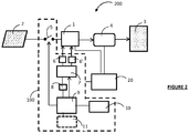
- the battery 1 is for example a lithium-ion battery. In the particular embodiment described here, it is supplied with electrical energy by a photovoltaic module 2. As an illustrative example of application, the battery 1 can equip a plant 200 of the "solar shutter" type which recovers the solar energy thanks to the photovoltaic module 2 placed for example on the shutter box.
- the invention could be applied to any other movable closure element, occultation, sun protection or screen, instead of the shutter.
- the battery 1 has the role of electrically powering the engine. In addition, here it also serves to supply the various electrical elements of the installation 200, including the control device 100 and the control unit 20.
- the installation 200 is thus energy-independent.
- the electrical energy produced by the photovoltaic module 2 from the recovered solar energy makes it possible to charge the battery 1 with the aid of an electric charge current which is variable (that is to say which varies in the time).
- the battery is charged by the photovoltaic module 2 by the implementation of a charging method, described below, for charging the battery 1 to a predefined SOC0 target charge state in a simple manner and economic, without significant resources of calculations and memories.
- the control unit 20 of the installation 200 is connected to the various elements of the installation and intended to control the operation of these elements. It includes a microprocessor. Its role is notably to control the operation of the motor 4 for driving the shutter 3 and the device 100 for controlling the charge of the battery 1.
- control module 9 is here connected to the central control unit 20.
- control module 20 is a software module comprising software instructions intended to be executed by the central processing unit. control 20 to control the charging of the battery according to the method of the invention.
- control device 100 could comprise a processing unit, such as a microprocessor, distinct from the control unit 20.
- control module 9 The function of the control module 9 is to control the operation of the controllable connection / disconnection element 5, the voltage measurement sensor 6 and the test module 7 so as to implement the method of charging the battery 1 of the invention.
- the control device 100 may also comprise a user interface 10 comprising software and hardware means for entering and retrieving information.
- a user interface 10 comprising software and hardware means for entering and retrieving information.
- charging instructions for example a manual charge instruction or a charge programming instruction
- other data useful for charging the battery for example a target charge state of the charge.
- charging instructions and data are here stored in the storage memory 8.
- the assembly comprising the driving motor 4, the battery 1, the device 100 for controlling the charge of the battery 1 and the control unit 20 form a system for controlling the shutter 3.
- the method of charging the battery 1 comprises a preliminary CONFIG configuration step in which correlation data between the state of charge or SOC of the battery 1 and the open circuit voltage VOC of the battery 1 are determined.
- This configuration step can be done in the factory or in laboratory, prior to the installation of the battery 1 on site. It can be performed on the battery 1 itself or on a reference battery identical to the battery 1.
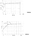
- the correlation data between state of charge SOC and open circuit voltage VOC of battery 1 can be represented by correlation curves.
- two correlation curves C1, C2 are shown for two different battery temperatures, respectively 25 ° C and 10 ° C. It emerges from this Figure 1A that the correlation between the open circuit voltage VOC of the battery 1 and its state of charge SOC does not depend on the temperature over a wide useful range of SOC, here between 10% and 85%.
- the correlation between the open circuit voltage VOC of the battery 1 and its state of charge SOC does not depend either on the state of health or SOH (of the "State Of Health") of the battery, as is apparent of the Figure 1B on which there are shown two correlation curves between the open circuit voltage VOC of the battery 1 and its state of charge SOC, denoted C3 and C4, corresponding to two SOH of the battery respectively equal to 76% and 100%.
- a particular method consists in initially charging the battery 1, preferably to a state of charge of 100%. Once the battery is charged, it is discharged gradually by a succession of discharging operations, spaced by pauses during which the battery is not connected and at rest (without discharge or charge), and the battery voltage decreases and stabilizes due to a relaxation phenomenon within the battery. During each discharge operation, the amount of electric charge delivered by the battery, for example by a coulometric counting method, is measured in order to evaluate the SOC of the battery at the end of the discharge operation.
- the relaxation periods of the battery must be of sufficient duration to reach a complete or almost complete relaxation of the battery and thus obtain a stabilization of the open circuit voltage of the battery.
- each pause between two successive discharge operations has a duration of about 2 hours.
- the duration of breaks may be shorter or longer, depending on the type of battery.
- the open circuit voltage VOC of the battery is measured using a voltage measurement sensor.
- a set of pairs of associated or corresponding SOC and VOC voltage values of the battery is thus obtained.
- the correlation data between the state of charge SOC and the open circuit voltage VOC of the battery 1 could be provided by the manufacturer of the battery.
- the correlation data between the state of charge SOC and the open circuit voltage VOC of the battery 1 can be recorded in a memory of the control device 100, here in the memory 8.
- a memory of the control device 100 here in the memory 8.
- only the open circuit voltage V0 associated with the target state of charge SOC0 is stored in the memory 8.
- the charging method enables the battery 1 to be charged to a predefined target charge state. It is implemented by the load control device 100, under the control of the control module 9.
- the target charge state SOC0 is equal to 70%. It is associated with the target open circuit voltage V0 in the correlation data. It is assumed that initially, before the charging method is implemented, the state of charge of the battery 1 is strictly lower than the target charge state SOC0.
- the control module 9 triggers the start of the charging process.
- the load can be programmed to be triggered automatically at one hour fixed, for example once a day, at a scheduled time. In a first variant, it could be triggered on detecting a state of charge of the battery 1 lower than a fixed minimum charge state. In a second variant, the load is triggered manually, on a user's specific command by means of the user interface 10.
- the method then comprises a step E1 of testing or checking the state of the battery 1 (which may be in a state of charge, rest or discharge) to verify that the battery 1 is not discharged.
- the battery 1 is discharged when it electrically feeds the drive motor 3 of the flap for winding or unrolling.
- Ibatt the current entering the battery 1. It is measured by the sensor 6 '.
- the verification E1 consists in checking whether the current Ibatt is zero (battery at rest) or greater than zero (battery in charge).
- the test E1 is executed by the test module E7, on command of the control module 9.
- step E2 of charging the battery 1.
- the battery 1 is connected to the power source 2, in The photovoltaic module, by closing the switch 5.
- the source 2 provides the battery 1 a load current Ibatt greater than zero. This charging current varies over time, depending on the solar energy recovered by the photovoltaic module 2.
- the voltage measurement sensor 6 measures the voltage Vbatt across the terminals of the battery 1 in charge, during a measurement step E3.
- first voltage is the voltage of the battery 1 measured during charging, the battery being under load current.
- the test module 7 performs a first test E4 intended to detect when the measured voltage Vbatt is equal to or substantially equal to a predetermined target voltage V0, stored in the memory 8.
- This target voltage V0 is equal to the open circuit voltage VOC of the battery 1 when the state of charge of the battery 1 is equal to the target charging state SOC0 (here 70%).
- the target voltage V0 corresponds to the voltage associated with the SOC0 target charge state, here by 70%, in the previously determined correlation data.
- the step E3 for measuring the voltage Vbatt is adapted to enable detection when the voltage Vbatt of the battery under load reaches the target voltage V0.
- the measurement step E3 comprises a succession of measurements made with a sufficiently high sampling frequency, advantageously greater than or equal to one sample per minute.
- a pause step E5 is initiated.
- the charge of the battery 1 is paused, momentarily interrupted.
- the battery 1 is disconnected from the power source 2, by opening the switch 5, in order to interrupt the charge and remains at rest (that is to say, neither charging, neither in landfill).
- the battery 1 is then in the relaxation phase, which has the effect of lowering its voltage Vbatt.
- the pause E5 has a predefined period of time, for example equal to five minutes.
- This period of time is adapted so that the voltage of the battery 1 at the end of the break is close to the voltage final battery after complete relaxation.
- close is meant to mean that the difference between the voltage of the battery at the end of the pause and the final voltage after complete relaxation is less than or equal to 10% of this final voltage.
- the duration of the pause may vary. It is generally greater than or equal to three minutes, advantageously greater than or equal to five minutes.
- the maximum pause time can advantageously be 20 minutes, preferably 15 minutes and still preferably 10 minutes. This limits the overall duration of the charging process. However, the pause time may be greater than the maximum values indicated.
- the voltage of the battery Vbatt is measured by the sensor 6, during a measurement step E6, under the control of the control module 9.
- the method then comprises a second test step E7 consisting in checking whether the voltage of the battery Vbatt measured after the pause E5, in other words of the relaxed battery, satisfies a criterion of end of charge relative to the target voltage V0.
- the end of charge criterion is that the difference between the target voltage V0 and the measured voltage Vbatt after the pause E5 must be less than or equal to a predefined limit deviation ⁇ . In other words, the end of charge criterion is satisfied (positive test E7), if the difference between the target voltage V0 and the second measured voltage Vbatt is less than or equal to the limit difference ⁇ .
- the limit difference ⁇ is preferably less than or equal to 10% of the target voltage V0, advantageously still less than or equal to 5%.
- step E8 of stopping the charge under control of the control module 9.
- the charging process returns to the state test step E1, under the control of the control module 9, the state test E1 being followed , if it is positive, by the following steps E2 to E7 previously described.
- the steps E1 to E7 are thus repeated until the end of charge criterion (difference between the target voltage V0 and the second measured voltage Vbatt2 less than or equal to the limit difference ⁇ ) is satisfied.
- the evolution of the voltage Vbatt of the battery 1 during the charge process just described, according to an example of implementation, is represented in a simplified manner.
- the figure 4 represents the charge profile of the battery 1 during the implementation of the charging method of the invention according to the first embodiment described.
- the voltage Vbatt of the battery 1 increases continuously until reaching the target voltage V0.
- the voltage Vbatt of the battery 1 oscillates, by the implementation of a succession of alternating charges and pauses, as follows: at each oscillation , the voltage increases to the target voltage V0, during a charging operation E2, then decreases slightly, during a break E5.
- the voltage decreased after each break E5 is gradually approaching the target voltage V0.
- the charge is stopped when the voltage of the battery decreased after a pause is close to the target voltage V0, the difference between these two voltages being less than ⁇ .
- the charging method makes it possible to charge the battery 1 to a target charge state SOC0 equal to 70%. It is assumed that initially, before the charging method is implemented, the state of charge of the battery is strictly lower than the target charging state SOC0.
- control device 100 integrates a time counter 11.
- Step E10 the control device 100 controls the start of the charging process.
- Step E10 is analogous to step E0 previously described.
- the method then comprises a step E12 for testing or checking the state of the battery 1, which battery can be in charge, at rest or in discharge, in order to verify that the battery 1 is not being discharged.
- the E12 test consists of checking whether the current entering the battery 1, Ibatt, is zero (battery at rest) or greater than zero (battery in charge).
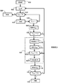
- step E20 If the state test E12 is negative (branch N on the figure 5 ), the battery 1 being discharged, the charging process is immediately stopped (step E20).
- step E13 of charging the battery 1.
- the switch 5 under the control of the control module 9, the switch 5 is closed and the battery 1 is connected to the power source 2 (here the photovoltaic module) which delivers a charge current Ibatt strictly greater than zero.
- This charging current Ibatt battery 1 varies over time, depending on the solar energy recovered by the photovoltaic module 2.
- a test step E14 is performed on the charging time in order to check whether the charging time tch has reached a fixed duration ⁇ .
- This duration ⁇ corresponds to the duration of a period or a time interval separating two Successive measurements of the battery voltage 1.
- the duration ⁇ is of the order of a few minutes, in this case of 5 minutes.
- the test E14 consists of checking if tch ⁇ ⁇ .
- test E14 If the test E14 is positive, in other words as soon as the charging time tch is equal to or greater than the duration ⁇ of the measurement period, the control module 9 triggers a measurement of the voltage Vbatt of the battery in charge by the sensor 6, during a first measurement step E15.
- the first step E15 for measuring the voltage Vbatt of the battery 1 under load makes spaced measurements, separated by a fixed time interval, predefined ⁇ .
- This time interval is advantageously greater than or equal to 1 minute, advantageously still greater than or equal to 3 minutes, preferably greater than or equal to 5 minutes. Because of this, the number of measurements of the voltage Vbatt is limited.
- the measurement step E15 is followed by a first test step on the voltage E16.
- the test E16 aims to detect when the voltage Vbatt of the battery measured during step E15 exceeds for the first time the target voltage V0 preset. As a reminder, the target voltage V0 is equal to the open circuit voltage VOC of the battery 1 when the state of charge of the battery 1 is equal to the target charge state (here 70%).
- the control module 9 triggers a break step E17 (branch Y on the figure 5 ).
- pause E17 the charge of the battery 1 is momentarily interrupted.
- the battery 1 is disconnected from the power source 2, here by opening the switch 5, under the control of the control module 9.
- the battery 1 is at rest (it is ie neither in charge nor in discharge). The battery 1 is then in the relaxation phase, which has the effect of lowering the voltage Vbatt.
- the pause E17 has a total predefined duration, for example equal to five minutes.
- This total pause time is adapted so that the voltage of the battery 1 at the end of the pause period is close to the final theoretical voltage of the battery after a complete relaxation requiring a pause of several hours, ie the voltage that the battery would reach theoretically if it was totally relaxed.
- close is meant to mean that the difference between the voltage of the battery at the end of the pause and the final voltage after complete relaxation is less than or equal to 10% of this final voltage.
- the duration of the pause may vary. It is generally greater than or equal to three minutes, advantageously greater than or equal to five minutes.
- the maximum pause time can advantageously be 20 minutes, preferably 15 minutes and still preferably 10 minutes. This limits the overall duration of the charging process.
- the pause time may be greater than the maximum values indicated.
- the pause step E17 is split into two successive pauses E170, E173.
- the first break E170 is short-lived. Its duration d1 is less than the duration d2 of the second break E173.
- the duration d1 of the first pause step is one minute and the duration d2 of the second break E173 is four minutes.
- the duration d1 of the first pause is advantageously less than or equal to 2 minutes, advantageously still less than or equal to 1 minute.
- the sum of the respective durations d1 and d2 of the two pauses E170 and E173 is equal to the fixed pause time.
- the voltage of the battery Vbatt is measured in a step E171 by the sensor 6. Then the test module 7 performs an intermediate test step E172 to verify whether the measured voltage Vbatt is always greater than or equal to the target voltage V0.
- the control device 100 implements the second pause step E173 of a duration d2.
- the second pause E173 is performed only if the intermediate test is positive, ie only if the voltage Vbatt after the first pause is always greater than the target voltage V0.
- This alternative embodiment reduces the total time of pause during charging to maximize the solar energy during charging.
- the voltage of the battery Vbatt is measured by the sensor 6, during a measurement step E18.
- step E17 could comprise only one pause of duration of pause.
- the method then comprises a test step E19 consisting in checking whether the voltage Vbatt measured during the step E18, in other words the battery voltage after the pause E17, satisfies a criterion of end of charge.
- This step is implemented by the test module 7, under the control of the control module 9.
- the end of charge criterion is that the voltage Vbatt of the battery 1 measured after the pause E17, and therefore after relaxation, must be greater than or equal to the target voltage V0. In other words, the end of charge criterion is satisfied (test E19 positive) if the voltage Vbatt of the battery 1 after the pause E17 is greater than or equal to the target voltage V0.
- test E19 is positive (branch Y on the figure 5 ), ie if the voltage Vbatt of the battery 1 after the pause E17 is greater than or equal to the target voltage V0, the charging process is stopped (step E20 of stopping the charge).
- the steps E12 and following are then repeated.
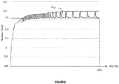
- the figure 6 represents the charge profile of the battery 1 during the implementation of the charging method of the invention according to the second embodiment.
- the voltage Vbatt of the battery 1 increases continuously until slightly exceed the target voltage V0.
- the voltage Vbatt of the battery 1 oscillates around the target voltage V0, by a succession of charging operations separated by pauses.
- the voltage Vbatt increases and exceeds the target voltage V0, during each charging operation, then decreases during each pause by going back below the target voltage V0.
- the charge is stopped as soon as the voltage of the battery decreased after a pause remains higher than the target voltage V0.
- the target state of charge is 70%.
- the target state of charge of the battery could be between 30% and 85%, advantageously still between 50% and 80%, advantageously still between 65% and 75%.
- the invention can be applied to any type of power source. It finds an interesting application for a variable current power source but could also apply to a fixed current power source.
- the power source is not limited to a photovoltaic module. It could use any other renewable energy source and be adapted to generate a charging electric current from this renewable energy source.
- the battery 1 is intended to charge the drive motor 4 with a mobile closure, concealment, sun protection or screen element.
- the invention could be applied to any other element to supply electrical energy using the battery 1, for example a parking meter, a street lamp or other street furniture, or even a door or window motor.
- the invention therefore also relates to a system comprising an element for supplying electrical energy, a battery of electrochemical accumulators, in particular a lithium battery, intended to be charged by connection to an external power source and to supply electrical energy to this element. , and a device for controlling the charge of the battery as previously described.
- the present invention can be applied to any type of battery, especially Lithium batteries such as Lithium-Ion batteries, but also lead batteries, NiMH.
Landscapes
- Engineering & Computer Science (AREA)
- Manufacturing & Machinery (AREA)
- Chemical & Material Sciences (AREA)
- Chemical Kinetics & Catalysis (AREA)
- Electrochemistry (AREA)
- General Chemical & Material Sciences (AREA)
- Power Engineering (AREA)
- Life Sciences & Earth Sciences (AREA)
- Sustainable Development (AREA)
- Sustainable Energy (AREA)
- Secondary Cells (AREA)
- Charge And Discharge Circuits For Batteries Or The Like (AREA)
Claims (15)
- Verfahren zum Laden einer Batterie von elektrochemischen Akkumulatoren (1), insbesondere einer Lithiumbatterie, mittels einer Leistungsquelle (2) welches Folgendes aufweist:einen Schritt (E13) des Ladens der Batterie (1) durch Verbindung mit der Leistungsquelle (2) für ein bestimmtes Zeitintervall, welches eine Dauer von größer oder gleich 1 Minute hat;am Ende des Zeitintervalls, einen ersten Schritt (E15) des Messens einer Spannung (Vbatt) der Batterie (1) im Lademodus;einen ersten Test (E16), der es ermöglicht zu detektieren, ob die gemessene Spannung (Vbatt) der Batterie (1) im Lademodus während des ersten Messungsschrittes gleich oder größer einer Zielspannung (V0) ist, die gleich einer Spannung bei offener Schaltung der Batterie in einem erwünschen Zielzustand der Ladung (SOCO) ist;wenn der erste Test negativ ist, erneutes Aufnehmen des Ladevorgangs vom Ladeschritt (E13);wenn der erste Test positiv ist, einen Pausenschritt (E17), von vordefinierter Dauer (dpause), während dem die Batterie (1) von der Leistungsquelle (2) getrennt und im Leerlaufzustand ist;einen zweiten Schritt (E18) des Messens der Spannung (Vbatt) der Batterie (1) am Ende der Pause;einen zweiten Test (E19), der aufweist, zu überprüfen, ob die Spannung (Vbatt) der Batterie (1), die am Ende der Pause gemessen wird, ein Ladungsendekriterium relativ zur Zielspannung erfüllt;wenn der zweite Test (E19) positiv ist, Stoppen des Ladevorgangs (E20); undwenn der zweite Test (E7; E19) negativ ist, erneutes Aufnehmen des Ladevorgangs vom Ladeschritt (E13),wobei der Pausenschritt Folgendes aufweist:eine erste Pause (E170), gefolgt durch einen Schritt (E171) des Messens der Batteriespannung (Vbatt) und durch einen Zwischentestschritt (E172), um zu überprüfen, ob die Spannung, die nach der ersten Pause gemessen wird, größer oder gleich der Zielspannung ist, undeine zweite Pause (E173), die nur eingerichtet wird, wenn der Zwischentest positiv ist,und wobei, die Dauer der ersten Pause kürzer als die Dauer der zweite Pause ist.
- Verfahren nach Anspruch 1, wobei, wenn der Zwischenschritt (E172) negativ ist, der Ladeschritt (E13) direkt nach der ersten Pause (E170) wiederholt wird.
- Verfahren nach Anspruch 1 oder 2, wobei die Dauer der ersten Pause (E170) kleiner oder gleich 2 Minuten ist, vorteilhafterweise kleiner oder gleich 1 Minute.
- Verfahren nach einem der Ansprüche 1 bis 3, wobei der Zielzustand der Ladung der Batterie, im Bereich von 30% bis 85% ist, vorteilhafterweise von 50% bis 80%, insbesondere vorteilhafterweise von 65% bis 75%.
- Verfahren nach einem der Ansprüche 1 bis 4, welches weiter einen Vorkonfigurationsschritt aufweist, während dem Daten einer Korrelation zwischen dem Zustand der Ladung der Batterie und der Spannung bei offener Schaltung der Batterie bestimmt werden.
- Ladeverfahren nach einem der Ansprüche 1 bis 5, wobei die Leistungsquelle (2) ausgebildet ist, um einen variablen Strom zu liefern.
- Verfahren nach Anspruch 6, wobei die Leistungsquelle (2) ausgebildet ist, um einen elektrischen Ladestrom von einer erneuerbaren Energiequelle zu erzeugen.
- Verfahren nach Anspruch 7, wobei die Leistungsquelle (2) eine Photovoltaikeinheit aufweist.
- Verfahren nach einem der Ansprüche 1 bis 8, wobei die Dauer (dpause) des Pausenschrittes (E17) größer als 3 Minuten ist, vorteilhafterweise gleich oder größer als 5 Minuten.
- Verfahren nach einem der Ansprüche 1 bis 9, wobei die Dauer (dpause) des Pausenschrittes (E17) kleiner oder gleich 20 Minuten ist, vorzugsweise kleiner oder gleich 15 Minuten und insbesondere vorteilhafterweise kleiner oder gleich 10 Minuten.
- Vorrichtung (100) zum Treiben der Ladung einer Batterie von elektrochemischen Akkumulatoren (1), insbesondere einer Lithiumbatterie, mittels einer Leistungsquelle (2), die vorgesehen ist, um die Batterie auf einen vordefinierten Zielladungszustand zu laden, welche Folgendes aufweist:ein antreibbares Element (5) zur Verbindung und Trennung der Batterie mit bzw. von der Leistungsquelle (2);einen Sensor (6) zur Messung der Spannung der Batterie (1);eine Einheit (7) zum Testen der gemessenen Spannung, die mit einem Speicher zum Speichern einer Zielspannung gekoppelt ist, die gleich der Spannung bei offenem Schaltkreis der Batterie (1) auf einem erwünschen Zielladungszustand ist;eine Steuereinheit (9), die vorgesehen ist, um das antreibbare Verbindungs- und Trennungselement, den Spannungsmessungssensor und die Testeinheit zu steuern, wobei die Steuereinheit konfiguriert ist, um das Verfahren nach einem der Ansprüche 1 bis 10 auszuführen.
- System, welches ein Element aufweist, welches mit elektrischer Energie versorgt werden soll, weiter eine Batterie von elektrochemischen Akkumulatoren, insbesondere eine Lithiumbatterie, die vorgesehen ist, um durch Verbindung mit einer externen Leistungsquelle geladen zu werden und das Element mit elektrischer Energie zu versorgen, und die Batterieladevorrichtung nach Anspruch 11.
- System nach Anspruch 12, wobei das mit elektrischer Energie zu versorgende Element ein Antriebsmotor eines bewegbaren Schließ-, Beschattungs-, Sonnenschutz- oder Abschirmungselementes ist.
- Baugruppe, die ein mobiles Schließ-, Abschattungs-, Sonnenschutz- oder Abschirmungselement und das System nach Anspruch 13 aufweist.
- Baugruppe nach Anspruch 14, die eine Leistungsquelle aufweist, die ausgebildet ist, um einen elektrischen Ladestrom von einer Quelle für erneuerbare Energie zu erzeugen, insbesondere eine Photovoltaikeinheit.
Priority Applications (1)
| Application Number | Priority Date | Filing Date | Title |
|---|---|---|---|
| PL17161451T PL3220471T3 (pl) | 2016-03-18 | 2017-03-16 | Sposób ładowania baterii z akumulatorami elektrochemicznymi i urządzenie sterujące ładowaniem |
Applications Claiming Priority (1)
| Application Number | Priority Date | Filing Date | Title |
|---|---|---|---|
| FR1652325A FR3049115A1 (fr) | 2016-03-18 | 2016-03-18 | Procede de charge d'une batterie d'accumulateurs electrochimiques et dispositif de pilotage de la charge |
Publications (2)
| Publication Number | Publication Date |
|---|---|
| EP3220471A1 EP3220471A1 (de) | 2017-09-20 |
| EP3220471B1 true EP3220471B1 (de) | 2018-10-31 |
Family
ID=55808750
Family Applications (1)
| Application Number | Title | Priority Date | Filing Date |
|---|---|---|---|
| EP17161451.4A Active EP3220471B1 (de) | 2016-03-18 | 2017-03-16 | Verfahren zum laden einer batterie von elektrochemischen akkumulatoren und vorrichtung zur kontrolle des ladevorgangs |
Country Status (4)
| Country | Link |
|---|---|
| EP (1) | EP3220471B1 (de) |
| ES (1) | ES2708681T3 (de) |
| FR (1) | FR3049115A1 (de) |
| PL (1) | PL3220471T3 (de) |
Families Citing this family (4)
| Publication number | Priority date | Publication date | Assignee | Title |
|---|---|---|---|---|
| CN112378177B (zh) * | 2020-10-20 | 2022-05-13 | 常州百利锂电智慧工厂有限公司 | 一种适用于锂电三元材料的加工系统及加工工艺 |
| FR3118500B1 (fr) | 2020-12-30 | 2022-12-30 | Somfy Activites Sa | Procédé de commande en fonctionnement d’un dispositf d’entrainement motorisé et dispositif d’entrainement motorisé mettant en œuvre un tel procédé |
| FR3158802B1 (fr) | 2024-01-29 | 2026-02-06 | Bhg | Procédé d’auto-paramétrage des conditions de charge d'une batterie d'accumulateurs |
| CN120610162B (zh) * | 2025-08-12 | 2025-10-17 | 辽宁九夷锂能股份有限公司 | 一种锂电池盖帽ptc性能测试方法 |
Family Cites Families (4)
| Publication number | Priority date | Publication date | Assignee | Title |
|---|---|---|---|---|
| JPH1010212A (ja) * | 1996-06-24 | 1998-01-16 | Sony Corp | 電池評価方法及び電池評価装置 |
| DE19913627A1 (de) * | 1999-03-25 | 2000-10-26 | Siemens Ag | Verfahren und Vorrichtung zum Laden eines Akkumulators sowie Verfahren zum Überprüfen des Ladezustands eines Akkumulators |
| FR2952235B1 (fr) | 2009-10-29 | 2015-01-16 | Commissariat Energie Atomique | Procede de charge ou de decharge d'une batterie pour determiner la fin de charge ou de decharge en fonction de mesures de courant et de temperature |
| FR2992142B1 (fr) * | 2012-06-13 | 2014-07-11 | Somfy Sas | Element de support d’une batterie dans un tube d’enroulement d’un ecran domotique. |
-
2016
- 2016-03-18 FR FR1652325A patent/FR3049115A1/fr not_active Withdrawn
-
2017
- 2017-03-16 EP EP17161451.4A patent/EP3220471B1/de active Active
- 2017-03-16 ES ES17161451T patent/ES2708681T3/es active Active
- 2017-03-16 PL PL17161451T patent/PL3220471T3/pl unknown
Non-Patent Citations (1)
| Title |
|---|
| None * |
Also Published As
| Publication number | Publication date |
|---|---|
| FR3049115A1 (fr) | 2017-09-22 |
| EP3220471A1 (de) | 2017-09-20 |
| ES2708681T3 (es) | 2019-04-10 |
| PL3220471T3 (pl) | 2019-04-30 |
Similar Documents
| Publication | Publication Date | Title |
|---|---|---|
| EP2087574B1 (de) | Verfahren zur ladungsverwaltung einer wiederaufladbaren batterie | |
| CA2594826C (fr) | Procede de chargement equilibre d'une batterie lithium-ion ou lithium polymere | |
| EP1685622B1 (de) | Gleichgewichts-ladeverfahren für eine lithiumionen- oder lithiumpolymerbatterie | |
| EP1774353B1 (de) | Verfahren zur akkuspeicherverwaltung | |
| EP2707935B1 (de) | Verfahren zur batterieverwaltung und diagnose | |
| EP3220471B1 (de) | Verfahren zum laden einer batterie von elektrochemischen akkumulatoren und vorrichtung zur kontrolle des ladevorgangs | |
| EP0626746B1 (de) | Ladekontrollverfahren und Ladegerät für eine gasdichten Nickel-Akkumulator | |
| EP2873133B1 (de) | Verfahren zur ladung einer batterie und entsprechende batterie | |
| EP1990890A1 (de) | Aufladeverfahren einer Batterie eines autonomen Systems | |
| FR2860301A1 (fr) | Appareil de surveillance de l'etat d'une batterie d'automobile | |
| EP0498715B1 (de) | Verfahren zur Ladungsoptimierung einer Akkumulatorenbatterie und Vorrichtung zu dessen Durchführung | |
| WO2008081106A1 (fr) | Procede de determination du seuil de fin de decharge d'une batterie rechargeable | |
| WO2017050944A1 (fr) | Procede et dispositif de determination d'un indicateur d'etat de sante d'une batterie lithium | |
| EP3667345A1 (de) | Verfahren zur bestimmung des gesundheitszustands der zellen einer batterie | |
| EP2945817A1 (de) | Verwaltung der ladung einer batterie | |
| WO2008046980A2 (fr) | Procédé de gestion de la fin de décharge d'une batterie rechargeable | |
| EP0980130B1 (de) | Schnellladesteuerungsverfahren für einen industriellen Akkumulator mit alkalischem Elektrolyt | |
| EP3999863B1 (de) | Schätzung des soc eines elektrochemischen elements | |
| EP3235048B1 (de) | Gepulstes ladeverfahren für lithium-ionen batterien und apparat dafür | |
| FR2974248A1 (fr) | Procede de charge optimal d'un accumulateur electrochimique | |
| EP4400855B1 (de) | Verfahren und vorrichtung zur bestimmung eines ladezustandes einer batterie zur energieversorgung einer verdunkelungsvorrichtung für fenster oder eines sonnenschutzteils | |
| FR2722336A1 (fr) | Procede pour maintenir la charge d'un accumulateur et surveiller sa capacite residuelle, son etat de charge et son vieillissement | |
| WO2004081585A2 (fr) | Procede et installation de surveillance de l'etat et de gestion d'une batterie au plomb |
Legal Events
| Date | Code | Title | Description |
|---|---|---|---|
| PUAI | Public reference made under article 153(3) epc to a published international application that has entered the european phase |
Free format text: ORIGINAL CODE: 0009012 |
|
| STAA | Information on the status of an ep patent application or granted ep patent |
Free format text: STATUS: THE APPLICATION HAS BEEN PUBLISHED |
|
| AK | Designated contracting states |
Kind code of ref document: A1 Designated state(s): AL AT BE BG CH CY CZ DE DK EE ES FI FR GB GR HR HU IE IS IT LI LT LU LV MC MK MT NL NO PL PT RO RS SE SI SK SM TR |
|
| AX | Request for extension of the european patent |
Extension state: BA ME |
|
| STAA | Information on the status of an ep patent application or granted ep patent |
Free format text: STATUS: REQUEST FOR EXAMINATION WAS MADE |
|
| 17P | Request for examination filed |
Effective date: 20171003 |
|
| RBV | Designated contracting states (corrected) |
Designated state(s): AL AT BE BG CH CY CZ DE DK EE ES FI FR GB GR HR HU IE IS IT LI LT LU LV MC MK MT NL NO PL PT RO RS SE SI SK SM TR |
|
| RIC1 | Information provided on ipc code assigned before grant |
Ipc: H02J 7/00 20060101ALI20180312BHEP Ipc: H01M 10/44 20060101AFI20180312BHEP Ipc: H01M 10/0525 20100101ALN20180312BHEP Ipc: H01M 10/48 20060101ALI20180312BHEP Ipc: E06B 9/68 20060101ALI20180312BHEP Ipc: H01M 10/46 20060101ALI20180312BHEP Ipc: H02J 7/35 20060101ALI20180312BHEP |
|
| GRAP | Despatch of communication of intention to grant a patent |
Free format text: ORIGINAL CODE: EPIDOSNIGR1 |
|
| RIC1 | Information provided on ipc code assigned before grant |
Ipc: H01M 10/46 20060101ALI20180321BHEP Ipc: H01M 10/0525 20100101ALN20180321BHEP Ipc: H01M 10/44 20060101AFI20180321BHEP Ipc: H02J 7/35 20060101ALI20180321BHEP Ipc: E06B 9/68 20060101ALI20180321BHEP Ipc: H02J 7/00 20060101ALI20180321BHEP Ipc: H01M 10/48 20060101ALI20180321BHEP |
|
| STAA | Information on the status of an ep patent application or granted ep patent |
Free format text: STATUS: GRANT OF PATENT IS INTENDED |
|
| INTG | Intention to grant announced |
Effective date: 20180426 |
|
| GRAS | Grant fee paid |
Free format text: ORIGINAL CODE: EPIDOSNIGR3 |
|
| GRAA | (expected) grant |
Free format text: ORIGINAL CODE: 0009210 |
|
| STAA | Information on the status of an ep patent application or granted ep patent |
Free format text: STATUS: THE PATENT HAS BEEN GRANTED |
|
| AK | Designated contracting states |
Kind code of ref document: B1 Designated state(s): AL AT BE BG CH CY CZ DE DK EE ES FI FR GB GR HR HU IE IS IT LI LT LU LV MC MK MT NL NO PL PT RO RS SE SI SK SM TR |
|
| REG | Reference to a national code |
Ref country code: CH Ref legal event code: EP Ref country code: GB Ref legal event code: FG4D Free format text: NOT ENGLISH |
|
| REG | Reference to a national code |
Ref country code: AT Ref legal event code: REF Ref document number: 1060507 Country of ref document: AT Kind code of ref document: T Effective date: 20181115 |
|
| REG | Reference to a national code |
Ref country code: DE Ref legal event code: R096 Ref document number: 602017000739 Country of ref document: DE |
|
| REG | Reference to a national code |
Ref country code: IE Ref legal event code: FG4D Free format text: LANGUAGE OF EP DOCUMENT: FRENCH |
|
| REG | Reference to a national code |
Ref country code: NL Ref legal event code: MP Effective date: 20181031 |
|
| REG | Reference to a national code |
Ref country code: LT Ref legal event code: MG4D |
|
| REG | Reference to a national code |
Ref country code: ES Ref legal event code: FG2A Ref document number: 2708681 Country of ref document: ES Kind code of ref document: T3 Effective date: 20190410 |
|
| REG | Reference to a national code |
Ref country code: AT Ref legal event code: MK05 Ref document number: 1060507 Country of ref document: AT Kind code of ref document: T Effective date: 20181031 |
|
| PG25 | Lapsed in a contracting state [announced via postgrant information from national office to epo] |
Ref country code: LV Free format text: LAPSE BECAUSE OF FAILURE TO SUBMIT A TRANSLATION OF THE DESCRIPTION OR TO PAY THE FEE WITHIN THE PRESCRIBED TIME-LIMIT Effective date: 20181031 Ref country code: HR Free format text: LAPSE BECAUSE OF FAILURE TO SUBMIT A TRANSLATION OF THE DESCRIPTION OR TO PAY THE FEE WITHIN THE PRESCRIBED TIME-LIMIT Effective date: 20181031 Ref country code: NO Free format text: LAPSE BECAUSE OF FAILURE TO SUBMIT A TRANSLATION OF THE DESCRIPTION OR TO PAY THE FEE WITHIN THE PRESCRIBED TIME-LIMIT Effective date: 20190131 Ref country code: BG Free format text: LAPSE BECAUSE OF FAILURE TO SUBMIT A TRANSLATION OF THE DESCRIPTION OR TO PAY THE FEE WITHIN THE PRESCRIBED TIME-LIMIT Effective date: 20190131 Ref country code: FI Free format text: LAPSE BECAUSE OF FAILURE TO SUBMIT A TRANSLATION OF THE DESCRIPTION OR TO PAY THE FEE WITHIN THE PRESCRIBED TIME-LIMIT Effective date: 20181031 Ref country code: LT Free format text: LAPSE BECAUSE OF FAILURE TO SUBMIT A TRANSLATION OF THE DESCRIPTION OR TO PAY THE FEE WITHIN THE PRESCRIBED TIME-LIMIT Effective date: 20181031 Ref country code: AT Free format text: LAPSE BECAUSE OF FAILURE TO SUBMIT A TRANSLATION OF THE DESCRIPTION OR TO PAY THE FEE WITHIN THE PRESCRIBED TIME-LIMIT Effective date: 20181031 Ref country code: IS Free format text: LAPSE BECAUSE OF FAILURE TO SUBMIT A TRANSLATION OF THE DESCRIPTION OR TO PAY THE FEE WITHIN THE PRESCRIBED TIME-LIMIT Effective date: 20190228 |
|
| PG25 | Lapsed in a contracting state [announced via postgrant information from national office to epo] |
Ref country code: NL Free format text: LAPSE BECAUSE OF FAILURE TO SUBMIT A TRANSLATION OF THE DESCRIPTION OR TO PAY THE FEE WITHIN THE PRESCRIBED TIME-LIMIT Effective date: 20181031 Ref country code: GR Free format text: LAPSE BECAUSE OF FAILURE TO SUBMIT A TRANSLATION OF THE DESCRIPTION OR TO PAY THE FEE WITHIN THE PRESCRIBED TIME-LIMIT Effective date: 20190201 Ref country code: SE Free format text: LAPSE BECAUSE OF FAILURE TO SUBMIT A TRANSLATION OF THE DESCRIPTION OR TO PAY THE FEE WITHIN THE PRESCRIBED TIME-LIMIT Effective date: 20181031 Ref country code: RS Free format text: LAPSE BECAUSE OF FAILURE TO SUBMIT A TRANSLATION OF THE DESCRIPTION OR TO PAY THE FEE WITHIN THE PRESCRIBED TIME-LIMIT Effective date: 20181031 Ref country code: PT Free format text: LAPSE BECAUSE OF FAILURE TO SUBMIT A TRANSLATION OF THE DESCRIPTION OR TO PAY THE FEE WITHIN THE PRESCRIBED TIME-LIMIT Effective date: 20190301 Ref country code: AL Free format text: LAPSE BECAUSE OF FAILURE TO SUBMIT A TRANSLATION OF THE DESCRIPTION OR TO PAY THE FEE WITHIN THE PRESCRIBED TIME-LIMIT Effective date: 20181031 |
|
| PG25 | Lapsed in a contracting state [announced via postgrant information from national office to epo] |
Ref country code: CZ Free format text: LAPSE BECAUSE OF FAILURE TO SUBMIT A TRANSLATION OF THE DESCRIPTION OR TO PAY THE FEE WITHIN THE PRESCRIBED TIME-LIMIT Effective date: 20181031 Ref country code: DK Free format text: LAPSE BECAUSE OF FAILURE TO SUBMIT A TRANSLATION OF THE DESCRIPTION OR TO PAY THE FEE WITHIN THE PRESCRIBED TIME-LIMIT Effective date: 20181031 |
|
| REG | Reference to a national code |
Ref country code: DE Ref legal event code: R097 Ref document number: 602017000739 Country of ref document: DE |
|
| PG25 | Lapsed in a contracting state [announced via postgrant information from national office to epo] |
Ref country code: SK Free format text: LAPSE BECAUSE OF FAILURE TO SUBMIT A TRANSLATION OF THE DESCRIPTION OR TO PAY THE FEE WITHIN THE PRESCRIBED TIME-LIMIT Effective date: 20181031 Ref country code: EE Free format text: LAPSE BECAUSE OF FAILURE TO SUBMIT A TRANSLATION OF THE DESCRIPTION OR TO PAY THE FEE WITHIN THE PRESCRIBED TIME-LIMIT Effective date: 20181031 Ref country code: SM Free format text: LAPSE BECAUSE OF FAILURE TO SUBMIT A TRANSLATION OF THE DESCRIPTION OR TO PAY THE FEE WITHIN THE PRESCRIBED TIME-LIMIT Effective date: 20181031 Ref country code: RO Free format text: LAPSE BECAUSE OF FAILURE TO SUBMIT A TRANSLATION OF THE DESCRIPTION OR TO PAY THE FEE WITHIN THE PRESCRIBED TIME-LIMIT Effective date: 20181031 |
|
| PLBE | No opposition filed within time limit |
Free format text: ORIGINAL CODE: 0009261 |
|
| STAA | Information on the status of an ep patent application or granted ep patent |
Free format text: STATUS: NO OPPOSITION FILED WITHIN TIME LIMIT |
|
| 26N | No opposition filed |
Effective date: 20190801 |
|
| PG25 | Lapsed in a contracting state [announced via postgrant information from national office to epo] |
Ref country code: SI Free format text: LAPSE BECAUSE OF FAILURE TO SUBMIT A TRANSLATION OF THE DESCRIPTION OR TO PAY THE FEE WITHIN THE PRESCRIBED TIME-LIMIT Effective date: 20181031 Ref country code: MC Free format text: LAPSE BECAUSE OF FAILURE TO SUBMIT A TRANSLATION OF THE DESCRIPTION OR TO PAY THE FEE WITHIN THE PRESCRIBED TIME-LIMIT Effective date: 20181031 |
|
| PG25 | Lapsed in a contracting state [announced via postgrant information from national office to epo] |
Ref country code: LU Free format text: LAPSE BECAUSE OF NON-PAYMENT OF DUE FEES Effective date: 20190316 |
|
| REG | Reference to a national code |
Ref country code: BE Ref legal event code: MM Effective date: 20190331 |
|
| PG25 | Lapsed in a contracting state [announced via postgrant information from national office to epo] |
Ref country code: IE Free format text: LAPSE BECAUSE OF NON-PAYMENT OF DUE FEES Effective date: 20190316 |
|
| PG25 | Lapsed in a contracting state [announced via postgrant information from national office to epo] |
Ref country code: BE Free format text: LAPSE BECAUSE OF NON-PAYMENT OF DUE FEES Effective date: 20190331 |
|
| PG25 | Lapsed in a contracting state [announced via postgrant information from national office to epo] |
Ref country code: TR Free format text: LAPSE BECAUSE OF FAILURE TO SUBMIT A TRANSLATION OF THE DESCRIPTION OR TO PAY THE FEE WITHIN THE PRESCRIBED TIME-LIMIT Effective date: 20181031 |
|
| PG25 | Lapsed in a contracting state [announced via postgrant information from national office to epo] |
Ref country code: MT Free format text: LAPSE BECAUSE OF FAILURE TO SUBMIT A TRANSLATION OF THE DESCRIPTION OR TO PAY THE FEE WITHIN THE PRESCRIBED TIME-LIMIT Effective date: 20181031 |
|
| REG | Reference to a national code |
Ref country code: CH Ref legal event code: PL |
|
| PG25 | Lapsed in a contracting state [announced via postgrant information from national office to epo] |
Ref country code: CH Free format text: LAPSE BECAUSE OF NON-PAYMENT OF DUE FEES Effective date: 20200331 Ref country code: LI Free format text: LAPSE BECAUSE OF NON-PAYMENT OF DUE FEES Effective date: 20200331 |
|
| PG25 | Lapsed in a contracting state [announced via postgrant information from national office to epo] |
Ref country code: CY Free format text: LAPSE BECAUSE OF FAILURE TO SUBMIT A TRANSLATION OF THE DESCRIPTION OR TO PAY THE FEE WITHIN THE PRESCRIBED TIME-LIMIT Effective date: 20181031 |
|
| PG25 | Lapsed in a contracting state [announced via postgrant information from national office to epo] |
Ref country code: HU Free format text: LAPSE BECAUSE OF FAILURE TO SUBMIT A TRANSLATION OF THE DESCRIPTION OR TO PAY THE FEE WITHIN THE PRESCRIBED TIME-LIMIT; INVALID AB INITIO Effective date: 20170316 |
|
| GBPC | Gb: european patent ceased through non-payment of renewal fee |
Effective date: 20210316 |
|
| PG25 | Lapsed in a contracting state [announced via postgrant information from national office to epo] |
Ref country code: GB Free format text: LAPSE BECAUSE OF NON-PAYMENT OF DUE FEES Effective date: 20210316 |
|
| PG25 | Lapsed in a contracting state [announced via postgrant information from national office to epo] |
Ref country code: MK Free format text: LAPSE BECAUSE OF FAILURE TO SUBMIT A TRANSLATION OF THE DESCRIPTION OR TO PAY THE FEE WITHIN THE PRESCRIBED TIME-LIMIT Effective date: 20181031 |
|
| PGFP | Annual fee paid to national office [announced via postgrant information from national office to epo] |
Ref country code: PL Payment date: 20250310 Year of fee payment: 9 |
|
| PGFP | Annual fee paid to national office [announced via postgrant information from national office to epo] |
Ref country code: ES Payment date: 20250416 Year of fee payment: 9 |
|
| PGFP | Annual fee paid to national office [announced via postgrant information from national office to epo] |
Ref country code: IT Payment date: 20250331 Year of fee payment: 9 |
|
| PGFP | Annual fee paid to national office [announced via postgrant information from national office to epo] |
Ref country code: DE Payment date: 20260320 Year of fee payment: 10 |
|
| PGFP | Annual fee paid to national office [announced via postgrant information from national office to epo] |
Ref country code: FR Payment date: 20260324 Year of fee payment: 10 |