EP3220512B1 - Motor - Google Patents
Motor Download PDFInfo
- Publication number
- EP3220512B1 EP3220512B1 EP15859982.9A EP15859982A EP3220512B1 EP 3220512 B1 EP3220512 B1 EP 3220512B1 EP 15859982 A EP15859982 A EP 15859982A EP 3220512 B1 EP3220512 B1 EP 3220512B1
- Authority
- EP
- European Patent Office
- Prior art keywords
- busbar
- prevention unit
- vibration prevention
- inner circumferential
- motor
- Prior art date
- Legal status (The legal status is an assumption and is not a legal conclusion. Google has not performed a legal analysis and makes no representation as to the accuracy of the status listed.)
- Active
Links
Images


Classifications
-
- H—ELECTRICITY
- H02—GENERATION; CONVERSION OR DISTRIBUTION OF ELECTRIC POWER
- H02K—DYNAMO-ELECTRIC MACHINES
- H02K3/00—Details of windings
- H02K3/32—Windings characterised by the shape, form or construction of the insulation
- H02K3/38—Windings characterised by the shape, form or construction of the insulation around winding heads, equalising connectors, or connections thereto
-
- H—ELECTRICITY
- H02—GENERATION; CONVERSION OR DISTRIBUTION OF ELECTRIC POWER
- H02K—DYNAMO-ELECTRIC MACHINES
- H02K5/00—Casings; Enclosures; Supports
- H02K5/24—Casings; Enclosures; Supports specially adapted for suppression or reduction of noise or vibrations
-
- H—ELECTRICITY
- H02—GENERATION; CONVERSION OR DISTRIBUTION OF ELECTRIC POWER
- H02K—DYNAMO-ELECTRIC MACHINES
- H02K1/00—Details of the magnetic circuit
- H02K1/06—Details of the magnetic circuit characterised by the shape, form or construction
- H02K1/12—Stationary parts of the magnetic circuit
-
- H—ELECTRICITY
- H02—GENERATION; CONVERSION OR DISTRIBUTION OF ELECTRIC POWER
- H02K—DYNAMO-ELECTRIC MACHINES
- H02K1/00—Details of the magnetic circuit
- H02K1/06—Details of the magnetic circuit characterised by the shape, form or construction
- H02K1/12—Stationary parts of the magnetic circuit
- H02K1/16—Stator cores with slots for windings
-
- H—ELECTRICITY
- H02—GENERATION; CONVERSION OR DISTRIBUTION OF ELECTRIC POWER
- H02K—DYNAMO-ELECTRIC MACHINES
- H02K15/00—Processes or apparatus specially adapted for manufacturing, assembling, maintaining or repairing of dynamo-electric machines
- H02K15/30—Manufacture of winding connections
- H02K15/33—Connecting winding sections; Forming leads; Connecting leads to terminals
-
- H—ELECTRICITY
- H02—GENERATION; CONVERSION OR DISTRIBUTION OF ELECTRIC POWER
- H02K—DYNAMO-ELECTRIC MACHINES
- H02K3/00—Details of windings
- H02K3/32—Windings characterised by the shape, form or construction of the insulation
-
- H—ELECTRICITY
- H02—GENERATION; CONVERSION OR DISTRIBUTION OF ELECTRIC POWER
- H02K—DYNAMO-ELECTRIC MACHINES
- H02K3/00—Details of windings
- H02K3/32—Windings characterised by the shape, form or construction of the insulation
- H02K3/34—Windings characterised by the shape, form or construction of the insulation between conductors or between conductor and core, e.g. slot insulation
- H02K3/345—Windings characterised by the shape, form or construction of the insulation between conductors or between conductor and core, e.g. slot insulation between conductor and core, e.g. slot insulation
-
- H—ELECTRICITY
- H02—GENERATION; CONVERSION OR DISTRIBUTION OF ELECTRIC POWER
- H02K—DYNAMO-ELECTRIC MACHINES
- H02K3/00—Details of windings
- H02K3/46—Fastening of windings on the stator or rotor structure
- H02K3/50—Fastening of winding heads, equalising connectors, or connections thereto
-
- H—ELECTRICITY
- H02—GENERATION; CONVERSION OR DISTRIBUTION OF ELECTRIC POWER
- H02K—DYNAMO-ELECTRIC MACHINES
- H02K3/00—Details of windings
- H02K3/46—Fastening of windings on the stator or rotor structure
- H02K3/52—Fastening salient pole windings or connections thereto
- H02K3/521—Fastening salient pole windings or connections thereto applicable to stators only
- H02K3/522—Fastening salient pole windings or connections thereto applicable to stators only for generally annular cores with salient poles
-
- H—ELECTRICITY
- H02—GENERATION; CONVERSION OR DISTRIBUTION OF ELECTRIC POWER
- H02K—DYNAMO-ELECTRIC MACHINES
- H02K2203/00—Specific aspects not provided for in the other groups of this subclass relating to the windings
- H02K2203/09—Machines characterised by wiring elements other than wires, e.g. bus rings, for connecting the winding terminations
-
- H—ELECTRICITY
- H02—GENERATION; CONVERSION OR DISTRIBUTION OF ELECTRIC POWER
- H02K—DYNAMO-ELECTRIC MACHINES
- H02K2203/00—Specific aspects not provided for in the other groups of this subclass relating to the windings
- H02K2203/12—Machines characterised by the bobbins for supporting the windings
Definitions
- the present invention relates to a motor, and more particularly, to a motor including a busbar connecting coils connected in parallel to a stator.
- a motor includes a shaft formed to be rotatable, a rotor coupled to the shaft, and stators fixed inside a housing.
- the stators are installed along a circumference of the rotor at regular intervals. Coils that form a rotating magnetic field are wound around the stators to induce electrical interaction with the rotor and induce the rotor to rotate.
- a busbar electrically connected to the coils is disposed on an upper end of the stator.
- the busbar generally includes a ring-shaped busbar body and terminals formed on the busbar body to be connected to the coils.
- the coils and the terminals are generally fused to be connected to each other, and thus problems in that coatings of the coils are worn due to vibration in an environment with strong vibration or connection terminals of the coils are cut may occur.
- a major cause of the problems is movement of the busbar due to vibration.
- a solution to prevent movement of the busbar is impregnation or molding of a wire.
- the solution has problems in that an additional process is needed and management and manufacturing costs are increased.
- the present invention is directed to a motor capable of preventing a coating of coil from being worn or cut by preventing a busbar from moving without an additional process or component.
- a motor which includes a stator including a stator core, a coil wound around the stator core, and an insulator mounted on the stator core and insulating the coil and the stator core, a busbar disposed on the stator and conductively connected to the coil, a rotor disposed inside the stator, and a shaft coupled to the rotor, wherein the insulator includes a vibration prevention unit which extends from an upper side of an inner circumferential part thereof and is in contact with an inner circumferential surface of the busbar.
- the vibration prevention unit extends upward from the inner circumferential part so that an outer circumferential surface thereof is in contact with the inner circumferential surface of the busbar.
- the busbar includes a plurality of slots which are formed in the inner circumferential surface thereof in a circumferential direction and into which the vibration prevention unit is inserted.
- the busbar includes a guide disposed between the adjacent slots and protruding inward from the inner circumferential surface.
- the vibration prevention unit may be forcibly inserted into the slots.
- the busbar may include a stepped portion protruding inward from an upper end of the inner circumferential surface thereof and having an upper side which is in contact with the vibration prevention unit.
- the stepped portion may have a stepped surface formed to be parallel to an upper surface of the vibration prevention unit.
- the vibration prevention unit includes a hook formed on an upper end thereof.
- the hook is formed to protrude inward.
- the hook includes a blocking surface blocking an upper surface of the busbar.
- the blocking surface may be horizontally formed.
- Each of the slots have a contact surface which is in contact with the vibration prevention unit and formed to be inclined toward a center of the busbar.
- a motor according to one embodiment of the present invention is a device invented to increase a fixing force of a bus.
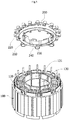
- FIG. 1 is a view illustrating a motor according to example one.
- the motor may include a stator 100, a busbar 200, a rotor 300, and a shaft 400.
- the stator 100 is coupled to a housing 10, and the rotor 300 is disposed inside the stator 100.
- the shaft 400 may be coupled to a center portion of the rotor 300.
- Coils 120 are wound around the stator 100 to have a magnetic pole.
- the rotor 300 is rotated by a magnetic field formed by the winding of the coils 120, and the shaft 400 is rotated at the same time.
- the stator 100 may include a plurality of stator cores 110.
- the stator cores 110 may be formed by stacking a plurality of steel plates which each include a ring-shaped yoke and stator teeth disposed in a circumferential direction and protruding from the yoke toward an inner side in a diameter direction at regular angles.
- the coils 120 that form a rotating magnetic field may be wound around the stator teeth.
- the coils 120 may be insulated by insulators 130.
- Each of the insulators 130 may be coupled to upper and lower sides of the stator cores 110 and insulate so that a current does not flow from the coils 120 wound around the stator teeth to the stator cores 110.
- the insulators 130 may be formed of a resin material.
- An inner circumferential part 130a and an inner circumferential part 130b are respectively provided on an outer circumferential surface side and an inner circumferential surface side of the insulator 130 to prevent the coils 120 from being detached and guide a winding position thereof.
- the busbar 200 may be provided on the stator 100.
- the busbar 200 which connects the coils 120 disposed in parallel, is electrically connected to the coils 120.
- a ring-shaped body 210 made of an insulating material is provided on the busbar 200, and terminals 220 connected to the coils 120 are provided on the body.
- the busbar 200 is connected to the terminals 220 and may supply power to the coils 120 through power terminals receiving external power of mutually different poles.
- the rotor 300 is disposed inside the stator 100.
- the rotor 300 may include a rotor core and a magnet coupled to each other.
- the rotor core and the magnet may be integrally formed.
- the rotor 300 may be formed as a type of rotor in which a magnet is coupled to an outer circumferential surface of a rotor core or a type of rotor in which a magnet may be inserted into a pocket of a rotor core.
- a sensing magnet that obtains position information of the rotor 300 is coupled to a plate and is installed on the rotor 300, or a rotor position sensing unit similar to the sensing magnet may be installed.
- Both ends of the shaft 400 may be rotatably supported by a bearing.
- the motor increases a coupling force between the busbar 200 and the insulators 130 through vibration prevention unit 132.
- the vibration prevention unit 132 is in contact with an inner circumferential surface of the busbar 200 and prevent the busbar 200 from being moved due to vibration.
- vibration prevention units 131 and 132 two types of the vibration prevention units 131 and 132 will be described according to a coupling structure thereof with the busbar 200.
- the vibration prevention unit 131 according to a first modified example
- FIG. 2 is a view illustrating a vibration prevention unit and a slot according to a first modified example
- FIG. 3 is a cross-sectional view illustrating a coupling state of the vibration prevention unit and the slot shown in FIG.2
- FIG. 4 is a view illustrating a state in which the vibration prevention unit shown in FIG. 2 is forcibly inserted into the slot.
- FIGS. 2 to 4 only specified parts are shown for a conceptually clear understanding of a configuration relation of the invention. Accordingly, the drawings may be modified in various forms and may not be significantly limited to a specific form illustrated in the drawings.
- the vibration prevention unit 131 may have a plate shape extending upward from the inner circumferential part 130a of the insulator 130.
- the vibration prevention unit 131 may be formed in a curved plate shape like the inner circumferential part 130a of the insulator 130 so that an outer circumferential surface thereof is in contact with the inner circumferential surface of the insulator 130.
- the vibration prevention unit 131 may be disposed on an upper surface of the inner circumferential part of each of the insulators 130.
- vibration prevention unit 131 may be described as being distinguished from the inner circumferential part 130a of the insulator 130 depending on a shape and functional performance thereof, the vibration prevention unit 131 and the inner circumferential part 130a may be one vertically connected unit.
- a slot 230 into which the vibration prevention unit 131 is inserted may be formed in an inner circumferential surface of the body 210 of the busbar 200.
- the vibration prevention unit 131 may be forcibly inserted into the slot 230 in a height direction thereof, i.e., a z-axis direction of FIG. 3 (a y-axis of FIG.3 is a radial direction of the motor), along guide units 240 disposed on both sides of the slot 230. Sides of the vibration prevention unit 131 are in contact with and rub sides of the guide units 240 in areas A shown in FIG. 3 .
- the busbar 200 which is vulnerable to a fixing force, may be strongly fixed by the insulators 130 without being shaken due to vibration.
- the outer circumferential surface of the vibration prevention unit 131 is in contact with the inner circumferential surface of the busbar 200 provided with the slots 230 and is inserted into the slots 230, and is in contact with and rubs an area B shown in FIG.4 .
- the busbar 200 may be more strongly fixed by contact surfaces between the vibration prevention unit 131 and the guide units 240 and contact surfaces between the slots 230 and the vibration prevention unit 131.
- the guide units 240 protrude inward from the inner circumferential surface of the busbar 200 to divide the slots 230.
- the guide units 240 may be disposed in a circumferential direction at regular intervals. Positions of the guide units 240 may be determined to correspond to positions of the insulators 130.
- a stepped portion 231 may be formed in an area forming an upper edge of the slot 230.
- the stepped portion 231 protrudes inward from an upper end of the inner circumferential surface of the busbar 200 and is in contact with an upper surface of the vibration prevention unit 131.
- a stepped surface of the stepped portion 231 may be horizontally formed, and correspondingly, the upper surface of the vibration prevention unit 131 may also be horizontally formed.
- the vibration prevention unit 132 according to the invention.
- the vibration prevention unit 132 according to the invention will be described with reference to the drawing on the basis of a difference with the vibration prevention unit 131 according to the first modified example.
- FIG. 5 is a view illustrating a vibration prevention unit and a slot according to the present invention
- FIG. 6 is a cross-sectional view illustrating a coupling state of the vibration prevention unit and the slot shown in FIG.5 .
- FIGS. 5 and 6 only specified parts are shown for a conceptually clear understanding of the configuration relation of the invention. Accordingly, the drawing may be modified in various forms and may not be significantly limited to a specific form illustrated in the drawings.
- a hook 132a is formed on an upper end of the vibration prevention unit 132.
- the hook 132a protudes inward from the upper end of the vibration prevention unit 132 toward the center of the motor to form a blocking surface 132b.
- a slot 230 may be formed to pass from a lower end of the inner circumferential surface of the busbar 200 to the upper end thereof.
- the blocking surface 132b of the hook 132a presses the upper end of the inner circumferential surface of the busbar 200 to prevent the busbar from being moved by vibration.
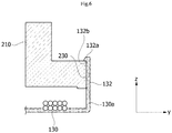
- FIG. 7 is a view illustrating the vibration prevention unit.
- a contact surface 232 of a slot 230 is formed to be inclined by a predetermined angle R from a reference line CL formed in a z-axis direction of FIG 7 . That is, the slot 230 is formed to be inclined toward the center of the body 210 from a y-axis direction.
- a side 132c of the vibration prevention unit 131 is also formed to be inclined.
- the above structure is for securing workability for an assembly of the slot 230 and the vibration prevention unit 132 in consideration of the body 210 of the busbar 200 disposed above the insulators 130.
- a vibration prevention unit connected with an inner circumferential part of an insulator supports an inner circumferential surface of a busbar, and thus a motor can prevent the busbar from moving without an additional process or component to prevent a coating of a coil from being worn or cut.
- a vibration prevention unit is forcibly inserted into a slot formed on an inner circumferential surface of a busbar, and thus a motor can more stably prevent the busbar from moving with a simple assembly process.
Landscapes
- Engineering & Computer Science (AREA)
- Power Engineering (AREA)
- Manufacturing & Machinery (AREA)
- Insulation, Fastening Of Motor, Generator Windings (AREA)
Claims (7)
- Motor umfassend:einen Stator (100) umfassend einen Statorkern (110), eine um den Statorkern (110) gewickelte Spule (120), und einen Isolator (130), der an dem Statorkern (110) montiert und dazu konfiguriert ist, die Spule (120) und den Statorkern (110) zu isolieren;eine Sammelschiene (200), die an dem Stator (100) angeordnet ist und mit der Spule (120) leitend verbunden ist;einen Rotor (300), der innerhalb des Stators (100) angeordnet ist; undeine Welle (400), die mit dem Rotor (300) gekoppelt ist,wobei der Isolator (130) eine Vibrationspräventionseinheit (132) umfasst, die sich von einer oberen Oberfläche eines Innenumfangsteils von diesem nach oben erstreckt und mit einer Innenumfangsoberfläche der Sammelschiene (200) in Kontakt ist,dadurch gekennzeichnet, dass:die Sammelschiene (200) eine Vielzahl von Schlitzen (230) umfasst, die in der Innenumfangsoberfläche von dieser in einer Umfangsrichtung gebildet sind und die Vibrationspräventionseinheit (132) in die Schlitze (230) eingefügt ist, und Führungseinheiten (240) umfasst, die zwischen den angrenzenden Schlitzen (230) angeordnet sind und von der Innenumfangsoberfläche von dieser nach innen vorstehen,wobei Seiten der Vibrationspräventionseinheit (132) mit Seiten der Führungseinheiten (240) in Kontakt sind und sich an diesen reiben,wobei die Vibrationspräventionseinheit (132) einen Haken (132a) umfasst, der an einem oberen Ende von dieser gebildet ist, und der Haken (132a) so gebildet ist, dass er nach innen vorsteht, und der Haken eine Blockieroberfläche (132b) umfasst, die eine obere Oberfläche der Sammelschiene (200) blockiert,wobei die Schlitze (230) so gebildet sind, dass sie in Richtung des Zentrums eines ringförmigen Körpers (210) geneigt sind, der aus einem isolierenden Material hergestellt und an der Sammelschiene (200) vorgesehen ist,wobei eine Seite der Vibrationspräventionseinheit (132) so gebildet ist, dass sie geneigt ist.
- Motor nach Anspruch 1, wobei der Außenumfangsteil der Vibrationspräventionseinheit (132) in Kontakt mit der Innenumfangsoberfläche der Sammelschiene (200) ist.
- Motor nach Anspruch 2, wobei die Vibrationspräventionseinheit (132) in Form einer gekrümmten Platte wie der Innenumfangsteil des Isolators (130) gebildet ist, so dass eine Außenumfangsoberfläche von dieser in Kontakt mit der Innenumfangsoberfläche des Isolators (130) ist.
- Motor nach Anspruch 3, wobei die Führungseinheiten (240) in einer Umfangsrichtung in regelmäßigen Intervallen angeordnet sind und bestimmt ist, dass Positionen der Führungseinheiten (240) Positionen des Isolators (130) entsprechen.
- Motor nach Anspruch 4, wobei die Vibrationspräventionseinheit (132) zwangsweise in den Schlitz eingefügt ist.
- Motor nach Anspruch 1, wobei die Schlitze (230) so gebildet sind, dass sie von einem unteren Ende der Innenumfangsoberfläche der Sammelschiene (200) zu einem oberen Ende von dieser übergehen.
- Motor nach Anspruch 1, wobei die Blockieroberfläche (132b) parallel zur oberen Oberfläche der Sammelschiene (200) ist.
Applications Claiming Priority (2)
| Application Number | Priority Date | Filing Date | Title |
|---|---|---|---|
| KR1020140156397A KR102270422B1 (ko) | 2014-11-11 | 2014-11-11 | 모터 |
| PCT/KR2015/012046 WO2016076599A1 (ko) | 2014-11-11 | 2015-11-10 | 모터 |
Publications (3)
| Publication Number | Publication Date |
|---|---|
| EP3220512A1 EP3220512A1 (de) | 2017-09-20 |
| EP3220512A4 EP3220512A4 (de) | 2017-11-01 |
| EP3220512B1 true EP3220512B1 (de) | 2019-08-07 |
Family
ID=55954621
Family Applications (1)
| Application Number | Title | Priority Date | Filing Date |
|---|---|---|---|
| EP15859982.9A Active EP3220512B1 (de) | 2014-11-11 | 2015-11-10 | Motor |
Country Status (4)
| Country | Link |
|---|---|
| US (3) | US10432060B2 (de) |
| EP (1) | EP3220512B1 (de) |
| KR (1) | KR102270422B1 (de) |
| WO (1) | WO2016076599A1 (de) |
Families Citing this family (15)
| Publication number | Priority date | Publication date | Assignee | Title |
|---|---|---|---|---|
| CN106015010B (zh) * | 2016-07-04 | 2019-02-26 | 珠海凌达压缩机有限公司 | 压缩机定子及压缩机 |
| DE102016121119A1 (de) * | 2016-11-04 | 2018-05-09 | Nidec Corporation | Sammelschieneneinheit für einen Elektromotor |
| KR102364262B1 (ko) * | 2017-07-31 | 2022-02-17 | 엘지이노텍 주식회사 | 모터 |
| JP7192776B2 (ja) * | 2017-09-28 | 2022-12-20 | 日本電産株式会社 | モータ |
| JP6939343B2 (ja) * | 2017-09-28 | 2021-09-22 | 日本電産株式会社 | モータ |
| KR102437465B1 (ko) * | 2017-10-31 | 2022-08-29 | 엘지이노텍 주식회사 | 버스바 및 이를 포함하는 모터 |
| DE102018217858B4 (de) * | 2018-10-18 | 2022-04-21 | Bühler Motor GmbH | Gleichstrommotor und Verfahren zu seiner Herstellung |
| KR102717963B1 (ko) * | 2019-01-11 | 2024-10-16 | 엘지이노텍 주식회사 | 모터 |
| EP3731375B1 (de) | 2019-04-24 | 2023-09-06 | Black & Decker Inc. | Bürstenloser aussenläufermotor mit axiallüfter |
| US12294278B2 (en) * | 2020-03-18 | 2025-05-06 | Lg Innotek Co., Ltd. | Motor |
| US20220109341A1 (en) * | 2020-10-01 | 2022-04-07 | Brose Fahrzeugteile SE & Co. Kommanditgesellschaft, Würzburg | Connection unit for electric motor |
| WO2022086199A1 (ko) * | 2020-10-22 | 2022-04-28 | 엘지이노텍 주식회사 | 모터 |
| DE102020129057A1 (de) * | 2020-11-04 | 2022-05-05 | Schaeffler Technologies AG & Co. KG | Stator |
| CN113437822B (zh) * | 2021-08-06 | 2025-06-10 | 泰信电机(苏州)有限公司 | 一种方便安装的电机线圈 |
| WO2023080757A1 (ko) * | 2021-11-08 | 2023-05-11 | 엘지이노텍 주식회사 | 모터 |
Family Cites Families (11)
| Publication number | Priority date | Publication date | Assignee | Title |
|---|---|---|---|---|
| JP3497684B2 (ja) * | 1996-03-19 | 2004-02-16 | 株式会社東芝 | 回転電機のステータ |
| JPH1070871A (ja) | 1996-08-28 | 1998-03-10 | Matsushita Seiko Co Ltd | ブラシレスモータの固定子 |
| US20080079101A1 (en) | 2006-10-02 | 2008-04-03 | Chi Ai | Insulation frame device for a stator in a motor |
| JP2010028889A (ja) * | 2008-07-15 | 2010-02-04 | Honda Motor Co Ltd | 回転電機 |
| JP2010104211A (ja) * | 2008-10-27 | 2010-05-06 | Mitsuba Corp | ブラシレスモータ |
| KR101829056B1 (ko) | 2010-11-05 | 2018-03-29 | 엘지이노텍 주식회사 | Eps 모터의 버스바 |
| JP2013042633A (ja) * | 2011-08-19 | 2013-02-28 | Nippon Densan Corp | モータ |
| FR2986384B1 (fr) * | 2012-02-01 | 2015-04-10 | Faurecia Bloc Avant | Moteur electrique muni d'une plaque de connexion a crochets |
| JP6098920B2 (ja) * | 2012-10-19 | 2017-03-22 | 日本電産株式会社 | ステータユニットおよびモータ |
| US9502940B2 (en) * | 2013-02-07 | 2016-11-22 | Mitsubishi Electric Corporation | Connection terminal, connection terminal unit, and motor |
| DE102013003024A1 (de) * | 2013-02-22 | 2014-08-28 | Brose Fahrzeugteile GmbH & Co. Kommanditgesellschaft, Würzburg | Elektromotor, insbesondere einer Fahrzeugkomponente |
-
2014
- 2014-11-11 KR KR1020140156397A patent/KR102270422B1/ko not_active Expired - Fee Related
-
2015
- 2015-11-10 US US15/526,098 patent/US10432060B2/en active Active
- 2015-11-10 WO PCT/KR2015/012046 patent/WO2016076599A1/ko not_active Ceased
- 2015-11-10 EP EP15859982.9A patent/EP3220512B1/de active Active
-
2019
- 2019-08-15 US US16/541,782 patent/US10700574B2/en active Active
-
2020
- 2020-05-20 US US16/878,905 patent/US11018551B2/en active Active
Non-Patent Citations (1)
| Title |
|---|
| None * |
Also Published As
| Publication number | Publication date |
|---|---|
| US20190372424A1 (en) | 2019-12-05 |
| US20200287441A1 (en) | 2020-09-10 |
| EP3220512A4 (de) | 2017-11-01 |
| KR20160056232A (ko) | 2016-05-19 |
| US10432060B2 (en) | 2019-10-01 |
| EP3220512A1 (de) | 2017-09-20 |
| KR102270422B1 (ko) | 2021-06-29 |
| US11018551B2 (en) | 2021-05-25 |
| US20170310193A1 (en) | 2017-10-26 |
| US10700574B2 (en) | 2020-06-30 |
| WO2016076599A1 (ko) | 2016-05-19 |
Similar Documents
| Publication | Publication Date | Title |
|---|---|---|
| US11018551B2 (en) | Motor | |
| EP3244514B1 (de) | Motor | |
| US10340753B2 (en) | Stator of planar type motor, and planar type motor using same | |
| KR102514486B1 (ko) | 모터 | |
| JP5866081B1 (ja) | 回転電機及び回転電機用インシュレータ | |
| KR20170003103A (ko) | 인슐레이터 및 이를 포함하는 모터 | |
| US20170353070A1 (en) | Stator assembly for motor | |
| KR102301927B1 (ko) | 스테이터 조립체, 이를 포함하는 모터 및 스테이터 조립체의 제조방법 | |
| JP2018042362A (ja) | ステータユニット、モータ、およびファンモータ | |
| KR20250141683A (ko) | 액츄에이터 | |
| EP2892132B1 (de) | Stromwender für einen Motor und entsprechender Motor | |
| JP2012222944A (ja) | ステータ | |
| KR102554396B1 (ko) | 로터 및 이를 포함하는 모터 | |
| KR102190817B1 (ko) | 모터 및 그 제조방법 | |
| KR102305652B1 (ko) | 모터 | |
| KR102625432B1 (ko) | 버스바 터미널, 버스바, 모터 및 이를 포함하는 차량 | |
| KR102254356B1 (ko) | 버스바 조립체 및 이를 포함하는 모터 | |
| JP6759798B2 (ja) | レゾルバ | |
| KR20220059168A (ko) | 모터 | |
| JP6776850B2 (ja) | 回転電機 | |
| JP2016127614A (ja) | レゾルバステータ構造及びその磁気遮蔽方法 | |
| KR102437464B1 (ko) | 모터의 하우징 및 이를 포함하는 모터 | |
| JP2021019448A (ja) | ステータコア構造 | |
| KR20210014193A (ko) | 모터 | |
| CN109193998A (zh) | 端盖及设有其的电机 |
Legal Events
| Date | Code | Title | Description |
|---|---|---|---|
| STAA | Information on the status of an ep patent application or granted ep patent |
Free format text: STATUS: THE INTERNATIONAL PUBLICATION HAS BEEN MADE |
|
| PUAI | Public reference made under article 153(3) epc to a published international application that has entered the european phase |
Free format text: ORIGINAL CODE: 0009012 |
|
| STAA | Information on the status of an ep patent application or granted ep patent |
Free format text: STATUS: REQUEST FOR EXAMINATION WAS MADE |
|
| 17P | Request for examination filed |
Effective date: 20170524 |
|
| AK | Designated contracting states |
Kind code of ref document: A1 Designated state(s): AL AT BE BG CH CY CZ DE DK EE ES FI FR GB GR HR HU IE IS IT LI LT LU LV MC MK MT NL NO PL PT RO RS SE SI SK SM TR |
|
| AX | Request for extension of the european patent |
Extension state: BA ME |
|
| RIN1 | Information on inventor provided before grant (corrected) |
Inventor name: RYU, WOONG SEON |
|
| A4 | Supplementary search report drawn up and despatched |
Effective date: 20171004 |
|
| RIC1 | Information provided on ipc code assigned before grant |
Ipc: H02K 1/12 20060101AFI20170927BHEP Ipc: H02K 3/52 20060101ALI20170927BHEP |
|
| DAV | Request for validation of the european patent (deleted) | ||
| DAX | Request for extension of the european patent (deleted) | ||
| GRAP | Despatch of communication of intention to grant a patent |
Free format text: ORIGINAL CODE: EPIDOSNIGR1 |
|
| STAA | Information on the status of an ep patent application or granted ep patent |
Free format text: STATUS: GRANT OF PATENT IS INTENDED |
|
| RIC1 | Information provided on ipc code assigned before grant |
Ipc: H02K 3/52 20060101ALI20190121BHEP Ipc: H02K 1/12 20060101AFI20190121BHEP |
|
| INTG | Intention to grant announced |
Effective date: 20190226 |
|
| GRAS | Grant fee paid |
Free format text: ORIGINAL CODE: EPIDOSNIGR3 |
|
| GRAA | (expected) grant |
Free format text: ORIGINAL CODE: 0009210 |
|
| STAA | Information on the status of an ep patent application or granted ep patent |
Free format text: STATUS: THE PATENT HAS BEEN GRANTED |
|
| AK | Designated contracting states |
Kind code of ref document: B1 Designated state(s): AL AT BE BG CH CY CZ DE DK EE ES FI FR GB GR HR HU IE IS IT LI LT LU LV MC MK MT NL NO PL PT RO RS SE SI SK SM TR |
|
| REG | Reference to a national code |
Ref country code: GB Ref legal event code: FG4D |
|
| REG | Reference to a national code |
Ref country code: CH Ref legal event code: EP Ref country code: AT Ref legal event code: REF Ref document number: 1165313 Country of ref document: AT Kind code of ref document: T Effective date: 20190815 |
|
| REG | Reference to a national code |
Ref country code: DE Ref legal event code: R096 Ref document number: 602015035573 Country of ref document: DE |
|
| REG | Reference to a national code |
Ref country code: IE Ref legal event code: FG4D |
|
| REG | Reference to a national code |
Ref country code: NL Ref legal event code: MP Effective date: 20190807 |
|
| REG | Reference to a national code |
Ref country code: LT Ref legal event code: MG4D |
|
| PG25 | Lapsed in a contracting state [announced via postgrant information from national office to epo] |
Ref country code: SE Free format text: LAPSE BECAUSE OF FAILURE TO SUBMIT A TRANSLATION OF THE DESCRIPTION OR TO PAY THE FEE WITHIN THE PRESCRIBED TIME-LIMIT Effective date: 20190807 Ref country code: PT Free format text: LAPSE BECAUSE OF FAILURE TO SUBMIT A TRANSLATION OF THE DESCRIPTION OR TO PAY THE FEE WITHIN THE PRESCRIBED TIME-LIMIT Effective date: 20191209 Ref country code: HR Free format text: LAPSE BECAUSE OF FAILURE TO SUBMIT A TRANSLATION OF THE DESCRIPTION OR TO PAY THE FEE WITHIN THE PRESCRIBED TIME-LIMIT Effective date: 20190807 Ref country code: LT Free format text: LAPSE BECAUSE OF FAILURE TO SUBMIT A TRANSLATION OF THE DESCRIPTION OR TO PAY THE FEE WITHIN THE PRESCRIBED TIME-LIMIT Effective date: 20190807 Ref country code: BG Free format text: LAPSE BECAUSE OF FAILURE TO SUBMIT A TRANSLATION OF THE DESCRIPTION OR TO PAY THE FEE WITHIN THE PRESCRIBED TIME-LIMIT Effective date: 20191107 Ref country code: NL Free format text: LAPSE BECAUSE OF FAILURE TO SUBMIT A TRANSLATION OF THE DESCRIPTION OR TO PAY THE FEE WITHIN THE PRESCRIBED TIME-LIMIT Effective date: 20190807 Ref country code: FI Free format text: LAPSE BECAUSE OF FAILURE TO SUBMIT A TRANSLATION OF THE DESCRIPTION OR TO PAY THE FEE WITHIN THE PRESCRIBED TIME-LIMIT Effective date: 20190807 Ref country code: NO Free format text: LAPSE BECAUSE OF FAILURE TO SUBMIT A TRANSLATION OF THE DESCRIPTION OR TO PAY THE FEE WITHIN THE PRESCRIBED TIME-LIMIT Effective date: 20191107 |
|
| REG | Reference to a national code |
Ref country code: AT Ref legal event code: MK05 Ref document number: 1165313 Country of ref document: AT Kind code of ref document: T Effective date: 20190807 |
|
| PG25 | Lapsed in a contracting state [announced via postgrant information from national office to epo] |
Ref country code: ES Free format text: LAPSE BECAUSE OF FAILURE TO SUBMIT A TRANSLATION OF THE DESCRIPTION OR TO PAY THE FEE WITHIN THE PRESCRIBED TIME-LIMIT Effective date: 20190807 Ref country code: IS Free format text: LAPSE BECAUSE OF FAILURE TO SUBMIT A TRANSLATION OF THE DESCRIPTION OR TO PAY THE FEE WITHIN THE PRESCRIBED TIME-LIMIT Effective date: 20191207 Ref country code: RS Free format text: LAPSE BECAUSE OF FAILURE TO SUBMIT A TRANSLATION OF THE DESCRIPTION OR TO PAY THE FEE WITHIN THE PRESCRIBED TIME-LIMIT Effective date: 20190807 Ref country code: LV Free format text: LAPSE BECAUSE OF FAILURE TO SUBMIT A TRANSLATION OF THE DESCRIPTION OR TO PAY THE FEE WITHIN THE PRESCRIBED TIME-LIMIT Effective date: 20190807 Ref country code: AL Free format text: LAPSE BECAUSE OF FAILURE TO SUBMIT A TRANSLATION OF THE DESCRIPTION OR TO PAY THE FEE WITHIN THE PRESCRIBED TIME-LIMIT Effective date: 20190807 Ref country code: GR Free format text: LAPSE BECAUSE OF FAILURE TO SUBMIT A TRANSLATION OF THE DESCRIPTION OR TO PAY THE FEE WITHIN THE PRESCRIBED TIME-LIMIT Effective date: 20191108 |
|
| PG25 | Lapsed in a contracting state [announced via postgrant information from national office to epo] |
Ref country code: TR Free format text: LAPSE BECAUSE OF FAILURE TO SUBMIT A TRANSLATION OF THE DESCRIPTION OR TO PAY THE FEE WITHIN THE PRESCRIBED TIME-LIMIT Effective date: 20190807 |
|
| PG25 | Lapsed in a contracting state [announced via postgrant information from national office to epo] |
Ref country code: IT Free format text: LAPSE BECAUSE OF FAILURE TO SUBMIT A TRANSLATION OF THE DESCRIPTION OR TO PAY THE FEE WITHIN THE PRESCRIBED TIME-LIMIT Effective date: 20190807 Ref country code: RO Free format text: LAPSE BECAUSE OF FAILURE TO SUBMIT A TRANSLATION OF THE DESCRIPTION OR TO PAY THE FEE WITHIN THE PRESCRIBED TIME-LIMIT Effective date: 20190807 Ref country code: AT Free format text: LAPSE BECAUSE OF FAILURE TO SUBMIT A TRANSLATION OF THE DESCRIPTION OR TO PAY THE FEE WITHIN THE PRESCRIBED TIME-LIMIT Effective date: 20190807 Ref country code: DK Free format text: LAPSE BECAUSE OF FAILURE TO SUBMIT A TRANSLATION OF THE DESCRIPTION OR TO PAY THE FEE WITHIN THE PRESCRIBED TIME-LIMIT Effective date: 20190807 Ref country code: EE Free format text: LAPSE BECAUSE OF FAILURE TO SUBMIT A TRANSLATION OF THE DESCRIPTION OR TO PAY THE FEE WITHIN THE PRESCRIBED TIME-LIMIT Effective date: 20190807 Ref country code: PL Free format text: LAPSE BECAUSE OF FAILURE TO SUBMIT A TRANSLATION OF THE DESCRIPTION OR TO PAY THE FEE WITHIN THE PRESCRIBED TIME-LIMIT Effective date: 20190807 |
|
| PG25 | Lapsed in a contracting state [announced via postgrant information from national office to epo] |
Ref country code: CZ Free format text: LAPSE BECAUSE OF FAILURE TO SUBMIT A TRANSLATION OF THE DESCRIPTION OR TO PAY THE FEE WITHIN THE PRESCRIBED TIME-LIMIT Effective date: 20190807 Ref country code: SK Free format text: LAPSE BECAUSE OF FAILURE TO SUBMIT A TRANSLATION OF THE DESCRIPTION OR TO PAY THE FEE WITHIN THE PRESCRIBED TIME-LIMIT Effective date: 20190807 Ref country code: SM Free format text: LAPSE BECAUSE OF FAILURE TO SUBMIT A TRANSLATION OF THE DESCRIPTION OR TO PAY THE FEE WITHIN THE PRESCRIBED TIME-LIMIT Effective date: 20190807 Ref country code: IS Free format text: LAPSE BECAUSE OF FAILURE TO SUBMIT A TRANSLATION OF THE DESCRIPTION OR TO PAY THE FEE WITHIN THE PRESCRIBED TIME-LIMIT Effective date: 20200224 |
|
| REG | Reference to a national code |
Ref country code: DE Ref legal event code: R097 Ref document number: 602015035573 Country of ref document: DE |
|
| REG | Reference to a national code |
Ref country code: CH Ref legal event code: PL |
|
| PLBE | No opposition filed within time limit |
Free format text: ORIGINAL CODE: 0009261 |
|
| STAA | Information on the status of an ep patent application or granted ep patent |
Free format text: STATUS: NO OPPOSITION FILED WITHIN TIME LIMIT |
|
| PG2D | Information on lapse in contracting state deleted |
Ref country code: IS |
|
| PG25 | Lapsed in a contracting state [announced via postgrant information from national office to epo] |
Ref country code: MC Free format text: LAPSE BECAUSE OF FAILURE TO SUBMIT A TRANSLATION OF THE DESCRIPTION OR TO PAY THE FEE WITHIN THE PRESCRIBED TIME-LIMIT Effective date: 20190807 Ref country code: LU Free format text: LAPSE BECAUSE OF NON-PAYMENT OF DUE FEES Effective date: 20191110 Ref country code: LI Free format text: LAPSE BECAUSE OF NON-PAYMENT OF DUE FEES Effective date: 20191130 Ref country code: CH Free format text: LAPSE BECAUSE OF NON-PAYMENT OF DUE FEES Effective date: 20191130 |
|
| 26N | No opposition filed |
Effective date: 20200603 |
|
| REG | Reference to a national code |
Ref country code: BE Ref legal event code: MM Effective date: 20191130 |
|
| PG25 | Lapsed in a contracting state [announced via postgrant information from national office to epo] |
Ref country code: SI Free format text: LAPSE BECAUSE OF FAILURE TO SUBMIT A TRANSLATION OF THE DESCRIPTION OR TO PAY THE FEE WITHIN THE PRESCRIBED TIME-LIMIT Effective date: 20190807 |
|
| PG25 | Lapsed in a contracting state [announced via postgrant information from national office to epo] |
Ref country code: IE Free format text: LAPSE BECAUSE OF NON-PAYMENT OF DUE FEES Effective date: 20191110 |
|
| PG25 | Lapsed in a contracting state [announced via postgrant information from national office to epo] |
Ref country code: BE Free format text: LAPSE BECAUSE OF NON-PAYMENT OF DUE FEES Effective date: 20191130 |
|
| PG25 | Lapsed in a contracting state [announced via postgrant information from national office to epo] |
Ref country code: CY Free format text: LAPSE BECAUSE OF FAILURE TO SUBMIT A TRANSLATION OF THE DESCRIPTION OR TO PAY THE FEE WITHIN THE PRESCRIBED TIME-LIMIT Effective date: 20190807 |
|
| PG25 | Lapsed in a contracting state [announced via postgrant information from national office to epo] |
Ref country code: MT Free format text: LAPSE BECAUSE OF FAILURE TO SUBMIT A TRANSLATION OF THE DESCRIPTION OR TO PAY THE FEE WITHIN THE PRESCRIBED TIME-LIMIT Effective date: 20190807 Ref country code: HU Free format text: LAPSE BECAUSE OF FAILURE TO SUBMIT A TRANSLATION OF THE DESCRIPTION OR TO PAY THE FEE WITHIN THE PRESCRIBED TIME-LIMIT; INVALID AB INITIO Effective date: 20151110 |
|
| PG25 | Lapsed in a contracting state [announced via postgrant information from national office to epo] |
Ref country code: MK Free format text: LAPSE BECAUSE OF FAILURE TO SUBMIT A TRANSLATION OF THE DESCRIPTION OR TO PAY THE FEE WITHIN THE PRESCRIBED TIME-LIMIT Effective date: 20190807 |
|
| PGFP | Annual fee paid to national office [announced via postgrant information from national office to epo] |
Ref country code: DE Payment date: 20241021 Year of fee payment: 10 |
|
| PGFP | Annual fee paid to national office [announced via postgrant information from national office to epo] |
Ref country code: GB Payment date: 20241021 Year of fee payment: 10 |
|
| PGFP | Annual fee paid to national office [announced via postgrant information from national office to epo] |
Ref country code: FR Payment date: 20241022 Year of fee payment: 10 |