EP3220680A2 - Systèmes et procédés de détection d'anomalie de réseau cellulaire à l'aide des données agrégées dans l'espace - Google Patents
Systèmes et procédés de détection d'anomalie de réseau cellulaire à l'aide des données agrégées dans l'espace Download PDFInfo
- Publication number
- EP3220680A2 EP3220680A2 EP17161358.1A EP17161358A EP3220680A2 EP 3220680 A2 EP3220680 A2 EP 3220680A2 EP 17161358 A EP17161358 A EP 17161358A EP 3220680 A2 EP3220680 A2 EP 3220680A2
- Authority
- EP
- European Patent Office
- Prior art keywords
- data signals
- identifying
- geographic regions
- power value
- interference
- Prior art date
- Legal status (The legal status is an assumption and is not a legal conclusion. Google has not performed a legal analysis and makes no representation as to the accuracy of the status listed.)
- Withdrawn
Links
Images


Classifications
-
- H—ELECTRICITY
- H04—ELECTRIC COMMUNICATION TECHNIQUE
- H04W—WIRELESS COMMUNICATION NETWORKS
- H04W24/00—Supervisory, monitoring or testing arrangements
- H04W24/10—Scheduling measurement reports ; Arrangements for measurement reports
-
- H—ELECTRICITY
- H04—ELECTRIC COMMUNICATION TECHNIQUE
- H04W—WIRELESS COMMUNICATION NETWORKS
- H04W24/00—Supervisory, monitoring or testing arrangements
- H04W24/04—Arrangements for maintaining operational condition
-
- H—ELECTRICITY
- H04—ELECTRIC COMMUNICATION TECHNIQUE
- H04B—TRANSMISSION
- H04B17/00—Monitoring; Testing
- H04B17/30—Monitoring; Testing of propagation channels
- H04B17/309—Measuring or estimating channel quality parameters
- H04B17/318—Received signal strength
- H04B17/328—Reference signal received power [RSRP]; Reference signal received quality [RSRQ]
-
- H—ELECTRICITY
- H04—ELECTRIC COMMUNICATION TECHNIQUE
- H04L—TRANSMISSION OF DIGITAL INFORMATION, e.g. TELEGRAPHIC COMMUNICATION
- H04L41/00—Arrangements for maintenance, administration or management of data switching networks, e.g. of packet switching networks
- H04L41/06—Management of faults, events, alarms or notifications
- H04L41/0604—Management of faults, events, alarms or notifications using filtering, e.g. reduction of information by using priority, element types, position or time
-
- H—ELECTRICITY
- H04—ELECTRIC COMMUNICATION TECHNIQUE
- H04W—WIRELESS COMMUNICATION NETWORKS
- H04W24/00—Supervisory, monitoring or testing arrangements
- H04W24/08—Testing, supervising or monitoring using real traffic
-
- H—ELECTRICITY
- H04—ELECTRIC COMMUNICATION TECHNIQUE
- H04W—WIRELESS COMMUNICATION NETWORKS
- H04W52/00—Power management, e.g. Transmission Power Control [TPC] or power classes
- H04W52/04—Transmission power control [TPC]
- H04W52/30—Transmission power control [TPC] using constraints in the total amount of available transmission power
- H04W52/32—TPC of broadcast or control channels
-
- H—ELECTRICITY
- H04—ELECTRIC COMMUNICATION TECHNIQUE
- H04W—WIRELESS COMMUNICATION NETWORKS
- H04W72/00—Local resource management
- H04W72/20—Control channels or signalling for resource management
- H04W72/21—Control channels or signalling for resource management in the uplink direction of a wireless link, i.e. towards the network
-
- H—ELECTRICITY
- H04—ELECTRIC COMMUNICATION TECHNIQUE
- H04B—TRANSMISSION
- H04B17/00—Monitoring; Testing
- H04B17/30—Monitoring; Testing of propagation channels
- H04B17/309—Measuring or estimating channel quality parameters
- H04B17/336—Signal-to-interference ratio [SIR] or carrier-to-interference ratio [CIR]
-
- H—ELECTRICITY
- H04—ELECTRIC COMMUNICATION TECHNIQUE
- H04W—WIRELESS COMMUNICATION NETWORKS
- H04W16/00—Network planning, e.g. coverage or traffic planning tools; Network deployment, e.g. resource partitioning or cells structures
- H04W16/18—Network planning tools
Definitions
- the present invention relates generally to cellular networks. More particularly, the present invention relates to a systems and methods for cellular network anomaly detection using spatially aggregated data.
- known systems and methods rely on a linearly collected set of data that reflects a user's forward travel through both space and time. Furthermore, known systems and methods rely on the detection of known and predefined events and criteria that match linearly collected events. Such systems and methods can fail to detect some cellular network anomalies because detection cannot occur until an anomaly event occurs and exceeds a known and predefined threshold. Moreover, such systems and methods heavily rely on being in the right place at the right time to capture the anomaly event.
- Embodiments disclosed herein can include systems and methods for cellular network anomaly detection using spatially aggregated data. For example, in some embodiments, data can be captured at multiple times in non-continuous collections, aggregated into data sets, and used to extrapolate anomaly events prior to the event exceeding a predefined threshold. Furthermore, in some embodiments, systems and methods disclosed herein can monitor for and identify changes and fluctuations in overall performance prior to anomaly events degrading to the point of a critical alarm. That is, in some embodiments, burgeoning problem areas can be identified before they fail.
- transceiver device can communicate with and receive signals from one or more cellular networks at multiple, non-continuous times
- the memory device can store the signals received by the transceiver device, data related to the signals received by the transceiver device, and a plurality of predefined threshold values.
- the executable control software can be stored on a transitory or non-transitory computer readable medium, including, but not limited to, local computer memory, RAM, optical storage media, magnetic storage media, flash memory, and the like, and some or all of the control circuitry, the programmable processors, and the control software can execute and control at least some of the methods described herein.
- LTE communications External interference in LTE communications is a major problem for network operators, and such external interference can be found in either the uplink or the downlink of data signals. However, it is typically very difficult for a network operator to identify a physical location of sources of downlink interference.
- some embodiments disclosed herein can include systems and methods for detecting LTE downlink external interference, for example, by identifying areas of external interference using the same set of drive test data that is collected in connection with known systems and methods for, for example, benchmarking, optimization, design, and integration.
- some systems and methods disclosed herein can use a wide dynamic range of RF scanning data to calculate a wideband interfering signal received power (ISRP), which can be derived as a difference of a measured wideband received signal received power (RSRP) and a measured wideband carrier to interference and noise ratio (CINR) for the LTE downlink of data signals. Then, systems and methods disclosed herein can identify areas that have a high ISRP value as compared to a neighboring area and identify such areas as possible locations of high downlink external interference. In some embodiments, systems and methods disclosed herein can also ensure that areas identified as possible locations of high downlink external interference are not in close proximity to a transmitting cellular tower by identifying or referencing threshold values for the RSRP or actual tower location information, when available.
- ISRP wideband interfering signal received power
- RSRP measured wideband received signal received power
- CINR wideband carrier to interference and noise ratio
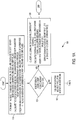
- FIG. 1A and FIG. 1B are flow diagrams of a method 100 for detecting LTE downlink interference in accordance with disclosed embodiments.
- the method 100 can include identifying relevant data as in 110.
- identifying the relevant data as in 110 can include identifying a plurality of bins, wherein each of the plurality of bins includes signals from a respective one of a plurality of geographic areas of a selected size and, for each of the plurality of bins and for each of a plurality of frequency bands on a LTE downlink channel, calculating a best server RSRP value and deriving a corresponding CINR value and a corresponding ISRP value.
- Identifying the relevant data as in 110 can also include calculating a best server RSRP value and deriving a corresponding CINR value and a corresponding ISRP value for a buffer area derived from a buffer area threshold value. Identifying the relevant data as in 110 can also include identifying area locations with a valid carrier RSSI value but null RSRP values and, when the valid carrier RSSI value is greater than -110, assigning an average of carrier RSSI values to the null RSRP values and assigning -30 to CINR values.
- the method 100 can include, for each of the plurality of bins and for each of the plurality of frequency bands on the LTE downlink channel, determining whether a best server RSRP value is less than an RSRP poor coverage threshold value as in 120. If yes, then the method 100 can include classifying a respective one of the plurality of bins as a downlink coverage hole with inadequate coverage, calculating a coverage hole value (CHV) as the best server RSRP value minus an average buffer size RSRP value, assigning a rank for a respective one of a plurality of geographic areas on a map based on the CHV, and displaying coverage holes on the map as C1 ... C10 as in 130, wherein the highest CHV can be assigned C1 to identify the worst coverage hole.
- CHV coverage hole value
- the method 100 determines that the best RSRP value is not less than the RSRP poor coverage threshold value as in 120, then the method can include executing a pilot pollution algorithm and an ISRP algorithm for a respective one of the plurality of bins as in 140. Then, based on the results of executing the algorithms as in 140, the method 100 can include determining whether the respective one of the plurality of bins includes both pilot pollution and interference as in 150.
- the method 100 can include determining whether the best server RSRP value is greater than a good coverage threshold value and whether the best server CINR value is less than a good quality threshold value as in 160. If yes, then the method 100 can include classifying the respective one of the plurality of bins as having a pilot pollution issue and ranking the respective one of the plurality of bins as in 170.
- the method 100 can include classifying the respective one of the plurality of bins as having an interference issue and ranking the respective one of the plurality of bins as in 180.
- the method 100 can include determining whether the respective one of the plurality of bins includes either pilot pollution or ISRP as in 190. If not, then the method 100 can include determining that no issues are found with respect to the respective one of the plurality of bins as in 192. However, if the method 100 determines that the respective one of the plurality of bins includes either pilot pollution or ISRP as in 190, then the method 100 can include ranking each of the plurality of bins for existing problem types based on the plurality of geographic areas on a map and issuing ranking criteria for each of the problem types as in 194.
- the method 100 can include executing a pilot pollution algorithm for a respective one of the plurality of bins as in 140
- FIG. 2 is a flow diagram of a method 200 of analyzing pilot pollution in accordance with disclosed embodiments.
- the method 200 can include, for each of the plurality of bins, calculating a number of measured PCIs and, for each of the measured PCIs other than the best server, calculating whether a PCI RSRP value is greater than the best server RSRP value minus a handover power threshold value and including a respective one of the measured PCIs in a possible server set as in 210.
- the method 200 can include determining whether the number of measured PCIs in the possible server set is greater than a maximum server threshold value and the best server CINR value is less than a good coverage threshold value as in 220. If not, then the method 200 can include classifying the pilot pollution as no pollution as in 230.
- the method 200 can include determining whether the PCI RSRP value for any possible server is greater than or equal to the best server RSRP value minus a dominance power threshold value as in 240. If not, then the method 200 can include classifying the pilot pollution as having too many servers as in 250.
- the method 200 can include classifying the pilot pollution as having a non-dominant server as in 260.
- systems and methods disclosed herein can count the number of non-dominant servers and assign a ranking based thereon, wherein a higher ranking can correspond to bigger issues with more servers in the dominant range.
- systems and methods disclosed herein can count the number of bins with too many servers in a bin and assign a ranking based thereon.
- bins with a non-dominant server can be assigned a higher ranking then bins with too many servers, and in some embodiments, bins within a predetermined radius of a first bin assigned a ranking, for example, 0.1 miles, can be assigned the same ranking.
- the method 100 can include executing an ISRP algorithm for a respective one of the plurality of bins as in 140
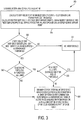
- FIG. 3 is a flow diagram of a method 300 of analyzing external interference in accordance with disclosed embodiments.
- the method 300 can include, for each of the plurality of bins, calculating a best server ISRP value for a respective one of the plurality of bins as the best server RSRP value minus the best server CINR value and, for a buffer size threshold value, calculating a buffer ISRP value as an average of best server RSRP values minus an average of best server CINR values as in 310.
- the best server CINR value can be derived from CINR values with the same cellular identification as the best server RSRP value.
- the method 300 can include determining whether the difference between the best server ISRP value and the buffer ISRP value is greater than an interference threshold value as in 320. If not, then the method 300 can include classifying external interference as no interference as in 330.
- the method 300 can include determining whether network topology information is available as in 340. If not, then the method 300 can include classifying external interference for the respective one of the plurality of bins as in 350 in accordance with the following rules. In some embodiments, the respective one of the plurality of bins can be marked as having external interference, and the distance from the closest emitter and the difference between the best server ISRP value and the buffer ISRP value can determine the interference ranking.
- the interference ranking can be based on only the difference between the best server ISRP value and the buffer ISRP value, and in some embodiments, bins within a predetermined radius of a first bin assigned a ranking, for example, 0.1 miles, can be assigned the same ranking.
- the method 300 can include determining whether the distance to the closest cell site is less than an emitter radius threshold value as in 360. If not, then the method 300 can include classifying external interference for the respective one of the plurality of bins as in 350 and as explained above. However, if the method 300 determines that the distance to the closest cell site is not less than the emitter radius threshold value as in 360, the method 300 can include classifying external interference as no interference as in 330.
- some embodiments disclosed herein can include systems and methods for detecting LTE downlink external interference.
- uplink interference in LTE communication can also occur and be caused by a number of different sources of interference. It can be difficult to locate such sources, both in terms of frequency and physical location because the sources of interference can be continuous or intermittent and can be wideband or narrow band. Nevertheless, for TD-LTE technology in which both uplink and downlink communications are transmitted in the same frequency range, it is essential that sources of interference on the uplink communication be identified with accuracy.
- some systems and methods disclosed herein can include detecting TD-LTE uplink external interference, for example, by identifying the frequency and a possible physical location of a source of interference on the uplink channel.
- systems and methods disclosed herein can use LTE power analysis measurements for TD-LTE technology to identify interference in the uplink communications.
- systems and methods disclosed herein can analyze uplink transmission time based slots across various transmission techniques and identify as possible sources of interference anomalies in the data transmissions that are higher than an expected power level across the time based slots.
- systems and methods can also identify wideband or narrow band sources of interference that are continuous in time or intermittent.
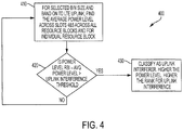
- FIG. 4 is a flow diagram of a method 400 for detecting TD-LTE uplink interference in accordance with disclosed embodiments.
- the method 400 can include, for each of a plurality of bins and for each of a plurality of frequency bands on the TD-LTE uplink channel, calculating the average power level across the transmission time based slots for all resource blocks and for an individual resource block as in 410. Then, the method 400 can include determining whether the average power level for an individual resource block minus the average power level for all resource blocks is greater than an uplink interference threshold value as in 420. If not, then the method 400 can continue calculating as in 410.
- the method 400 can include classifying an uplink interference source as in 430, wherein higher power levels can be assigned a higher ranking for uplink interference sources.
- uplink interference in LTE communication can be caused by a number of different sources of interference.
- sources of interference can be continuous or intermittent and can be wideband or narrow band.
- sources of interference on the uplink communication it is also essential that sources of interference on the uplink communication be identified with accuracy.
- some systems and methods disclosed herein can include detecting FD-LTE uplink external interference, for example, by identifying the frequency and a possible physical location of a source of interference on the uplink channel.
- some systems and methods disclosed herein can use a spectrum analysis to detect an average minimum power value for each of a plurality of bins and for each of a plurality of frequency bands on the FD-LTE uplink channel and, based thereon, identify a maximum power value of average minimum power values across the plurality of bins and the plurality of frequency bins and determine whether the identified value is higher than a predefined interference threshold value for expected user device transmissions.
- systems and methods disclosed herein can calculate a coverage area or range for the identified value in terms of bins and frequencies to identify a geographic area affected by a source of interference and a bandwidth of the source of interference.
- systems and methods disclosed herein can then repeat the above-identified steps to identify other possible sources of interference.
- systems and methods disclosed herein can display on a user interface the top N sources of interference and can receive user input to rank each of the displayed sources or to filter the displayed sources according to a time range to distinguish between the origination and the resolution of sources of interference, when applicable.
- power values for each of a plurality of frequencies can be divided into different ones of a plurality of bins based on geography so that values from the same geographic region are grouped in the same bin. Then, a minimum power value of each of the plurality of bins for each of the plurality of frequencies can be identified, and the one of the plurality of bins and the one of the plurality of frequencies with the maximum power value of all of the identified minimum power values can be identified as a possible source of interference.
- Table 1 illustrates an exemplary matrix in accordance with disclosed embodiments and shows the identified minimum power value of the highest point in the matrix as -95 in Bin 2 and the 709.06 frequency range.
- the possible source of interference can be located in a geographic region corresponding to Bin 2 and operate in the 709.06 frequency range.
- Table 1 Frequency Range (RBW 15KHz) 709.015 709.03 709.045 709.06 709.075 ...n
- systems and methods can determine whether the identified value of the highest point in the matrix is higher than a predefined interference threshold, for example, -100.
- a predefined interference threshold for example, -100.
- systems and methods disclosed herein can evaluate the coverage area of the identified possible source of interference in terms of bandwidth and distance to identify points until which the minimum values as identified above for each data point are higher than the predefined interference threshold.
- the points surrounding the identified minimum power value of the highest point in the matrix that are higher than the predefined interference threshold can be in Bin 2 and the 709.045 frequency range (-97), in Bin 2 and the 709.075 frequency range (-98), in Bin 3 and the 709.045 frequency range (-99), in Bin 3 and the 709.06 frequency range (-96), and in Bin 3 and the 709.075 frequency range (-99).
- the coverage area of the possible source of interference can include the geographic regions corresponding to Bin 2 and Bin 3 and operate in the 709.045, 709.06, and 709.075 frequency ranges.
- a second identified minimum power value in the matrix of -98 can be identified in Bin 3 in the 709.015 frequency range, and a point surrounding the second identified minimum power value that is higher than the predefined interference threshold can be in Bin 4 and the 709.015 frequency range (-99).
- the second possible source of interference can be located in a geographic region corresponding to Bin 3 and operate in the 709.015 frequency range, and the coverage area of the second possible source of interference can cover the geographic area corresponding to Bin 3 and Bin 4 and operate in the 709.015 frequency range.
- the top N identified possible sources of interference can be ranked according to their identified minimum values, and the ranked minimum values and their corresponding coverage size and bandwidth can be displayed on a user interface.
- the bandwidth corresponding to each identified minimum power value can be calculated on either side of a center frequency by counting frequency bins on each side of the center frequency and multiplying by a respective resolution bandwidth value, and the size of the geographic area affected by the possible source of interference can be calculated by summing the identified bins.
Landscapes
- Engineering & Computer Science (AREA)
- Computer Networks & Wireless Communication (AREA)
- Signal Processing (AREA)
- Quality & Reliability (AREA)
- Physics & Mathematics (AREA)
- Electromagnetism (AREA)
- Mobile Radio Communication Systems (AREA)
- Environmental & Geological Engineering (AREA)
Applications Claiming Priority (2)
| Application Number | Priority Date | Filing Date | Title |
|---|---|---|---|
| US201662309262P | 2016-03-16 | 2016-03-16 | |
| US15/459,695 US20170272305A1 (en) | 2016-03-16 | 2017-03-15 | Systems and methods for cellular network anomaly detection using spatially aggregated data |
Publications (2)
| Publication Number | Publication Date |
|---|---|
| EP3220680A2 true EP3220680A2 (fr) | 2017-09-20 |
| EP3220680A3 EP3220680A3 (fr) | 2017-11-08 |
Family
ID=58448310
Family Applications (1)
| Application Number | Title | Priority Date | Filing Date |
|---|---|---|---|
| EP17161358.1A Withdrawn EP3220680A3 (fr) | 2016-03-16 | 2017-03-16 | Systèmes et procédés de détection d'anomalie de réseau cellulaire à l'aide des données agrégées dans l'espace |
Country Status (3)
| Country | Link |
|---|---|
| US (1) | US20170272305A1 (fr) |
| EP (1) | EP3220680A3 (fr) |
| CN (1) | CN107205242A (fr) |
Families Citing this family (6)
| Publication number | Priority date | Publication date | Assignee | Title |
|---|---|---|---|---|
| US10334287B2 (en) * | 2017-04-17 | 2019-06-25 | Plex, Inc. | Digital data streaming using server driven adaptive bitrate |
| WO2020154514A1 (fr) * | 2019-01-25 | 2020-07-30 | Endura Technologies | Procédé et appareil de réseau de communication sur ligne électrique |
| US11876569B2 (en) * | 2019-05-15 | 2024-01-16 | Astrapi Corporation | Devices, systems, and software including signal power measuring and methods and software for measuring signal power |
| CN110839256B (zh) * | 2019-09-26 | 2020-11-10 | 西安交通大学 | 一种蜂窝网络数据异常检测方法 |
| CN116801374A (zh) * | 2022-03-11 | 2023-09-22 | 中国移动通信集团设计院有限公司 | 异常干扰源的识别方法、系统、终端设备及介质 |
| US20240155362A1 (en) * | 2022-11-09 | 2024-05-09 | T-Mobile Innovations Llc | Machine learning-based system and method for determining service coverage and peformance solutions with precise location deployment |
Family Cites Families (8)
| Publication number | Priority date | Publication date | Assignee | Title |
|---|---|---|---|---|
| GB2481614B (en) * | 2010-06-30 | 2017-11-22 | Fujitsu Ltd | Coverage hole compensation in wireless communication networks |
| US9049720B2 (en) * | 2012-07-30 | 2015-06-02 | Lg Electronics Inc. | Method and apparatus for simultaneously performing frequency resource sensing and data transmission in a wireless communication system |
| US9532252B2 (en) * | 2012-12-04 | 2016-12-27 | At&T Intellectual Property I, L.P. | Diagnosis of cellular network element states using radio frequency measurements |
| US20140219117A1 (en) * | 2013-02-07 | 2014-08-07 | Qualcomm Incorporated | Apparatus and method for inter cell interference coordination |
| US9572055B2 (en) * | 2013-04-09 | 2017-02-14 | Spectrum Effect, Inc. | Uplink interference detection using transmission matrices |
| US20140302796A1 (en) * | 2013-04-09 | 2014-10-09 | Eden Rock Communications, Llc | Downlink interference detection using transmission matrices |
| EP3075185B1 (fr) * | 2013-11-29 | 2024-08-07 | Telefonaktiebolaget LM Ericsson (publ) | Commande de fonctionnement de réseau cellulaire au moyen d'une métrique à base d'interférences |
| CN104918287B (zh) * | 2015-06-15 | 2018-09-25 | 厦门大学 | 一种负载均衡的方法及装置 |
-
2017
- 2017-03-15 US US15/459,695 patent/US20170272305A1/en not_active Abandoned
- 2017-03-16 CN CN201710195854.3A patent/CN107205242A/zh not_active Withdrawn
- 2017-03-16 EP EP17161358.1A patent/EP3220680A3/fr not_active Withdrawn
Non-Patent Citations (1)
| Title |
|---|
| None |
Also Published As
| Publication number | Publication date |
|---|---|
| EP3220680A3 (fr) | 2017-11-08 |
| US20170272305A1 (en) | 2017-09-21 |
| CN107205242A (zh) | 2017-09-26 |
Similar Documents
| Publication | Publication Date | Title |
|---|---|---|
| US20170272305A1 (en) | Systems and methods for cellular network anomaly detection using spatially aggregated data | |
| US10461791B2 (en) | Interference analysis in wireless networks | |
| US10374882B2 (en) | Systems and methods for identifying causes of quality degradation in wireless networks | |
| Datla et al. | A spectrum surveying framework for dynamic spectrum access networks | |
| CN104853379B (zh) | 一种无线网络质量评估方法及装置 | |
| CN109495895B (zh) | 信道带宽选择 | |
| US8140068B2 (en) | Techniques for feedback in cellular systems to mitigate interference in downlink | |
| CN103581957B (zh) | 一种干扰检测方法、设备及系统 | |
| EP3101933B1 (fr) | Procédé et appareil d'attribution d'identifiants de cellules physiques | |
| US10440660B2 (en) | Uplink spectrum analysis technique for passive intermodulation (PIM) detection | |
| JP2019531030A5 (fr) | ||
| JP7140267B2 (ja) | 無線通信品質可視化装置および無線通信品質可視化システム | |
| US20140301216A1 (en) | Uplink interference detection using transmission matrices | |
| WO2017202144A1 (fr) | Procédé et appareil permettant de distinguer des utilisateurs intérieurs et extérieurs, et support de stockage | |
| CN108243448B (zh) | 一种小区系统内干扰强度的确定方法及装置 | |
| EP3355606B1 (fr) | Procédé et dispositif de détection d'intensité de signal | |
| CN107154829A (zh) | 确定无线通信系统中上行自系统干扰的方法和装置 | |
| CN104427532B (zh) | 频点带内干扰的获取方法及装置 | |
| JP5152176B2 (ja) | 無線セル監視方法、その装置及びそのプログラム | |
| CN108243447B (zh) | 一种外部干扰的定位方法及装置 | |
| CN106535205B (zh) | 频率重耕小区设置方法及系统 | |
| CN109981196B (zh) | 一种网络结构评估方法及装置 | |
| CN111263389A (zh) | 一种Volte语音质量问题的自动化定位的方法及装置 | |
| US6393277B1 (en) | System and method for identifying a source of interference in a mobile telecommunications network | |
| CN117749294A (zh) | 干扰检测方法、基站及存储介质 |
Legal Events
| Date | Code | Title | Description |
|---|---|---|---|
| PUAI | Public reference made under article 153(3) epc to a published international application that has entered the european phase |
Free format text: ORIGINAL CODE: 0009012 |
|
| STAA | Information on the status of an ep patent application or granted ep patent |
Free format text: STATUS: THE APPLICATION HAS BEEN PUBLISHED |
|
| AK | Designated contracting states |
Kind code of ref document: A2 Designated state(s): AL AT BE BG CH CY CZ DE DK EE ES FI FR GB GR HR HU IE IS IT LI LT LU LV MC MK MT NL NO PL PT RO RS SE SI SK SM TR |
|
| AX | Request for extension of the european patent |
Extension state: BA ME |
|
| PUAL | Search report despatched |
Free format text: ORIGINAL CODE: 0009013 |
|
| AK | Designated contracting states |
Kind code of ref document: A3 Designated state(s): AL AT BE BG CH CY CZ DE DK EE ES FI FR GB GR HR HU IE IS IT LI LT LU LV MC MK MT NL NO PL PT RO RS SE SI SK SM TR |
|
| AX | Request for extension of the european patent |
Extension state: BA ME |
|
| RIC1 | Information provided on ipc code assigned before grant |
Ipc: H04W 24/10 20090101AFI20171002BHEP Ipc: H04B 17/345 20150101ALN20171002BHEP Ipc: H04W 16/18 20090101ALN20171002BHEP Ipc: H04B 17/336 20150101ALN20171002BHEP |
|
| REG | Reference to a national code |
Ref country code: HK Ref legal event code: DE Ref document number: 1236311 Country of ref document: HK |
|
| STAA | Information on the status of an ep patent application or granted ep patent |
Free format text: STATUS: THE APPLICATION IS DEEMED TO BE WITHDRAWN |
|
| 18D | Application deemed to be withdrawn |
Effective date: 20180509 |
|
| REG | Reference to a national code |
Ref country code: HK Ref legal event code: WD Ref document number: 1236311 Country of ref document: HK |