EP3220714B1 - Funksteuerungsvorrichtung, endgerätevorrichtung und kommunikationsverfahren - Google Patents
Funksteuerungsvorrichtung, endgerätevorrichtung und kommunikationsverfahren Download PDFInfo
- Publication number
- EP3220714B1 EP3220714B1 EP15858596.8A EP15858596A EP3220714B1 EP 3220714 B1 EP3220714 B1 EP 3220714B1 EP 15858596 A EP15858596 A EP 15858596A EP 3220714 B1 EP3220714 B1 EP 3220714B1
- Authority
- EP
- European Patent Office
- Prior art keywords
- terminal
- communication
- band
- base station
- terminal device
- Prior art date
- Legal status (The legal status is an assumption and is not a legal conclusion. Google has not performed a legal analysis and makes no representation as to the accuracy of the status listed.)
- Active
Links
Images




Classifications
-
- H—ELECTRICITY
- H04—ELECTRIC COMMUNICATION TECHNIQUE
- H04W—WIRELESS COMMUNICATION NETWORKS
- H04W76/00—Connection management
- H04W76/10—Connection setup
- H04W76/14—Direct-mode setup
-
- H—ELECTRICITY
- H04—ELECTRIC COMMUNICATION TECHNIQUE
- H04W—WIRELESS COMMUNICATION NETWORKS
- H04W16/00—Network planning, e.g. coverage or traffic planning tools; Network deployment, e.g. resource partitioning or cells structures
- H04W16/14—Spectrum sharing arrangements between different networks
-
- H—ELECTRICITY
- H04—ELECTRIC COMMUNICATION TECHNIQUE
- H04W—WIRELESS COMMUNICATION NETWORKS
- H04W24/00—Supervisory, monitoring or testing arrangements
- H04W24/10—Scheduling measurement reports ; Arrangements for measurement reports
-
- H—ELECTRICITY
- H04—ELECTRIC COMMUNICATION TECHNIQUE
- H04W—WIRELESS COMMUNICATION NETWORKS
- H04W72/00—Local resource management
- H04W72/04—Wireless resource allocation
-
- H—ELECTRICITY
- H04—ELECTRIC COMMUNICATION TECHNIQUE
- H04W—WIRELESS COMMUNICATION NETWORKS
- H04W72/00—Local resource management
- H04W72/04—Wireless resource allocation
- H04W72/044—Wireless resource allocation based on the type of the allocated resource
- H04W72/0446—Resources in time domain, e.g. slots or frames
-
- H—ELECTRICITY
- H04—ELECTRIC COMMUNICATION TECHNIQUE
- H04W—WIRELESS COMMUNICATION NETWORKS
- H04W72/00—Local resource management
- H04W72/04—Wireless resource allocation
- H04W72/044—Wireless resource allocation based on the type of the allocated resource
- H04W72/0453—Resources in frequency domain, e.g. a carrier in FDMA
-
- H—ELECTRICITY
- H04—ELECTRIC COMMUNICATION TECHNIQUE
- H04W—WIRELESS COMMUNICATION NETWORKS
- H04W72/00—Local resource management
- H04W72/20—Control channels or signalling for resource management
- H04W72/23—Control channels or signalling for resource management in the downlink direction of a wireless link, i.e. towards a terminal
-
- H—ELECTRICITY
- H04—ELECTRIC COMMUNICATION TECHNIQUE
- H04W—WIRELESS COMMUNICATION NETWORKS
- H04W92/00—Interfaces specially adapted for wireless communication networks
- H04W92/16—Interfaces between hierarchically similar devices
- H04W92/18—Interfaces between hierarchically similar devices between terminal devices
-
- H—ELECTRICITY
- H04—ELECTRIC COMMUNICATION TECHNIQUE
- H04W—WIRELESS COMMUNICATION NETWORKS
- H04W76/00—Connection management
- H04W76/20—Manipulation of established connections
- H04W76/23—Manipulation of direct-mode connections
Definitions
- the present invention relates to a terminal device and a communication method and, more particularly, to a terminal device and a communication method for performing direct communication between terminal devices in a wireless communication system.
- D2D communication Evolved Universal Terrestrial Radio Access Network
- D2D communication is executed using, for example, some of radio resources used in uplink of cellular communication such as LTE.
- the distance between terminal devices to which the D2D communication can be applied is said to be several hundred m.
- 3GPP (3rd Generation Partnership Project) Release 12 a method of causing a terminal device to detect a terminal located in the vicinity and a method of broadcasting data to unspecified terminal devices have been proposed (for example, see NPL 1 or 2).
- WO 2012/068731 A1 discloses a method whereby, to find a D2D channel (e.g. a shared channel for offload traffic from an allocated D2D channel), a cellular network access node sends a configuration message with parameters (e.g. sensing time, frequency band, sensing mechanism, cyclic shift) for a D2D device to sense spectrum. From the results of this spectrum sensing is decided whether to utilize a frequency band, sensed according to the parameters, for D2D communications.
- parameters e.g. sensing time, frequency band, sensing mechanism, cyclic shift
- WO 2014/111868 A2 discloses systems and methods for network-assisted device discovery for D2D communications.
- a base station in a cellular communications network receives a D2D request from a first wireless device to establish D2D communication, and in response to the D2D request the base station selects a second wireless device for D2D communication with the first wireless device based on the D2D request and information regarding wireless devices that are available for D2D communication.
- the base station transmits a D2D request acknowledgment to the first wireless device that includes information that enables the first wireless device to establish D2D communication with the second wireless device.
- the base station also effects transmission of a D2D reconfiguration message to the second wireless device, where the D2D reconfiguration message includes information that informs the second wireless device that the first wireless device has requested establishment of D2D communication.
- WO 2014/111896 A2 discloses systems and methods related to D2D communication in a cellular communications network.
- a base station obtains D2D capability information for wireless devices, where the D2D capability information indicates that the wireless devices are physically capable of D2D communication.
- the base station also receives a D2D request from a first wireless device and, in response, determines that a D2D initialization procedure is to be performed.
- the base station transmits a positive D2D decision to the first wireless device that includes information that enables the first wireless device to establish D2D communication with a second wireless device, where the second wireless device is one of the wireless devices that are physically capable of D2D communication.
- the present invention has been made in consideration of the above-described problem, and has as its object to provide a terminal device, and a communication method for implementing high continuity of terminal device-to-terminal device communication.
- the present invention provides a terminal device as defined in Claim 1 of the appended claims, and a communication method as defined in Claim 2.
- a radio control device for controlling terminal-to-terminal communication in which a plurality of terminal devices perform direct wireless communication without an intervention of a base station device, comprising control means for assigning a frequency band unsupported by the base station device as a radio resource usable for the terminal-to-terminal communication, and wireless communication means for transmitting resource information about the radio resource assigned by the control means to the terminal devices.
- the wireless communication means further transmits information about at least one service type permitted in the terminal-to-terminal communication using the radio resource assigned by the control means.
- the wireless communication means may transmit the resource information by a broadcast channel.
- the wireless communication means may transmit, as the resource information, information about a frequency resource and/or information about a time resource.
- the radio control device includes, for example, E-UTRAN, and means a concept including a base station device or a host apparatus thereof.
- the control means may assign the radio resource to each terminal device, and the wireless communication means may transmit, by a dedicated channel, the resource information for designating the radio resource assigned to each terminal device.
- the wireless communication means may receive measurement information about radio quality reported by the terminal device, the control means may determine, based on the measurement information from the terminal device, whether to switch the assigned radio resource, and upon determining to switch the radio resource, generate switching information about switching, and the wireless communication means may transmit the switching information generated by the control means to the terminal device.
- the wireless communication means may receive measurement information about radio quality reported by the terminal device, and the control means may determine, based on the measurement information from the terminal device, whether to switch the assigned radio resource, and upon determining not to switch the radio resource, inhibit transmission of switching information about switching to the terminal device. Based on a service type, which is to be performed in the terminal-to-terminal communication and is requested by the terminal device, the control means may assign a radio resource to be used for the service type.
- a terminal device for performing terminal-to-terminal communication in which a plurality of terminal devices directly perform wireless communication without an intervention of a base station device, the terminal device comprising: communication means for receiving resource information for designating a frequency band unsupported by the base station device as a radio resource usable for the terminal-to-terminal communication; and control means for determining whether the terminal device can handle the radio resource designated by the resource information, and if the terminal device can handle the radio resource, executing the terminal-to-terminal communication using the radio resource, and if the terminal device cannot handle the radio resource, executing the terminal-to-terminal communication using a usable radio resource supported by the base station device and permitted to be used for the terminal-to-terminal communication.
- the terminal device can handle the radio resource designated by the resource information, it can continuously execute terminal-to-terminal communication using the radio resource. It is also possible to effectively use an unused band and save use of a radio resource of cellular communication.
- a communication method in a communication system including a plurality of terminal devices and a radio control device for controlling terminal-to-terminal communication in which the plurality of terminal devices directly perform wireless communication without an intervention of a base station device, the method comprising: in the radio control device, assigning a frequency band unsupported by the base station device as a radio resource usable for the terminal-to-terminal communication; and transmitting resource information for designating the assigned radio resource to the terminal devices, and in the terminal device, receiving the resource information; and determining whether the terminal device can handle the radio resource designated by the resource information, and if the terminal device can handle the radio resource, executing the terminal-to-terminal communication using the radio resource, and if the terminal device cannot handle the radio resource, executing the terminal-to-terminal communication using a radio resource usable for the terminal-to-terminal communication in a frequency band supported by the base station device.
- the present invention it is possible to provide a terminal device, and a communication method for implementing high continuity of terminal-to-terminal communication and enabling effective use of radio resources.
- a radio control device assigns a frequency band that is not supported by a base station device as a radio resource usable for D2D communication, and transmits resource information that designates the assigned radio resource to a terminal device.
- the terminal device determines whether the terminal device can handle the radio resource designated by the resource information. If the terminal device can handle the radio resource, device-to-device communication is executed using the radio resource. If the terminal device cannot handle the radio resource, device-to-device communication is executed using a radio resource usable for device-to-device communication in a frequency band supported by the base station device.
- the above-described D2D communication technique is a technique of performing direct communication between the terminal devices without an intervention of a base station. Since a base station need not always exist to execute the D2D communication, the above-described installation of a base station can be implemented without cost.
- the band cannot be used for communication in an area where a small area is not deployed.
- a terminal device cannot know that the band is usable for D2D communication.
- the band can be used an independent ad hoc band. In this case as well, if the band becomes unusable, the communication cannot be continued.
- the present invention solves the above-described problems. It is possible to dynamically change the radio resource from the wireless network side and appropriately manage the band used to execute device-to-device communication. It is therefore possible to provide device-to-device communication holding high communication continuity and also effectively use the radio resource.
- Fig. 1 is a block diagram showing an example of the arrangement of a wireless communication system according to an embodiment of the present invention.
- a wireless communication system 100 includes a first terminal device 10, a second terminal device 20, and a base station device (E-UTRAN) 30 that constitutes a wireless access network of an LTE system.
- E-UTRAN base station device
- the base station device 30 supports a band f1 for cellular communication.
- the first terminal device 10 and the second terminal device 20 are located in the cell area of the band f1, and can perform cellular communication with the base station device 30 using the band f1.
- the first terminal device 10 and the second terminal device 20 are terminals capable of executing device-to-device communication (D2D communication) without an intervention of the base station device 30.
- the first terminal device 10 and the second terminal device 20 are assumed to be in an RRC_CONNECTED state to the base station device 30 here.
- the RRC_CONNECTED state is a state in which the base station device manages radio resources, and the terminal devices can transmit/receive data. In this state, functions such as data transmission/reception and feedback of information such as CQI (Channel Quality Indicator) to the base station device can be executed.
- CQI Channel Quality Indicator
- the base station device 30 can transmit, to the first terminal device 10 and the second terminal device 20, a notification (resource information) that allows them to use, in D2D communication, a radio resource in a band f2 unsupported by the base station.
- a notification resource information
- the first terminal device 10 and the second terminal device 20 can execute D2D communication with each other using the radio resource in the band f2. This makes it possible to effectively use an unused band and save use of a radio resource of cellular communication.
- “supported/unsupported” includes that a device does not have a communication function for the band, and also includes that a device has the communication function but is not allowed to use the band.
- the present invention is not limited to the above-described arrangement, and at least one of the first terminal device 10 and the second terminal device 20 needs to be in the RRC_CONNECTED state to the base station device 30.
- the first terminal device 10 may receive the notification representing the permission of use of the radio resource in the band f2 for D2D communication from the base station device 30, and not the base station device 30 but the first terminal device 10 may notify the second terminal device 20 that the band f2 is usable. This also applies to examples to be described later.
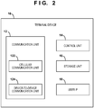
- Fig. 2 is a block diagram showing an example of the arrangement of a terminal device used as the first terminal device 10 and the second terminal device 20 shown in Fig. 1 .
- the terminal device includes a communication unit 12, a control unit 14, a storage unit 16, and a user interface (user IF) 18.
- user IF user interface
- the communication unit 12 includes a cellular communication unit 122 and a device-to-device communication unit 124.
- the cellular communication unit 122 performs wireless communication with the base station device 30.
- the device-to-device communication unit 124 directly communicates with a terminal device as the partner of D2D communication without an intervention of the base station device 30 using a radio resource for D2D communication assigned by the base station device. These communication processes may be done using a known modulation/demodulation technology or antenna technology.
- the storage unit 16 may store data transmitted from the base station device 30 or the terminal device as the partner of D2D communication, or may store data that is obtained via the user IF 18 and should be transmitted to the base station device 30 or the terminal device as the partner of D2D communication.
- the user IF 18 may include a screen interface, an input interface such as an operation button or a touch panel configured to receive an input from the user, and an image capturing means such as a camera.
- the control unit 14 is formed by, for example, a CPU and generally controls the units using information received from the cellular communication unit 122 or the device-to-device communication unit 124 or information stored in the storage unit 16.
- the control unit 14 determines whether the terminal device can handle the radio resource of the band f2 designated by the resource information. If the terminal device can handle the band f2, the control unit 14 controls execution of D2D communication with the terminal device of the partner by the device-to-device communication unit 124. If the terminal device cannot handle the band f2, and a radio resource usable for D2D communication in the band f1 supported by the base station device 30 is notified in advance by a control message or the like from the base station device 30, D2D communication can be executed using the radio resource of the band f1.
- control unit 14 measures the radio quality of the downlink for each cell of the base station device 30 and base station devices on the periphery using a radio signal received by the cellular communication unit 122. Also, the control unit 14 may transmit/receive a known signal to/from the partner in device-to-device communication, thereby measuring radio quality for a radio resource used in the device-to-device communication. For example, in the LTE system, RSRP (Reference Signal Received Power) and/or RSRQ (Reference Signal Received Quality) of a reference signal is measured as radio quality. The control unit 14 reports radio quality information including a measurement target such as the identifier (ID) of each cell and measured radio quality to the base station device 30 as needed.
- ID the identifier
- Fig. 3 is a block diagram showing an example of the arrangement of the base station device 30 shown in Fig. 1 .
- the base station device 30 includes a communication unit 32, a control unit 34, and a storage unit 36.
- the communication unit 32 includes a wireless communication unit 322 and a network communication unit 324.
- the wireless communication unit 322 executes wireless cellular communication using a predetermined cellular method with each of the first terminal device 10 and the second terminal device 20 both of which belong to the cell area of the local station while the control unit 34 uses information stored in the storage unit 36.
- the network communication unit 324 executes inter-base station communication with another adjacent base station device via an X2 interface or the like.
- the storage unit 36 stores TDD config information and the like acquired from another adjacent base station device via the network communication unit 324.
- the wireless communication unit 322 transmits resource information about a radio resource assigned by the control unit 34 to the terminal devices.
- the resource information may be transmitted by broadcast using a broadcast channel or may be transmitted to a specific terminal device using a dedicated channel.
- the resource information may include information about a frequency resource and/or information about a time resource.
- the wireless communication unit 322 may receive measurement information about radio quality reported from each terminal device and transmit switching information generated by the control unit 34 based on the measurement information to the terminal device.
- the wireless communication unit 322 may further transmit information about one or more service types permitted in device-to-device communication using the radio resource assigned by the control unit 34. Note that details of the service types will be described later.
- the control unit 34 notifies a radio resource usable for D2D communication in the band f1 supported by the base station device 30 to the first terminal device 10 and the second terminal device 20 by a control message or the like.
- the control unit 34 can also assign the band f2 unsupported by the base station device 30 as a radio resource usable for D2D communication and transmit resource information that designates the assigned radio resource to the first terminal device 10 and the second terminal device 20.
- the resource information can be broadcast by a broadcast channel to terminal devices located in the cell area of the band f1.
- the control unit 34 may assign the radio resource of the band f2 for each terminal device and transmit resource information that designates the radio resource assigned for each terminal device by a dedicated channel.
- the control unit 34 may determine based on measurement information reported from each terminal device whether to switch the assigned radio resource. Upon determining to switch the radio resource, the control unit 34 may generate switching information concerning switching. The switching information may include information about the radio resource of the switching destination. Additionally, based on a service type of device-to-device communication, which is requested by a terminal device, the control unit 34 may assign a radio resource to be used for the service type. Note that the term “switch” may be replaced with a term such as "change”, “correct”, “transit”, “shift”, “exchange”, “substitute”, “set”, or "reconfigure".
- a QCI QoS Class Identifier
- the base station device 30 stores information (QCI table) about the QCI in the storage unit 36 in advance.
- the control unit 34 can assign the radio resource of the band f2 or band f1 based on the class (QCI) of service quality (QoS) requested in D2D communication.
- the resource information can include, for example, band information usable for D2D communication, a frequency resource region in the band, EARFCN (E-UTRAN absolute radio frequency channel number), the bandwidth of a radio resource for D2D, a system frame number, setting information of a retransmission control format designation channel (PHICH), or a downlink bandwidth, or an arbitrary combination of the above-described pieces of information.
- band information usable for D2D communication a frequency resource region in the band
- EARFCN E-UTRAN absolute radio frequency channel number
- the bandwidth of a radio resource for D2D a system frame number
- setting information of a retransmission control format designation channel (PHICH) a retransmission control format designation channel (PHICH), or a downlink bandwidth
- Example 1 of the present invention will be described with reference to Figs. 4 to 7 .
- a first terminal device 10 and a second terminal device 20 exist in the cell area of a band f1 supported by a base station device 30.
- resource information including one or both of band information of a band f2 unsupported by the base station and a frequency resource region in the band f2 is included in a broadcast channel from the base station device 30 of the cell and notified to the first terminal device 10 and the second terminal device 20 as a radio resource usable for D2D communication.
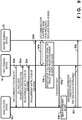
- Fig. 4 is a sequence chart showing an example of the operation of a wireless communication system according to Example 1.
- the base station device 30 notifies the first terminal device 10 and the second terminal device 20, by broadcast, of resource information (D2D resource information) which designates the band f2 unsupported by the base station as a radio resource usable for D2D communication and is included in an SIB (System Information Block) (steps S1a and S1b).
- D2D resource information resource information which designates the band f2 unsupported by the base station as a radio resource usable for D2D communication and is included in an SIB (System Information Block) (steps S1a and S1b).
- SIB System Information Block
- D2D resource information is band information usable for D2D communication, a frequency resource region in the band, the bandwidth of a radio resource for D2D, a system frame number, setting information of a retransmission control format designation channel (PHICH), or a downlink bandwidth, or an arbitrary combination of the above-described pieces of information.
- PHICH retransmission control format designation channel
- the band information can be notified by, for example, a band specifier.
- the band specifier indicates specifiers f1, f2, f3,..., fn corresponding to different frequency bands in advance.
- a specifier for example, a band indicator described in reference 1 ( TS36.101 Ver.12.0.0, July 2013 ) or a carrier frequency number designated by EARFCN (E-UTRAN absolute radio frequency channel number) described in reference 2 (TS36.104) is usable.
- a D2D frequency band specifier in the frequency direction and a resource assignment specifier in the time direction can be designated and thus notified.
- only the D2D frequency band specifier in the frequency direction or only the resource assignment specifier in the time direction can be notified.
- the D2D frequency band specifier is a specifier that adds an index (RB index) to each resource block (RB) in the band in the frequency direction and notifies an index range (a start RB index and an end RB index) representing resource blocks intended to be assigned for D2D, as shown in Fig. 5.
- Fig. 5 shows an example in which if the frequency band specifier includes a start RB index "3" and an end RB index "7", a frequency resource region represented by a hatched pattern is designated as a resource for D2D.
- the resource assignment specifier in the time direction is a specifier representing the start offset (start radio frame index) of a radio frame capable of using a UL subframe in the radio frame for D2D and a D2D radio frame assignment period, as shown in Fig. 6.
- Fig. 6 shows an example in which if the resource assignment specifier in the time direction includes a start radio frame index "1" and a D2D radio frame assignment period "6", a UL subframe represented by a horizontal line pattern of a radio frame represented by a hatched pattern is designated as a resource for D2D.
- the resource assignment specifier in the time direction is a specifier representing a subframe number usable for D2D, the start offset of a radio frame, and a D2D radio frame assignment period.
- each of the first terminal device 10 and the second terminal device 20 performs processing shown in the flowchart of Fig. 7 , thereby executing D2D communication in the band f2 notified in steps S1a and S1b or in the frequency resource region in the band f2 (step S1c).
- each of the first terminal device 10 and the second terminal device 20 first determines whether the terminal can handle the band f2 designated by the D2D resource information (step S2a). If the terminal can handle the band f2, D2D communication is started using the designated resource based on the D2D resource information (step S2b). On the other hand, if the terminal cannot handle the band f2, the terminal device determines whether a frequency resource region for D2D in the band f1 supported by the base station device 30 that is currently executing cellular communication is designated by the base station device 30 (step S2c). If a frequency resource region is designated, D2D communication is started using the designated resource in the band f1 currently under the cellular communication (step S2d).
- step S2e If a frequency resource region for D2D in the band f1 is not designated by the base station device 30, the terminal device cancels the start of D2D communication and notifies the base station device 30 of the abnormal end (step S2e).
- the notification of the abnormal end in step S2e may be omitted.
- the base station device notifies broadcast information including a D2D resource information in the band unsupported by the base station.
- the terminal device executes device-to-device communication using the radio resource if it can handle the band designated by the resource information. This makes it possible to, for example, effectively use an unused band in the cell and save the use of a radio resource in cellular communication.
- Example 2 of the present invention will be described with reference to Figs. 8 , 9 , 10A , and 10B .
- Example 2 is a modification of Example 1, and is different from Example 1 in that D2D resource information notified by broadcast using an SIB or the like is notified by a dedicated channel such as RRC signaling.
- Fig. 8 is a block diagram showing an example of the arrangement of a wireless communication system according to Example 2.
- a wireless communication system 110 a first terminal device 10 and a second terminal device 20 exist in the cell area of a band f1 supported by a base station device 30, as in Fig. 1 .
- D2D communication using a band f2 can be executed between the first terminal device 10 and the second terminal device 20 based on resource information notified by the base station device 30.
- Example 2 assumes a case in which the first terminal device 10 that is executing D2D communication by the band f2 moves close to the cell area of a base station device 40 that supports the band f2 for cellular communication to cause interference in the D2D communication.
- Example 1 since a notification is made by broadcast using an SIB, it is impossible to notify different D2D resource information to each terminal device.
- Example 2 it is possible to notify different D2D resource information to each terminal device by RRC signaling. Accordingly, in an area in which the base station device 40 that supports the band f2 for cellular communication and the base station device 30 that does not support the band f2 coexist, the band to execute D2D communication can dynamically be changed in accordance with the location of each terminal device or the result of measurement by each terminal device. This can suppress erroneous use of an unintended band by the terminal device.
- Fig. 9 is a sequence chart showing an example of the operation of the wireless communication system according to Example 2.
- the first terminal device 10 transmits, to the base station device 30, a request signal to start D2D communication with the second terminal device 20 (step S3a).
- the base station device 30 Upon receiving the request signal in step S3a, the base station device 30 notifies, by RRC signaling, D2D resource information that designates the band f2 unsupported by the base station or a frequency resource region in the band f2 as a radio resource usable for D2D communication (step S3b).
- the base station device 30 also transmits a measurement instruction of the D2D band f2 to the first terminal device 10 and the second terminal device 20 (steps S3c and S3d).
- Each of the first terminal device 10 and the second terminal device 20 performs the processing shown in the flowchart of Fig. 7 , thereby executing D2D communication in the band f2 notified in step S3b or in the frequency resource region in the band f2 (step S3e).
- the first terminal device 10 and the second terminal device 20 measure the radio quality of a downlink for each cell of the base station device 30 and base station devices on the periphery. Then, the state shown in Fig. 8 is formed.
- the first terminal device 10 Upon receiving a cell reference signal of a predetermined power or more from the base station device 40 in the D2D band f2 (step S3f), the first terminal device 10 transmits a signal (measurement report) concerning a measurement report to the base station device 30 (step S3g).
- the measurement report can include an RSRP value or RSRQ value measured in step S3f.
- the base station device 30 uses the measurement report in step S3g as a trigger to perform a band transition (step S3h). Based on the band reconfiguration decision, a D2D resource pool reconfiguration to notify the change of the D2D resource information is transmitted using a dedicated channel for each terminal device (steps S3i and S3j). For example, if an unused band f3 exists, the base station device 30 notifies the first terminal device 10 and the second terminal device 20, which are performing D2D communication, of D2D resource information including the band information of the band f3, thereby making a transition from the band f2 to the band f3. Note that upon deciding not to make a band transition in the band reconfiguration decision of step S3h, the base station device 30 does not transmit the D2D resource information change notification in steps S3i and S3j.
- the band used to execute D2D communication by a terminal can be changed for each terminal device, as in steps S3i and S3j.
- the base station device 30 determines whether to make a band transition in accordance with an arbitrary combination of conditions Alt.1 to Alt.4 to be described below, and executes transition processing.
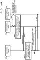
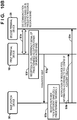
- Figs. 10A and 10B show the procedure of band transition processing of Alt.4.
- Fig. 10A shows a case in which no neighbor is established with respect to the cell (for example, a 3.5-GHz cell) of the base station device 40 adjacent to the base station device 30.
- Fig. 10B shows a case in which a neighbor is established with respect to the cell of the base station device 40 adjacent to the base station device 30.
- steps S3e to S3g in Figs. 10A and 10B represent the same processes as those of steps S3e to S3g in Fig. 9 .
- step S4a upon receiving a measurement report in step S3g, as described with reference to Fig. 9 , if the RSRP value or RSRQ value in the different band cell (f2) included in the measurement report is equal to or larger than a predetermined threshold (step S4a), the base station device 30 instructs the first terminal device 10 and the second terminal device 20 to comply with the TDD config in the different band cell (steps S4b and S4c).
- the terminal device is made to autonomously avoid the D1 subframe of the band f2. Note that if determining in step S4a that the RSRP value or RSRQ value in the different band cell (f2) is not equal to or larger than the predetermined threshold, the base station device 30 does not issue the instruction in steps S4b and S4c.
- the base station device 30 upon receiving a measurement report in step S3g, as described with reference to Fig. 9 , if the RSRP value or RSRQ value in the different band cell (f2) included in the measurement report is equal to or larger than a predetermined threshold (step S5a), the base station device 30 notifies the first terminal device 10 and the second terminal device 20 of resource pool information according to the TDD config of the adjacent cell (steps S5b and S5c). For example, if a neighbor is established with respect to the cell of the band f2 of the base station device 40 adjacent to the base station device 30, the TDD config information of the base station device 40 in the cell can be acquired via the X2 interface.
- the base station device notifies, by RRC signaling, resource information according to the acquired TDD config information. Note that if determining in step S5a that the RSRP value or RSRQ value in the different band cell (f2) is not equal to or larger than the predetermined threshold, the base station device 30 does not make the notification in steps S5b and S5c.
- Example 2 it is possible to dynamically change a radio resource from the wireless network side and appropriately manage the band used to execute D2D communication. It is therefore possible to provide D2D communication holding high communication continuity and also effectively use a radio resource.
- Example 3 of the present invention will be described with reference to Figs. 11 to 13 .
- Example 3 is a modification of Examples 1 and 2.
- bands used to execute D2D communication are divided in consideration of QoS (Quality of Service). This makes it possible to provide appropriate radio quality according to a service request for each terminal device.
- QoS Quality of Service
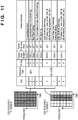
- Example 3 bands used to execute D2D communication or resource pool regions are linked for each QCI (QoS Class Identifier) described in reference 3 ( TS23.203 Ver.13.0.1, June 2014 ).
- QCI 1 to QCI 4 are linked with a D2D execution band f2
- QCI 5 to QCI 9 are linked with a D2D execution band f1. That is, for a terminal device that executes a service classified into GBR (Guaranteed Bit Rate) traffic, a band in which cellular communication does not exist is designated to increase the degree of freedom in resource assignment.
- GBR Guard Bit Rate
- a D2D resource in a band in which cellular communication coexists is designated to do D2D resource assignment with priority on cellular communication.
- a QCI table shown in Fig. 11 is not limited to this and can arbitrarily be set. The QCI table may appropriately be changed by, for example, determining the degree of congestion of each band in the base station.
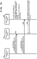
- Fig. 12 is a sequence chart showing an example of the operation of a wireless communication system according to Example 3 based on Example 1.
- the base station device 30 notifies, by an SIB, the first terminal device 10 and the second terminal device 20 of D2D resource information including band information usable for D2D or a frequency resource region in the band and an ID (for example, QCI) for identifying a D2D service type or service type permitted in each band (steps S6a and S6b).
- ID for example, QCI
- QCI 1 to QCI 4 are linked with the D2D execution band f2 and notified.
- Each of the first terminal device 10 and the second terminal device 20 collates the QCI notified by the D2D resource information with the type of the service of D2D traffic performed by the local terminal, and executes D2D communication in a corresponding band (step S6c).
- Fig. 13 is a sequence chart showing an example of the operation of the wireless communication system according to Example 3 based on Example 2.
- the first terminal device 10 transmits, to the base station device 30, a request signal to start D2D communication with the second terminal device 20 (step S7a).
- information about the type of a service performed by the local terminal is included in the D2D communication request signal and notified to the base station device 30 for appropriate band determination in the base station device 30.
- the information about the type of the service can include, for example, a service type or an ID (for example, QCI) for identifying the service type.
- the base station device 30 designates, for each user by RRC signaling, a band appropriately usable by the terminal device to execute D2D communication of the service type (step S7b).
- the base station device 30 transmits a measurement instruction for the D2D band to the first terminal device 10 and the second terminal device 20 (steps S7c and S7d).
- Each of the first terminal device 10 and the second terminal device 20 performs processing shown in the flowchart of Fig. 7 , thereby executing D2D communication in the band notified in step S7b or in the frequency resource region in the band (step S7e).
- Example 3 it is possible to assign an optimum radio resource to be used to execute D2D communication in accordance with a service type requested in the D2D communication. It is also possible to appropriately manage the band used to execute D2D communication and effectively use the radio resource.
Landscapes
- Engineering & Computer Science (AREA)
- Computer Networks & Wireless Communication (AREA)
- Signal Processing (AREA)
- Mobile Radio Communication Systems (AREA)
Claims (2)
- Endvorrichtung (10; 20) zum Durchführen einer Kommunikation von Endvorrichtung zu Endvorrichtung, bei der mehrere Endvorrichtungen (10, 20) direkt eine drahtlose Kommunikation ohne einen Eingriff einer Basisstationsvorrichtung (30) durchführen, wobei die Endvorrichtung Folgendes umfasst:ein Kommunikationsmittel (122) zum Empfangen von Ressourceninformationen zum Bestimmen eines Frequenzbandes, das von der Basisstationsvorrichtung (30) nicht unterstützt wird, als eine Funkressource, die für die Kommunikation von Endvorrichtung zu Endvorrichtung verwendbar ist; undein Steuermittel (14) zum Bestimmen, ob die Endvorrichtung in der Lage ist, die durch die Ressourceninformationen bezeichnete Funkressource zu handhaben, und wenn die Endvorrichtung in der Lage ist, die Funkressource zu handhaben, Steuern der Kommunikation von Endvorrichtung zu Endvorrichtung unter Verwendung der Funkressource, und wenn die Endvorrichtung nicht in der Lage ist, die Funkressource zu handhaben, Steuern der Kommunikation von Endvorrichtung zu Endvorrichtung unter Verwendung einer verwendbaren Funkressource, die von der Basisstationsvorrichtung (30) unterstützt wird und für die Kommunikation von Endvorrichtung zu Endvorrichtung verwendet werden darf.
- Kommunikationsverfahren in einem Kommunikationssystem, das Folgendes umfasst: eine Vielzahl von Endvorrichtungen (10, 20) und eine Funksteuervorrichtung zum Steuern der Kommunikation von Endvorrichtung zu Endvorrichtung, bei der die Vielzahl von Endvorrichtungen (10, 20) direkt eine drahtlose Kommunikation ohne einen Eingriff einer Basisstationsvorrichtung (30) durchführen, wobei das Verfahren Folgendes umfasst:in der Funksteuervorrichtung,Zuweisen eines von der Basisstationsvorrichtung (30) nicht unterstützten Frequenzbandes als Funkressource, die für die Kommunikation von Endvorrichtung zu Endvorrichtung verwendet werden kann; undÜbertragen von Ressourceninformationen zum Bestimmen der zugewiesenen Funkressource an die Endvorrichtungen (10, 20) undin der Endvorrichtung,Empfangen der Ressourceninformationen; undBestimmen, ob die Endvorrichtung in der Lage ist, die durch die Ressourceninformationen bezeichnete Funkressource zu handhaben, und wenn die Funkvorrichtung die Ressource der Endvorrichtung handhabt, hat die Ausführung die Fähigkeit der Kommunikation von Endvorrichtung zu Endvorrichtung unter Verwendung der Funkressource, und wenn die Endvorrichtung nicht in der Lage ist, die Funkressource zu handhaben, Ausführen der Kommunikation von Endvorrichtung zu Endvorrichtung unter Verwendung einer Funkressource, die für die Kommunikation von Endvorrichtung zu Endvorrichtung im Frequenzband verwendbar ist, das von der Basisstationsvorrichtung (30) unterstützt wird.
Applications Claiming Priority (2)
| Application Number | Priority Date | Filing Date | Title |
|---|---|---|---|
| JP2014232085A JP2016096475A (ja) | 2014-11-14 | 2014-11-14 | 無線制御装置、端末装置、および通信方法 |
| PCT/JP2015/081804 WO2016076378A1 (ja) | 2014-11-14 | 2015-11-12 | 無線制御装置、端末装置および通信方法 |
Publications (3)
| Publication Number | Publication Date |
|---|---|
| EP3220714A1 EP3220714A1 (de) | 2017-09-20 |
| EP3220714A4 EP3220714A4 (de) | 2017-11-22 |
| EP3220714B1 true EP3220714B1 (de) | 2020-01-15 |
Family
ID=55954456
Family Applications (1)
| Application Number | Title | Priority Date | Filing Date |
|---|---|---|---|
| EP15858596.8A Active EP3220714B1 (de) | 2014-11-14 | 2015-11-12 | Funksteuerungsvorrichtung, endgerätevorrichtung und kommunikationsverfahren |
Country Status (5)
| Country | Link |
|---|---|
| US (1) | US10555353B2 (de) |
| EP (1) | EP3220714B1 (de) |
| JP (1) | JP2016096475A (de) |
| CN (1) | CN107006072B (de) |
| WO (1) | WO2016076378A1 (de) |
Families Citing this family (12)
| Publication number | Priority date | Publication date | Assignee | Title |
|---|---|---|---|---|
| KR20190002449A (ko) * | 2016-04-29 | 2019-01-08 | 광동 오포 모바일 텔레커뮤니케이션즈 코포레이션 리미티드 | 장비 간 통신 방법 및 장치 |
| US11159932B1 (en) | 2016-09-16 | 2021-10-26 | Apple Inc. | Electronic devices with intuitive sharing capabilities |
| US11076261B1 (en) * | 2016-09-16 | 2021-07-27 | Apple Inc. | Location systems for electronic device communications |
| US11147074B2 (en) | 2016-11-25 | 2021-10-12 | Guangdong Oppo Mobile | Data transmission method and apparatus |
| US10091784B1 (en) * | 2016-12-31 | 2018-10-02 | Sprint Communications Company L.P. | Device-to-device (D2D) scheduling control in orthogonal frequency division multiplexing (OFDM) wireless system |
| CN110121909B (zh) * | 2017-01-25 | 2022-04-12 | 华为技术有限公司 | 一种业务数据传输方法、第一通信节点及基站 |
| WO2020039487A1 (ja) * | 2018-08-20 | 2020-02-27 | 富士通株式会社 | 端末装置、基地局装置、及び通信システム |
| JP7116341B2 (ja) * | 2018-09-19 | 2022-08-10 | 富士通株式会社 | 通信装置、基地局装置、及び通信システム |
| JP6889141B2 (ja) * | 2018-11-15 | 2021-06-18 | 株式会社Kddi総合研究所 | 制御装置、基地局装置、端末装置、制御方法、及びプログラム |
| CN111510920B (zh) * | 2019-01-31 | 2021-11-19 | 华为技术有限公司 | 连接管理的方法和设备 |
| US12238752B2 (en) | 2019-12-16 | 2025-02-25 | Telefonaktiebolaget Lm Ericsson (Publ) | Reliable device-to-device communication |
| US11653383B2 (en) * | 2020-03-23 | 2023-05-16 | Qualcomm Incorporated | Techniques for performing random access procedures in sidelink wireless communications |
Family Cites Families (11)
| Publication number | Priority date | Publication date | Assignee | Title |
|---|---|---|---|---|
| WO2012068731A1 (en) * | 2010-11-25 | 2012-05-31 | Nokia Corporation | Network assisted sensing on a shared band for local communications |
| EP2566079B1 (de) * | 2011-08-31 | 2013-10-02 | Alcatel Lucent | Verfahren zum Koordinieren von mindestens einer ersten Übertragung von einem Einzelpunktsender zu einem Einzelpunktempfänger und mindestens einer zweiten Übertragung von einem Mehrpunktsender oder zu einem Mehrpunktempfänger in einem Funkkommunikationssystem, und entsprechende Mobilstation |
| AU2012376802A1 (en) * | 2012-04-11 | 2014-10-02 | Intel Corporation | Operator-assisted device-to-device (D2D) discovery |
| JP5939299B2 (ja) * | 2012-05-31 | 2016-06-22 | 富士通株式会社 | 無線通信システム、無線基地局装置、端末装置、及び無線リソースの割り当て方法 |
| JP2014014038A (ja) * | 2012-07-05 | 2014-01-23 | Kddi Corp | パラメータ調整装置、及びパラメータ調整プログラム |
| US9313607B2 (en) * | 2013-01-18 | 2016-04-12 | Telefonaktiebolaget L M Ericsson (Publ) | Network-assisted UE detection in direct mode UE-to-UE communication |
| US20140204847A1 (en) * | 2013-01-18 | 2014-07-24 | Telefonaktiebolaget L M Ericsson (Publ) | Network-assisted d2d communication using d2d capability information |
| EP2785092B1 (de) * | 2013-03-28 | 2015-09-23 | Fujitsu Limited | Drahtloses Kommunikationssystem |
| JP5864034B2 (ja) * | 2013-10-11 | 2016-02-17 | 京セラ株式会社 | 通信制御方法、ユーザ端末及び通信装置 |
| JP2015126393A (ja) * | 2013-12-26 | 2015-07-06 | 株式会社Nttドコモ | ユーザ端末、無線基地局、無線通信システムおよび無線通信方法 |
| KR102073902B1 (ko) * | 2014-08-07 | 2020-02-05 | 엘지전자 주식회사 | 무선 통신 시스템에서 단말에 의해 수행되는 d2d(device-to-device) 동작 방법 및 상기 방법을 이용하는 단말 |
-
2014
- 2014-11-14 JP JP2014232085A patent/JP2016096475A/ja active Pending
-
2015
- 2015-11-12 EP EP15858596.8A patent/EP3220714B1/de active Active
- 2015-11-12 WO PCT/JP2015/081804 patent/WO2016076378A1/ja not_active Ceased
- 2015-11-12 CN CN201580061707.6A patent/CN107006072B/zh active Active
-
2017
- 2017-05-11 US US15/593,074 patent/US10555353B2/en active Active
Non-Patent Citations (1)
| Title |
|---|
| None * |
Also Published As
| Publication number | Publication date |
|---|---|
| CN107006072B (zh) | 2020-12-18 |
| EP3220714A1 (de) | 2017-09-20 |
| CN107006072A (zh) | 2017-08-01 |
| US20170251510A1 (en) | 2017-08-31 |
| EP3220714A4 (de) | 2017-11-22 |
| JP2016096475A (ja) | 2016-05-26 |
| WO2016076378A1 (ja) | 2016-05-19 |
| US10555353B2 (en) | 2020-02-04 |
Similar Documents
| Publication | Publication Date | Title |
|---|---|---|
| EP3220714B1 (de) | Funksteuerungsvorrichtung, endgerätevorrichtung und kommunikationsverfahren | |
| KR102083322B1 (ko) | 이동 통신 시스템에서 고립 사용자 단말기에 대한 디바이스-투-디바이스 통신 기반 서비스 제공 장치 및 방법 | |
| EP3496434B1 (de) | Terminal-zu-terminal kommunikation | |
| CN109041137B (zh) | 一种切换的方法、基站及终端设备 | |
| JP5981671B2 (ja) | 基地局、ユーザ端末及びプロセッサ | |
| US10004104B2 (en) | Mobile communication system, base station, user terminal, and processor | |
| RU2713508C2 (ru) | Устройство связи, оборудование инфраструктуры, сеть мобильной связи и способы | |
| EP2906009B1 (de) | Drahtloses kommunikationssystem, basisstation und kommunikationssteuerungsverfahren | |
| EP3197233B1 (de) | Verfahren zur steuerung des zugangs zu einem drahtlosnetzwerk, erstes basisstation und system | |
| EP3010273A1 (de) | Funkressourcenverwaltung in einem Telekommunikationssystem | |
| JP2017538380A (ja) | 資源配置方法及びシステム、並びに基地局機能を有するデバイス及び端末 | |
| US20230370882A1 (en) | Wireless communication devices, network connection nodes, systems and methods | |
| CN114846849A (zh) | 集成接入和回程网络中标识符的管理 | |
| WO2016059063A1 (en) | Selecting the qci of a connection of an aggregator device | |
| EP3207729B1 (de) | Steuerungseinheit, kommunikationsgerät, system und entsprechende verfahren | |
| EP4305804A1 (de) | Funknetzwerkknoten, netzwerkknoten und darin durchgeführte verfahren | |
| JP6766232B2 (ja) | 基地局装置、端末装置、および通信方法 | |
| JP6422744B2 (ja) | 基地局及び無線通信制御方法 | |
| JP2018006905A (ja) | 無線通信システム、基地局、移動局及び識別番号設定方法 | |
| JP2016072856A (ja) | 基地局装置、端末装置、通信方法、および通信システム |
Legal Events
| Date | Code | Title | Description |
|---|---|---|---|
| STAA | Information on the status of an ep patent application or granted ep patent |
Free format text: STATUS: THE INTERNATIONAL PUBLICATION HAS BEEN MADE |
|
| PUAI | Public reference made under article 153(3) epc to a published international application that has entered the european phase |
Free format text: ORIGINAL CODE: 0009012 |
|
| STAA | Information on the status of an ep patent application or granted ep patent |
Free format text: STATUS: REQUEST FOR EXAMINATION WAS MADE |
|
| 17P | Request for examination filed |
Effective date: 20170420 |
|
| AK | Designated contracting states |
Kind code of ref document: A1 Designated state(s): AL AT BE BG CH CY CZ DE DK EE ES FI FR GB GR HR HU IE IS IT LI LT LU LV MC MK MT NL NO PL PT RO RS SE SI SK SM TR |
|
| AX | Request for extension of the european patent |
Extension state: BA ME |
|
| A4 | Supplementary search report drawn up and despatched |
Effective date: 20171023 |
|
| RIC1 | Information provided on ipc code assigned before grant |
Ipc: H04W 92/18 20090101AFI20171017BHEP Ipc: H04W 16/14 20090101ALI20171017BHEP Ipc: H04W 72/04 20090101ALI20171017BHEP |
|
| DAV | Request for validation of the european patent (deleted) | ||
| DAX | Request for extension of the european patent (deleted) | ||
| STAA | Information on the status of an ep patent application or granted ep patent |
Free format text: STATUS: EXAMINATION IS IN PROGRESS |
|
| 17Q | First examination report despatched |
Effective date: 20180604 |
|
| GRAP | Despatch of communication of intention to grant a patent |
Free format text: ORIGINAL CODE: EPIDOSNIGR1 |
|
| STAA | Information on the status of an ep patent application or granted ep patent |
Free format text: STATUS: GRANT OF PATENT IS INTENDED |
|
| INTG | Intention to grant announced |
Effective date: 20190807 |
|
| GRAS | Grant fee paid |
Free format text: ORIGINAL CODE: EPIDOSNIGR3 |
|
| GRAA | (expected) grant |
Free format text: ORIGINAL CODE: 0009210 |
|
| STAA | Information on the status of an ep patent application or granted ep patent |
Free format text: STATUS: THE PATENT HAS BEEN GRANTED |
|
| AK | Designated contracting states |
Kind code of ref document: B1 Designated state(s): AL AT BE BG CH CY CZ DE DK EE ES FI FR GB GR HR HU IE IS IT LI LT LU LV MC MK MT NL NO PL PT RO RS SE SI SK SM TR |
|
| REG | Reference to a national code |
Ref country code: CH Ref legal event code: EP Ref country code: GB Ref legal event code: FG4D |
|
| REG | Reference to a national code |
Ref country code: IE Ref legal event code: FG4D |
|
| REG | Reference to a national code |
Ref country code: DE Ref legal event code: R096 Ref document number: 602015045794 Country of ref document: DE |
|
| REG | Reference to a national code |
Ref country code: AT Ref legal event code: REF Ref document number: 1226298 Country of ref document: AT Kind code of ref document: T Effective date: 20200215 |
|
| REG | Reference to a national code |
Ref country code: NL Ref legal event code: MP Effective date: 20200115 |
|
| REG | Reference to a national code |
Ref country code: LT Ref legal event code: MG4D |
|
| PG25 | Lapsed in a contracting state [announced via postgrant information from national office to epo] |
Ref country code: NL Free format text: LAPSE BECAUSE OF FAILURE TO SUBMIT A TRANSLATION OF THE DESCRIPTION OR TO PAY THE FEE WITHIN THE PRESCRIBED TIME-LIMIT Effective date: 20200115 Ref country code: RS Free format text: LAPSE BECAUSE OF FAILURE TO SUBMIT A TRANSLATION OF THE DESCRIPTION OR TO PAY THE FEE WITHIN THE PRESCRIBED TIME-LIMIT Effective date: 20200115 Ref country code: FI Free format text: LAPSE BECAUSE OF FAILURE TO SUBMIT A TRANSLATION OF THE DESCRIPTION OR TO PAY THE FEE WITHIN THE PRESCRIBED TIME-LIMIT Effective date: 20200115 Ref country code: PT Free format text: LAPSE BECAUSE OF FAILURE TO SUBMIT A TRANSLATION OF THE DESCRIPTION OR TO PAY THE FEE WITHIN THE PRESCRIBED TIME-LIMIT Effective date: 20200607 Ref country code: NO Free format text: LAPSE BECAUSE OF FAILURE TO SUBMIT A TRANSLATION OF THE DESCRIPTION OR TO PAY THE FEE WITHIN THE PRESCRIBED TIME-LIMIT Effective date: 20200415 |
|
| PG25 | Lapsed in a contracting state [announced via postgrant information from national office to epo] |
Ref country code: LV Free format text: LAPSE BECAUSE OF FAILURE TO SUBMIT A TRANSLATION OF THE DESCRIPTION OR TO PAY THE FEE WITHIN THE PRESCRIBED TIME-LIMIT Effective date: 20200115 Ref country code: SE Free format text: LAPSE BECAUSE OF FAILURE TO SUBMIT A TRANSLATION OF THE DESCRIPTION OR TO PAY THE FEE WITHIN THE PRESCRIBED TIME-LIMIT Effective date: 20200115 Ref country code: BG Free format text: LAPSE BECAUSE OF FAILURE TO SUBMIT A TRANSLATION OF THE DESCRIPTION OR TO PAY THE FEE WITHIN THE PRESCRIBED TIME-LIMIT Effective date: 20200415 Ref country code: GR Free format text: LAPSE BECAUSE OF FAILURE TO SUBMIT A TRANSLATION OF THE DESCRIPTION OR TO PAY THE FEE WITHIN THE PRESCRIBED TIME-LIMIT Effective date: 20200416 Ref country code: IS Free format text: LAPSE BECAUSE OF FAILURE TO SUBMIT A TRANSLATION OF THE DESCRIPTION OR TO PAY THE FEE WITHIN THE PRESCRIBED TIME-LIMIT Effective date: 20200515 Ref country code: HR Free format text: LAPSE BECAUSE OF FAILURE TO SUBMIT A TRANSLATION OF THE DESCRIPTION OR TO PAY THE FEE WITHIN THE PRESCRIBED TIME-LIMIT Effective date: 20200115 |
|
| REG | Reference to a national code |
Ref country code: DE Ref legal event code: R097 Ref document number: 602015045794 Country of ref document: DE |
|
| PG25 | Lapsed in a contracting state [announced via postgrant information from national office to epo] |
Ref country code: SM Free format text: LAPSE BECAUSE OF FAILURE TO SUBMIT A TRANSLATION OF THE DESCRIPTION OR TO PAY THE FEE WITHIN THE PRESCRIBED TIME-LIMIT Effective date: 20200115 Ref country code: EE Free format text: LAPSE BECAUSE OF FAILURE TO SUBMIT A TRANSLATION OF THE DESCRIPTION OR TO PAY THE FEE WITHIN THE PRESCRIBED TIME-LIMIT Effective date: 20200115 Ref country code: LT Free format text: LAPSE BECAUSE OF FAILURE TO SUBMIT A TRANSLATION OF THE DESCRIPTION OR TO PAY THE FEE WITHIN THE PRESCRIBED TIME-LIMIT Effective date: 20200115 Ref country code: SK Free format text: LAPSE BECAUSE OF FAILURE TO SUBMIT A TRANSLATION OF THE DESCRIPTION OR TO PAY THE FEE WITHIN THE PRESCRIBED TIME-LIMIT Effective date: 20200115 Ref country code: DK Free format text: LAPSE BECAUSE OF FAILURE TO SUBMIT A TRANSLATION OF THE DESCRIPTION OR TO PAY THE FEE WITHIN THE PRESCRIBED TIME-LIMIT Effective date: 20200115 Ref country code: RO Free format text: LAPSE BECAUSE OF FAILURE TO SUBMIT A TRANSLATION OF THE DESCRIPTION OR TO PAY THE FEE WITHIN THE PRESCRIBED TIME-LIMIT Effective date: 20200115 Ref country code: ES Free format text: LAPSE BECAUSE OF FAILURE TO SUBMIT A TRANSLATION OF THE DESCRIPTION OR TO PAY THE FEE WITHIN THE PRESCRIBED TIME-LIMIT Effective date: 20200115 Ref country code: CZ Free format text: LAPSE BECAUSE OF FAILURE TO SUBMIT A TRANSLATION OF THE DESCRIPTION OR TO PAY THE FEE WITHIN THE PRESCRIBED TIME-LIMIT Effective date: 20200115 |
|
| REG | Reference to a national code |
Ref country code: AT Ref legal event code: MK05 Ref document number: 1226298 Country of ref document: AT Kind code of ref document: T Effective date: 20200115 |
|
| PLBE | No opposition filed within time limit |
Free format text: ORIGINAL CODE: 0009261 |
|
| STAA | Information on the status of an ep patent application or granted ep patent |
Free format text: STATUS: NO OPPOSITION FILED WITHIN TIME LIMIT |
|
| 26N | No opposition filed |
Effective date: 20201016 |
|
| PG25 | Lapsed in a contracting state [announced via postgrant information from national office to epo] |
Ref country code: IT Free format text: LAPSE BECAUSE OF FAILURE TO SUBMIT A TRANSLATION OF THE DESCRIPTION OR TO PAY THE FEE WITHIN THE PRESCRIBED TIME-LIMIT Effective date: 20200115 Ref country code: AT Free format text: LAPSE BECAUSE OF FAILURE TO SUBMIT A TRANSLATION OF THE DESCRIPTION OR TO PAY THE FEE WITHIN THE PRESCRIBED TIME-LIMIT Effective date: 20200115 |
|
| PG25 | Lapsed in a contracting state [announced via postgrant information from national office to epo] |
Ref country code: SI Free format text: LAPSE BECAUSE OF FAILURE TO SUBMIT A TRANSLATION OF THE DESCRIPTION OR TO PAY THE FEE WITHIN THE PRESCRIBED TIME-LIMIT Effective date: 20200115 Ref country code: PL Free format text: LAPSE BECAUSE OF FAILURE TO SUBMIT A TRANSLATION OF THE DESCRIPTION OR TO PAY THE FEE WITHIN THE PRESCRIBED TIME-LIMIT Effective date: 20200115 |
|
| PG25 | Lapsed in a contracting state [announced via postgrant information from national office to epo] |
Ref country code: MC Free format text: LAPSE BECAUSE OF FAILURE TO SUBMIT A TRANSLATION OF THE DESCRIPTION OR TO PAY THE FEE WITHIN THE PRESCRIBED TIME-LIMIT Effective date: 20200115 |
|
| REG | Reference to a national code |
Ref country code: CH Ref legal event code: PL |
|
| PG25 | Lapsed in a contracting state [announced via postgrant information from national office to epo] |
Ref country code: LU Free format text: LAPSE BECAUSE OF NON-PAYMENT OF DUE FEES Effective date: 20201112 |
|
| REG | Reference to a national code |
Ref country code: BE Ref legal event code: MM Effective date: 20201130 |
|
| PG25 | Lapsed in a contracting state [announced via postgrant information from national office to epo] |
Ref country code: LI Free format text: LAPSE BECAUSE OF NON-PAYMENT OF DUE FEES Effective date: 20201130 Ref country code: CH Free format text: LAPSE BECAUSE OF NON-PAYMENT OF DUE FEES Effective date: 20201130 |
|
| PG25 | Lapsed in a contracting state [announced via postgrant information from national office to epo] |
Ref country code: IE Free format text: LAPSE BECAUSE OF NON-PAYMENT OF DUE FEES Effective date: 20201112 |
|
| PG25 | Lapsed in a contracting state [announced via postgrant information from national office to epo] |
Ref country code: TR Free format text: LAPSE BECAUSE OF FAILURE TO SUBMIT A TRANSLATION OF THE DESCRIPTION OR TO PAY THE FEE WITHIN THE PRESCRIBED TIME-LIMIT Effective date: 20200115 Ref country code: MT Free format text: LAPSE BECAUSE OF FAILURE TO SUBMIT A TRANSLATION OF THE DESCRIPTION OR TO PAY THE FEE WITHIN THE PRESCRIBED TIME-LIMIT Effective date: 20200115 Ref country code: CY Free format text: LAPSE BECAUSE OF FAILURE TO SUBMIT A TRANSLATION OF THE DESCRIPTION OR TO PAY THE FEE WITHIN THE PRESCRIBED TIME-LIMIT Effective date: 20200115 |
|
| PG25 | Lapsed in a contracting state [announced via postgrant information from national office to epo] |
Ref country code: MK Free format text: LAPSE BECAUSE OF FAILURE TO SUBMIT A TRANSLATION OF THE DESCRIPTION OR TO PAY THE FEE WITHIN THE PRESCRIBED TIME-LIMIT Effective date: 20200115 Ref country code: AL Free format text: LAPSE BECAUSE OF FAILURE TO SUBMIT A TRANSLATION OF THE DESCRIPTION OR TO PAY THE FEE WITHIN THE PRESCRIBED TIME-LIMIT Effective date: 20200115 |
|
| PG25 | Lapsed in a contracting state [announced via postgrant information from national office to epo] |
Ref country code: BE Free format text: LAPSE BECAUSE OF NON-PAYMENT OF DUE FEES Effective date: 20201130 |
|
| PGFP | Annual fee paid to national office [announced via postgrant information from national office to epo] |
Ref country code: DE Payment date: 20251119 Year of fee payment: 11 |
|
| PGFP | Annual fee paid to national office [announced via postgrant information from national office to epo] |
Ref country code: GB Payment date: 20251121 Year of fee payment: 11 |
|
| PGFP | Annual fee paid to national office [announced via postgrant information from national office to epo] |
Ref country code: FR Payment date: 20251126 Year of fee payment: 11 |