EP3220723A1 - Beleuchtungsvorrichtung sowie steuerungsverfahren und steuerungssystem dafür - Google Patents
Beleuchtungsvorrichtung sowie steuerungsverfahren und steuerungssystem dafür Download PDFInfo
- Publication number
- EP3220723A1 EP3220723A1 EP16806801.3A EP16806801A EP3220723A1 EP 3220723 A1 EP3220723 A1 EP 3220723A1 EP 16806801 A EP16806801 A EP 16806801A EP 3220723 A1 EP3220723 A1 EP 3220723A1
- Authority
- EP
- European Patent Office
- Prior art keywords
- color
- target
- light
- initial
- illuminating device
- Prior art date
- Legal status (The legal status is an assumption and is not a legal conclusion. Google has not performed a legal analysis and makes no representation as to the accuracy of the status listed.)
- Granted
Links
Images




Classifications
-
- H—ELECTRICITY
- H05—ELECTRIC TECHNIQUES NOT OTHERWISE PROVIDED FOR
- H05B—ELECTRIC HEATING; ELECTRIC LIGHT SOURCES NOT OTHERWISE PROVIDED FOR; CIRCUIT ARRANGEMENTS FOR ELECTRIC LIGHT SOURCES, IN GENERAL
- H05B45/00—Circuit arrangements for operating light-emitting diodes [LED]
- H05B45/20—Controlling the colour of the light
- H05B45/22—Controlling the colour of the light using optical feedback
-
- H—ELECTRICITY
- H05—ELECTRIC TECHNIQUES NOT OTHERWISE PROVIDED FOR
- H05B—ELECTRIC HEATING; ELECTRIC LIGHT SOURCES NOT OTHERWISE PROVIDED FOR; CIRCUIT ARRANGEMENTS FOR ELECTRIC LIGHT SOURCES, IN GENERAL
- H05B45/00—Circuit arrangements for operating light-emitting diodes [LED]
- H05B45/20—Controlling the colour of the light
-
- H—ELECTRICITY
- H05—ELECTRIC TECHNIQUES NOT OTHERWISE PROVIDED FOR
- H05B—ELECTRIC HEATING; ELECTRIC LIGHT SOURCES NOT OTHERWISE PROVIDED FOR; CIRCUIT ARRANGEMENTS FOR ELECTRIC LIGHT SOURCES, IN GENERAL
- H05B47/00—Circuit arrangements for operating light sources in general, i.e. where the type of light source is not relevant
- H05B47/10—Controlling the light source
- H05B47/17—Operational modes, e.g. switching from manual to automatic mode or prohibiting specific operations
Definitions
- the present invention relates to the field of lighting technique, in particular to an illuminating device, a control method thereof and a control system thereof.
- the illuminating device can adaptively adjust the color of irradiating light of the illuminating device according to illuminated objects of different colors, so that the impression of the objects of different colors can all be enhanced.
- the illuminating device attracts more attention in the industry.
- the color of the irradiating light emitted by the illuminating device is generally adaptively adjusted by the following steps:
- the irradiating light list in the step S2 will generally classify possible color ranges of the object into a plurality of color zones, and subsequently provide irradiating light with specific color to each color zone.
- the color zone of the illuminated object is obtained after acquiring a color index, then the target irradiating light is determined.
- the objective of the embodiments of the present invention is to provide an illuminating device, a control method thereof and a control system thereof, which can precisely adjust the color of emitted irradiating light according to the color of an object.
- a control method of an illuminating device which comprises:
- the initial color is white.
- the acquiring of the target color according to the color of the initial reflected light specifically includes:
- the obtaining of the target chromaticity coordinate value by the conversion of the chromaticity coordinate value of the initial reflection spectrum with the preset weighting coefficient specifically includes:
- controlling of the illuminating device to project the target detection light to the illuminated object in which the color of the target detection light is the target color, specifically includes:
- control method comprises:
- the updating of the initial color according to the acquired target color specifically includes:
- the preset color difference range includes: the difference between the chromaticity coordinate value of the initial reflected light and the chromaticity coordinate value of the target reflected light is less than, or equal to 0.001.
- a control system of an illuminating device comprising:
- the initial color is white.
- the target color acquiring module specifically includes:
- chromaticity coordinate value weighting sub-module is specifically used for:
- the emission control module is specifically used for:
- control system comprises:
- color updating module is specifically used for:
- the preset color difference range includes: the difference between the chromaticity coordinate value of the initial reflected light and the chromaticity coordinate value of the target reflected light is less than or equal to 0.001.
- an illuminating device comprising:
- the illuminating device further comprises: a color recognition module which is integrated onto the illuminating device and used for being cooperated with the reflected light color acquiring module to acquire the color of the reflected light generated by the illuminated object on the basis of the initial detection light and the target detection light, and it includes: a housing, a printed circuit board (PCB) accommodated in the housing, and a color detector mounted on one side of the PCB.
- a color recognition module which is integrated onto the illuminating device and used for being cooperated with the reflected light color acquiring module to acquire the color of the reflected light generated by the illuminated object on the basis of the initial detection light and the target detection light
- PCB printed circuit board
- the reflected light color acquiring module further includes a connector mounted on the other side of the PCB and connected to the illuminating device, the connector being extended to the outside of the housing and communicated with the outside of the housing.
- the reflected light color acquiring module further includes a first fastener mounted on the housing; and the illuminating device comprises a second fastener; the first fastener and the second fastener being connected in a locking manner.
- the color recognition module is disposed adjacent to the light-emitting source and detects the color of the illuminated object towards the illuminating direction of the light-emitting source.
- the illuminating device comprises a lamp body, both the reflected light color acquiring module and the light emitting source being accommodated in the lamp body.
- the color recognition module further includes a first fastener mounted on the housing; and the illuminating device comprises a second fastener; the first fastener and the second fastener being connected in a locking manner.
- the illuminating device is a self-adapting spotlight and further comprises a reflecting shade, a transmitting shade and a lamp body, in which the reflecting shade covers the light-emitting source and is expanded out towards the light exiting direction of the light-emitting source; and the transmitting shade covers a light outlet of the reflecting shade.
- a next detection light is obtained according to reflected light of a previous detection light, and when the color difference of reflected light of the previous detection light and the next detection light is less than a preset color difference range, the illuminating device is controlled to project the next detection light to an illuminated object.
- a detection light of which the color is mostly coordinated with the illuminated object can also be automatically obtained to illuminate the object continuously.
- Embodiments of the present invention provide an illuminating device, a control method thereof and a control system thereof.
- the problem of poor preciseness of adjusting the color of the irradiating light emitted by the illuminating device may occur.
- the embodiments of the present invention provide a control method of an illuminating device for solving the above problem. Detailed description will be given below to the method with reference to the accompanying drawings.
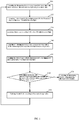
- FIG. 1 is a flow diagram of a control method of an illuminating device, provided by an embodiment of the present invention.
- An executive body of the control method may be a control circuit board mounted in the illuminating device.
- the control circuit board includes multiple elements, such as a micro control unit (MCU), and a sensor.
- the elements are electrically connected with a plurality of elements in the illuminating device, such as a light-emitting source, a power drive unit, and a possible power supply, by wired or wireless means.
- MCU micro control unit
- the control circuit board periodically starts the foregoing control method, so as to allow the irradiating light emitted by the light-emitting source of the illuminating device to be rapidly adjusted when the illuminated object is replaced.
- the foregoing control method comprises the following steps.
- S10 controlling the illuminating device to project initial detection light to the illuminated object, in which the color of the initial detection light is in an initial color.
- the light-emitting source of the illuminating device may be adopted to project the initial detection light.
- the irradiating light originally emitted by the light-emitting source of the illuminating device is turned off in advance, and then the projection of the detection light is switched on.
- auxiliary light-emitting source may also be disposed in the illuminating device. After the irradiating light originally emitted by the light-emitting source of the illuminating device is turned off, for the projection of the detection light through the auxiliary light-emitting source, the auxiliary light-emitting source is only required to be electrically connected with the drive unit and the power supply of the illuminating device. No further description will be given here.
- the initial detection light may be white light
- the color temperature of the white light may be 2,000K-30,000K and may also be within a smaller range of 2,500-25,000K.
- the white light has wider spectrum width and there is no interference of light of other colors currently, the reflected light of the illuminated object can be more accurately obtained.
- the initial detection light may also adopt light of other colors except the white light, as long as the light-emitting source can emit detection light of preset color by obtaining a PWM signal or a drive current value. No further description will be given here.
- a light-emitting diode may be used as the light source; light source paths formed by LED light sources of multiple colors are combined to form a mixed light array by using a RGB and RGBW light mixing mode; and the functions of dimming and color mixing can be achieved by using the drive unit to control the start and the brightness of the light source paths with the multiple colors.
- a sensor facing the illuminated object may be disposed on the illuminating device, and the sensor is adopted to acquire the initial reflected light on the basis of the initial detection light, and convert the initial reflected light into RGB electrical signals for embodying color.
- This technology is known by an ordinary skill in the art. No further description will be given here.
- the color of the initial reflected light embodies the color of the illuminated object.
- the target color obtained according to the color of the initial reflected light is relevant to the color of the illuminated object, so that the subsequently emitted target detection light of which the color is the target color can be gradually coordinated with the illuminated object in color.
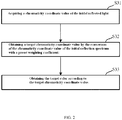
- the step S30 specifically includes the following steps:
- the chromaticity coordinate value corresponding to the RGB electrical signals may be obtained by the conversion of the RGB electrical signals of the initial reflected light acquired by the sensor.
- the technology is known by an ordinary skill in the art. No further description will be given here.
- control method of the illuminating device comprises two modes, namely a preset light sharing mode and a preset light filling mode.
- the irradiating light emitted by the illuminating device is adjusted to be basically consistent with the color of the illuminated object. For instance, when the color of the illuminated object is yellow, the irradiating light emitted by the illuminating device may be also adjusted to be yellow, so as to achieve the objective of positively embellishing the color of the illuminated object.
- the irradiating light emitted by the illuminating device is adjusted to be basically opposite to the color of the illuminated object. For instance, when the color of the illuminated object is yellow, the irradiating light emitted by the illuminating device may be adjusted to be other colors, such as purple, which is the complementary color of the yellow color, so as to achieve the objective of negatively embellishing the color of the illuminated object.
- the mutual coordination of the illuminated object and the irradiating light emitted by the illuminating device can be achieved by adjusting the color of the irradiating light emitted by the illuminating device, so that the illuminated object can be prominent.
- the technology is known by an ordinary skill in the art. No further description will be given here.
- the step S32 specifically includes the following steps:
- the target chromaticity coordinate value may be obtained by increasing the chromaticity coordinate value of the initial reflection spectrum with the preset weighting coefficient, so as to overcome the foregoing color attenuation.
- the target chromaticity coordinate value must be obtained by decreasing the chromaticity coordinate value of the initial reflection spectrum with the preset weighting coefficient.
- the foregoing preset weighting coefficient may be manually preset according to the degree of the preset light sharing mode, and the degree of the preset light filling mode, and the preset weighting coefficient required by the preset light sharing mode and the preset light filling mode may be set to be the same and may also be set to be different.
- RGB electrical signals for embodying the target color may be obtained by the conversion of the chromaticity coordinate value, which is opposite to the process of obtaining the chromaticity coordinate value corresponding to the RGB electrical signals by the conversion of the RGB electrical signals of the initial reflected light acquired by the sensor. No further description will be given here.
- S40 controlling the illuminating device to project target detection light to the illuminated object, in which the color of the target detection light is the target color.
- a target PWM signal, or a target drive current value is obtained according to the target color, and subsequently the illuminating device is controlled to project the target detection light to the illuminated object according to the target PWM signal, or the target drive current value.
- S50 acquiring the color of target reflected light generated by the illuminated object on the basis of the target detection light.
- a sensor facing the illuminated object may be disposed on the illuminating device, and the sensor is adopted to acquire the target reflected light on the basis of the target detection light, and convert the target reflected light into RGB electrical signals for embodying color.
- the technology is known by an ordinary skill in the art. No further description will be given here.
- step S60 determining whether the color difference between the initial reflected light and the target reflected light is within a preset color difference range, or not? If yes, executing the step S70, and if no, executing the step S80.
- whether the color difference between the initial reflected light and the target reflected light is within the preset color difference range is determined according to the difference of the chromaticity coordinate values of the initial reflected light and the target reflected light.
- the preset color difference range includes: the difference between the chromaticity coordinate value of the initial reflected light and the chromaticity coordinate value of the target reflected light is less than or equal to 0.001.
- the preset color difference range is not limited to the above range of 0.001.
- the specific value of the preset color difference range may be set as required. No further description will be given here.
- any irradiating light and the reflected light generated on the basis of the irradiating light are relevant to each other, and the range of the color of the irradiating light can be deducted by acquiring the color of the reflected light.
- the color of the irradiating light cannot be acquired, whether the color difference of the initial detection light and the target detection light is close, or not, cannot be calculated.
- the color difference between the initial reflected light and the target reflected light is within the preset color difference range, it can be apparently deducted that the color difference of the initial detection light and the target detection light is also very close.
- the target color is always close to the color of the irradiating light mostly coordinated with the color of the illuminated object.
- the color difference of the initial detection light and the target detection light is also close, it indicates that the color of the detection light does not change after the adjustment of the detection light for two adjacent times, then, it can be concluded that the detection light has been adjusted well. At this point, the color of the detection light is mostly coordinated with the color of the illuminated object.
- the initial color is needed to be updated according to the currently acquired target color, and the steps S10 to S60 are executed again; and the target detection light is updated through the step S30, until a conclusion is obtained in the step S60 that the color difference between the initial reflected light and the target reflected light is within the preset range.
- the required irradiating light may also be customized according to specific illumination requirement. For instance, irradiating light with preset color is provided for a certain garment, so as to obtain unique outstanding effect with distinctive personal features.
- the control method provided by the embodiment of the present invention may also be adopted to allow the irradiating light to be gradually close to the foregoing customized irradiating light, as long as the adjusting target of the irradiating light is only preset to be the customized irradiating light. No further description will be given here.
- the next detection light is obtained according to reflected light of the previous detection light.
- the illuminating device is controlled to project the next detection light to an illuminated object. In this way, no matter how the color of the illuminated object changes, or even the color change is very subtle, a detection light of which the color is mostly coordinated with the illuminated object can also be automatically obtained to illuminate the object continuously.
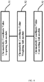
- FIG. 3 is a block diagram of a control system of an illuminating device, provided by an embodiment of the present invention.
- the control system may be operated by a control circuit board mounted in the illuminating device.
- the control circuit board is provided with multiple elements, such as a micro control unit (MCU), and a sensor.
- MCU micro control unit
- the elements are electrically connected with a plurality of elements in the illuminating device, such as a light-emitting source, a power drive unit, and a possible power supply, by wired or wireless means.
- the control circuit board periodically starts the foregoing control method, so as to allow the irradiating light emitted by the light-emitting source of the illuminating device to be rapidly adjusted when the illuminated object is replaced.
- the foregoing control system comprises the following modules.
- An emission control module 10 is comprised for controlling the illuminating device to project initial detection light to the illuminated object, in which the initial detection light is in an initial color.
- the light-emitting source of the illuminating device may be adopted to project the initial detection light.
- the irradiating light originally emitted by the light-emitting source of the illuminating device is turned off in advance, then the projection of the detection light is switched on.
- auxiliary light-emitting source may also be disposed in the illuminating device. After the irradiating light originally emitted by the light-emitting source of the illuminating device is turned off, for the projection of the detection light through the auxiliary light-emitting source, the auxiliary light-emitting source is only required to be electrically connected with the drive unit and the power supply of the illuminating device. No further description will be given here.
- the initial detection light may be white light
- the color temperature of the white light may be 2,000K-30,000K, or it may be within a smaller range of 2,500-25,000K.
- the white light has wider spectrum width and there is no interference of light of other colors currently, the reflected light of the illuminated object can be more accurately obtained.
- the initial detection light may also adopt light of other colors except the white light, as long as the light-emitting source can emit detection light of preset color by obtaining a PWM signal or a drive current value. No further description will be given here.
- a light-emitting diode may be used as the light source; light source paths formed by LED light sources of multiple colors are combined to form a mixed light array by utilization of RGB and RGBW light mixing mode; and the functions of dimming and color mixing can be achieved by adoption of the drive unit to control the start and the brightness of the light source paths with the multiple colors.
- a reflected light color acquiring module 20 is comprised for acquiring the color of initial reflected light generated by the illuminated object on the basis of the initial detection light.
- a sensor facing the illuminated object may be disposed on the illuminating device, and the sensor is adopted to acquire the initial reflected light on the basis of the initial detection light, and convert the initial reflected light into RGB electrical signals for embodying color.
- This technology is known by an ordinary skill in the art. No further description will be given here.
- a target color acquiring module 30 is comprised for acquiring target color according to the color of the initial reflected light.
- the color of the initial reflected light embodies the color of the illuminated object.
- the target color obtained according to the color of the initial reflected light is relevant to the color of the illuminated object, so that the subsequently emitted target detection light of which the color is the target color can be gradually coordinated with the illuminated object in color.
- the target color acquiring module 30 specifically includes the following modules.
- a chromaticity coordinate value acquiring sub-module 31 is included for acquiring a chromaticity coordinate value of the initial reflected light.
- the chromaticity coordinate value corresponding to the RGB electrical signals may be obtained by the conversion of the RGB electrical signals of the initial reflected light acquired by the sensor.
- the technology is known by an ordinary skill in the art. No further description will be given here.
- a chromaticity coordinate value weighting sub-module 32 is included for obtaining a target chromaticity coordinate value by the conversion of the chromaticity coordinate value of the initial reflection spectrum with a preset weighting coefficient.
- control system of the illuminating device comprises two modes, namely a preset light sharing mode and a preset light filling mode.
- the irradiating light emitted by the illuminating device is adjusted to be basically consistent with the color of the illuminated object. For instance, when the color of the illuminated object is yellow, the irradiating light emitted by the illuminating device may be also adjusted to be yellow, so as to achieve the objective of positively embellishing the color of the illuminated object.
- the irradiating light emitted by the illuminating device is adjusted to be basically opposite to the color of the illuminated object. For instance, when the color of the illuminated object is yellow, the irradiating light emitted by the illuminating device may be adjusted to be other colors, such as purple, which is the complementary color of yellow, so as to achieve the objective of negatively embellishing the color of the illuminated object.
- the mutual coordination of the illuminated object and the irradiating light emitted by the illuminating device can be achieved by adjusting the color of the irradiating light emitted by the illuminating device, so that the illuminated object can be prominent.
- This technology is known by an ordinary skill in the art. No further description will be given here.
- the chromaticity coordinate value weighting sub-module 32 is specifically used to:
- the target chromaticity coordinate value may be obtained by increasing the chromaticity coordinate value of the initial reflection spectrum with the preset weighting coefficient, so as to overcome the foregoing color attenuation.
- the target chromaticity coordinate value is needed to be obtained by decreasing the chromaticity coordinate value of the initial reflection spectrum with the preset weighting coefficient.
- the foregoing preset weighting coefficient may be manually preset according to the degree of the preset light sharing mode and the degree of the preset light filling mode, and the preset weighting coefficient required by the preset light sharing mode and the preset light filling mode may be set to be the same and may also be set to be different.
- a chromaticity coordinate value converting sub-module 33 is included for obtaining the target color according to the target chromaticity coordinate value.
- the RGB electrical signals for embodying the target color may be obtained by the conversion of the chromaticity coordinate value, which is opposite to the process of obtaining the chromaticity coordinate value corresponding to the RGB electrical signals by the conversion of the RGB electrical signals of the initial reflected light acquired by the sensor. No further description will be given here.
- the emission control module 10 is also used for controlling the illuminating device to project target detection light to the illuminated object, in which the target detection light is in the target color.
- a target PWM signal, or a target drive current value is obtained according to the target color, and subsequently the illuminating device is controlled to project the target detection light to the illuminated object according to the target PWM signal, or the target drive current value.
- the reflected light color acquiring module 20 is also used for acquiring the color of target reflected light generated by the illuminated object on the basis of the target detection light.
- a sensor facing the illuminated object may be disposed on the illuminating device, and the sensor is adopted to acquire the initial reflected light on the basis of the initial detection light, and convert the initial reflected light into RGB electrical signals for embodying color.
- This technology is known by an ordinary skill in the art. No further description will be given here.
- a color difference determining module 40 is included for determining whether the color difference between the initial reflected light and the target reflected light is within a preset color difference range.
- whether the color difference between the initial reflected light and the target reflected light is within the preset color difference range is determined according to the difference of the chromaticity coordinate values of the initial reflected light and the target reflected light.
- the preset color difference range includes: the difference between the chromaticity coordinate value of the initial reflected light and the chromaticity coordinate value of the target reflected light is less than or equal to 0.001.
- the preset color difference range is not limited to the above range of 0.001.
- the specific value of the preset color difference range may be set as required. No further description will be given here.
- the emission control module 10 is used for controlling the illuminating device to keep projecting the target detection light when the color difference between the initial reflected light and the target reflected light is within the preset color difference range.
- any irradiating light and the reflected light generated on the basis of the irradiating light are relevant to each other, and the range of the color of the irradiating light can be deducted by acquiring the color of the reflected light.
- the color of the irradiating light cannot be acquired, whether the color difference of the initial detection light and the target detection light is close, or not, cannot be calculated.
- the color difference between the initial reflected light and the target reflected light is within the preset color difference range, it can be apparently deducted that the color difference of the initial detection light and the target detection light is also very close.
- the target color is always close to the color of the irradiating light mostly coordinated with the color of the illuminated object.
- the color difference of the initial detection light and the target detection light is also close, it indicates that the color of the detection light does not change after the adjustment of the detection light for two adjacent times, then, it can be concluded that the detection light has been adjusted well. At this point, the color of the detection light is mostly coordinated with the color of the illuminated object.
- a color updating module 50 is included for updating the initial color according to the acquired target color when the color difference between the initial reflected light and the target reflected light is not within the preset color difference range.
- the initial color must be updated according to the currently acquired target color; the emission control module 10, the reflected light color acquiring module 20, the target color acquiring module 30 and the color difference determining module 40 execute the foregoing processes again; and the target detection light is updated through the target color acquiring module 30, until the conclusion that the color difference between the initial reflected light and the target reflected light is within the preset range is obtained in the color difference determining module 40.
- the reflected light color acquiring module 20, the target color acquiring module 30, the color difference determining module 40 and the color updating module 50 may be inter-communicated by wireless means, such as Bluetooth, WIFI, or ZigBee, or may be interconnected by wired means, such as a network cable, or a universal serial bus (USB).
- wireless means such as Bluetooth, WIFI, or ZigBee
- wired means such as a network cable, or a universal serial bus (USB).
- the reflected light color acquiring module 20 may be integrated into the illuminating device and may be separated from the illuminating device.
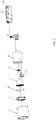
- the illuminating device comprises a light-emitting source 1, a reflecting shade 4, a transmitting shade 5, and a lamp body 6.
- the reflecting shade 4 covers the light-emitting source 1, and is expanded out towards the light exiting direction of the light-emitting source 1, so as to adjust or control the light-emitting direction of the light-emitting source 1.
- the transmitting cover 5 covers a light outlet of the reflecting shade 4 to form an optical control of final light emitting.
- a reflector holder 7 covers the transmitting shade 5 and is disposed on a light outlet of the lamp body 6, so as to fix components accommodated in the lamp body 6.
- the illuminating device further comprises a sensor module 3 fixed on a side of the lamp body 6, and the detection direction of the sensor module is consistent with the light-emitting direction of the light-emitting source 1 and, is roughly parallel and level to the light outlet of the reflecting shade 4 and the transmitting shade 5.
- the sensor module 3 corresponds to the reflected light color acquiring module 20 of the control system, and is used for acquiring accurate color information of the illuminated object in real time, which includes initial color and target color.
- the illuminating device further comprises a control circuit board 2 for periodically starting the foregoing control method, so as to allow that the irradiating light emitted by the light-emitting source 1 of the illuminating device to be rapidly adjusted when the illuminated object is replaced.
- a lamp body shade 8 is provided with an opening corresponding to the light-emitting direction of the reflecting shade 4 fixed on the reflector holder 7 and the detection direction of the sensor module 3, so as to provide convenience for light emitting and detection when simultaneously providing fixing, protection and aesthetic property by covering the outside of the lamp body 6 and the sensor module 3.
- a rotary support 9 is disposed at the rear of the lamp body 6 and connected with the control circuit board 2 and a power supply module 19.
- the sensor module 3 transmits data information of the illuminated object in the illumination direction of the light-emitting source 1, detected by the sensor module 3, to the control circuit board 2 through the rotary support 9; and the control circuit board 2 is adopted to feed back corresponding light effect adjustment instruction; and then the power supply module 19 controls the light-emitting source 1 to output corresponding light effect according to the corresponding light effect adjustment instruction.
- the light-emitting source 1 further includes: a light source unit, in which the light source unit preferably adopts an LED as a light source; light source paths formed by LED light sources of multiple colors are combined to form a mixed light array by utilization of RGB and RGBW light mixing mode; the functions of dimming and color mixing can be achieved by adoption of the power supply module 19 to control the start and the brightness of the light source paths of multiple colors; and hence the required light effect can be simulated and obtained.
- a light source unit in which the light source unit preferably adopts an LED as a light source
- light source paths formed by LED light sources of multiple colors are combined to form a mixed light array by utilization of RGB and RGBW light mixing mode
- the functions of dimming and color mixing can be achieved by adoption of the power supply module 19 to control the start and the brightness of the light source paths of multiple colors; and hence the required light effect can be simulated and obtained.
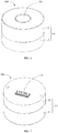
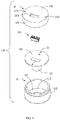
- FIGS. 6-9 and FIGS. 10-13 respectively illustrate the illuminating device provided with a reflected light color acquiring module 100 in different embodiments.
- the reflected light color acquiring module 100 includes: a housing 101, a PCB 102 accommodated in the housing 101, an optical lens 103 and a color detector 104 assembled on one side of the PCB 102, and a connector 105 assembled on the other side of the PCB 102.
- the housing 101 is made of insulating material(s) and includes a first cover body 11 and a second cover body 12 assembled together.
- the first cover body 11 includes a circular top wall 111 and a first side wall 112 extended from a side surface of the top wall 111.
- the top wall 111 of the first cover body 11 is provided with a first through hole 113 through which the lens 3 is exposed, and the first through hole 113 is circular.
- the second cover body 12 includes a bottom wall 121 and a second side wall 122 extended from a side surface of the bottom wall 121.
- the bottom wall 121 of the second cover body 12 is provided with a second through hole 123 through which the connector 105 is exposed, and two mounting holes 124 for the reflected light color acquiring module 100 to be rapidly mounted on the illuminating device (not shown), and the second through hole 123 is rectangular.
- the second cover body 12 is also provided with a plurality of supporting blocks 125 disposed on an interface of the bottom wall 121 and the second side wall 122, in which at least two supporting blocks 125 are respectively provided with screw holes.
- the first cover body 11 and the second cover body 12 can be fastened together by the threaded connection between the first side wall 112 and the second side wall 122.
- the PCB 102 is circular and is disposed on the plurality of supporting blocks 125 in the second cover body 12. Positioning holes 21 are formed on and run through the PCB 2.
- the PCB 102 and the second cover body 12 may be positioned by bolts (not shown).
- the optical lens 103 is cylindrical, and one end of the optical lens is accommodated in and extended to the first through hole 113, so that the optical lens can receive external light.
- the main functions of the optical lens 103 include: collecting light within a specific range according to different specifications of the selected optical lens; and adjusting the intensity of light reaching a surface of the color detector 104, in which the light travels through the optical lens.
- the color detector 104 may be a color sensor, or a spectral detector.
- the color detector 104 is fixed on the PCB 102 and disposed between the optical lens 103 and the PCB 102.
- the external light arrives at the surface of the color detector 104 after travelling through the optical lens 103.
- the color detector 104 collects the reflected light of the illuminated object and outputs proper electric parameters according to the reflected light; and color information is obtained after the signal processing of the obtained electrical parameters, namely surface color information of the illuminated object is obtained.
- the color information includes the relative intensity of R, G, and B components.
- the RGB color mode is a color standard in the industry, which obtains a variety of colors by the variation of three RGB channels and the superposition of each other.
- R, G, and B represent the colors of the three R, G, and B channels.
- the connector 105 may be bonded on the PCB 102 by surface mount technology (SMT).
- SMT surface mount technology
- the reflected light color acquiring module 100 in the preferred embodiment is assembled by the following steps.
- the specific steps include:
- the reflected light color acquiring module 100 is assembled.
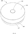
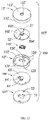
- a reflected light color acquiring module 100' includes: a housing 101', a PCB 102' accommodated in the housing 101', an optical lens 103' and a color detector 104' assembled on one side of the PCB 102', and a connector 105' assembled on the other side of the PCB 102'.
- the reflected light color acquiring module 100' further includes a first fastener 106' assembled on the housing 101'.
- the illuminating device includes a second fastener 107' cooperating with the first fastener 106' in a locking manner.
- the housing 101' is made of insulating material(s) and includes a first cover body 11' and a second cover body 12' assembled together.
- the first cover body 11' includes a circular top wall 111' and a first side wall 112' extended from a side surface of the top wall 111'.
- the top wall 111' of the first cover body 11' is provided with a first through hole 113' through which the optical lens 103' is exposed, and the first through hole 113' is circular.
- the lens 103' can be communicated with the outside via the first through hole 113'.
- the inner surface of the top wall 111' is also provided with a rectangular ring rib 114'.
- the rib 114' is disposed around the first through hole 113'.
- the second cover body 12' includes a bottom wall 121' and a second side wall 122' extended from a side surface of the bottom wall 121'.
- the bottom wall 121' of the second cover body 12' is provided with a second through hole 123' through which the connector 105' is exposed, and two mounting holes 124', and the second through hole 123' is rectangular.
- the connector 105' may be communicated with the outside of the housing 101' via the second through hole 123'.
- the second cover body 12' is also provided with a plurality of supporting blocks 125' disposed on an interface of the bottom wall 121' and the second side wall 122', in which at least two supporting blocks 125' are respectively provided with screw holes 126'.
- the first cover body 11' and the second cover body 12' are fastened together by the threaded connection between the first side wall 112' and the second side wall 122'.
- the PCB 102' is circular and is disposed on the plurality of supporting blocks 125' in the second cover body 12'. Positioning holes 21' are formed on and run through the PCB 102'.
- the PCB 102' includes a positioning block 22'. The PCB 102' and the second cover body 12' can be positioned by bolts (not shown).
- the positioning block 22' is accommodated in an accommodating space (not marked) formed by the rectangular ring rib 114', so as to position the PCB 102' and the first cover body 11'.
- the optical lens 103' is cylindrical and is disposed on the positioning block 22' of the PCB 102'.
- the optical lens 103' is accommodated in and extended to the first through hole 113'.
- the main functions of the optical lens 103' include: collecting light within a specific range according to different specifications of the selected optical lens 103', for instance, collecting ambient light, or light emitted by an object; and adjusting the intensity of light travelling through the optical lens 103' and reaching a surface of the color detector 104'.
- the color detector 104' can be a color sensor, or a spectral detector.
- the color detector 104' is fixed on the PCB 102' and disposed between the optical lens 103' and the PCB 102'.
- the external light arrives at the surface of the color detector 104' after travelling through the optical lens 103'.
- the color detector 104' collects the reflected light of the illuminated object and outputs proper electric parameters according to the reflected light; and color information is obtained after the signal processing of the obtained electrical parameters, namely surface color information of the illuminated object is obtained.
- the color information includes the relative intensity of R, G, and B components, namely chromaticity coordinate points of the colors.
- the RGB color mode is a color standard in the industry, which obtains a variety of colors by the variation of three RGB channels and the superposition of each other.
- R, G, and B represent the colors of the three RGB channels.
- the connector 105' can be bonded on the PCB 102' by surface mount technology (SMT).
- SMT surface mount technology
- the first fastener 106' is circular and is provided with a through hole 61', a recess 64' communicated with the through hole 61', and two screw holes 63'.
- the through hole 61' is disposed in the center of the first fastener 106', and the recess 64' is disposed on a surface contacting the second cover body 12'.
- the other surface of the first fastener 106' is provided with a tubular positioning part 62', and a locking block 621' is disposed on the positioning part 62'.
- the first fastener 106' can be fastened on the second cover body 12' by bolts (not marked).
- the reflected light color acquiring module 100' in the preferred embodiment of the present invention is assembled by the following steps, and the specific steps include:
- the reflected light color acquiring module 100' is assembled.
- the reflected light color acquiring module 100' is provided with a fastener, namely the first fastener 106', the reflected light color acquiring module 100' can be rapidly mounted on the illuminating device.
- a second fastener 107' on the illuminating device provided by the preferred embodiment is circular and is provided with a locking hole 71' for accommodating the positioning part 62' on the first fastener 106', and three stop blocks 72' disposed in the locking hole 71'.
- Each stop block 72' is provided with a depressed part 721' and ribs 722' and 723' disposed on two sides of the depressed part 721'. The height of the rib 723' is less than the height of the rib 722'.
- the positioning part 62' of the second fastener 107' is rotated for a certain angle after being accommodated into the locking hole 71', so that the locking block 621' can be accommodated into the depressed part 721' after passing over the lower rib 723' on the stop block 72'. Due to the limitation of the ribs 722' and 723', the second fastener 107' is stably fixed on the first fastener 106'. The second fastener 107' is mounted on the illuminating device. The through hole 61' and the locking hole 71' allow a connecting line to run through.
- the reflected light color acquiring module 100' and the illuminating device can be rapidly connected by the fastening cooperation of the first fastener 106' and the second fastener 107'.
- the required irradiating light may also be customized according to specific illumination requirement, for instance, irradiating light with a preset color is provided for certain garment, so as to obtain unique outstanding effect with distinctive personal features.
- the control system provided by the embodiment of the present invention may still be adopted to allow the irradiating light to be gradually close to the foregoing customized irradiating light, as long as the adjusting target of the irradiating light is preset only to be the customized irradiating light. No further description will be given here.
- the next detection light is obtained according to reflected light of the previous detection light.
- the illuminating device is controlled to project the next detection light to an illuminated object. In this way, no matter how the color of the illuminated object changes, or even the color change is very subtle, a detection light of which the color is mostly coordinated with the illuminated object can also be automatically obtained to illuminate the object continuously.
Landscapes
- Circuit Arrangement For Electric Light Sources In General (AREA)
Applications Claiming Priority (9)
| Application Number | Priority Date | Filing Date | Title |
|---|---|---|---|
| CN201510310386.0A CN104913273A (zh) | 2015-06-08 | 2015-06-08 | 颜色识别模组、照明装置及其控制方法 |
| CN201520394488.0U CN204943358U (zh) | 2015-06-08 | 2015-06-08 | 颜色识别模组、照明装置 |
| CN201510310390.7A CN104913275A (zh) | 2015-06-08 | 2015-06-08 | 颜色识别模组、照明装置及其的控制方法 |
| CN201520390836.7U CN204704776U (zh) | 2015-06-08 | 2015-06-08 | 颜色识别模组、照明装置 |
| CN201520389892 | 2015-06-08 | ||
| CN201510309709.4A CN106287404A (zh) | 2015-06-08 | 2015-06-08 | 一种自适应射灯及控制方法 |
| CN201510310418.7A CN105101535B (zh) | 2015-06-08 | 2015-06-08 | 照明装置及其控制方法和控制系统 |
| CN201520390860.0U CN205142580U (zh) | 2015-06-08 | 2015-06-08 | 照明装置及其控制系统 |
| PCT/CN2016/085042 WO2016197903A1 (zh) | 2015-06-08 | 2016-06-07 | 照明装置及其控制方法和控制系统 |
Publications (3)
| Publication Number | Publication Date |
|---|---|
| EP3220723A1 true EP3220723A1 (de) | 2017-09-20 |
| EP3220723A4 EP3220723A4 (de) | 2018-03-14 |
| EP3220723B1 EP3220723B1 (de) | 2021-07-07 |
Family
ID=57503221
Family Applications (1)
| Application Number | Title | Priority Date | Filing Date |
|---|---|---|---|
| EP16806801.3A Active EP3220723B1 (de) | 2015-06-08 | 2016-06-07 | Beleuchtungsvorrichtung sowie steuerungsverfahren und steuerungssystem dafür |
Country Status (4)
| Country | Link |
|---|---|
| US (1) | US10251239B2 (de) |
| EP (1) | EP3220723B1 (de) |
| DE (1) | DE202016008521U1 (de) |
| WO (1) | WO2016197903A1 (de) |
Families Citing this family (6)
| Publication number | Priority date | Publication date | Assignee | Title |
|---|---|---|---|---|
| WO2019246431A1 (en) * | 2018-06-22 | 2019-12-26 | Lumileds Llc | Lighting system with integrated sensor |
| US10582589B2 (en) | 2018-06-22 | 2020-03-03 | Lumileds Llc | Lighting system with integrated sensor |
| US20200044468A1 (en) * | 2018-07-31 | 2020-02-06 | Ling Yung LIN | Mobile power supply module with light source |
| CN111065183B (zh) * | 2019-12-31 | 2023-07-25 | 广东晶科电子股份有限公司 | 一种用于控制led台灯的光照强度的方法及系统 |
| CN114494836B (zh) * | 2022-04-02 | 2022-07-01 | 蜂联智能(深圳)有限公司 | 一种基于区域环境的光照智能调试系统 |
| CN116939919A (zh) * | 2023-07-27 | 2023-10-24 | 深蓝汽车科技有限公司 | 车辆内饰光源色坐标标定方法、装置、电子设备及介质 |
Family Cites Families (39)
| Publication number | Priority date | Publication date | Assignee | Title |
|---|---|---|---|---|
| US8403523B2 (en) | 2003-03-18 | 2013-03-26 | Electronic Theatre Controls, Inc. | Methods, luminaires and systems for matching a composite light spectrum to a target light spectrum |
| US20040218387A1 (en) | 2003-03-18 | 2004-11-04 | Robert Gerlach | LED lighting arrays, fixtures and systems and method for determining human color perception |
| MXPA05011291A (es) | 2003-04-25 | 2006-05-25 | Visioneered Image Systems Inc | Visualizador/fuente de iluminacion de led con capacidad de monitoreo de brillo de led individual y metodo de calibracion. |
| JP4516467B2 (ja) | 2005-03-29 | 2010-08-04 | シャープ株式会社 | 面照明装置及びそれを備えた液晶表示装置 |
| CN100544532C (zh) | 2005-04-28 | 2009-09-23 | 皇家飞利浦电子股份有限公司 | 改进的发光系统 |
| JP4487888B2 (ja) | 2005-09-09 | 2010-06-23 | パナソニック電工株式会社 | Led照明器具 |
| ATE443427T1 (de) | 2005-10-13 | 2009-10-15 | Koninkl Philips Electronics Nv | Verfahren und system zur beleuchtung mit variablen farben |
| ATE525855T1 (de) | 2007-01-03 | 2011-10-15 | Koninkl Philips Electronics Nv | Anzeigevorrichtung mit umgebungslicht |
| US7773224B2 (en) * | 2007-09-28 | 2010-08-10 | Motorola, Inc. | Spectrum verification imaging system and method |
| CN201340482Y (zh) | 2008-01-11 | 2009-11-04 | 马佳贵 | 隐形技术装置 |
| US20130307419A1 (en) * | 2012-05-18 | 2013-11-21 | Dmitri Simonian | Lighting system with sensor feedback |
| US9509525B2 (en) | 2008-09-05 | 2016-11-29 | Ketra, Inc. | Intelligent illumination device |
| KR20110110214A (ko) | 2008-12-23 | 2011-10-06 | 코닌클리케 필립스 일렉트로닉스 엔.브이. | 디스플레이 디바이스를 위한 주변 조명 시스템 및 이러한 주변 조명 시스템을 동작하는 방법 |
| US20100201275A1 (en) | 2009-02-06 | 2010-08-12 | Cok Ronald S | Light sensing in display device |
| JP5507148B2 (ja) * | 2009-08-10 | 2014-05-28 | スタンレー電気株式会社 | 照明装置 |
| JP4975797B2 (ja) | 2009-10-14 | 2012-07-11 | シャープ株式会社 | 照明装置、車両用灯具および車両 |
| CN102062638A (zh) * | 2009-11-17 | 2011-05-18 | 吴冬雨 | 一种单色物体识别装置 |
| US9295134B2 (en) * | 2009-12-09 | 2016-03-22 | Koninklijke Philips N.V. | Light system for emphasizing objects |
| JP5174835B2 (ja) | 2010-01-08 | 2013-04-03 | シャープ株式会社 | Led電球 |
| US8723426B2 (en) | 2010-07-15 | 2014-05-13 | Prism Projection, Inc. | Systems and methods for sampling light produced from an LED array |
| KR20130143102A (ko) | 2011-01-03 | 2013-12-30 | 푼다시오 인스티튜트 데 레세르카 데 레네르기아 데 카탈루냐 | 주변광 스펙트럼을 얻고 발광을 수정하기 위한 광전자 디바이스,시스템 및 방법 |
| US8890435B2 (en) | 2011-03-11 | 2014-11-18 | Ilumi Solutions, Inc. | Wireless lighting control system |
| KR20120139390A (ko) | 2011-06-17 | 2012-12-27 | 삼성전자주식회사 | 이미지 촬영을 위한 광원 제어 장치, 시스템 및 방법 |
| EP2878173B8 (de) | 2012-07-27 | 2019-04-10 | Signify Holding B.V. | Farbbetonung und konservierung von objekten mittels reflektionsspektren |
| CN102858072B (zh) * | 2012-09-28 | 2014-12-17 | 北京半导体照明科技促进中心 | 照明控制方法及系统 |
| CN103857096A (zh) * | 2012-11-28 | 2014-06-11 | 胡能忠 | 最佳视觉照明装置及方法 |
| CN104344248A (zh) | 2013-08-05 | 2015-02-11 | 上海广茂达光艺科技股份有限公司 | 一种智能混光系统和方法 |
| CN103470992B (zh) | 2013-09-27 | 2016-03-23 | 中国科学院半导体研究所 | 一种投影式照明系统 |
| CN104100924B (zh) | 2013-11-26 | 2016-04-13 | 深圳市华星光电技术有限公司 | 背光模组及使用该背光模组的背光系统 |
| CN104486861B (zh) * | 2014-11-12 | 2017-02-22 | 常州市武进区半导体照明应用技术研究院 | 灯光控制方法、装置及系统 |
| US9992842B2 (en) * | 2014-12-01 | 2018-06-05 | Industrial Technology Research Institute | Illumination system and method for developing target visual perception of an object |
| CN105101535B (zh) * | 2015-06-08 | 2018-02-09 | 欧普照明股份有限公司 | 照明装置及其控制方法和控制系统 |
| CN204943358U (zh) * | 2015-06-08 | 2016-01-06 | 欧普照明股份有限公司 | 颜色识别模组、照明装置 |
| CN104913275A (zh) * | 2015-06-08 | 2015-09-16 | 欧普照明股份有限公司 | 颜色识别模组、照明装置及其的控制方法 |
| CN104918372B (zh) | 2015-06-08 | 2017-09-29 | 欧普照明股份有限公司 | 照明装置及其控制方法和控制系统 |
| CN204929316U (zh) * | 2015-06-08 | 2015-12-30 | 欧普照明股份有限公司 | 照明装置及其控制系统 |
| CN104913273A (zh) | 2015-06-08 | 2015-09-16 | 欧普照明股份有限公司 | 颜色识别模组、照明装置及其控制方法 |
| CN205142580U (zh) | 2015-06-08 | 2016-04-06 | 欧普照明股份有限公司 | 照明装置及其控制系统 |
| CN204704776U (zh) * | 2015-06-08 | 2015-10-14 | 欧普照明股份有限公司 | 颜色识别模组、照明装置 |
-
2016
- 2016-06-07 DE DE202016008521.3U patent/DE202016008521U1/de active Active
- 2016-06-07 WO PCT/CN2016/085042 patent/WO2016197903A1/zh not_active Ceased
- 2016-06-07 EP EP16806801.3A patent/EP3220723B1/de active Active
-
2017
- 2017-08-18 US US15/680,982 patent/US10251239B2/en active Active
Also Published As
| Publication number | Publication date |
|---|---|
| US10251239B2 (en) | 2019-04-02 |
| EP3220723B1 (de) | 2021-07-07 |
| WO2016197903A1 (zh) | 2016-12-15 |
| EP3220723A4 (de) | 2018-03-14 |
| US20170347425A1 (en) | 2017-11-30 |
| DE202016008521U1 (de) | 2018-05-17 |
Similar Documents
| Publication | Publication Date | Title |
|---|---|---|
| US10251239B2 (en) | Illuminating device, control method thereof and control system thereof | |
| CN103503577A (zh) | Led照明系统 | |
| US10285244B2 (en) | Illuminating device, control method thereof and control system thereof | |
| CN104913273A (zh) | 颜色识别模组、照明装置及其控制方法 | |
| JP6712771B2 (ja) | 照明システム及びそれを備えた移動体 | |
| EP2575413A2 (de) | Beleuchtungssystem und Steuerverfahren dafür | |
| KR20090109323A (ko) | 엘이디 제어를 이용한 감성조명 시스템 | |
| JP6799804B2 (ja) | 照明装置及びそれを備えた照明システム、移動体 | |
| EP3562270B1 (de) | Kalibrierung von treibern einer lichtquelle | |
| CN204943358U (zh) | 颜色识别模组、照明装置 | |
| JP6617882B2 (ja) | 照明器具、照明システム及び照明システムの設定方法 | |
| CN105101535B (zh) | 照明装置及其控制方法和控制系统 | |
| CN204929316U (zh) | 照明装置及其控制系统 | |
| CN204704776U (zh) | 颜色识别模组、照明装置 | |
| CN104913275A (zh) | 颜色识别模组、照明装置及其的控制方法 | |
| CN107690551A (zh) | 具有模块化光源和电子可调光束分布的固态泛光灯 | |
| CN104918371A (zh) | 照明装置及其控制方法 | |
| US20250071875A1 (en) | Beam angle matching for multi-color fixtures | |
| CA2988612C (en) | Wall grazer light fixture | |
| EP2568772A2 (de) | Beleuchtnungsanordnung und Steuerungsverfahren dafür | |
| US10746362B1 (en) | Wall wash luminaire | |
| JP2019009056A (ja) | 照明装置 | |
| CN204810604U (zh) | 照明装置 | |
| JP7320753B2 (ja) | 制御システム | |
| JP2007173120A (ja) | 照明装置及びこれを含む照明器具 |
Legal Events
| Date | Code | Title | Description |
|---|---|---|---|
| REG | Reference to a national code |
Ref country code: DE Ref legal event code: R138 Ref document number: 202016008521 Country of ref document: DE Free format text: GERMAN DOCUMENT NUMBER IS 602016060389 |
|
| STAA | Information on the status of an ep patent application or granted ep patent |
Free format text: STATUS: THE INTERNATIONAL PUBLICATION HAS BEEN MADE |
|
| PUAI | Public reference made under article 153(3) epc to a published international application that has entered the european phase |
Free format text: ORIGINAL CODE: 0009012 |
|
| STAA | Information on the status of an ep patent application or granted ep patent |
Free format text: STATUS: REQUEST FOR EXAMINATION WAS MADE |
|
| 17P | Request for examination filed |
Effective date: 20170612 |
|
| AK | Designated contracting states |
Kind code of ref document: A1 Designated state(s): AL AT BE BG CH CY CZ DE DK EE ES FI FR GB GR HR HU IE IS IT LI LT LU LV MC MK MT NL NO PL PT RO RS SE SI SK SM TR |
|
| AX | Request for extension of the european patent |
Extension state: BA ME |
|
| A4 | Supplementary search report drawn up and despatched |
Effective date: 20180209 |
|
| RIC1 | Information provided on ipc code assigned before grant |
Ipc: H05B 37/02 20060101AFI20180205BHEP Ipc: H05B 33/08 20060101ALI20180205BHEP |
|
| DAV | Request for validation of the european patent (deleted) | ||
| DAX | Request for extension of the european patent (deleted) | ||
| STAA | Information on the status of an ep patent application or granted ep patent |
Free format text: STATUS: EXAMINATION IS IN PROGRESS |
|
| 17Q | First examination report despatched |
Effective date: 20190726 |
|
| REG | Reference to a national code |
Ref country code: DE Ref legal event code: R079 Ref document number: 602016060389 Country of ref document: DE Free format text: PREVIOUS MAIN CLASS: H05B0037020000 Ipc: H05B0045220000 |
|
| RIC1 | Information provided on ipc code assigned before grant |
Ipc: H05B 45/22 20200101AFI20201210BHEP |
|
| GRAP | Despatch of communication of intention to grant a patent |
Free format text: ORIGINAL CODE: EPIDOSNIGR1 |
|
| STAA | Information on the status of an ep patent application or granted ep patent |
Free format text: STATUS: GRANT OF PATENT IS INTENDED |
|
| INTG | Intention to grant announced |
Effective date: 20210118 |
|
| GRAS | Grant fee paid |
Free format text: ORIGINAL CODE: EPIDOSNIGR3 |
|
| GRAA | (expected) grant |
Free format text: ORIGINAL CODE: 0009210 |
|
| STAA | Information on the status of an ep patent application or granted ep patent |
Free format text: STATUS: THE PATENT HAS BEEN GRANTED |
|
| AK | Designated contracting states |
Kind code of ref document: B1 Designated state(s): AL AT BE BG CH CY CZ DE DK EE ES FI FR GB GR HR HU IE IS IT LI LT LU LV MC MK MT NL NO PL PT RO RS SE SI SK SM TR |
|
| REG | Reference to a national code |
Ref country code: GB Ref legal event code: FG4D |
|
| REG | Reference to a national code |
Ref country code: AT Ref legal event code: REF Ref document number: 1409903 Country of ref document: AT Kind code of ref document: T Effective date: 20210715 |
|
| REG | Reference to a national code |
Ref country code: DE Ref legal event code: R096 Ref document number: 602016060389 Country of ref document: DE |
|
| REG | Reference to a national code |
Ref country code: IE Ref legal event code: FG4D |
|
| REG | Reference to a national code |
Ref country code: NL Ref legal event code: FP |
|
| REG | Reference to a national code |
Ref country code: LT Ref legal event code: MG9D |
|
| REG | Reference to a national code |
Ref country code: AT Ref legal event code: MK05 Ref document number: 1409903 Country of ref document: AT Kind code of ref document: T Effective date: 20210707 |
|
| PG25 | Lapsed in a contracting state [announced via postgrant information from national office to epo] |
Ref country code: RS Free format text: LAPSE BECAUSE OF FAILURE TO SUBMIT A TRANSLATION OF THE DESCRIPTION OR TO PAY THE FEE WITHIN THE PRESCRIBED TIME-LIMIT Effective date: 20210707 Ref country code: SE Free format text: LAPSE BECAUSE OF FAILURE TO SUBMIT A TRANSLATION OF THE DESCRIPTION OR TO PAY THE FEE WITHIN THE PRESCRIBED TIME-LIMIT Effective date: 20210707 Ref country code: LT Free format text: LAPSE BECAUSE OF FAILURE TO SUBMIT A TRANSLATION OF THE DESCRIPTION OR TO PAY THE FEE WITHIN THE PRESCRIBED TIME-LIMIT Effective date: 20210707 Ref country code: AT Free format text: LAPSE BECAUSE OF FAILURE TO SUBMIT A TRANSLATION OF THE DESCRIPTION OR TO PAY THE FEE WITHIN THE PRESCRIBED TIME-LIMIT Effective date: 20210707 Ref country code: BG Free format text: LAPSE BECAUSE OF FAILURE TO SUBMIT A TRANSLATION OF THE DESCRIPTION OR TO PAY THE FEE WITHIN THE PRESCRIBED TIME-LIMIT Effective date: 20211007 Ref country code: FI Free format text: LAPSE BECAUSE OF FAILURE TO SUBMIT A TRANSLATION OF THE DESCRIPTION OR TO PAY THE FEE WITHIN THE PRESCRIBED TIME-LIMIT Effective date: 20210707 Ref country code: ES Free format text: LAPSE BECAUSE OF FAILURE TO SUBMIT A TRANSLATION OF THE DESCRIPTION OR TO PAY THE FEE WITHIN THE PRESCRIBED TIME-LIMIT Effective date: 20210707 Ref country code: HR Free format text: LAPSE BECAUSE OF FAILURE TO SUBMIT A TRANSLATION OF THE DESCRIPTION OR TO PAY THE FEE WITHIN THE PRESCRIBED TIME-LIMIT Effective date: 20210707 Ref country code: NO Free format text: LAPSE BECAUSE OF FAILURE TO SUBMIT A TRANSLATION OF THE DESCRIPTION OR TO PAY THE FEE WITHIN THE PRESCRIBED TIME-LIMIT Effective date: 20211007 Ref country code: PT Free format text: LAPSE BECAUSE OF FAILURE TO SUBMIT A TRANSLATION OF THE DESCRIPTION OR TO PAY THE FEE WITHIN THE PRESCRIBED TIME-LIMIT Effective date: 20211108 |
|
| PG25 | Lapsed in a contracting state [announced via postgrant information from national office to epo] |
Ref country code: PL Free format text: LAPSE BECAUSE OF FAILURE TO SUBMIT A TRANSLATION OF THE DESCRIPTION OR TO PAY THE FEE WITHIN THE PRESCRIBED TIME-LIMIT Effective date: 20210707 Ref country code: LV Free format text: LAPSE BECAUSE OF FAILURE TO SUBMIT A TRANSLATION OF THE DESCRIPTION OR TO PAY THE FEE WITHIN THE PRESCRIBED TIME-LIMIT Effective date: 20210707 Ref country code: GR Free format text: LAPSE BECAUSE OF FAILURE TO SUBMIT A TRANSLATION OF THE DESCRIPTION OR TO PAY THE FEE WITHIN THE PRESCRIBED TIME-LIMIT Effective date: 20211008 |
|
| REG | Reference to a national code |
Ref country code: DE Ref legal event code: R097 Ref document number: 602016060389 Country of ref document: DE |
|
| PG25 | Lapsed in a contracting state [announced via postgrant information from national office to epo] |
Ref country code: DK Free format text: LAPSE BECAUSE OF FAILURE TO SUBMIT A TRANSLATION OF THE DESCRIPTION OR TO PAY THE FEE WITHIN THE PRESCRIBED TIME-LIMIT Effective date: 20210707 |
|
| PLBE | No opposition filed within time limit |
Free format text: ORIGINAL CODE: 0009261 |
|
| STAA | Information on the status of an ep patent application or granted ep patent |
Free format text: STATUS: NO OPPOSITION FILED WITHIN TIME LIMIT |
|
| PG25 | Lapsed in a contracting state [announced via postgrant information from national office to epo] |
Ref country code: SM Free format text: LAPSE BECAUSE OF FAILURE TO SUBMIT A TRANSLATION OF THE DESCRIPTION OR TO PAY THE FEE WITHIN THE PRESCRIBED TIME-LIMIT Effective date: 20210707 Ref country code: SK Free format text: LAPSE BECAUSE OF FAILURE TO SUBMIT A TRANSLATION OF THE DESCRIPTION OR TO PAY THE FEE WITHIN THE PRESCRIBED TIME-LIMIT Effective date: 20210707 Ref country code: RO Free format text: LAPSE BECAUSE OF FAILURE TO SUBMIT A TRANSLATION OF THE DESCRIPTION OR TO PAY THE FEE WITHIN THE PRESCRIBED TIME-LIMIT Effective date: 20210707 Ref country code: EE Free format text: LAPSE BECAUSE OF FAILURE TO SUBMIT A TRANSLATION OF THE DESCRIPTION OR TO PAY THE FEE WITHIN THE PRESCRIBED TIME-LIMIT Effective date: 20210707 Ref country code: CZ Free format text: LAPSE BECAUSE OF FAILURE TO SUBMIT A TRANSLATION OF THE DESCRIPTION OR TO PAY THE FEE WITHIN THE PRESCRIBED TIME-LIMIT Effective date: 20210707 Ref country code: AL Free format text: LAPSE BECAUSE OF FAILURE TO SUBMIT A TRANSLATION OF THE DESCRIPTION OR TO PAY THE FEE WITHIN THE PRESCRIBED TIME-LIMIT Effective date: 20210707 |
|
| 26N | No opposition filed |
Effective date: 20220408 |
|
| PG25 | Lapsed in a contracting state [announced via postgrant information from national office to epo] |
Ref country code: IT Free format text: LAPSE BECAUSE OF FAILURE TO SUBMIT A TRANSLATION OF THE DESCRIPTION OR TO PAY THE FEE WITHIN THE PRESCRIBED TIME-LIMIT Effective date: 20210707 |
|
| PG25 | Lapsed in a contracting state [announced via postgrant information from national office to epo] |
Ref country code: MC Free format text: LAPSE BECAUSE OF FAILURE TO SUBMIT A TRANSLATION OF THE DESCRIPTION OR TO PAY THE FEE WITHIN THE PRESCRIBED TIME-LIMIT Effective date: 20210707 |
|
| REG | Reference to a national code |
Ref country code: CH Ref legal event code: PL |
|
| PG25 | Lapsed in a contracting state [announced via postgrant information from national office to epo] |
Ref country code: LU Free format text: LAPSE BECAUSE OF NON-PAYMENT OF DUE FEES Effective date: 20220607 Ref country code: LI Free format text: LAPSE BECAUSE OF NON-PAYMENT OF DUE FEES Effective date: 20220630 Ref country code: IE Free format text: LAPSE BECAUSE OF NON-PAYMENT OF DUE FEES Effective date: 20220607 Ref country code: CH Free format text: LAPSE BECAUSE OF NON-PAYMENT OF DUE FEES Effective date: 20220630 |
|
| PG25 | Lapsed in a contracting state [announced via postgrant information from national office to epo] |
Ref country code: HU Free format text: LAPSE BECAUSE OF FAILURE TO SUBMIT A TRANSLATION OF THE DESCRIPTION OR TO PAY THE FEE WITHIN THE PRESCRIBED TIME-LIMIT; INVALID AB INITIO Effective date: 20160607 |
|
| PG25 | Lapsed in a contracting state [announced via postgrant information from national office to epo] |
Ref country code: MK Free format text: LAPSE BECAUSE OF FAILURE TO SUBMIT A TRANSLATION OF THE DESCRIPTION OR TO PAY THE FEE WITHIN THE PRESCRIBED TIME-LIMIT Effective date: 20210707 Ref country code: CY Free format text: LAPSE BECAUSE OF FAILURE TO SUBMIT A TRANSLATION OF THE DESCRIPTION OR TO PAY THE FEE WITHIN THE PRESCRIBED TIME-LIMIT Effective date: 20210707 |
|
| PGFP | Annual fee paid to national office [announced via postgrant information from national office to epo] |
Ref country code: FR Payment date: 20240624 Year of fee payment: 9 |
|
| PGFP | Annual fee paid to national office [announced via postgrant information from national office to epo] |
Ref country code: BE Payment date: 20240620 Year of fee payment: 9 |
|
| PG25 | Lapsed in a contracting state [announced via postgrant information from national office to epo] |
Ref country code: MT Free format text: LAPSE BECAUSE OF FAILURE TO SUBMIT A TRANSLATION OF THE DESCRIPTION OR TO PAY THE FEE WITHIN THE PRESCRIBED TIME-LIMIT Effective date: 20210707 |
|
| PGFP | Annual fee paid to national office [announced via postgrant information from national office to epo] |
Ref country code: NL Payment date: 20250528 Year of fee payment: 10 |
|
| PGFP | Annual fee paid to national office [announced via postgrant information from national office to epo] |
Ref country code: DE Payment date: 20250617 Year of fee payment: 10 |
|
| PGFP | Annual fee paid to national office [announced via postgrant information from national office to epo] |
Ref country code: GB Payment date: 20250625 Year of fee payment: 10 |
|
| PG25 | Lapsed in a contracting state [announced via postgrant information from national office to epo] |
Ref country code: TR Free format text: LAPSE BECAUSE OF FAILURE TO SUBMIT A TRANSLATION OF THE DESCRIPTION OR TO PAY THE FEE WITHIN THE PRESCRIBED TIME-LIMIT Effective date: 20210707 |
|
| REG | Reference to a national code |
Ref country code: BE Ref legal event code: MM Effective date: 20250630 |
|
| PG25 | Lapsed in a contracting state [announced via postgrant information from national office to epo] |
Ref country code: BE Free format text: LAPSE BECAUSE OF NON-PAYMENT OF DUE FEES Effective date: 20250630 |
|
| PG25 | Lapsed in a contracting state [announced via postgrant information from national office to epo] |
Ref country code: FR Free format text: LAPSE BECAUSE OF NON-PAYMENT OF DUE FEES Effective date: 20250630 |