EP3220730A1 - Dispositif de commande pour dispositif de fixation de composant électronique, et dispositif de saisie de données pour dispositif de commande - Google Patents
Dispositif de commande pour dispositif de fixation de composant électronique, et dispositif de saisie de données pour dispositif de commande Download PDFInfo
- Publication number
- EP3220730A1 EP3220730A1 EP14905944.6A EP14905944A EP3220730A1 EP 3220730 A1 EP3220730 A1 EP 3220730A1 EP 14905944 A EP14905944 A EP 14905944A EP 3220730 A1 EP3220730 A1 EP 3220730A1
- Authority
- EP
- European Patent Office
- Prior art keywords
- divided
- board
- group
- mounting
- control device
- Prior art date
- Legal status (The legal status is an assumption and is not a legal conclusion. Google has not performed a legal analysis and makes no representation as to the accuracy of the status listed.)
- Granted
Links
Images


Classifications
-
- H—ELECTRICITY
- H05—ELECTRIC TECHNIQUES NOT OTHERWISE PROVIDED FOR
- H05K—PRINTED CIRCUITS; CASINGS OR CONSTRUCTIONAL DETAILS OF ELECTRIC APPARATUS; MANUFACTURE OF ASSEMBLAGES OF ELECTRICAL COMPONENTS
- H05K13/00—Apparatus or processes specially adapted for manufacturing or adjusting assemblages of electric components
- H05K13/08—Monitoring manufacture of assemblages
- H05K13/085—Production planning, e.g. of allocation of products to machines, of mounting sequences at machine or facility level
- H05K13/0853—Determination of transport trajectories inside mounting machines
-
- H—ELECTRICITY
- H05—ELECTRIC TECHNIQUES NOT OTHERWISE PROVIDED FOR
- H05K—PRINTED CIRCUITS; CASINGS OR CONSTRUCTIONAL DETAILS OF ELECTRIC APPARATUS; MANUFACTURE OF ASSEMBLAGES OF ELECTRICAL COMPONENTS
- H05K13/00—Apparatus or processes specially adapted for manufacturing or adjusting assemblages of electric components
- H05K13/08—Monitoring manufacture of assemblages
- H05K13/0882—Control systems for mounting machines or assembly lines, e.g. centralized control, remote links, programming of apparatus and processes as such
-
- H—ELECTRICITY
- H05—ELECTRIC TECHNIQUES NOT OTHERWISE PROVIDED FOR
- H05K—PRINTED CIRCUITS; CASINGS OR CONSTRUCTIONAL DETAILS OF ELECTRIC APPARATUS; MANUFACTURE OF ASSEMBLAGES OF ELECTRICAL COMPONENTS
- H05K13/00—Apparatus or processes specially adapted for manufacturing or adjusting assemblages of electric components
- H05K13/04—Mounting of components, e.g. of leadless components
- H05K13/0404—Pick-and-place heads or apparatus, e.g. with jaws
- H05K13/0408—Incorporating a pick-up tool
- H05K13/041—Incorporating a pick-up tool having multiple pick-up tools
-
- H—ELECTRICITY
- H05—ELECTRIC TECHNIQUES NOT OTHERWISE PROVIDED FOR
- H05K—PRINTED CIRCUITS; CASINGS OR CONSTRUCTIONAL DETAILS OF ELECTRIC APPARATUS; MANUFACTURE OF ASSEMBLAGES OF ELECTRICAL COMPONENTS
- H05K13/00—Apparatus or processes specially adapted for manufacturing or adjusting assemblages of electric components
- H05K13/04—Mounting of components, e.g. of leadless components
- H05K13/0452—Mounting machines or lines comprising a plurality of tools for guiding different components to the same mounting place
-
- H—ELECTRICITY
- H05—ELECTRIC TECHNIQUES NOT OTHERWISE PROVIDED FOR
- H05K—PRINTED CIRCUITS; CASINGS OR CONSTRUCTIONAL DETAILS OF ELECTRIC APPARATUS; MANUFACTURE OF ASSEMBLAGES OF ELECTRICAL COMPONENTS
- H05K13/00—Apparatus or processes specially adapted for manufacturing or adjusting assemblages of electric components
- H05K13/08—Monitoring manufacture of assemblages
- H05K13/085—Production planning, e.g. of allocation of products to machines, of mounting sequences at machine or facility level
Definitions
- the present description relates to a control device of an electronic component mounting machine that mounts electronic components on a printed circuit board, and a data input device that inputs data to the control device thereof.
- JP-A-2001-77596 (hereinafter, referred to as PTL 1), an electronic component mounting machine of mounting electronic components on a printed circuit board including multiple divided boards is described.
- the electronic components to be mounted on each of the multiple divided boards are sucked in advance by using multiple suction nozzles.
- the electronic components to be mounted on a first divided board and the electronic components to be mounted on the second divided board are sucked from an electronic component supply device (feeder) by using two suction nozzles.
- a mounting head is moved to a predetermined position on the printed circuit board such that the electronic components are mounted on both the first divided board and the second divided board.
- the electronic component mounting machine of PTL 1 by reciprocating the mounting head only once between the electronic component supply device and the printed circuit board, it is possible to mount the electronic component on the two divided boards (first divided board and second divided board).
- the electronic component mounting machine of PTL 1 does not consider offset values of the multiple divided boards. Therefore, after moving the mounting head to a position of the printed circuit board, it is necessary to move the mounting head to a mounting position of the electronic component within each divided board. In the electronic component mounting machine of PTL 1, although the electronic components are sucked and moved to the two suction nozzles, since it is necessary to move the mounting head when mounting the electronic components on each of the divided boards, mounting efficiency of the electronic component is reduced.
- An object of the present description is to provide a control device of the electronic component mounting machine capable of increasing productivity of the electronic component mounting machine more than the related art, and a data input device that inputs data to the control device.
- a control device disclosed in the present description controls an operation of a mounting head of an electronic component mounting machine.
- the electronic component mounting machine mounts electronic components on the printed circuit board having multiple divided boards by using the mounting head having multiple suction nozzles.
- the control device sets some of the multiple divided boards within the printed circuit board to one group, based on positions of the multiple suction nozzles and positions of the multiple divided boards within the printed circuit board.
- the control device sucks the electronic components to be mounted on the divided board within the one group at the same time.
- some of the multiple divided boards are set as one group based on the positions of the multiple suction nozzles and the positions of the multiple divided boards within the printed circuit board. Since it is possible to optimize the positions of suction nozzles and positions of the divided boards, it is possible to efficiently mount the electronic component sucked to the suction nozzle on the divided board. As a result, it is possible to increase productivity of the electronic component mounting machine more than the related art.
- the divided boards to be one group may be determined by the control device, and a user may input the selected boards to the control device by selecting the divided boards to be one group.
- the control device controls an operation of the mounting head of the electronic component mounting machine.
- the control device controls an operation of the mounting head when the electronic component is mounted on the printed circuit board including the multiple divided boards.
- the control device sets some of the multiple divided boards within the printed circuit board to one group.
- the control device controls an operation of the mounting head based on mounting position data, offset data, and mounting order data.
- the mounting position data is data relating to a mounting position of the electronic component within one divided board among the multiple divided boards within one group.
- the offset data is data relating to an offset value with respect to the one divided board of the multiple divided boards within one group.
- the mounting order data is data relating to an order of mounting the electronic component within one group.
- the control device with respect to the mounting position of the electronic component, it is not necessary to memorize entire mounting positions within the group, and the mounting position of one divided board (reference divided board) among the multiple divided boards may be stored.
- the mounting position of the electronic component with respect to the divided board other than the reference divided board is determined based on the offset data between respective groups and the mounting position data of the electronic component within one divided board. Since the control device does not need to store the mounting position data of the electronic component other than the reference divided board, it is possible to decrease a memory of the control device.
- the data input device disclosed in the present description inputs data to the above-described control device.
- the data input device includes displaying means for displaying an image of the printed circuit board, and selection means for selecting a divided board to be grouped based on the image displayed on the displaying means.
- the data input device can determine data stored by the control device. Specifically, it is possible for a user to select the divided board to be grouped while the user confirms the image of the printed circuit board displayed on the screen of the displaying means. That is, the data input device not only inputs data to be stored by the control device but also can output data stored in the control device or to be stored in the control device on the display screen.
- the electronic component mounting machine mounts electronic components on a printed circuit board having multiple divided boards.
- the electronic component mounting machine includes a mounting head having multiple suction nozzles.
- An operation of the mounting head and the suction nozzle is controlled by the control device.
- An execution program (operation program of mounting head and suction nozzle) of the control device may be created by the control device in accordance with coordinates of a divided board, positions of the suction nozzles, or the like within the printed circuit board, and may be created (data input) by a user of the electronic component mounting machine.
- the control device may be integrated with the electronic component mounting machine, and may be separated from the electronic component mounting machine.
- some of multiple divided boards may be set as one group within the printed circuit board.
- the control device itself may have a function of forming multiple groups by processing the multiple the divided boards as one group. With respect to one printed circuit board, one group may be implemented, and multiple groups may be implemented.
- the control device may have a function of causing the multiple groups to be created, and each divided board to be assigned to any one of the group.
- the control device may determine the one group based on the positions of the multiple suction nozzles and the positions of the multiple divided boards in the printed circuit board.
- the control device may store an order of mounting the electronic components sucked by the suction nozzle within one group.
- the control device itself may determine the order of mounting the electronic components sucked by the suction nozzle within one group.
- the control device may have a storage device (memory) of storing position information of respective groups within the printed circuit board, offset value information between respective groups, positional information of each divided board within each group, a type of the electronic components to be mounted on the divided board, a mounting order of the divided board within each group, or the like.
- a storage device memory of storing position information of respective groups within the printed circuit board, offset value information between respective groups, positional information of each divided board within each group, a type of the electronic components to be mounted on the divided board, a mounting order of the divided board within each group, or the like.
- control device may have a function of causing, to be stored, position data of one divided board among the multiple divided boards within one group, offset data with respect to the one divided board of the multiple divided boards within one group, and an order of mounting the electronic components within one group.
- position data of one divided board among the multiple divided boards within one group may be considered as a reference divided board, and by storing the offset value of another divided board with respect to the position data (coordinates) of the reference divided board and the position data of the reference divided board, it is possible to obtain the position data of the entire divided boards within the group.
- the position data of the entire divided boards within the group is obtained by the position data of the reference divided board and the offset data with respect to the reference divided board of another divided board, although the position data of the entire divided boards is not stored, it is possible to mount the electronic components on the entire divided boards.
- the divided board included in one group may be selected so as to minimize movement of the mounting head.
- some of the multiple divided boards within the printed circuit board may be set as one group. More preferably, in order to coincide the interval between suction nozzles with an interval between divided boards, the divided board included in one group may be selected.
- one group may be formed, and multiple groups may be formed.
- one electronic component may by mounted on the one divided board, and multiple electronic components may be mounted on the one divided board.
- the control device may store the offset data between respective groups.
- the offset data between respective groups is the offset value of another group with respect to the position data (coordinates) of the reference group when one group is considered as a reference group.
- the control device may store the offset data (hereinafter, referred to as first offset data) between respective groups, the offset data (hereinafter, referred to as second offset data) between the multiple divided boards within one group, and mounting position data (hereinafter, referred to as mounting position data within the divided board) of the electronic component within one divided board.
- the second offset data is the offset value of another divided board with respect to the position data of the reference divided board.
- the second offset data and the mounting position data within the divided board it is possible to obtain the mounting position data of the electronic component with respect to the entire divided boards included within one group. Furthermore, by using the first offset data, it is possible to obtain the position data for mounting the electronic component with respect to the entire divided boards included in one printed circuit board. For example, in a case where the printed circuit board is divided into ten groups, ten divided boards are included within each group, and ten electronic components are mounted on each divided board, 1,000 pieces of the position data for mounting the electronic components are required. That is, originally, it is necessary for the control device to store 1,000 pieces of position data.
- the control device may determine an order for mounting the electronic components based on the offset data (first offset data) between respective groups, the offset data (second offset data) between the multiple divided boards within one group, and the mounting position data (mounting position data within divided board) of multiple electronic components within the one divided board.
- the control device may determine the order for mounting the electronic component in order to decrease the movement distance of the mounting head, the number of times of replacement of the suction nozzle, or the like.
- the control device may store the order (hereinafter, referred to as mounting order data) for mounting the electronic component.
- the mounting order data may be determined so as to continuously mount the electronic components on the selected mounting position, by selecting mounting positions of at least one electronic component from each divided board included in one group and by using the multiple suction nozzles.
- the selected mounting position may be the same position within each divided board. That is, the mounting position selected from each divided board within one group may be an offset by the same amount as the offset value of each second offset data.
- the mounting order data may select the mounting positions of at least one electronic component within each group.
- the execution program of the control device is input by a user of the electronic component mounting machine
- the execution program is input to the control device by using the data input device.
- the data input device may include displaying means and selection means.
- the displaying means may display an image of the printed circuit board.
- the displaying means may display each divided board included within the printed circuit board.
- the displaying means may display the divided board within the printed circuit board for each group.
- the displaying means may display the image of the printed circuit board, the group, or the divided board together with those coordinate data (typically, X-Y coordinate data).
- the displaying means may display the mounting head having the multiple suction nozzles on a screen displaying the printed circuit board at an arbitrary position.
- control device and the data input device may be integrated with each other, or may be separated from each other.
- control device may be integrated with the electronic component mounting machine, and the data input device may be separated from the electronic component mounting machine. That is, the control device may be disposed inside an electronic component machine, and the data input device may be disposed outside an electronic component mounting machine.
- the selection means may be able to select the divided board to be grouped based on the image displayed on the displaying means.
- the selection means may be able to select one among the multiple divided boards within the group.
- the group or the divided board selected by the selection means may be displayed by being distinguished from the group or the divided board not selected on the displaying means.
- the electronic component mounting machine 100 is a device for mounting the electronic component on the printed circuit board.
- the electronic component mounting machine 100 may also be referred to as a surface mounting machine or a chip mounter.
- two electronic component mounting machines 10a and 10b are fixed to a system base 12.
- a direction in which the electronic component mounting machines 10b and 10b are disposed is defined as an X direction, and a horizontal direction perpendicular thereto is defined as a Y direction.
- the electronic component mounting machines 10a and 10b have substantially the same structure. Therefore, in the following description, the electronic component mounting machine 10a will be described, and the description of the electronic component mounting machine 10b will be omitted.
- the electronic component mounting machine 10a includes a frame 20 and multiple first feeders 30 fixed to the frame 20.
- the multiple first feeders 30 are detachably attached to the frame 20.
- Each of first feeders 30 accommodates the multiple electronic components.
- the first feeders 30 feed the electronic components to a mounting head 22.
- the first feeder 30 is a tape type feeder for accommodating the multiple electronic components on a carrier tape.
- the electronic component mounting machine 10a includes two board conveyance devices 26. Each board conveyance device 26 conveys the printed circuit board in the X-direction. Each board conveyance device 26 is connected in series to the board conveyance device 26 of the electronic component mounting machine 10b.
- the electronic component mounting machine 10a includes a mounting head 22 and a head moving device 24 of moving the mounting head 22 in the X-direction and the Y-direction.
- the head moving device 24 moves the mounting head 22 in a predetermined order with respect to the printed circuit board on the multiple first feeders 30 and the board conveyance devices 26.
- the multiple suction nozzles are provided in the mounting head 22, pick up and hold the electronic components from the first feeder 30, convey them to the printed circuit board on the board conveyance device 26, and mount them on the printed circuit board.
- the board conveyance device 26 conveys the printed circuit board on which mounting of the electronic component is finished to a board conveyance device of the electronic component mounting machine 10b.
- a data input device 32 is provided above the electronic component mounting machine 10b. Various settings with respect to the electronic component mounting machines 10a and 10b can be input to the control device by using the data input device 32. In addition, the data input device 32 can be performed to select and display the divided board which will be described below.
- the control device 40 controls an operation of the mounting head 22, and controls the mounting position and the mounting order of the electronic component with respect to a printed circuit board 34.
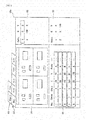
- information programmed in the control device 40 can be displayed on a screen 32a of the data input device 32.
- a board/group selection section 50, a display divided board selection section 52, a board layout display section 54, a coordinates display section 56, an offset amount within the group display unit 58, and an inter-group offset amount display section 60 are displayed on the screen 32a.
- display of the board layout display section 54 and the coordinates display section 56 can be switched between the entirety (ALL) of the printed circuit board and the selected group (or block).
- the entirety (ALL) of the printed circuit board is selected, an image of the entirety of the printed circuit board is displayed on the board layout display section 54, and coordinates of the entire electronic component mounted on the printed circuit board are displayed on the coordinates display section 56.
- the divided board within the selected group is displayed on the board layout display section 54, coordinates of the electronic component mounted on the divided board within the selected group is displayed on the coordinates display section 56, and an offset amount between the respective groups is displayed on the offset amount within the group display unit 58.
- the entirety (ALL) of the printed circuit board is selected in the display divided board selection section 52, by selecting some of the divided boards to be set one group among the multiple divided boards displayed on the board layout display section 54, and by selecting a group determination unit (not illustrated) by a user, it is possible to determine one group.
- the selected divided board is represented by a color different from that of another divided board, and a background color of coordinates representing a corresponding divided board displayed on the coordinates display section 56 is displayed by a color different from a background color of coordinates of another divided board.
- the user can input the operation program of the mounting head 22 to the control device 40 by using the data input device 32.
- the user can input the entirety of the operation program of the mounting head 22, and can input a part (for example, setting of origin of printed circuit board 34, mounting order of electronic component within one divided board, or the like) of the operation program to the control device 40.
- Fig. 5 to Fig. 8 show schematically a shape of the printed circuit board 34 and a suction nozzle 42.
- Fig. 6 and Fig. 8 a part of the divided boards among the divided boards included in the printed circuit board 34.
- the mounting head 22 includes four suction nozzles 42a to 42d.
- one group 134 is configured by four divided boards 134a to 134d among the printed circuit boards 34.
- the suction nozzles 42a to 42d are opposed at the same positions of respective divided boards 134a to 134d. Therefore, after moving the mounting head 22 to a predetermined position on the printed circuit board 34, it is possible to mount the electronic components on respective divided boards 134a to 134d without further moving the mounting head 22.
- FIG. 7 shows a mounting head 122 including two suction nozzles 142a and 142b.
- the suction nozzles 142a and 142b are disposed in an X-axis direction.
- the suction nozzles 142a and 142b are placed on a divided board 134a and a divided board 234d. Therefore, in a case where the electronic components are mounted on the printed circuit board 34 by using the mounting head 122, the divided boards 134a and 234d at positions which are separated from each other by three positions are set as one group 1034.
- divided boards 134b and 234d are set as one group 1134.
- the same electronic components are sucked to the suction nozzles 142a and 142b, and the mounting head 122 is moved to a predetermined position on the printed circuit board 34, it is possible to mount the electronic components on the divided board within one group without further moving the mounting head 122.
- the reference divided board and the divided board to be grouped are selected by the following procedures (1) to (3).
- selection of the divided board to be the same group as that of the reference divided board in the procedure by using an interval between the suction heads of the first and second positions as the interval A, and similarly, selection of the divided board to be the same group as that of the reference divided board in the procedure by using an interval between the suction heads of the second and third positions as the interval A, may be repeated.
- the group may be determined by repeating the same procedure as the procedure by using the interval of the suction head in the Y-axis direction as the interval A.
- the divided board close to the interval between the suction heads may be selected as one group.
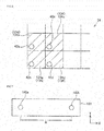
- Fig. 9 shows the group 134 and a group 234 adjacent to the group 134 among the printed circuit board 34 shown in Fig. 6 .
- the group 134 is referred to as a group 1
- the group 234 is referred to as a group 2.
- numbers 1 to 8 attached to the divided board are numbers of the divided board stored in the control device 40.
- boards are referred to as divided boards 1 to 8. Data shown in Figs. 10 , 11, and 13 is stored in the control device 40.
- the coordinates of the group 1 and the group 2 can be referred to as the origin of the group 1 and the group 2.
- the coordinates of the group 2 correspond to the offset data (first offset data) with respect to the group 1 (reference group).
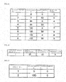
- Fig. 11 shows coordinates of the divided boards 1 to 4 stored in the control device 40, and a mounting order of the electronic components. That is, Fig. 11 shows coordinates of the divided board and the mounting order included in the group 1.
- the coordinates of the divided boards 1 to 4 can be referred to as the origins of respective divided boards 1 to 4. Coordinates of divided boards 2 to 4 correspond to the offset data (second offset data) with respect to the divided board 1 (reference divided board).
- Fig. 12 shows coordinates of the divided boards 5 to 8 and a mounting order of the electronic components.
- the coordinates of the divided boards 5 to 8 and the mounting order are not stored in the control device 40.
- the coordinates and the mounting order shown in Fig. 12 are obtained by data shown in Fig. 10 and Fig. 11 .
- a numerical value of the coordinates (first offset data) of the group 2 shown in Fig. 10 is added to a numerical value of the coordinates shown in Fig. 11 .
- the mounting order shown in Fig. 12 is a mounting order through the group 1 and the group 2.
- numerical values shown in parentheses are mounting orders of the electronic components within the group 2, and the same as the mounting order of the electronic component in the group 1 shown in Fig. 11 .
- Fig. 13 shows a type (component A) of the electronic components mounted on the divided board 1, and the center coordinates of the electronic component when the electronic components are mounted on the divided board 1. Specifically, the coordinates (origin) of the divided board 1 represent coordinates at which the center of the electronic component is positioned.
- Data shown in Figs. 10 , 11, and 13 is stored in the control device 40.
- the control device 40 does not store data of the coordinates and the mounting order with respect to the divided boards 5 to 8 within the group 2 shown in Fig. 12 . Therefore, it is possible for the control device 40 to decrease a memory capacity compared to the control device of storing data of the coordinates and the mounting order with respect to the entire divided boards on which the electronic components are mounted.
- one group 101 is configured by the divided boards 1 to 8. That is, the number of divided boards included in the group 101 is greater than the number (four) of the suction nozzles included in the mounting head 22.
- Fig. 15 shows coordinates (origin) of the divided boards 1 to 8 and a mounting order of the electronic components stored in the control device 40. That is, Fig. 15 shows the coordinates of the divided board and the mounting order included in the group 101.
- the coordinates of the divided board 2 to the divided board 8 correspond to the offset data (second offset data) with respect to the divided board 1 (reference divided board).
- Fig. 16 shows a type (component A) of the electronic components mounted on the divided board 1, and center coordinates of the electronic components when the electronic components are mounted on the divided board 1. Specifically, the coordinates of the center position of the electronic component with respect to the coordinates (origin) of the divided board 1 are shown.
- the same number of the divided boards as the number of the suction nozzles may be set as one group (first embodiment), and the divided boards of numbers greater than the number of the suction nozzles may be set as one group (second embodiment).
- FIG. 17 to 20 another form of data stored in the control device 40 and an order for mounting the electronic components on the printed circuit board 34 will be described.
- an example in which the electronic components are mounted on the printed circuit board 34 shown in Fig. 6 will be described by using the mounting head 22 shown in Fig. 5 .
- a case where multiple components are mounted on one divided board will be described.
- description of the same features as those described in the first or second embodiment may be omitted.
- Fig. 17 shows coordinates (origin of group 1 and group 2) of the group 1 and the group 2 stored in the control device 40.
- Fig. 18 shows coordinates of the divided boards 1 to 4, and a mounting order of the electronic component stored in the control device 40.
- Fig. 19 shows center coordinates of the electronic components A and B when electronic components A and B are mounted on the divided board 1 (reference divided board), types (component A and component B) of the electronic components mounted on the divided board 1, and a type of the suction nozzle to be used. As described in Fig. 19 , in the embodiment, three electronic components are mounted within the divided board.
- nozzles A and B two types of suction nozzles
- productivity is reduced (time required for mounting electronic components becomes longer). Therefore, in the embodiment, the mounting of the electronic components is performed in an order in which replacement of the suction nozzle is reduced.
- Fig. 20 shows an order for mounting the electronic components, a mounting position of the electronic components within the divided board, and a group on which the electronic components are mounted.
- the component A is mounted on a position "1" within the board of the groups 1 and 2
- the component A is mounted on a position "2" within the board of the groups 1 and 2 (see also Fig. 19 ).
- the component B is mounted on a position "3" within the board of the groups 1 and 2. That is, before mounting of the entire components (components A and B) with respect to the group 1 is finished, mounting of the component A with respect to the group 2 is performed, and the mounting of the component B with respect to the group 1 is performed again.
- a position corresponding to the position "1" within the board shown in Fig. 19 is selected from each of the divided boards 1 to 4 (see also Fig. 9 ) included in the group 1. Accordingly, the components A sucked by using four suction nozzles are continuously mounted on the position "1" within the selected board. Thereafter, the components A are continuously mounted on the position "2" within the board of the boards 1 to 4 (mounting orders 1 and 2 of Fig. 20 ).
- the components A are continuously mounted on the position "1" within the board of the divided boards 5 to 8 included in the group 2, and the components A are continuously mounted on the position "2" within the board of the divided boards 5 to 8 (mounting orders 3 and 4 of Fig. 20 ). Thereafter, the entire four suction nozzles are replaced from a nozzle A to a nozzle B. Thereafter, the components B are continuously mounted on the position "3" within the board of the boards 1 to 4 (group 1), and the components B are continuously mounted on the position "3" within the board of the boards 5 to 8 (group 2) (mounting orders 5 and 6 of Fig. 20 ).
- the mounting order of the electronic components shown in Fig. 20 is determined based on the offset data (first offset data) of the group 2 with respect to the reference group (group 1) shown in Fig. 17 , the offset data (second offset data) of the divided boards 2 to 4 with respect to the reference divided board (divided board 1) shown in Fig. 18 , the type of the electronic components mounted on the reference divided board shown in Fig. 19 , and the type of the suction nozzles to be used.
- the number of divided boards included within one group can be determined through the following procedures.
- the mounting head in which four suction nozzles are disposed so as to form a rectangle is described.
- the mounting head rotary head
- the multiple suction nozzles are disposed so as to form a circle.
- the number of divided boards included in the one group is determined based on the numerical value I (the number of divided boards included in one group) is calculated, the number of divided boards included in the printed circuit board, and the number of the electronic components mounted on the one divided board.
- the rotary head it is possible to control an operation of the mounting head based on the mounting position data of the electronic components within one divided board among the multiple divided boards within one group, the offset data with respect to the one divided board of the multiple divided boards within one group, and order data for mounting the electronic components within one group.
Landscapes
- Engineering & Computer Science (AREA)
- Manufacturing & Machinery (AREA)
- Microelectronics & Electronic Packaging (AREA)
- Operations Research (AREA)
- Automation & Control Theory (AREA)
- Supply And Installment Of Electrical Components (AREA)
Applications Claiming Priority (1)
| Application Number | Priority Date | Filing Date | Title |
|---|---|---|---|
| PCT/JP2014/079866 WO2016075760A1 (fr) | 2014-11-11 | 2014-11-11 | Dispositif de commande pour dispositif de fixation de composant électronique, et dispositif de saisie de données pour dispositif de commande |
Publications (3)
| Publication Number | Publication Date |
|---|---|
| EP3220730A1 true EP3220730A1 (fr) | 2017-09-20 |
| EP3220730A4 EP3220730A4 (fr) | 2017-12-13 |
| EP3220730B1 EP3220730B1 (fr) | 2020-12-23 |
Family
ID=55953873
Family Applications (1)
| Application Number | Title | Priority Date | Filing Date |
|---|---|---|---|
| EP14905944.6A Active EP3220730B1 (fr) | 2014-11-11 | 2014-11-11 | Dispositif de commande pour dispositif de fixation de composant électronique |
Country Status (5)
| Country | Link |
|---|---|
| US (1) | US11140801B2 (fr) |
| EP (1) | EP3220730B1 (fr) |
| JP (1) | JP6522644B2 (fr) |
| CN (1) | CN107079617B (fr) |
| WO (1) | WO2016075760A1 (fr) |
Families Citing this family (5)
| Publication number | Priority date | Publication date | Assignee | Title |
|---|---|---|---|---|
| EP3125664B1 (fr) * | 2014-03-25 | 2018-11-28 | FUJI Corporation | Dispositif de montage de composants |
| DE112015007122T5 (de) * | 2015-11-13 | 2018-07-26 | Yamaha Hatsudoki Kabushiki Kaisha | Bauteilmontagevorrichtung, Bauteilmontageverfahren und Oberflächenmontagegerät |
| WO2019163018A1 (fr) * | 2018-02-21 | 2019-08-29 | 株式会社Fuji | Système de montage de composant et procédé de saisie de composant |
| JP7089633B2 (ja) * | 2019-03-05 | 2022-06-22 | 株式会社Fuji | 補正量算出装置、部品装着機および補正量算出方法 |
| CN116095980B (zh) * | 2022-11-08 | 2023-08-22 | 哈尔滨工业大学 | 一种基于最大二分配的贴片机吸嘴分配方法 |
Family Cites Families (30)
| Publication number | Priority date | Publication date | Assignee | Title |
|---|---|---|---|---|
| JP2501205B2 (ja) | 1986-11-26 | 1996-05-29 | シチズン時計株式会社 | 電子部品自動挿入機における部品挿入位置補正方法 |
| JPH09204454A (ja) * | 1996-01-26 | 1997-08-05 | Matsushita Electric Ind Co Ltd | 部品電子カタログ |
| JP3562325B2 (ja) * | 1998-07-16 | 2004-09-08 | 松下電器産業株式会社 | 電子部品の実装方法 |
| US6571462B1 (en) * | 1999-04-27 | 2003-06-03 | Matsushita Electric Industrial Co., Ltd | Electronic component mounting apparatus using duplicate sources of components |
| JP3768040B2 (ja) | 1999-08-31 | 2006-04-19 | 株式会社日立ハイテクインスツルメンツ | 電子部品装着装置 |
| DE60024375T2 (de) * | 1999-09-03 | 2006-06-14 | Matsushita Electric Industrial Co Ltd | Bauteilen-bestückungsverfahren und Einrichtung |
| JP2007306040A (ja) | 1999-09-27 | 2007-11-22 | Matsushita Electric Ind Co Ltd | 部品実装方法及び部品実装装置 |
| EP1816906B1 (fr) | 1999-09-27 | 2008-07-16 | Matsushita Electric Industrial Co., Ltd. | Procédé de montage et appareil de montage |
| JP3531586B2 (ja) * | 2000-06-12 | 2004-05-31 | 松下電器産業株式会社 | 表示パネルの組立装置および組立方法 |
| JP3877501B2 (ja) * | 2000-07-07 | 2007-02-07 | 松下電器産業株式会社 | 部品認識データ作成方法及び作成装置並びに電子部品実装装置及び記録媒体 |
| DE60136378D1 (de) * | 2000-08-22 | 2008-12-11 | Matsushita Electric Industrial Co Ltd | Einrichtung und verfahren zur montage von teilen |
| US6862803B2 (en) * | 2000-08-29 | 2005-03-08 | Matsushita Electric Industrial Co., Ltd. | Method for mounting electronic component |
| JP4514321B2 (ja) | 2000-12-08 | 2010-07-28 | パナソニック株式会社 | 部品実装装置 |
| JP3674516B2 (ja) | 2001-02-23 | 2005-07-20 | 松下電器産業株式会社 | 部品実装順序決定方法、部品実装方法、部品実装機、部品実装順序決定装置、及び、部品実装順序決定プログラム |
| JP2002368495A (ja) * | 2001-06-08 | 2002-12-20 | Matsushita Electric Ind Co Ltd | 部品実装装置及び部品実装方法 |
| JP3589658B2 (ja) * | 2001-09-28 | 2004-11-17 | 松下電器産業株式会社 | 最適化装置、装着装置及び電子部品装着システム |
| JP3943361B2 (ja) | 2001-10-09 | 2007-07-11 | 松下電器産業株式会社 | 部品実装方法及び部品実装装置、並びに実装データ作成プログラム及び記録媒体 |
| JP3997101B2 (ja) * | 2002-03-18 | 2007-10-24 | 富士機械製造株式会社 | 電子回路部品装着システム |
| JP4255267B2 (ja) * | 2002-11-22 | 2009-04-15 | 富士機械製造株式会社 | 作業プログラム適否判定装置を含む対基板作業システムおよび作業プログラム適否判定プログラム |
| TW200419640A (en) * | 2003-02-25 | 2004-10-01 | Matsushita Electric Industrial Co Ltd | Electronic component placement machine and electronic component placement method |
| CN1846223B (zh) * | 2003-09-01 | 2012-09-05 | 松下电器产业株式会社 | 元件装配顺序的优化方法和元件装配顺序的优化设备 |
| US7353589B2 (en) * | 2003-10-15 | 2008-04-08 | Matsushita Electric Industrial Co., Ltd. | Component mounting apparatus |
| JP4417779B2 (ja) * | 2004-05-31 | 2010-02-17 | 株式会社日立ハイテクインスツルメンツ | 電子部品装着装置及び電子部品装着方法 |
| JP4563205B2 (ja) * | 2005-02-08 | 2010-10-13 | 富士機械製造株式会社 | 実装された電子部品の検査方法及び装置 |
| JP4887234B2 (ja) * | 2007-07-31 | 2012-02-29 | 株式会社日立ハイテクインスツルメンツ | 電子部品装着装置 |
| KR101649855B1 (ko) * | 2010-11-12 | 2016-08-23 | 한화테크윈 주식회사 | 가변 피치 헤드를 이용한 부품 실장 최적화 방법 및 그 방법을 이용한 부품 실장기 |
| JP5645681B2 (ja) * | 2011-01-24 | 2014-12-24 | 株式会社日立ハイテクインスツルメンツ | 部品実装装置の設定を算出する演算装置、部品実装装置、及びプログラム |
| DE102013207599A1 (de) * | 2013-04-25 | 2014-10-30 | Finetech Gmbh & Co.Kg | Platziervorrichtung und Platzierverfahren zum lagegenauen Ausrichten und /oder Bestücken eines Substrates mit einem Bauelement |
| JP6031679B2 (ja) * | 2013-07-30 | 2016-11-24 | パナソニックIpマネジメント株式会社 | 部品実装システムにおける段取り替え作業の指示方法および部品実装システム |
| DE102015220746A1 (de) * | 2015-10-23 | 2017-04-27 | Ersa Gmbh | Verfahren und Vorrichtung zur Platzierung elektronischer Bauteile |
-
2014
- 2014-11-11 JP JP2016558479A patent/JP6522644B2/ja active Active
- 2014-11-11 WO PCT/JP2014/079866 patent/WO2016075760A1/fr not_active Ceased
- 2014-11-11 EP EP14905944.6A patent/EP3220730B1/fr active Active
- 2014-11-11 US US15/525,813 patent/US11140801B2/en active Active
- 2014-11-11 CN CN201480083216.7A patent/CN107079617B/zh active Active
Also Published As
| Publication number | Publication date |
|---|---|
| JP6522644B2 (ja) | 2019-05-29 |
| CN107079617B (zh) | 2019-08-06 |
| CN107079617A (zh) | 2017-08-18 |
| US20170325371A1 (en) | 2017-11-09 |
| EP3220730A4 (fr) | 2017-12-13 |
| US11140801B2 (en) | 2021-10-05 |
| WO2016075760A1 (fr) | 2016-05-19 |
| EP3220730B1 (fr) | 2020-12-23 |
| JPWO2016075760A1 (ja) | 2017-08-24 |
Similar Documents
| Publication | Publication Date | Title |
|---|---|---|
| EP3220730B1 (fr) | Dispositif de commande pour dispositif de fixation de composant électronique | |
| CN103636300B (zh) | 电子电路元件安装系统 | |
| JP4943299B2 (ja) | 部品実装装置のフィーダ配置方法 | |
| JP6491317B2 (ja) | 部品実装ラインの最適化装置および部品実装ラインの最適化方法 | |
| CN102740673A (zh) | 元件安装装置、信息处理装置和方法以及基板制造方法 | |
| US20160196520A1 (en) | Managing method and managing device of electronic component mounting system having plural production lines | |
| EP3082389B1 (fr) | Dispositif de création de données d'instructions de capture de composant de circuit électronique et dispositif de montage de composant de circuit électronique | |
| JP2012134303A (ja) | 電子部品装着装置、および、電子部品装着方法 | |
| CN110603909A (zh) | 换产调整作业的设定装置及换产调整作业的设定方法 | |
| JP5701430B2 (ja) | 電子回路部品装着装置 | |
| JP5701067B2 (ja) | 部品補給時の案内装置 | |
| JP2010135775A (ja) | 電子部品の装着方法、電子部品装着装置、電子部品装着装置の電子部品装着順序決定方法及び電子部品装着装置の装着データ作成方法 | |
| CN102111988A (zh) | 电子元件的安装方法 | |
| EP3484255B1 (fr) | Système de création de plan de production et procédé de création de plan de production | |
| EP3606313A1 (fr) | Engin de chantier associé à un substrat | |
| EP3806611B1 (fr) | Dispositif de détermination, dispositif de montage de composant doté de celui-ci, et procédé de détermination | |
| EP3021652B1 (fr) | Procédé permettant d'allouer des composants électroniques et système de montage de composants électroniques | |
| JP7721479B2 (ja) | 生産計画作成装置及び部品実装システム | |
| JP2006171916A (ja) | 生産計画方法 | |
| CN107114007B (zh) | 电子元件供给系统 | |
| JP4891290B2 (ja) | 実装条件決定方法 | |
| JP2021072366A (ja) | 部品実装装置 | |
| JP2021072367A (ja) | 部品実装装置 |
Legal Events
| Date | Code | Title | Description |
|---|---|---|---|
| STAA | Information on the status of an ep patent application or granted ep patent |
Free format text: STATUS: THE INTERNATIONAL PUBLICATION HAS BEEN MADE |
|
| PUAI | Public reference made under article 153(3) epc to a published international application that has entered the european phase |
Free format text: ORIGINAL CODE: 0009012 |
|
| STAA | Information on the status of an ep patent application or granted ep patent |
Free format text: STATUS: REQUEST FOR EXAMINATION WAS MADE |
|
| 17P | Request for examination filed |
Effective date: 20170511 |
|
| AK | Designated contracting states |
Kind code of ref document: A1 Designated state(s): AL AT BE BG CH CY CZ DE DK EE ES FI FR GB GR HR HU IE IS IT LI LT LU LV MC MK MT NL NO PL PT RO RS SE SI SK SM TR |
|
| AX | Request for extension of the european patent |
Extension state: BA ME |
|
| A4 | Supplementary search report drawn up and despatched |
Effective date: 20171113 |
|
| RIC1 | Information provided on ipc code assigned before grant |
Ipc: H05K 13/08 20060101ALI20171107BHEP Ipc: H05K 13/04 20060101AFI20171107BHEP |
|
| DAX | Request for extension of the european patent (deleted) | ||
| RAP1 | Party data changed (applicant data changed or rights of an application transferred) |
Owner name: FUJI CORPORATION |
|
| RIN1 | Information on inventor provided before grant (corrected) |
Inventor name: KUBOTA TOMOKATSU Inventor name: IISAKA JUN Inventor name: OYAMA SHIGETO |
|
| STAA | Information on the status of an ep patent application or granted ep patent |
Free format text: STATUS: EXAMINATION IS IN PROGRESS |
|
| 17Q | First examination report despatched |
Effective date: 20191121 |
|
| GRAP | Despatch of communication of intention to grant a patent |
Free format text: ORIGINAL CODE: EPIDOSNIGR1 |
|
| STAA | Information on the status of an ep patent application or granted ep patent |
Free format text: STATUS: GRANT OF PATENT IS INTENDED |
|
| INTG | Intention to grant announced |
Effective date: 20200922 |
|
| GRAS | Grant fee paid |
Free format text: ORIGINAL CODE: EPIDOSNIGR3 |
|
| GRAA | (expected) grant |
Free format text: ORIGINAL CODE: 0009210 |
|
| STAA | Information on the status of an ep patent application or granted ep patent |
Free format text: STATUS: THE PATENT HAS BEEN GRANTED |
|
| AK | Designated contracting states |
Kind code of ref document: B1 Designated state(s): AL AT BE BG CH CY CZ DE DK EE ES FI FR GB GR HR HU IE IS IT LI LT LU LV MC MK MT NL NO PL PT RO RS SE SI SK SM TR |
|
| REG | Reference to a national code |
Ref country code: GB Ref legal event code: FG4D |
|
| REG | Reference to a national code |
Ref country code: DE Ref legal event code: R096 Ref document number: 602014073702 Country of ref document: DE |
|
| REG | Reference to a national code |
Ref country code: AT Ref legal event code: REF Ref document number: 1348982 Country of ref document: AT Kind code of ref document: T Effective date: 20210115 |
|
| REG | Reference to a national code |
Ref country code: IE Ref legal event code: FG4D |
|
| PG25 | Lapsed in a contracting state [announced via postgrant information from national office to epo] |
Ref country code: NO Free format text: LAPSE BECAUSE OF FAILURE TO SUBMIT A TRANSLATION OF THE DESCRIPTION OR TO PAY THE FEE WITHIN THE PRESCRIBED TIME-LIMIT Effective date: 20210323 Ref country code: FI Free format text: LAPSE BECAUSE OF FAILURE TO SUBMIT A TRANSLATION OF THE DESCRIPTION OR TO PAY THE FEE WITHIN THE PRESCRIBED TIME-LIMIT Effective date: 20201223 Ref country code: RS Free format text: LAPSE BECAUSE OF FAILURE TO SUBMIT A TRANSLATION OF THE DESCRIPTION OR TO PAY THE FEE WITHIN THE PRESCRIBED TIME-LIMIT Effective date: 20201223 Ref country code: GR Free format text: LAPSE BECAUSE OF FAILURE TO SUBMIT A TRANSLATION OF THE DESCRIPTION OR TO PAY THE FEE WITHIN THE PRESCRIBED TIME-LIMIT Effective date: 20210324 |
|
| REG | Reference to a national code |
Ref country code: AT Ref legal event code: MK05 Ref document number: 1348982 Country of ref document: AT Kind code of ref document: T Effective date: 20201223 |
|
| REG | Reference to a national code |
Ref country code: NL Ref legal event code: MP Effective date: 20201223 |
|
| PG25 | Lapsed in a contracting state [announced via postgrant information from national office to epo] |
Ref country code: LV Free format text: LAPSE BECAUSE OF FAILURE TO SUBMIT A TRANSLATION OF THE DESCRIPTION OR TO PAY THE FEE WITHIN THE PRESCRIBED TIME-LIMIT Effective date: 20201223 Ref country code: SE Free format text: LAPSE BECAUSE OF FAILURE TO SUBMIT A TRANSLATION OF THE DESCRIPTION OR TO PAY THE FEE WITHIN THE PRESCRIBED TIME-LIMIT Effective date: 20201223 Ref country code: BG Free format text: LAPSE BECAUSE OF FAILURE TO SUBMIT A TRANSLATION OF THE DESCRIPTION OR TO PAY THE FEE WITHIN THE PRESCRIBED TIME-LIMIT Effective date: 20210323 |
|
| PG25 | Lapsed in a contracting state [announced via postgrant information from national office to epo] |
Ref country code: NL Free format text: LAPSE BECAUSE OF FAILURE TO SUBMIT A TRANSLATION OF THE DESCRIPTION OR TO PAY THE FEE WITHIN THE PRESCRIBED TIME-LIMIT Effective date: 20201223 Ref country code: HR Free format text: LAPSE BECAUSE OF FAILURE TO SUBMIT A TRANSLATION OF THE DESCRIPTION OR TO PAY THE FEE WITHIN THE PRESCRIBED TIME-LIMIT Effective date: 20201223 |
|
| REG | Reference to a national code |
Ref country code: LT Ref legal event code: MG9D |
|
| PG25 | Lapsed in a contracting state [announced via postgrant information from national office to epo] |
Ref country code: LT Free format text: LAPSE BECAUSE OF FAILURE TO SUBMIT A TRANSLATION OF THE DESCRIPTION OR TO PAY THE FEE WITHIN THE PRESCRIBED TIME-LIMIT Effective date: 20201223 Ref country code: RO Free format text: LAPSE BECAUSE OF FAILURE TO SUBMIT A TRANSLATION OF THE DESCRIPTION OR TO PAY THE FEE WITHIN THE PRESCRIBED TIME-LIMIT Effective date: 20201223 Ref country code: SK Free format text: LAPSE BECAUSE OF FAILURE TO SUBMIT A TRANSLATION OF THE DESCRIPTION OR TO PAY THE FEE WITHIN THE PRESCRIBED TIME-LIMIT Effective date: 20201223 Ref country code: PT Free format text: LAPSE BECAUSE OF FAILURE TO SUBMIT A TRANSLATION OF THE DESCRIPTION OR TO PAY THE FEE WITHIN THE PRESCRIBED TIME-LIMIT Effective date: 20210423 Ref country code: SM Free format text: LAPSE BECAUSE OF FAILURE TO SUBMIT A TRANSLATION OF THE DESCRIPTION OR TO PAY THE FEE WITHIN THE PRESCRIBED TIME-LIMIT Effective date: 20201223 Ref country code: EE Free format text: LAPSE BECAUSE OF FAILURE TO SUBMIT A TRANSLATION OF THE DESCRIPTION OR TO PAY THE FEE WITHIN THE PRESCRIBED TIME-LIMIT Effective date: 20201223 Ref country code: CZ Free format text: LAPSE BECAUSE OF FAILURE TO SUBMIT A TRANSLATION OF THE DESCRIPTION OR TO PAY THE FEE WITHIN THE PRESCRIBED TIME-LIMIT Effective date: 20201223 |
|
| PG25 | Lapsed in a contracting state [announced via postgrant information from national office to epo] |
Ref country code: AT Free format text: LAPSE BECAUSE OF FAILURE TO SUBMIT A TRANSLATION OF THE DESCRIPTION OR TO PAY THE FEE WITHIN THE PRESCRIBED TIME-LIMIT Effective date: 20201223 Ref country code: PL Free format text: LAPSE BECAUSE OF FAILURE TO SUBMIT A TRANSLATION OF THE DESCRIPTION OR TO PAY THE FEE WITHIN THE PRESCRIBED TIME-LIMIT Effective date: 20201223 |
|
| REG | Reference to a national code |
Ref country code: DE Ref legal event code: R097 Ref document number: 602014073702 Country of ref document: DE |
|
| PG25 | Lapsed in a contracting state [announced via postgrant information from national office to epo] |
Ref country code: IS Free format text: LAPSE BECAUSE OF FAILURE TO SUBMIT A TRANSLATION OF THE DESCRIPTION OR TO PAY THE FEE WITHIN THE PRESCRIBED TIME-LIMIT Effective date: 20210423 |
|
| PG25 | Lapsed in a contracting state [announced via postgrant information from national office to epo] |
Ref country code: AL Free format text: LAPSE BECAUSE OF FAILURE TO SUBMIT A TRANSLATION OF THE DESCRIPTION OR TO PAY THE FEE WITHIN THE PRESCRIBED TIME-LIMIT Effective date: 20201223 Ref country code: IT Free format text: LAPSE BECAUSE OF FAILURE TO SUBMIT A TRANSLATION OF THE DESCRIPTION OR TO PAY THE FEE WITHIN THE PRESCRIBED TIME-LIMIT Effective date: 20201223 |
|
| PLBE | No opposition filed within time limit |
Free format text: ORIGINAL CODE: 0009261 |
|
| STAA | Information on the status of an ep patent application or granted ep patent |
Free format text: STATUS: NO OPPOSITION FILED WITHIN TIME LIMIT |
|
| PG25 | Lapsed in a contracting state [announced via postgrant information from national office to epo] |
Ref country code: DK Free format text: LAPSE BECAUSE OF FAILURE TO SUBMIT A TRANSLATION OF THE DESCRIPTION OR TO PAY THE FEE WITHIN THE PRESCRIBED TIME-LIMIT Effective date: 20201223 |
|
| 26N | No opposition filed |
Effective date: 20210924 |
|
| PG25 | Lapsed in a contracting state [announced via postgrant information from national office to epo] |
Ref country code: ES Free format text: LAPSE BECAUSE OF FAILURE TO SUBMIT A TRANSLATION OF THE DESCRIPTION OR TO PAY THE FEE WITHIN THE PRESCRIBED TIME-LIMIT Effective date: 20201223 |
|
| PG25 | Lapsed in a contracting state [announced via postgrant information from national office to epo] |
Ref country code: SI Free format text: LAPSE BECAUSE OF FAILURE TO SUBMIT A TRANSLATION OF THE DESCRIPTION OR TO PAY THE FEE WITHIN THE PRESCRIBED TIME-LIMIT Effective date: 20201223 |
|
| PG25 | Lapsed in a contracting state [announced via postgrant information from national office to epo] |
Ref country code: IS Free format text: LAPSE BECAUSE OF FAILURE TO SUBMIT A TRANSLATION OF THE DESCRIPTION OR TO PAY THE FEE WITHIN THE PRESCRIBED TIME-LIMIT Effective date: 20210423 |
|
| PG25 | Lapsed in a contracting state [announced via postgrant information from national office to epo] |
Ref country code: MC Free format text: LAPSE BECAUSE OF FAILURE TO SUBMIT A TRANSLATION OF THE DESCRIPTION OR TO PAY THE FEE WITHIN THE PRESCRIBED TIME-LIMIT Effective date: 20201223 |
|
| REG | Reference to a national code |
Ref country code: CH Ref legal event code: PL |
|
| GBPC | Gb: european patent ceased through non-payment of renewal fee |
Effective date: 20211111 |
|
| PG25 | Lapsed in a contracting state [announced via postgrant information from national office to epo] |
Ref country code: LU Free format text: LAPSE BECAUSE OF NON-PAYMENT OF DUE FEES Effective date: 20211111 Ref country code: BE Free format text: LAPSE BECAUSE OF NON-PAYMENT OF DUE FEES Effective date: 20211130 |
|
| REG | Reference to a national code |
Ref country code: BE Ref legal event code: MM Effective date: 20211130 |
|
| PG25 | Lapsed in a contracting state [announced via postgrant information from national office to epo] |
Ref country code: LI Free format text: LAPSE BECAUSE OF NON-PAYMENT OF DUE FEES Effective date: 20211130 Ref country code: CH Free format text: LAPSE BECAUSE OF NON-PAYMENT OF DUE FEES Effective date: 20211130 |
|
| PG25 | Lapsed in a contracting state [announced via postgrant information from national office to epo] |
Ref country code: IE Free format text: LAPSE BECAUSE OF NON-PAYMENT OF DUE FEES Effective date: 20211111 Ref country code: GB Free format text: LAPSE BECAUSE OF NON-PAYMENT OF DUE FEES Effective date: 20211111 |
|
| PG25 | Lapsed in a contracting state [announced via postgrant information from national office to epo] |
Ref country code: FR Free format text: LAPSE BECAUSE OF NON-PAYMENT OF DUE FEES Effective date: 20211130 |
|
| PG25 | Lapsed in a contracting state [announced via postgrant information from national office to epo] |
Ref country code: HU Free format text: LAPSE BECAUSE OF FAILURE TO SUBMIT A TRANSLATION OF THE DESCRIPTION OR TO PAY THE FEE WITHIN THE PRESCRIBED TIME-LIMIT; INVALID AB INITIO Effective date: 20141111 |
|
| P01 | Opt-out of the competence of the unified patent court (upc) registered |
Effective date: 20230328 |
|
| PG25 | Lapsed in a contracting state [announced via postgrant information from national office to epo] |
Ref country code: CY Free format text: LAPSE BECAUSE OF FAILURE TO SUBMIT A TRANSLATION OF THE DESCRIPTION OR TO PAY THE FEE WITHIN THE PRESCRIBED TIME-LIMIT Effective date: 20201223 |
|
| PG25 | Lapsed in a contracting state [announced via postgrant information from national office to epo] |
Ref country code: MK Free format text: LAPSE BECAUSE OF FAILURE TO SUBMIT A TRANSLATION OF THE DESCRIPTION OR TO PAY THE FEE WITHIN THE PRESCRIBED TIME-LIMIT Effective date: 20201223 |
|
| PG25 | Lapsed in a contracting state [announced via postgrant information from national office to epo] |
Ref country code: MT Free format text: LAPSE BECAUSE OF FAILURE TO SUBMIT A TRANSLATION OF THE DESCRIPTION OR TO PAY THE FEE WITHIN THE PRESCRIBED TIME-LIMIT Effective date: 20201223 |
|
| PG25 | Lapsed in a contracting state [announced via postgrant information from national office to epo] |
Ref country code: TR Free format text: LAPSE BECAUSE OF FAILURE TO SUBMIT A TRANSLATION OF THE DESCRIPTION OR TO PAY THE FEE WITHIN THE PRESCRIBED TIME-LIMIT Effective date: 20201223 |
|
| PGFP | Annual fee paid to national office [announced via postgrant information from national office to epo] |
Ref country code: DE Payment date: 20250930 Year of fee payment: 12 |