EP3220732B1 - Schlupfsteuerung eines fahrzeugrades - Google Patents
Schlupfsteuerung eines fahrzeugrades Download PDFInfo
- Publication number
- EP3220732B1 EP3220732B1 EP15745473.7A EP15745473A EP3220732B1 EP 3220732 B1 EP3220732 B1 EP 3220732B1 EP 15745473 A EP15745473 A EP 15745473A EP 3220732 B1 EP3220732 B1 EP 3220732B1
- Authority
- EP
- European Patent Office
- Prior art keywords
- tyre
- control system
- vehicle
- air pressure
- driving torque
- Prior art date
- Legal status (The legal status is an assumption and is not a legal conclusion. Google has not performed a legal analysis and makes no representation as to the accuracy of the status listed.)
- Active
Links
Images

Classifications
-
- B—PERFORMING OPERATIONS; TRANSPORTING
- B60—VEHICLES IN GENERAL
- B60W—CONJOINT CONTROL OF VEHICLE SUB-UNITS OF DIFFERENT TYPE OR DIFFERENT FUNCTION; CONTROL SYSTEMS SPECIALLY ADAPTED FOR HYBRID VEHICLES; ROAD VEHICLE DRIVE CONTROL SYSTEMS FOR PURPOSES NOT RELATED TO THE CONTROL OF A PARTICULAR SUB-UNIT
- B60W30/00—Purposes of road vehicle drive control systems not related to the control of a particular sub-unit, e.g. of systems using conjoint control of vehicle sub-units
- B60W30/18—Propelling the vehicle
- B60W30/18172—Preventing, or responsive to skidding of wheels
-
- B—PERFORMING OPERATIONS; TRANSPORTING
- B60—VEHICLES IN GENERAL
- B60C—VEHICLE TYRES; TYRE INFLATION; TYRE CHANGING; CONNECTING VALVES TO INFLATABLE ELASTIC BODIES IN GENERAL; DEVICES OR ARRANGEMENTS RELATED TO TYRES
- B60C23/00—Devices for measuring, signalling, controlling, or distributing tyre pressure or temperature, specially adapted for mounting on vehicles; Arrangement of tyre inflating devices on vehicles, e.g. of pumps or of tanks; Tyre cooling arrangements
- B60C23/001—Devices for manually or automatically controlling or distributing tyre pressure whilst the vehicle is moving
- B60C23/003—Devices for manually or automatically controlling or distributing tyre pressure whilst the vehicle is moving comprising rotational joints between vehicle-mounted pressure sources and the tyres
- B60C23/00309—Devices for manually or automatically controlling or distributing tyre pressure whilst the vehicle is moving comprising rotational joints between vehicle-mounted pressure sources and the tyres characterised by the location of the components, e.g. valves, sealings, conduits or sensors
- B60C23/00318—Devices for manually or automatically controlling or distributing tyre pressure whilst the vehicle is moving comprising rotational joints between vehicle-mounted pressure sources and the tyres characterised by the location of the components, e.g. valves, sealings, conduits or sensors on the wheels or the hubs
-
- A—HUMAN NECESSITIES
- A01—AGRICULTURE; FORESTRY; ANIMAL HUSBANDRY; HUNTING; TRAPPING; FISHING
- A01B—SOIL WORKING IN AGRICULTURE OR FORESTRY; PARTS, DETAILS, OR ACCESSORIES OF AGRICULTURAL MACHINES OR IMPLEMENTS, IN GENERAL
- A01B63/00—Lifting or adjusting devices or arrangements for agricultural machines or implements
- A01B63/02—Lifting or adjusting devices or arrangements for agricultural machines or implements for implements mounted on tractors
- A01B63/10—Lifting or adjusting devices or arrangements for agricultural machines or implements for implements mounted on tractors operated by hydraulic or pneumatic means
- A01B63/111—Lifting or adjusting devices or arrangements for agricultural machines or implements for implements mounted on tractors operated by hydraulic or pneumatic means regulating working depth of implements
- A01B63/112—Lifting or adjusting devices or arrangements for agricultural machines or implements for implements mounted on tractors operated by hydraulic or pneumatic means regulating working depth of implements to control draught load, i.e. tractive force
-
- B—PERFORMING OPERATIONS; TRANSPORTING
- B60—VEHICLES IN GENERAL
- B60C—VEHICLE TYRES; TYRE INFLATION; TYRE CHANGING; CONNECTING VALVES TO INFLATABLE ELASTIC BODIES IN GENERAL; DEVICES OR ARRANGEMENTS RELATED TO TYRES
- B60C23/00—Devices for measuring, signalling, controlling, or distributing tyre pressure or temperature, specially adapted for mounting on vehicles; Arrangement of tyre inflating devices on vehicles, e.g. of pumps or of tanks; Tyre cooling arrangements
- B60C23/001—Devices for manually or automatically controlling or distributing tyre pressure whilst the vehicle is moving
- B60C23/002—Devices for manually or automatically controlling or distributing tyre pressure whilst the vehicle is moving by monitoring conditions other than tyre pressure or deformation
-
- B—PERFORMING OPERATIONS; TRANSPORTING
- B60—VEHICLES IN GENERAL
- B60C—VEHICLE TYRES; TYRE INFLATION; TYRE CHANGING; CONNECTING VALVES TO INFLATABLE ELASTIC BODIES IN GENERAL; DEVICES OR ARRANGEMENTS RELATED TO TYRES
- B60C23/00—Devices for measuring, signalling, controlling, or distributing tyre pressure or temperature, specially adapted for mounting on vehicles; Arrangement of tyre inflating devices on vehicles, e.g. of pumps or of tanks; Tyre cooling arrangements
- B60C23/001—Devices for manually or automatically controlling or distributing tyre pressure whilst the vehicle is moving
- B60C23/003—Devices for manually or automatically controlling or distributing tyre pressure whilst the vehicle is moving comprising rotational joints between vehicle-mounted pressure sources and the tyres
- B60C23/00354—Details of valves
-
- B—PERFORMING OPERATIONS; TRANSPORTING
- B60—VEHICLES IN GENERAL
- B60C—VEHICLE TYRES; TYRE INFLATION; TYRE CHANGING; CONNECTING VALVES TO INFLATABLE ELASTIC BODIES IN GENERAL; DEVICES OR ARRANGEMENTS RELATED TO TYRES
- B60C23/00—Devices for measuring, signalling, controlling, or distributing tyre pressure or temperature, specially adapted for mounting on vehicles; Arrangement of tyre inflating devices on vehicles, e.g. of pumps or of tanks; Tyre cooling arrangements
- B60C23/001—Devices for manually or automatically controlling or distributing tyre pressure whilst the vehicle is moving
- B60C23/003—Devices for manually or automatically controlling or distributing tyre pressure whilst the vehicle is moving comprising rotational joints between vehicle-mounted pressure sources and the tyres
- B60C23/0039—Devices for manually or automatically controlling or distributing tyre pressure whilst the vehicle is moving comprising rotational joints between vehicle-mounted pressure sources and the tyres specially adapted for driven wheels
-
- B—PERFORMING OPERATIONS; TRANSPORTING
- B60—VEHICLES IN GENERAL
- B60K—ARRANGEMENT OR MOUNTING OF PROPULSION UNITS OR OF TRANSMISSIONS IN VEHICLES; ARRANGEMENT OR MOUNTING OF PLURAL DIVERSE PRIME-MOVERS IN VEHICLES; AUXILIARY DRIVES FOR VEHICLES; INSTRUMENTATION OR DASHBOARDS FOR VEHICLES; ARRANGEMENTS IN CONNECTION WITH COOLING, AIR INTAKE, GAS EXHAUST OR FUEL SUPPLY OF PROPULSION UNITS IN VEHICLES
- B60K7/00—Disposition of motor in, or adjacent to, traction wheel
- B60K7/0015—Disposition of motor in, or adjacent to, traction wheel the motor being hydraulic
-
- B—PERFORMING OPERATIONS; TRANSPORTING
- B60—VEHICLES IN GENERAL
- B60W—CONJOINT CONTROL OF VEHICLE SUB-UNITS OF DIFFERENT TYPE OR DIFFERENT FUNCTION; CONTROL SYSTEMS SPECIALLY ADAPTED FOR HYBRID VEHICLES; ROAD VEHICLE DRIVE CONTROL SYSTEMS FOR PURPOSES NOT RELATED TO THE CONTROL OF A PARTICULAR SUB-UNIT
- B60W10/00—Conjoint control of vehicle sub-units of different type or different function
- B60W10/04—Conjoint control of vehicle sub-units of different type or different function including control of propulsion units
-
- B—PERFORMING OPERATIONS; TRANSPORTING
- B60—VEHICLES IN GENERAL
- B60W—CONJOINT CONTROL OF VEHICLE SUB-UNITS OF DIFFERENT TYPE OR DIFFERENT FUNCTION; CONTROL SYSTEMS SPECIALLY ADAPTED FOR HYBRID VEHICLES; ROAD VEHICLE DRIVE CONTROL SYSTEMS FOR PURPOSES NOT RELATED TO THE CONTROL OF A PARTICULAR SUB-UNIT
- B60W10/00—Conjoint control of vehicle sub-units of different type or different function
- B60W10/04—Conjoint control of vehicle sub-units of different type or different function including control of propulsion units
- B60W10/08—Conjoint control of vehicle sub-units of different type or different function including control of propulsion units including control of electric propulsion units, e.g. motors or generators
-
- B—PERFORMING OPERATIONS; TRANSPORTING
- B60—VEHICLES IN GENERAL
- B60W—CONJOINT CONTROL OF VEHICLE SUB-UNITS OF DIFFERENT TYPE OR DIFFERENT FUNCTION; CONTROL SYSTEMS SPECIALLY ADAPTED FOR HYBRID VEHICLES; ROAD VEHICLE DRIVE CONTROL SYSTEMS FOR PURPOSES NOT RELATED TO THE CONTROL OF A PARTICULAR SUB-UNIT
- B60W10/00—Conjoint control of vehicle sub-units of different type or different function
- B60W10/10—Conjoint control of vehicle sub-units of different type or different function including control of change-speed gearings
- B60W10/101—Infinitely variable gearings
- B60W10/103—Infinitely variable gearings of fluid type
-
- B—PERFORMING OPERATIONS; TRANSPORTING
- B60—VEHICLES IN GENERAL
- B60W—CONJOINT CONTROL OF VEHICLE SUB-UNITS OF DIFFERENT TYPE OR DIFFERENT FUNCTION; CONTROL SYSTEMS SPECIALLY ADAPTED FOR HYBRID VEHICLES; ROAD VEHICLE DRIVE CONTROL SYSTEMS FOR PURPOSES NOT RELATED TO THE CONTROL OF A PARTICULAR SUB-UNIT
- B60W2300/00—Indexing codes relating to the type of vehicle
- B60W2300/15—Agricultural vehicles
-
- B—PERFORMING OPERATIONS; TRANSPORTING
- B60—VEHICLES IN GENERAL
- B60W—CONJOINT CONTROL OF VEHICLE SUB-UNITS OF DIFFERENT TYPE OR DIFFERENT FUNCTION; CONTROL SYSTEMS SPECIALLY ADAPTED FOR HYBRID VEHICLES; ROAD VEHICLE DRIVE CONTROL SYSTEMS FOR PURPOSES NOT RELATED TO THE CONTROL OF A PARTICULAR SUB-UNIT
- B60W2300/00—Indexing codes relating to the type of vehicle
- B60W2300/44—Tracked vehicles
-
- B—PERFORMING OPERATIONS; TRANSPORTING
- B60—VEHICLES IN GENERAL
- B60W—CONJOINT CONTROL OF VEHICLE SUB-UNITS OF DIFFERENT TYPE OR DIFFERENT FUNCTION; CONTROL SYSTEMS SPECIALLY ADAPTED FOR HYBRID VEHICLES; ROAD VEHICLE DRIVE CONTROL SYSTEMS FOR PURPOSES NOT RELATED TO THE CONTROL OF A PARTICULAR SUB-UNIT
- B60W2400/00—Indexing codes relating to detected, measured or calculated conditions or factors
-
- B—PERFORMING OPERATIONS; TRANSPORTING
- B60—VEHICLES IN GENERAL
- B60W—CONJOINT CONTROL OF VEHICLE SUB-UNITS OF DIFFERENT TYPE OR DIFFERENT FUNCTION; CONTROL SYSTEMS SPECIALLY ADAPTED FOR HYBRID VEHICLES; ROAD VEHICLE DRIVE CONTROL SYSTEMS FOR PURPOSES NOT RELATED TO THE CONTROL OF A PARTICULAR SUB-UNIT
- B60W2510/00—Input parameters relating to a particular sub-units
- B60W2510/08—Electric propulsion units
- B60W2510/083—Torque
-
- B—PERFORMING OPERATIONS; TRANSPORTING
- B60—VEHICLES IN GENERAL
- B60W—CONJOINT CONTROL OF VEHICLE SUB-UNITS OF DIFFERENT TYPE OR DIFFERENT FUNCTION; CONTROL SYSTEMS SPECIALLY ADAPTED FOR HYBRID VEHICLES; ROAD VEHICLE DRIVE CONTROL SYSTEMS FOR PURPOSES NOT RELATED TO THE CONTROL OF A PARTICULAR SUB-UNIT
- B60W2510/00—Input parameters relating to a particular sub-units
- B60W2510/09—Other types of propulsion units, e.g. fluid motors, or type not specified
-
- B—PERFORMING OPERATIONS; TRANSPORTING
- B60—VEHICLES IN GENERAL
- B60W—CONJOINT CONTROL OF VEHICLE SUB-UNITS OF DIFFERENT TYPE OR DIFFERENT FUNCTION; CONTROL SYSTEMS SPECIALLY ADAPTED FOR HYBRID VEHICLES; ROAD VEHICLE DRIVE CONTROL SYSTEMS FOR PURPOSES NOT RELATED TO THE CONTROL OF A PARTICULAR SUB-UNIT
- B60W2510/00—Input parameters relating to a particular sub-units
- B60W2510/10—Change speed gearings
- B60W2510/105—Output torque
-
- B—PERFORMING OPERATIONS; TRANSPORTING
- B60—VEHICLES IN GENERAL
- B60W—CONJOINT CONTROL OF VEHICLE SUB-UNITS OF DIFFERENT TYPE OR DIFFERENT FUNCTION; CONTROL SYSTEMS SPECIALLY ADAPTED FOR HYBRID VEHICLES; ROAD VEHICLE DRIVE CONTROL SYSTEMS FOR PURPOSES NOT RELATED TO THE CONTROL OF A PARTICULAR SUB-UNIT
- B60W2520/00—Input parameters relating to overall vehicle dynamics
- B60W2520/26—Wheel slip
-
- B—PERFORMING OPERATIONS; TRANSPORTING
- B60—VEHICLES IN GENERAL
- B60W—CONJOINT CONTROL OF VEHICLE SUB-UNITS OF DIFFERENT TYPE OR DIFFERENT FUNCTION; CONTROL SYSTEMS SPECIALLY ADAPTED FOR HYBRID VEHICLES; ROAD VEHICLE DRIVE CONTROL SYSTEMS FOR PURPOSES NOT RELATED TO THE CONTROL OF A PARTICULAR SUB-UNIT
- B60W2530/00—Input parameters relating to vehicle conditions or values, not covered by groups B60W2510/00 or B60W2520/00
- B60W2530/20—Tyre data
-
- B—PERFORMING OPERATIONS; TRANSPORTING
- B60—VEHICLES IN GENERAL
- B60W—CONJOINT CONTROL OF VEHICLE SUB-UNITS OF DIFFERENT TYPE OR DIFFERENT FUNCTION; CONTROL SYSTEMS SPECIALLY ADAPTED FOR HYBRID VEHICLES; ROAD VEHICLE DRIVE CONTROL SYSTEMS FOR PURPOSES NOT RELATED TO THE CONTROL OF A PARTICULAR SUB-UNIT
- B60W2710/00—Output or target parameters relating to a particular sub-units
- B60W2710/08—Electric propulsion units
- B60W2710/083—Torque
-
- B—PERFORMING OPERATIONS; TRANSPORTING
- B60—VEHICLES IN GENERAL
- B60W—CONJOINT CONTROL OF VEHICLE SUB-UNITS OF DIFFERENT TYPE OR DIFFERENT FUNCTION; CONTROL SYSTEMS SPECIALLY ADAPTED FOR HYBRID VEHICLES; ROAD VEHICLE DRIVE CONTROL SYSTEMS FOR PURPOSES NOT RELATED TO THE CONTROL OF A PARTICULAR SUB-UNIT
- B60W2710/00—Output or target parameters relating to a particular sub-units
- B60W2710/09—Other types of propulsion units, e.g. fluid motors, or type not specified
-
- B—PERFORMING OPERATIONS; TRANSPORTING
- B60—VEHICLES IN GENERAL
- B60W—CONJOINT CONTROL OF VEHICLE SUB-UNITS OF DIFFERENT TYPE OR DIFFERENT FUNCTION; CONTROL SYSTEMS SPECIALLY ADAPTED FOR HYBRID VEHICLES; ROAD VEHICLE DRIVE CONTROL SYSTEMS FOR PURPOSES NOT RELATED TO THE CONTROL OF A PARTICULAR SUB-UNIT
- B60W2710/00—Output or target parameters relating to a particular sub-units
- B60W2710/10—Change speed gearings
- B60W2710/105—Output torque
-
- B—PERFORMING OPERATIONS; TRANSPORTING
- B60—VEHICLES IN GENERAL
- B60W—CONJOINT CONTROL OF VEHICLE SUB-UNITS OF DIFFERENT TYPE OR DIFFERENT FUNCTION; CONTROL SYSTEMS SPECIALLY ADAPTED FOR HYBRID VEHICLES; ROAD VEHICLE DRIVE CONTROL SYSTEMS FOR PURPOSES NOT RELATED TO THE CONTROL OF A PARTICULAR SUB-UNIT
- B60W2720/00—Output or target parameters relating to overall vehicle dynamics
- B60W2720/26—Wheel slip
Definitions
- the invention is related to tractors and other agricultural vehicles having as running gear conventional wheel rims mounting pneumatic tyres. More particularly, the invention relates to a control system and method for managing a slippage in such a running gear.
- EP 2 583 543A a system is described in which the air pressure, depending on traction-power requirements and slip between tyre and ground, is controlled to optimize power transmission between tyres and ground.
- the measuring of traction power requires an increased technical measuring effort in the form of the installation of a force measuring bolt at the lower link arm of a three-point hoist: the system is not readily convertible to a connection over a hitch ball coupling.
- An additional issue with EP 2 583 543A is that the traction power is measured without consideration of rolling resistance - a reason why the relation between tyre pressure and wheel driver torque cannot be considered.
- a further tyre pressure adjustment system is disclosed in WO2014/000932 of the applicant, in which a device and a procedure for measuring the wheel load with help of an appropriate sensor system are proposed. The measured wheel load is then used for the adjustment of the tyre pressure.
- the aim is, with appropriate wheel load, to reduce the ground pressure by reducing the tyre pressure in order to prevent an excessive soil compaction.
- the tyre pressure is adjusted depending on the axle load, because at decreasing tyre pressure, the load capacity is decreasing, too.
- US2009/030581 to Pollklas relates to an agricultural working machine with a device for adjusting ground speed where a maximum ground speed is determined as a function of tyre pressure.
- tyre pressure regulation depending on drag force/wheel load aims to optimize power transmission between tyre and ground, reduce ground pressure and maintain load capacity limits of the tyres
- regulation depending on speed is concerned with protection against overheating of the tyres and compensating for the change in pressure due to heat input, whilst noting that the tyre is more stable with higher air pressure.
- connection between tyre and rim of conventional agricultural tyres, is only ensured because of the friction between tyre walls and the bead of rim (or more generally the contacting areas between the two parts). This friction is generally increasing with the inner tyre pressure. This friction enables that a particular torque can be transmitted between tyre and rim.
- a control system for an agricultural vehicle having a motive power unit providing a driving torque to at least one driven wheel having a periphery with a rim and having at least one pneumatic tyre mounted on and frictionally coupled with the rim of the at least one driven wheel; the pneumatic tyre having an air pressure; the control system being arranged to control the air pressure in dependence on a performance measurement of the vehicle and a slippage characteristic of the pneumatic tyre; characterised in that the performance measurement is of the driving torque and the slippage characteristic relates the respective driving torque at which the frictional coupling between the at least one driven wheel and the pneumatic tyre begins to slip for each of a plurality of air pressure values.
- the driving torque measurement may be calculated from the oil pressure in a hydrostatic circular flow having at least one hydraulic pump driven by the motive power unit and at least one hydraulic motor connected with the at least one driven wheel.
- the hydrostatic circular flow is preferably a hydrostatic branch of a hydro-mechanical power-split gear box.
- the driving torque may be calculated from the current consumption of the motor.
- the driving torque may be individually determined for separate driven wheels on the vehicle, or it may be determined on a per-axle basis.
- the at least one ground engaging member may be a pneumatic tyre mounted on a rim of the at least one driven wheel with the vehicle operating parameter being an air pressure in the pneumatic tyre.
- the tyre pressure is increased in order to increase the friction between tyre and rim and thereby prevent slippage.
- the air pressure may be controlled on a per axle or per tyre basis.
- the control system may be further arranged to adapt or modify the vehicle operating parameter control by reference to one or more additional factors, such as a temperature indicating value.
- a temperature indicating value may be a direct temperature measurement for a tyre, or it may comprise one or more indirect measurements (such as ambient temperature, vehicle speed) from which tyre temperature may be derived.
- the present invention also provides an agricultural vehicle comprising a control system as claimed in any of attached claims 1 to 11.
- a method of controlling an agricultural vehicle having a motive power unit providing a driving torque to at least one driven wheel having a periphery with a rim and having at least one pneumatic tyre frictionally coupled with the rim of the at least one driven wheel, the pneumatic tyre having an air pressure and the method comprising controlling the air pressure in dependence on a performance measurement of the vehicle and a slippage characteristic of the pneumatic tyre; characterised in that the performance measurement is of the driving torque and the slippage characteristic relates the respective driving torque at which the frictional coupling between the at least one driven wheel and the pneumatic tyre begins to slip for each of a plurality of air pressure values.
- the method of controlling may further comprise calculating the driving torque from one or more measured operating parameters of transmission.
- the method may further comprise generating a curve of the slippage characteristic by operating the vehicle at each of the said plurality of vehicle operating parameter values and, for each, increasing the driving torque and noting the torque value at which slippage between driving wheel and ground engaging member (tyre) commences.
- FIG 1 shows an agricultural vehicle, in the form of a wheeled tractor 10, having front wheels 12, rear wheels 14, an engine cover 16 enclosing a prime mover 18 in the form of an internal combustion engine, and operator cab 20.
- the tractor 10 has a chassis (not shown in the Figure for clarity) which provides support for the engine and a driveline which provides propulsive drive to at least the rear wheels 14, or both front and rear wheels 12, 14.
- the rear wheels 14 comprise a wheel hub carry a wheel rim 22 on which a pneumatic tyre 24 is mounted.
- a control system represented schematically at 30, includes data processing and storage components.
- the control system 30 is connected to receive vehicle operating performance measurement data, such as driving torque, fluid pressure, electrical current etc.
- vehicle includes an automatic tyre pressure control arrangement (described below) which, under control of the control system 30, is operable to controllably vary the air pressure in the pneumatic tyre 24 in dependence on driving torque and a slippage characteristic between wheel rim 22 and tyre 24.
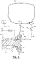
- Figure 2 shows part of a tractor rear axle, shown in cross-section, having an outer trumpet housing 32 within which a driveshaft 34 is supported by bearings 36.
- Driveshaft 34 terminates in a hub flange 38 to which a wheel disc 14a of wheel 14 is clamped by bolts 40 and a clamping ring 42.
- the wheel disc 14a carries the wheel rim 22 on which the pneumatic tyre 24 is mounted.
- a tyre inflation feed arrangement conveys compressed air from a compressor 44 (driven by prime mover 18) via one or more air control valves 46 mounted on the tractor to the rotating wheel 14 and hence via an air control valve 48 mounted on the wheel to the interior of the tyre 24 via lines 50 and 52.
- Control valves 46 are suitably solenoid control valves which are controlled by the control unit 30.
- Control valve 48 is a biased pressure controlled valve which opens the air flow from line 50 and thereby compressor 44 to line 52 and the interior of the tyre 24 when the control inlet 48c is charged with air via control line 54.
- control valve 48 To increase the air pressure in the tyre 24, air from the compressor 44 is supplied to control valve 48 via supply line 50. At the same time, the control inlet 48c of control valve 48 is charged with air via control line 54, so that the passage to line 52 and the interior of the tyre 24 is open. Thereby, pressure in the tyre 24 is increased.
- control inlet 48c of control valve 48 is charged with air via control line 54, so that supply line 50 is connected to the line 52 and hence the interior of the tyre 24.
- a control valve 46 is switched into a position so that the interior of the tyre is connected to the ambient environment so the tyre pressure inside the tyre 24 is decreased.
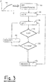
- a method for controlling the agricultural vehicle of Figures 1 and 2 will now be described with reference to the flow chart of Figure 3 which commences at step 100 with obtaining the slippage characteristic 98 for the used wheel rim and tyre combination.
- the slippage characteristic is determined empirically and relates the respective driving torque T at which the frictional coupling between driven wheel rim and tyre begins to slip for each of a range of tyre pressures P (or the respective tyre pressure P at which the frictional coupling between driven wheel rim and tyre begins to slip for each of a range of driving torque T values).
- the next step 102 is to determine the current tyre pressure P, from a pressure sensor associated with the tyre inflation system of Figure 2 .
- the current driving torque T is determined.
- a continuously variable transmission CVT
- the transmission output torque approximately equal to the wheel drive torque
- a continuously variable transmission CVT
- the torque may be derived from oil pressure in the hydrostatic circuit.
- the power is delivered by solely by hydraulic motors assigned to an axle of a vehicle or each wheel of a vehicle.
- the current driving torque T can be determined for each axle or wheel and thereby the T/P values indicating that slippage between tyre and rim is on the point of occurring can be stored in a characteristic 98 per axle or per wheel.
- a check is made as to whether the current T/P values indicate from the characteristic 98 that slippage between tyre and rim is on the point of occurring - that is to say if an "allowable point" for the tyre is to be exceeded. If the wheel drive torque is going below/higher than a particular level, for the tyre allowable point, the tyre pressure will increase/decrease automatically. In the method of Figure 3 , if the check at step 106 indicates no slip, then the process loops back to preceding step 104. If step 106 is affirmative for slipping, a further check step 108 identifies whether the tyre pressure P is at a maximum level, which maximum level may simply be specified for the tyre or may be modified by reference to the operating mode of the vehicle.
- step 108 If step 108 is affirmative for maximum pressure, then at step 110 the drive torque is limited or reduced to prevent slipping, following which the process reverts to step 104. If step 108 is negative for maximum pressure, then at step 112 the tyre pressure is increased (to increase the friction due to pressure between tyre 24 and rim 22; Fig. 2 ) and the process reverts to step 102.
- set points for correction may be sent to the driver.
- the tyre pressure adjustment according Figure 3 may be different for each axle or wheel. Similar, different T/P characteristics may be assigned to each axle of a vehicle due to tyre configuration, e.g. a tractor having different sized tyres on front and rear axle.
- the allowable point relation between wheel drive torque and tyre pressure is independent of traction power, axle load etc. If traction power/drag force or roll resisting forces/downhill-slope forces etc. (generally everything that influences the balance of power during transmission of forces between tyres and ground) is changing, the calculated characteristic pair of values of wheel drive torque/tyre pressure stays the same, because only drive torque is relevant for the transmission between tyre and rim and not how that force (circumferential force at the contact point of tyre/ground) distributes on traction power, roll resisting power, downhill-slope force etc.
- the control system of the invention may be further configured to account for the allowable point relation between wheel drive torque and tyre pressure being influenced by further parameters.
- the frictional coupling between driven wheel rim and tyre may also depend on the temperature of the tyre. If the tyre temperature increases, the tyre becomes more elastic so that the contact areas between tyre and rim are less tensioned/biased/preloaded. Initially, the tyre is heated up with increasing ambient temperature, which temperature value is available to the control system being already determined for other purposes such as the cab air conditioning. As mentioned above, the tyres are also heated up, especially at high speed, because of higher flexing work, so the vehicle speed may be a further parameter supplied to the control system. Alternatively to the indirect determination described above the the tyre temperature may be measured directly by a temperature senor in the tyre body.
- T/P values for various tyre temperatures or, if indirectly determined, for various ambient temperatures or various vehicle speeds.
- Other influencing parameters affecting the characteristic (or resulting in a family of characteristics) may also be captured.
- the property of tyres changes during lifetime, so the operating time of a tyre may be monitored to provide a further characteristic variation depending on the operating time.
- the vehicle having a motive power unit providing a driving torque to at least one driven wheel and having at least one tyre frictionally coupled with the periphery of the driven wheel.
- a vehicle operating parameter is controlled in dependence on the driving torque and a slippage characteristic relating the respective driving torque at which the frictional coupling between driven wheel and tyre begins to slip for a range of vehicle operating parameter values.
- the operating parameter is suitably a tyre pressure, and the control may involve reducing driving torque or increasing pressure to prevent slipping.
Landscapes
- Engineering & Computer Science (AREA)
- Mechanical Engineering (AREA)
- Chemical & Material Sciences (AREA)
- Combustion & Propulsion (AREA)
- Transportation (AREA)
- Life Sciences & Earth Sciences (AREA)
- Soil Sciences (AREA)
- Environmental Sciences (AREA)
- Automation & Control Theory (AREA)
- Tires In General (AREA)
- Arrangement And Driving Of Transmission Devices (AREA)
Claims (15)
- Steuer- und/oder Regelsystem (30) für ein landwirtschaftliches Fahrzeug (10) mit einer Antriebseinheit, die mindestens einem angetriebenen Rad (14) ein Antriebsmoment (T) bereitstellt, wobei das Rad (14) eine Peripherie mit einer Felge (22) und mindestens einen Luftreifen (24) aufweist, der auf der Felge montiert und reibschlüssig mit der Felge des mindestens einen angetriebenen Rads verbunden ist;
wobei der Luftreifen einen Luftdruck (P) aufweist;
wobei das Steuer- und/oder Regelsystem dazu angeordnet ist, den Luftdruck in Abhängigkeit von einem Leistungsmesswert des Fahrzeugs und einem Schlupfkennwert (98) des Luftreifens zu steuern und/oder zu regeln; dadurch gekennzeichnet, dass
der Leistungsmesswert ein Messwert des Antriebsmoments ist und der Schlupfkennwert das jeweilige Antriebsmoment betrifft, bei dem die reibschlüssige Verbindung zwischen dem mindestens einen angetriebenen Rad und dem Luftreifen für jeden einer Mehrzahl von Luftdruckwerten Schlupf zu haben beginnt. - Steuer- und/oder Regelsystem nach Anspruch 1, wobei das Steuer- und/oder Regelsystem ein Speicherbauteil aufweist und der Schlupfkennwert eine in dem Speicherbauteil gespeicherte Kurve ist.
- Steuer- und/oder Regelsystem nach Anspruch 2, wobei die Kurve durch Betreiben des Fahrzeugs bei jedem der Mehrzahl von Luftdruckwerten und, für jeden der Luftdruckwerte, Erhöhen des Antriebsmoments und Erfassen des Antriebsmomentwerts erzeugt wird, an dem Schlupf zwischen dem mindestens einen angetriebenen Rad und dem Luftreifen beginnt,.
- Steuer- und/oder Regelsystem nach mindestens einem der Ansprüche 1 bis 3, wobei der Antriebsmomentmesswert aus dem Öldruck in einem hydrostatischen Kreislauf mit mindestens einer durch die Antriebseinheit angetriebenen hydraulischen Pumpe und mindestens einem mit dem mindestens einen angetriebenen Rad verbundenen hydraulischen Motor berechnet wird.
- Steuer- und/oder Regelsystem nach Anspruch 4, wobei der hydrostatische Kreislauf ein hydrostatischer Zweig eines hydromechanischen Leistungsverzweigungsgetriebes ist.
- Steuer- und/oder Regelsystem nach Anspruch 4, wobei der hydrostatische Kreislauf ein hydrostatischen Zweig mit mindestens einem in Antriebsverbindung mit einem in den Boden eingreifenden Bauteil stehenden hydraulischen Motor ist.
- Steuer- und/oder Regelsystem nach Anspruch 4, wobei der hydrostatischen Kreislauf ein hydrostatischer Zweig mit mindestens einem in Antriebsverbindung mit einer Fahrzeugachse, die in Antriebsverbindung mit mindestens zwei in den Boden eingreifenden Bauteilen steht, stehenden hydraulischen Motor ist.
- Steuer- und/oder Regelsystem nach mindestens einem der Ansprüche 1 bis 3, wobei die Antriebseinheit einen Elektromotor aufweist und wobei das Antriebsmoment aus der Stromaufnahme des Elektromotors berechnet wird.
- Steuer- und/oder Regelsystem nach mindestens einem der Ansprüche 1 bis 8, für ein Fahrzeug mit mindestens zwei Luftreifen, die jeweils auf einer Felge eines jeweiligen angetriebenen Rads auf einer Fahrzeugachse montiert sind, wobei das Steuer- und/oder Regelsystem dazu betreibbar ist, den Luftdruck in einem ersten Reifen unabhängig vom dem Luftdruck in einem weiteren Reifen zu variieren.
- Steuer- und/oder Regelsystem nach mindestens einem der vorhergehenden Ansprüche, das weiterhin dazu angeordnet ist, die Luftdrucksteuerung und/oder -regelung unter Bezug auf einen die Temperatur anzeigenden Wert anzupassen.
- Steuer- und/oder Regelsystem nach mindestens einem der vorhergehenden Ansprüche, wobei der Schlupfkennwert unter Bezug auf einen oder mehrere der folgenden Werte angepasst werden kann: Reifentemperatur, Umgebungstemperatur, Fahrzeuggeschwindigkeit und Reifenbetriebsdauer.
- Landwirtschaftliches Fahrzeug mit einem Steuer- und/oder Regelsystem nach mindestens einem der vorhergehenden Ansprüche.
- Verfahren zum Steuern und/oder Regeln eines landwirtschaftlichen Fahrzeugs mit einer Antriebseinheit, die mindestens einem angetriebenen Rad ein Antriebsmoment bereitstellt, wobei das Rad eine Peripherie mit einer Felge und mindestens einen reibschlüssig mit der Felge des mindestens einen angetriebenen Rads verbundenen Luftreifen aufweist, wobei der Luftreifen einen Luftdruck aufweist und wobei das Verfahren das Steuern und/oder Regeln des Luftdrucks in Abhängigkeit von einem Leistungsmesswert des Fahrzeugs und einem Schlupfkennwert des Luftreifens aufweist; dadurch gekennzeichnet, dass
der Leistungsmesswert ein Messwert des Antriebsmoments ist und der Schlupfkennwert das jeweilige Antriebsmoment betrifft, bei dem die reibschlüssige Verbindung zwischen dem mindestens einen angetriebenen Rad und dem Luftreifen für jeden einer Mehrzahl von Luftdruckwerten Schlupf zu haben beginnt. - Verfahren nach Anspruch 13, wobei das landwirtschaftliche Fahrzeug eine durch die Antriebseinheit angetriebene kontinuierlich veränderbare Übersetzung aufweist, wobei das Verfahren weiterhin das Berechnen des Antriebsmoments aus einem oder mehreren gemessenen Betriebsparametern der Übersetzung aufweist.
- Verfahren nach Anspruch 13 oder 14, weiterhin mit dem Erzeugen einer Kurve des Schlupfkennwerts durch Betreiben des Fahrzeugs bei jedem einer Mehrzahl von Luftdruckwerten und, für jeden Luftdruckwert, Erhöhen des Antriebsmoments und Erfassen des Antriebsmomentwerts, bei dem ein Schlupf zwischen dem Antriebsrad und dem Luftreifen beginnt.
Applications Claiming Priority (2)
| Application Number | Priority Date | Filing Date | Title |
|---|---|---|---|
| GBGB1420529.8A GB201420529D0 (en) | 2014-11-19 | 2014-11-19 | Vehicle wheel slippage control |
| PCT/EP2015/067685 WO2016078782A1 (en) | 2014-11-19 | 2015-07-31 | Vehicle wheel slippage control |
Publications (2)
| Publication Number | Publication Date |
|---|---|
| EP3220732A1 EP3220732A1 (de) | 2017-09-27 |
| EP3220732B1 true EP3220732B1 (de) | 2019-02-20 |
Family
ID=52248574
Family Applications (1)
| Application Number | Title | Priority Date | Filing Date |
|---|---|---|---|
| EP15745473.7A Active EP3220732B1 (de) | 2014-11-19 | 2015-07-31 | Schlupfsteuerung eines fahrzeugrades |
Country Status (4)
| Country | Link |
|---|---|
| US (1) | US10023193B2 (de) |
| EP (1) | EP3220732B1 (de) |
| GB (1) | GB201420529D0 (de) |
| WO (1) | WO2016078782A1 (de) |
Families Citing this family (10)
| Publication number | Priority date | Publication date | Assignee | Title |
|---|---|---|---|---|
| DE102016218841A1 (de) * | 2016-09-29 | 2018-03-29 | Schaeffler Technologies AG & Co. KG | Getriebe mit Drehmomentenmessvorrichtung |
| WO2018140248A1 (en) * | 2017-01-24 | 2018-08-02 | Bridgestone Americas Tire Operations, Llc | Multi-chambered wheel assembly for rapid tire inflation |
| CN107650589A (zh) * | 2017-09-13 | 2018-02-02 | 上海志工电子科技有限公司 | 一种基于速度传感器的高频回路胎压监测系统 |
| PL3483024T3 (pl) * | 2017-11-10 | 2020-09-07 | Exel Industries | Pojazd i odpowiednie zastosowanie |
| US11528836B2 (en) | 2019-11-22 | 2022-12-20 | Cnh Industrial America Llc | System and method for sequentially controlling agricultural implement ground-engaging tools |
| US12344047B2 (en) * | 2020-10-29 | 2025-07-01 | William Pamphile | Automatic air tire technology system |
| CN112810601B (zh) * | 2020-12-29 | 2022-03-01 | 北京农业智能装备技术研究中心 | 一种适用于无人驾驶农机的行进速度调控方法及系统 |
| JP7517192B2 (ja) * | 2021-02-12 | 2024-07-17 | トヨタ自動車株式会社 | 車両の走行支援システム |
| DE102021120759A1 (de) | 2021-08-10 | 2023-02-16 | Claas Tractor Sas | Verfahren zur Messung einer absoluten Arbeitshöhe mehrerer landwirtschaftlicher Anbaugeräte |
| DE102021120813A1 (de) | 2021-08-10 | 2023-02-16 | Claas Tractor Sas | Verfahren zur Regelung eines Heckkrafthebers einer landwirtschaftlichen Arbeitsmaschine |
Citations (1)
| Publication number | Priority date | Publication date | Assignee | Title |
|---|---|---|---|---|
| US20090030581A1 (en) * | 2007-07-27 | 2009-01-29 | Manfred Pollklas | Agricultural working machine |
Family Cites Families (13)
| Publication number | Priority date | Publication date | Assignee | Title |
|---|---|---|---|---|
| DE4242109C2 (de) | 1992-12-14 | 1995-05-04 | Dietrich Gerhard Ellsaeser | Vorrichtung zur Ermittlung des auf die Reifen eines Landfahrzeuges einwirkenden Bodenwiderstandes |
| DE10016435B4 (de) * | 2000-04-01 | 2014-03-13 | Deere & Company | Lüftungseinrichtung für ein landwirtschaftliches Fahrzeug |
| GB0130673D0 (en) * | 2001-12-21 | 2002-02-06 | New Holland Uk Ltd | Tractor/implement combination control methods and apparatuses |
| US8164293B2 (en) * | 2009-09-08 | 2012-04-24 | Hoffman Enclosures, Inc. | Method of controlling a motor |
| US9248705B2 (en) | 2010-10-04 | 2016-02-02 | Agco International Gmbh | Rotary joint |
| DE102010053264A1 (de) * | 2010-12-02 | 2012-06-06 | Wabco Gmbh | Verfahren zur Steuerung des Druckausgleichs bei einem Fahrwerk mit einer Antriebsachse und einer Schleppachse |
| US8985250B1 (en) * | 2010-12-14 | 2015-03-24 | Camoplast Solideal Inc. | Track drive mode management system and methods |
| US20130054078A1 (en) | 2011-08-17 | 2013-02-28 | Noel Wayne Anderson | Dynamic traction adjustment |
| DE102011085041B4 (de) * | 2011-10-21 | 2026-04-23 | Deere & Company | Landwirtschaftliches Fahrzeug |
| JP5427868B2 (ja) | 2011-10-21 | 2014-02-26 | 住友ゴム工業株式会社 | タイヤ空気圧低下検出方法、装置及びプログラム |
| DE102011085040A1 (de) * | 2011-10-21 | 2013-04-25 | Deere & Company | Landwirtschaftliches Fahrzeug |
| US9296263B2 (en) | 2011-12-23 | 2016-03-29 | Prasad Muthukumar | Smart active tyre pressure optimising system |
| US20140069092A1 (en) * | 2012-09-07 | 2014-03-13 | Caterpillar, Inc. | Traction Control System for a Hydrostatic Drive |
-
2014
- 2014-11-19 GB GBGB1420529.8A patent/GB201420529D0/en not_active Ceased
-
2015
- 2015-07-31 US US15/528,194 patent/US10023193B2/en active Active
- 2015-07-31 EP EP15745473.7A patent/EP3220732B1/de active Active
- 2015-07-31 WO PCT/EP2015/067685 patent/WO2016078782A1/en not_active Ceased
Patent Citations (1)
| Publication number | Priority date | Publication date | Assignee | Title |
|---|---|---|---|---|
| US20090030581A1 (en) * | 2007-07-27 | 2009-01-29 | Manfred Pollklas | Agricultural working machine |
Also Published As
| Publication number | Publication date |
|---|---|
| US10023193B2 (en) | 2018-07-17 |
| EP3220732A1 (de) | 2017-09-27 |
| GB201420529D0 (en) | 2014-12-31 |
| US20170313318A1 (en) | 2017-11-02 |
| WO2016078782A1 (en) | 2016-05-26 |
Similar Documents
| Publication | Publication Date | Title |
|---|---|---|
| EP3220732B1 (de) | Schlupfsteuerung eines fahrzeugrades | |
| EP3643152B1 (de) | Steuersystem für einen traktor | |
| US9095089B2 (en) | Tractor control/display systems | |
| US9255639B2 (en) | Electronic control for the drive unit of a vehicle | |
| US20160039480A1 (en) | Tractor control system | |
| EP2984914B1 (de) | Fahrzeugsteuerungssystem | |
| RU2633559C2 (ru) | Сельскохозяйственная рабочая система | |
| RU2472335C2 (ru) | Рабочая сельхозмашина | |
| US20160016470A1 (en) | Tractor control/display systems | |
| US10752188B2 (en) | System and method for reducing fuel consumption of a work vehicle based on estimated fan-based and/or alternator-based power losses | |
| EA018480B1 (ru) | Сельскохозяйственное транспортное средство с регулируемым тяговым усилием | |
| US20160082789A1 (en) | Method and system for reducing vehicle oscillations | |
| US7555903B2 (en) | Tire pressure regulating system | |
| EP3362708B1 (de) | Antriebsstrang eines landwirtschaftlichen fahrzeugs | |
| US20170253094A1 (en) | System for tire pressure monitoring for a utility vehicle | |
| US10793092B2 (en) | System and method for reducing fuel consumption of a work vehicle based on estimated parastic power losses | |
| US20200255015A1 (en) | Method for operating a drive train of a vehicle | |
| US9597950B2 (en) | Traction system and a method for controlling said traction system | |
| JP6844433B2 (ja) | 作業車両 | |
| JP7060122B2 (ja) | 作業車両 | |
| KR20200101554A (ko) | 농용 트랙터의 타이어 공기압 조절장치 | |
| EP4572967A1 (de) | Fahrzeug mit steuerbarer kupplung zwischen vorder- und hinterachse und verfahren zur steuerung des variablen kupplungseinrückverhältnisses der kupplung |
Legal Events
| Date | Code | Title | Description |
|---|---|---|---|
| STAA | Information on the status of an ep patent application or granted ep patent |
Free format text: STATUS: THE INTERNATIONAL PUBLICATION HAS BEEN MADE |
|
| PUAI | Public reference made under article 153(3) epc to a published international application that has entered the european phase |
Free format text: ORIGINAL CODE: 0009012 |
|
| STAA | Information on the status of an ep patent application or granted ep patent |
Free format text: STATUS: REQUEST FOR EXAMINATION WAS MADE |
|
| 17P | Request for examination filed |
Effective date: 20170619 |
|
| AK | Designated contracting states |
Kind code of ref document: A1 Designated state(s): AL AT BE BG CH CY CZ DE DK EE ES FI FR GB GR HR HU IE IS IT LI LT LU LV MC MK MT NL NO PL PT RO RS SE SI SK SM TR |
|
| AX | Request for extension of the european patent |
Extension state: BA ME |
|
| DAV | Request for validation of the european patent (deleted) | ||
| DAX | Request for extension of the european patent (deleted) | ||
| STAA | Information on the status of an ep patent application or granted ep patent |
Free format text: STATUS: EXAMINATION IS IN PROGRESS |
|
| 17Q | First examination report despatched |
Effective date: 20180424 |
|
| GRAP | Despatch of communication of intention to grant a patent |
Free format text: ORIGINAL CODE: EPIDOSNIGR1 |
|
| STAA | Information on the status of an ep patent application or granted ep patent |
Free format text: STATUS: GRANT OF PATENT IS INTENDED |
|
| INTG | Intention to grant announced |
Effective date: 20181129 |
|
| GRAS | Grant fee paid |
Free format text: ORIGINAL CODE: EPIDOSNIGR3 |
|
| GRAA | (expected) grant |
Free format text: ORIGINAL CODE: 0009210 |
|
| STAA | Information on the status of an ep patent application or granted ep patent |
Free format text: STATUS: THE PATENT HAS BEEN GRANTED |
|
| AK | Designated contracting states |
Kind code of ref document: B1 Designated state(s): AL AT BE BG CH CY CZ DE DK EE ES FI FR GB GR HR HU IE IS IT LI LT LU LV MC MK MT NL NO PL PT RO RS SE SI SK SM TR |
|
| REG | Reference to a national code |
Ref country code: GB Ref legal event code: FG4D |
|
| REG | Reference to a national code |
Ref country code: CH Ref legal event code: EP |
|
| REG | Reference to a national code |
Ref country code: DE Ref legal event code: R096 Ref document number: 602015024899 Country of ref document: DE |
|
| REG | Reference to a national code |
Ref country code: AT Ref legal event code: REF Ref document number: 1096999 Country of ref document: AT Kind code of ref document: T Effective date: 20190315 |
|
| REG | Reference to a national code |
Ref country code: IE Ref legal event code: FG4D |
|
| REG | Reference to a national code |
Ref country code: LT Ref legal event code: MG4D |
|
| REG | Reference to a national code |
Ref country code: NL Ref legal event code: MP Effective date: 20190220 |
|
| PG25 | Lapsed in a contracting state [announced via postgrant information from national office to epo] |
Ref country code: PT Free format text: LAPSE BECAUSE OF FAILURE TO SUBMIT A TRANSLATION OF THE DESCRIPTION OR TO PAY THE FEE WITHIN THE PRESCRIBED TIME-LIMIT Effective date: 20190620 Ref country code: FI Free format text: LAPSE BECAUSE OF FAILURE TO SUBMIT A TRANSLATION OF THE DESCRIPTION OR TO PAY THE FEE WITHIN THE PRESCRIBED TIME-LIMIT Effective date: 20190220 Ref country code: NO Free format text: LAPSE BECAUSE OF FAILURE TO SUBMIT A TRANSLATION OF THE DESCRIPTION OR TO PAY THE FEE WITHIN THE PRESCRIBED TIME-LIMIT Effective date: 20190520 Ref country code: SE Free format text: LAPSE BECAUSE OF FAILURE TO SUBMIT A TRANSLATION OF THE DESCRIPTION OR TO PAY THE FEE WITHIN THE PRESCRIBED TIME-LIMIT Effective date: 20190220 Ref country code: LT Free format text: LAPSE BECAUSE OF FAILURE TO SUBMIT A TRANSLATION OF THE DESCRIPTION OR TO PAY THE FEE WITHIN THE PRESCRIBED TIME-LIMIT Effective date: 20190220 |
|
| PG25 | Lapsed in a contracting state [announced via postgrant information from national office to epo] |
Ref country code: HR Free format text: LAPSE BECAUSE OF FAILURE TO SUBMIT A TRANSLATION OF THE DESCRIPTION OR TO PAY THE FEE WITHIN THE PRESCRIBED TIME-LIMIT Effective date: 20190220 Ref country code: RS Free format text: LAPSE BECAUSE OF FAILURE TO SUBMIT A TRANSLATION OF THE DESCRIPTION OR TO PAY THE FEE WITHIN THE PRESCRIBED TIME-LIMIT Effective date: 20190220 Ref country code: BG Free format text: LAPSE BECAUSE OF FAILURE TO SUBMIT A TRANSLATION OF THE DESCRIPTION OR TO PAY THE FEE WITHIN THE PRESCRIBED TIME-LIMIT Effective date: 20190520 Ref country code: NL Free format text: LAPSE BECAUSE OF FAILURE TO SUBMIT A TRANSLATION OF THE DESCRIPTION OR TO PAY THE FEE WITHIN THE PRESCRIBED TIME-LIMIT Effective date: 20190220 Ref country code: GR Free format text: LAPSE BECAUSE OF FAILURE TO SUBMIT A TRANSLATION OF THE DESCRIPTION OR TO PAY THE FEE WITHIN THE PRESCRIBED TIME-LIMIT Effective date: 20190521 Ref country code: IS Free format text: LAPSE BECAUSE OF FAILURE TO SUBMIT A TRANSLATION OF THE DESCRIPTION OR TO PAY THE FEE WITHIN THE PRESCRIBED TIME-LIMIT Effective date: 20190620 Ref country code: LV Free format text: LAPSE BECAUSE OF FAILURE TO SUBMIT A TRANSLATION OF THE DESCRIPTION OR TO PAY THE FEE WITHIN THE PRESCRIBED TIME-LIMIT Effective date: 20190220 |
|
| REG | Reference to a national code |
Ref country code: AT Ref legal event code: MK05 Ref document number: 1096999 Country of ref document: AT Kind code of ref document: T Effective date: 20190220 |
|
| PG25 | Lapsed in a contracting state [announced via postgrant information from national office to epo] |
Ref country code: EE Free format text: LAPSE BECAUSE OF FAILURE TO SUBMIT A TRANSLATION OF THE DESCRIPTION OR TO PAY THE FEE WITHIN THE PRESCRIBED TIME-LIMIT Effective date: 20190220 Ref country code: SK Free format text: LAPSE BECAUSE OF FAILURE TO SUBMIT A TRANSLATION OF THE DESCRIPTION OR TO PAY THE FEE WITHIN THE PRESCRIBED TIME-LIMIT Effective date: 20190220 Ref country code: DK Free format text: LAPSE BECAUSE OF FAILURE TO SUBMIT A TRANSLATION OF THE DESCRIPTION OR TO PAY THE FEE WITHIN THE PRESCRIBED TIME-LIMIT Effective date: 20190220 Ref country code: AL Free format text: LAPSE BECAUSE OF FAILURE TO SUBMIT A TRANSLATION OF THE DESCRIPTION OR TO PAY THE FEE WITHIN THE PRESCRIBED TIME-LIMIT Effective date: 20190220 Ref country code: RO Free format text: LAPSE BECAUSE OF FAILURE TO SUBMIT A TRANSLATION OF THE DESCRIPTION OR TO PAY THE FEE WITHIN THE PRESCRIBED TIME-LIMIT Effective date: 20190220 Ref country code: CZ Free format text: LAPSE BECAUSE OF FAILURE TO SUBMIT A TRANSLATION OF THE DESCRIPTION OR TO PAY THE FEE WITHIN THE PRESCRIBED TIME-LIMIT Effective date: 20190220 Ref country code: ES Free format text: LAPSE BECAUSE OF FAILURE TO SUBMIT A TRANSLATION OF THE DESCRIPTION OR TO PAY THE FEE WITHIN THE PRESCRIBED TIME-LIMIT Effective date: 20190220 |
|
| REG | Reference to a national code |
Ref country code: DE Ref legal event code: R097 Ref document number: 602015024899 Country of ref document: DE |
|
| PG25 | Lapsed in a contracting state [announced via postgrant information from national office to epo] |
Ref country code: SM Free format text: LAPSE BECAUSE OF FAILURE TO SUBMIT A TRANSLATION OF THE DESCRIPTION OR TO PAY THE FEE WITHIN THE PRESCRIBED TIME-LIMIT Effective date: 20190220 Ref country code: PL Free format text: LAPSE BECAUSE OF FAILURE TO SUBMIT A TRANSLATION OF THE DESCRIPTION OR TO PAY THE FEE WITHIN THE PRESCRIBED TIME-LIMIT Effective date: 20190220 |
|
| PLBE | No opposition filed within time limit |
Free format text: ORIGINAL CODE: 0009261 |
|
| STAA | Information on the status of an ep patent application or granted ep patent |
Free format text: STATUS: NO OPPOSITION FILED WITHIN TIME LIMIT |
|
| PG25 | Lapsed in a contracting state [announced via postgrant information from national office to epo] |
Ref country code: AT Free format text: LAPSE BECAUSE OF FAILURE TO SUBMIT A TRANSLATION OF THE DESCRIPTION OR TO PAY THE FEE WITHIN THE PRESCRIBED TIME-LIMIT Effective date: 20190220 |
|
| 26N | No opposition filed |
Effective date: 20191121 |
|
| PG25 | Lapsed in a contracting state [announced via postgrant information from national office to epo] |
Ref country code: MC Free format text: LAPSE BECAUSE OF FAILURE TO SUBMIT A TRANSLATION OF THE DESCRIPTION OR TO PAY THE FEE WITHIN THE PRESCRIBED TIME-LIMIT Effective date: 20190220 Ref country code: SI Free format text: LAPSE BECAUSE OF FAILURE TO SUBMIT A TRANSLATION OF THE DESCRIPTION OR TO PAY THE FEE WITHIN THE PRESCRIBED TIME-LIMIT Effective date: 20190220 |
|
| REG | Reference to a national code |
Ref country code: CH Ref legal event code: PL |
|
| GBPC | Gb: european patent ceased through non-payment of renewal fee |
Effective date: 20190731 |
|
| PG25 | Lapsed in a contracting state [announced via postgrant information from national office to epo] |
Ref country code: TR Free format text: LAPSE BECAUSE OF FAILURE TO SUBMIT A TRANSLATION OF THE DESCRIPTION OR TO PAY THE FEE WITHIN THE PRESCRIBED TIME-LIMIT Effective date: 20190220 |
|
| REG | Reference to a national code |
Ref country code: BE Ref legal event code: MM Effective date: 20190731 |
|
| PG25 | Lapsed in a contracting state [announced via postgrant information from national office to epo] |
Ref country code: GB Free format text: LAPSE BECAUSE OF NON-PAYMENT OF DUE FEES Effective date: 20190731 |
|
| PG25 | Lapsed in a contracting state [announced via postgrant information from national office to epo] |
Ref country code: BE Free format text: LAPSE BECAUSE OF NON-PAYMENT OF DUE FEES Effective date: 20190731 Ref country code: LU Free format text: LAPSE BECAUSE OF NON-PAYMENT OF DUE FEES Effective date: 20190731 Ref country code: CH Free format text: LAPSE BECAUSE OF NON-PAYMENT OF DUE FEES Effective date: 20190731 Ref country code: LI Free format text: LAPSE BECAUSE OF NON-PAYMENT OF DUE FEES Effective date: 20190731 |
|
| PG25 | Lapsed in a contracting state [announced via postgrant information from national office to epo] |
Ref country code: IE Free format text: LAPSE BECAUSE OF NON-PAYMENT OF DUE FEES Effective date: 20190731 |
|
| PG25 | Lapsed in a contracting state [announced via postgrant information from national office to epo] |
Ref country code: CY Free format text: LAPSE BECAUSE OF FAILURE TO SUBMIT A TRANSLATION OF THE DESCRIPTION OR TO PAY THE FEE WITHIN THE PRESCRIBED TIME-LIMIT Effective date: 20190220 |
|
| PG25 | Lapsed in a contracting state [announced via postgrant information from national office to epo] |
Ref country code: MT Free format text: LAPSE BECAUSE OF FAILURE TO SUBMIT A TRANSLATION OF THE DESCRIPTION OR TO PAY THE FEE WITHIN THE PRESCRIBED TIME-LIMIT Effective date: 20190220 Ref country code: HU Free format text: LAPSE BECAUSE OF FAILURE TO SUBMIT A TRANSLATION OF THE DESCRIPTION OR TO PAY THE FEE WITHIN THE PRESCRIBED TIME-LIMIT; INVALID AB INITIO Effective date: 20150731 |
|
| PGFP | Annual fee paid to national office [announced via postgrant information from national office to epo] |
Ref country code: IT Payment date: 20210726 Year of fee payment: 7 |
|
| PG25 | Lapsed in a contracting state [announced via postgrant information from national office to epo] |
Ref country code: MK Free format text: LAPSE BECAUSE OF FAILURE TO SUBMIT A TRANSLATION OF THE DESCRIPTION OR TO PAY THE FEE WITHIN THE PRESCRIBED TIME-LIMIT Effective date: 20190220 |
|
| P01 | Opt-out of the competence of the unified patent court (upc) registered |
Effective date: 20230518 |
|
| PG25 | Lapsed in a contracting state [announced via postgrant information from national office to epo] |
Ref country code: IT Free format text: LAPSE BECAUSE OF NON-PAYMENT OF DUE FEES Effective date: 20220731 |
|
| PGFP | Annual fee paid to national office [announced via postgrant information from national office to epo] |
Ref country code: DE Payment date: 20250722 Year of fee payment: 11 |
|
| PGFP | Annual fee paid to national office [announced via postgrant information from national office to epo] |
Ref country code: FR Payment date: 20250725 Year of fee payment: 11 |