EP3220733B1 - Machine de récolte avec systeme de controle de la rotation d'un convoyeur de déchargement - Google Patents
Machine de récolte avec systeme de controle de la rotation d'un convoyeur de déchargement Download PDFInfo
- Publication number
- EP3220733B1 EP3220733B1 EP15802191.5A EP15802191A EP3220733B1 EP 3220733 B1 EP3220733 B1 EP 3220733B1 EP 15802191 A EP15802191 A EP 15802191A EP 3220733 B1 EP3220733 B1 EP 3220733B1
- Authority
- EP
- European Patent Office
- Prior art keywords
- conveyor
- harvesting machine
- machine according
- unloading
- movement range
- Prior art date
- Legal status (The legal status is an assumption and is not a legal conclusion. Google has not performed a legal analysis and makes no representation as to the accuracy of the status listed.)
- Not-in-force
Links
- 238000003306 harvesting Methods 0.000 title claims description 16
- 238000004891 communication Methods 0.000 claims description 5
- 230000004044 response Effects 0.000 claims description 4
- 230000003247 decreasing effect Effects 0.000 claims description 2
- 241001124569 Lycaenidae Species 0.000 description 5
- 238000000034 method Methods 0.000 description 4
- 238000010586 diagram Methods 0.000 description 3
- 230000009471 action Effects 0.000 description 2
- 239000004459 forage Substances 0.000 description 2
- 240000000111 Saccharum officinarum Species 0.000 description 1
- 235000007201 Saccharum officinarum Nutrition 0.000 description 1
- 230000009286 beneficial effect Effects 0.000 description 1
- 238000004590 computer program Methods 0.000 description 1
- 238000010276 construction Methods 0.000 description 1
- 230000000694 effects Effects 0.000 description 1
- 210000002310 elbow joint Anatomy 0.000 description 1
- 230000005611 electricity Effects 0.000 description 1
- 238000005516 engineering process Methods 0.000 description 1
- 230000006870 function Effects 0.000 description 1
- 230000010354 integration Effects 0.000 description 1
- 238000012986 modification Methods 0.000 description 1
- 230000004048 modification Effects 0.000 description 1
- 230000003287 optical effect Effects 0.000 description 1
- 230000008569 process Effects 0.000 description 1
- 230000009467 reduction Effects 0.000 description 1
- 239000004065 semiconductor Substances 0.000 description 1
Images

Classifications
-
- A—HUMAN NECESSITIES
- A01—AGRICULTURE; FORESTRY; ANIMAL HUSBANDRY; HUNTING; TRAPPING; FISHING
- A01D—HARVESTING; MOWING
- A01D41/00—Combines, i.e. harvesters or mowers combined with threshing devices
- A01D41/12—Details of combines
- A01D41/1208—Tanks for grain or chaff
- A01D41/1217—Unloading mechanisms
-
- A—HUMAN NECESSITIES
- A01—AGRICULTURE; FORESTRY; ANIMAL HUSBANDRY; HUNTING; TRAPPING; FISHING
- A01D—HARVESTING; MOWING
- A01D43/00—Mowers combined with apparatus performing additional operations while mowing
- A01D43/06—Mowers combined with apparatus performing additional operations while mowing with means for collecting, gathering or loading mown material
- A01D43/063—Mowers combined with apparatus performing additional operations while mowing with means for collecting, gathering or loading mown material in or into a container carried by the mower; Containers therefor
- A01D43/0635—Mowers combined with apparatus performing additional operations while mowing with means for collecting, gathering or loading mown material in or into a container carried by the mower; Containers therefor with emptying means
-
- A—HUMAN NECESSITIES
- A01—AGRICULTURE; FORESTRY; ANIMAL HUSBANDRY; HUNTING; TRAPPING; FISHING
- A01D—HARVESTING; MOWING
- A01D61/00—Elevators or conveyors for binders or combines
-
- B—PERFORMING OPERATIONS; TRANSPORTING
- B65—CONVEYING; PACKING; STORING; HANDLING THIN OR FILAMENTARY MATERIAL
- B65G—TRANSPORT OR STORAGE DEVICES, e.g. CONVEYORS FOR LOADING OR TIPPING, SHOP CONVEYOR SYSTEMS OR PNEUMATIC TUBE CONVEYORS
- B65G33/00—Screw or rotary spiral conveyors
- B65G33/24—Details
Definitions
- the invention relates to unloading conveyors fitted to self-propelled harvesting machines, the conveyors being pivotable between a stowed, generally longitudinal, position and a deployed, generally transverse, position.
- the invention relates to a control system for controlling the movement of the conveyor between the stowed and deployed positions.
- Self-propelled harvesting machines include, by way of example, combine harvesters and forage harvesters, both including an elongate unloading conveyor that is typically moveable around a pivot axis through a movement range between a first, stowed, position and a second, deployed, position.
- the conveyor In the deployed position the conveyor extends generally transverse to the forward direction of travel and crop is discharged by the conveyor into a cart or trailer hauled alongside. Due to the excessive width when in the deployed position, the conveyor is swung around the pivot axis into the stowed position for transport wherein the axis of the conveyor is generally parallel to the longitudinal axis of the machine.
- Movement of the unloading conveyor is normally brought about by an actuator connected between the harvester frame and the conveyor.
- a user interface typically in the form of a pair of press-buttons or a rocker switch, allows a driver to issue commands to a controller in communication with the actuator for swinging the conveyor within the movement range as the operator desires.
- the operator may fine-tune the position of the conveyor within a narrow range of angles so as to 'top-off' the trailer.
- the conveyor is often swung into the stowed position to minimise the risk of collision with field objects such as electricity pylons. This stowing action requires the operator to maintain pressure on the associated button for a period in the region of 13 seconds.
- the harvesting operation does not generally cease during unloading. Therefore, the operator is required to monitor and control the unloading process whilst also maintaining attention on the harvesting operation.
- US-A-2013/0096782 discloses a control method for an unloading system wherein a user interface device controls the pivoting of an unloading tube when an auger is disengaged, whereas the user interface device controls the pivoting of a spout when the auger is engaged.
- an unloading conveyor swing control system comprising an unloading conveyor fitted to a self-propelled harvesting machine, the conveyor being moveable around a pivot axis through a movement range between a first, stowed, position and a second position, an actuator connected to the conveyor and arranged to move the conveyor throughout the movement range, a sensor configured to sense an angular position of the conveyor within the movement range and generate a representative position signal, a user interface device for receiving user-commands to move the conveyor, and a controller in communication with the sensor, the actuator and the user interface device, wherein the conveyor is automatically moved into the first position in response to said angular position falling below a predetermined threshold angle.
- the invention advantageously removes the need for the operator to maintain pressure on the associated button to stow the conveyor once the angular position has fallen below a predetermined angle.
- the operator can release the associated button (or user interface device) and return his focus to the harvesting task in hand.
- the invention involves the recognition that once the operator has swung the conveyor beyond the normal range of 'topping off' angles then it can reasonably be assumed that the operator wishes to stow the conveyor. Therefore, the invention provides that the controller automatically assumes the stowing operation allowing the operator to release the associated button.
- the range of movement of the conveyor around the pivot axis is generally around or greater than 90 degrees, wherein, at one extreme, the conveyor is in the stowed position with its axis generally aligned with the longitudinal axis of the harvester and, at the other extreme, the conveyor is forward of transverse, or over-centre, at an angle of around 105 degrees to the stowed position.
- An operating, or unloading, range may be defined between the threshold angle and the second position, wherein the second position equates to the aforementioned over-centre position.
- the operator may command movement, of the conveyor within the operating range without the controller automatically taking control.
- movement of the conveyor is directly attributed to operation of the associated buttons or rocker switch.
- the threshold angle, and thus the operating range is preferably user-adjustable.
- this allows the operator at the start of harvesting to enter the angular position below which the controller automatically assumes the stowing action of the conveyor.
- this may be chosen as the angle at which the remote end of the conveyor goes out of sight.
- the user interface device preferably comprises a first press-button for increasing the angular position, and a second press button for decreasing the angular position.
- the two press buttons may be embodied within a single rocker switch.
- the conveyor is automatically moved into the operating range in response to user-operation of the first press button.
- a single press of the first press button initiates deployment of the conveyor from the stowed position.
- the sensor may comprise a potentiometer coupled to the conveyor to sense the angular position thereof.
- the sensor may sense the position of the conveyor directly or, alternatively, indirectly by integration thereof into the actuator.
- the invention lends itself to any self-propelled harvester having a swingable unloading conveyor.
- the invention is particularly beneficial when applied to a combine harvester wherein the unloading conveyor comprises a tube, an auger rotationally housed within the tube, and a discharge spout, the tube being pivotally mounted to a frame of the combine harvester.
- the invention is by no means limited to an auger and may also be embodied within a belt unloader or a blower-based unloading system for example.
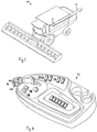
- a combine harvester 10 is shown in front perspective view with its unloading auger tube 12 shown in the stowed position wherein the elongate axis thereof is substantially parallel to the longitudinal axis of the combine 10.
- the invention can be applied to other self-propelled harvesters such as forage harvesters or sugar cane harvesters for example.
- the invention is not limited to auger type unloading conveyors and may extend for example to belt unloaders or blower based systems.
- auger tube 12 is generally cylindrical and at a first end is sealed to an elbow joint 13 which connects the auger tube 12 to an upright conveyor (not shown).
- Auger tube 12 pivots around an upright swing axis 14 which is affected by a freedom of the elbow 13 to pivot around the upright conveyor. It should be understood that the construction of the unloading conveyor itself is known in the art.
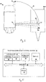
- auger tube 12 is shown in solid-line a deployed position D1 wherein the tube axis extends substantially transverse (90 degrees) to the longitudinal axis of the combine 10.
- the auger tube 12 has freedom to pivot around axis 14 within a movement range indicated by arrow M.
- auger tube 12 can pivot forwardly to an 'over-centre' position D2 which is, in this example, at 104 degrees to the longitudinal axis and represents one end limit of the movement range M.
- a third illustrated deployed position D3 the auger tube 12 resides at 83 degrees to the longitudinal axis.
- the stowed position S is illustrated in Figure 2 in dashed line form and represents the opposite limit of the movement range M.
- a hydraulic actuator 16 is connected in a known manner between the auger tube 12 and a frame member 18 of the combine 10. Hydraulic signals sent to the hydraulic cylinder 16 cause extension and retraction thereof so as to effect deployment and retraction of auger tube 12 as required.
- Sensor 44 comprises a potentiometer having a mechanical linkage connected to auger tube 12 and as illustrated in Figure 3 .
- the potentiometer generates a signal representative of the angular position of auger tube 12, said signal being communicated by a data bus 46 to the controller 42.
- auger tube 12 During unloading, grain is discharged through auger tube 12 into a grain cart 100 driven alongside. To facilitate the driver in 'topping off' the grain in the trailer, the auger tube 12 can be moved within an operating range defined, in this example, between deployed positions D2 and D3.
- the invention can be embodied in unloading conveyors which swing or pivot around non-vertical axes between a deployed position and a stowed position.
- the elongate axis of the conveyor may be inclined to the horizontal.
- the unloading conveyor swing control system embodied in combine 10 includes an operator console 24 shown in Figure 4 and including a rocker switch 26 having an out-button 26a and an in-button 26b.
- An operator can utilise switch 26 to issue commands to the control system 40 wherein depression of out-button 26a equates to a command to increase the deployment angle of the auger tube 12 and depression of in-button 26b equates to a command to reduce the angle of the auger tube 12.
- Figure 5 shows the unloading conveyor swing control system 40 in the form of block diagram wherein the system utilises a data bus 46 to place into communication controller 42, operator console 24, actuator 16 and sensor 44.
- the controller 42 comprise control circuitry 48 which may be embodied as custom made or commercially available processor, a central processing unit or an auxiliary processor among several processors, a semi-conductor based micro-processor (in the form of a micro-chip), a macro processor, one or more applications specific integrated circuits, a plurality of suitably configured digital logic gates, and/or other well-known electrical configurations comprising discrete elements both individually and in various combinations to coordinate the overall operation of the harvester 10.
- control circuitry 48 may be embodied as custom made or commercially available processor, a central processing unit or an auxiliary processor among several processors, a semi-conductor based micro-processor (in the form of a micro-chip), a macro processor, one or more applications specific integrated circuits, a plurality of suitably configured digital logic gates, and/or other well-known electrical configurations comprising discrete elements both individually and in various combinations to coordinate the overall operation of the harvester 10.
- the controller 42 further comprises memory 50.
- the memory 50 may include any one of a combination of volatile memory elements and non-volatile memory elements.
- the memory 50 may store a native operating system, one or more native applications, emulation systems, emulated applications for any of a variety of operating systems and/or emulated hardware platforms, emulated operating systems etc.
- control of the actuator 16 may be implemented through software or firmware executing on a processor of the control circuitry 48.
- the memory 50 may be separate from the controller 42 or may be omitted.
- controller 42 may be in communication with other devices such as the clutch to selectively engage and disengage drive of the unloading auger.
- controller 42 may be in communication with other devices such as the clutch to selectively engage and disengage drive of the unloading auger.
- these other components are not relevant to the invention and further discussion will not be given.
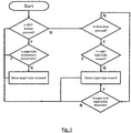
- Controller 42 repeatedly queries whether the cut-button 26a or in-button 26b has been pressed by the operator. If the operator presses out-button 26a then, unless the auger tube 12 is sensed as being at over-centre position D2, then the auger tube 12 is moved outward until either it reaches the end of movement range M or the operator removes pressure from the but button 26a.
- the auger tube 12 is moved inwardly (reduction in deployed angle). If, when the operator removes pressure from in button 26b, the sensed angular position is below the pre-entered threshold, then, in accordance with the invention, the auger tube 12 is automatically swung into the stowed position S. If, however, the sensed angular position is greater than the threshold then movement of the auger tubes ceases.
- rocker switch 26 In operation therefore, during an unloading sequence in which grain is discharged into a cart 100, the operator can use rocker switch 26 to move auger tube 12 within an operating range defined between D2 and D3. When unloading is complete, the operator need only command the movement of auger tube 12 to an angular position below the pre-determined threshold where upon the controller 42 automatically swings the auger tube 12 in to the stowed position S.
- the threshold angle below which the conveyor is automatically stowed can be set by the operator through a suitable user interface device. Alternatively, the threshold angle may be fixed and determined by the manufacturer. In the illustrated example, the threshold angle is shown at D3.
- control circuitry 48 may be configured so that only a single press of out button 26a is required where upon the auger tube 12 is swung to a position within the operating range, position D2 for example.
- rocker switch 26 serves to fine tune the position of auger tube 12 during unloading and also to fully fold and deploy the auger tube.
- controller 42 is implemented at least in part in logic configured as software/firmware (e.g., generally, an application)
- software/firmware e.g., generally, an application
- the application can be stored on a variety of non-transitory computer-readable medium for use by, or in connection with, a variety of computer-related systems or methods.
- a computer-readable medium may comprise an electronic, magnetic, optical, or other physical device or apparatus that may contain or store a computer program for use by or in connection with a computer-related system or method.
- the application may be embedded in a variety of computer-readable mediums for use by, or in connection with, an instruction execution system, apparatus, or device, such as a computer-based system, processor-containing system, or other system that can fetch the instructions from the instruction execution system, apparatus, or device and execute the instructions.
- an instruction execution system, apparatus, or device such as a computer-based system, processor-containing system, or other system that can fetch the instructions from the instruction execution system, apparatus, or device and execute the instructions.
- controller 142 may be implemented with any or a combination of the following technologies, which are all well-known in the art: a discrete logic circuit(s) having logic gates for implementing logic functions upon data signals, an application specific integrated circuit (ASIC) having appropriate combinational logic gates, a programmable gate array(s) (PGA), a field programmable gate array (FPGA), etc.
- ASIC application specific integrated circuit
- PGA programmable gate array
- FPGA field programmable gate array
- the controller 142 is implemented using hardware, software, or a combination of hardware and software.
Landscapes
- Life Sciences & Earth Sciences (AREA)
- Environmental Sciences (AREA)
- Threshing Machine Elements (AREA)
- Harvesting Machines For Root Crops (AREA)
- Ship Loading And Unloading (AREA)
Claims (9)
- Machine de récolte autopropulsée (10) présentant un système de commande de basculement d'un convoyeur de déchargement (40) qui comprend :- un convoyeur de déchargement (12) étant mobile autour d'un axe de pivotement (14) au travers d'une étendue de mouvement entre une première position rangée (S) et une seconde position (D2),- un actionneur (16) raccordé au convoyeur (12) et agencé pour déplacer le convoyeur au travers de l'étendue de mouvement (M) ; et- un dispositif d'interface utilisateur (26) pour la réception de commandes utilisateur visant à déplacer le convoyeur ; caractérisée en ce que le système comprend en outre :- un capteur (44) configuré pour détecter une position angulaire du convoyeur dans l'étendue de mouvement et générer un signal de position représentatif ;- un élément de commande (42) en communication avec le capteur, l'actionneur et le dispositif d'interface utilisateur ; le système de commande (40) étant agencé de sorte que le convoyeur (12) soit automatiquement déplacé dans la première position rangée (S) en réponse à ladite position angulaire tombant sous un angle seuil (D3) prédéterminé et un opérateur libérant le dispositif d'interface utilisateur.
- Machine de récolte selon la revendication 1, dans laquelle le convoyeur (12) est déployé lorsqu'il est dans la seconde position.
- Machine de récolte selon la revendication 2, dans laquelle l'étendue de mouvement (M) est supérieure à 90 degrés.
- Machine de récolte selon une quelconque revendication précédente, dans laquelle l'étendue de mouvement (M) comprend une étendue opérationnelle définie entre l'angle seuil (D3) et la seconde position (D2).
- Machine de récolte selon une quelconque revendication précédente, dans laquelle l'angle seuil (D3) est ajustable à l'utilisateur.
- Machine de récolte selon une quelconque revendication précédente, dans laquelle le dispositif d'interface utilisateur comprend un premier bouton pression (26a) pour augmenter la position angulaire, et un second bouton pression (26b) pour diminuer la position angulaire.
- Machine de récolte selon les revendications 4 et 6, dans laquelle le convoyeur (12) est automatiquement déplacé dans l'étendue opérationnelle en réponse à l'actionnement de l'utilisateur du premier bouton pression (26a).
- Machine de récolte selon une quelconque revendication précédente, dans laquelle le capteur comprend un potentiomètre couplé au convoyeur.
- Machine de récolte selon une quelconque revendication précédente, dans laquelle le convoyeur de déchargement (12) comprend un tube, une vis logée de manière à pouvoir tourner dans le tube et un bec de décharge, le tube étant monté de manière à pouvoir pivoter sur un cadre de la moissonneuse combinée.
Applications Claiming Priority (2)
| Application Number | Priority Date | Filing Date | Title |
|---|---|---|---|
| US201462081872P | 2014-11-19 | 2014-11-19 | |
| PCT/IB2015/001948 WO2016079580A1 (fr) | 2014-11-19 | 2015-10-20 | Système de commande de basculement de convoyeur de déchargement |
Publications (2)
| Publication Number | Publication Date |
|---|---|
| EP3220733A1 EP3220733A1 (fr) | 2017-09-27 |
| EP3220733B1 true EP3220733B1 (fr) | 2018-12-12 |
Family
ID=54754694
Family Applications (1)
| Application Number | Title | Priority Date | Filing Date |
|---|---|---|---|
| EP15802191.5A Not-in-force EP3220733B1 (fr) | 2014-11-19 | 2015-10-20 | Machine de récolte avec systeme de controle de la rotation d'un convoyeur de déchargement |
Country Status (4)
| Country | Link |
|---|---|
| US (1) | US10299433B2 (fr) |
| EP (1) | EP3220733B1 (fr) |
| BR (1) | BR112017010013A2 (fr) |
| WO (1) | WO2016079580A1 (fr) |
Families Citing this family (9)
| Publication number | Priority date | Publication date | Assignee | Title |
|---|---|---|---|---|
| US10863671B2 (en) * | 2017-12-01 | 2020-12-15 | Agco Corporation | Unloading conveyor swing control system |
| US11235931B2 (en) * | 2019-04-05 | 2022-02-01 | The Raymond Corporation | Conveyor cart alignment systems and methods |
| CN110637602A (zh) * | 2019-10-15 | 2020-01-03 | 山东农业工程学院 | 一种全自动跟随收割机、收粮系统及工作方法 |
| CN111357476B (zh) * | 2020-04-21 | 2021-04-30 | 安徽建筑大学 | 一种收割机卸粮筒自动调整位姿装置 |
| US11980134B2 (en) | 2021-03-09 | 2024-05-14 | Deere & Company | Operator commanded placement for control of filling mechanisms |
| US12004449B2 (en) | 2021-03-24 | 2024-06-11 | Deere & Company | Control system for controlling filling mechanisms in communication with a mobile device |
| US11930738B2 (en) * | 2021-06-28 | 2024-03-19 | Deere & Company | Closed loop control of filling mechanisms |
| US11903344B2 (en) | 2021-11-16 | 2024-02-20 | Cnh Industrial America Llc | System and method for controlling unloading system position of an agricultural harvester |
| DE102022103168A1 (de) * | 2022-02-10 | 2023-08-10 | Maschinenfabrik Bernard Krone GmbH & Co. KG | Bedienhebel zur Steuerung einer Komponente, Arbeitsmaschine mit dem Bedienhebel und Verfahren zum Steuern der Komponente |
Family Cites Families (14)
| Publication number | Priority date | Publication date | Assignee | Title |
|---|---|---|---|---|
| DE10021664B4 (de) * | 2000-05-04 | 2004-05-06 | Maschinenfabrik Bernard Krone Gmbh | Erntemaschine, insbesondere selbstfahrender Feldhäcksler |
| US6981833B2 (en) * | 2002-07-19 | 2006-01-03 | Cnh America Llc | Work vehicle with dual mode unloader apparatus and method |
| DE10242164A1 (de) * | 2002-09-10 | 2004-04-01 | Claas Selbstfahrende Erntemaschinen Gmbh | Verfahren zur Steuerung einer Überladeeinrichtung |
| DE102007009666A1 (de) * | 2007-02-22 | 2008-08-28 | Carl Zeiss Microimaging Gmbh | Anordnung zum Befüllen eines Behälters mit Schüttgut |
| US8398469B2 (en) * | 2008-07-09 | 2013-03-19 | Deere & Company | Agricultural work machine having an unloading system for unloading an agricultural product |
| DE102009027245A1 (de) * | 2009-06-26 | 2010-12-30 | Deere & Company, Moline | Steueranordnung zur Kontrolle des Überladens landwirtschaftlichen Ernteguts von einer Erntemaschine auf ein Transportfahrzeug |
| DE102011002071A1 (de) * | 2011-04-15 | 2012-10-18 | Claas Selbstfahrende Erntemaschinen Gmbh | System und Verfahren zur Steuerung der Erntegutüberladung |
| US20130096782A1 (en) * | 2011-10-13 | 2013-04-18 | Agco Corporation | Control Method for a Pivoting Grain Unloading Spout for Use with Combine Harvesters |
| US8626406B2 (en) * | 2011-12-22 | 2014-01-07 | Deere & Company | Method and system for transferring material between vehicles |
| US9861040B2 (en) * | 2012-02-10 | 2018-01-09 | Deere & Company | Method and stereo vision system for facilitating the unloading of agricultural material from a vehicle |
| DE102014105643B4 (de) * | 2013-04-22 | 2026-01-22 | Carnegie Mellon University | System und Verfahren zur Verbesserung der Robustheit eines automatisierten Entladesystems |
| DE102013012026A1 (de) * | 2013-07-19 | 2015-01-22 | Claas Selbstfahrende Erntemaschinen Gmbh | Fahrzeugverbund, Vorrichtung und Verfahren zu dessen Koordination |
| GB2517049B (en) | 2013-07-28 | 2019-09-11 | Deere & Co | Artificial intelligence for detecting and filling void areas of agricultural commodity containers |
| DE102014100136A1 (de) * | 2014-01-08 | 2015-07-09 | Claas Selbstfahrende Erntemaschinen Gmbh | Erntevorrichtung |
-
2015
- 2015-10-20 EP EP15802191.5A patent/EP3220733B1/fr not_active Not-in-force
- 2015-10-20 BR BR112017010013A patent/BR112017010013A2/pt active Search and Examination
- 2015-10-20 WO PCT/IB2015/001948 patent/WO2016079580A1/fr not_active Ceased
- 2015-10-20 US US15/528,176 patent/US10299433B2/en not_active Expired - Fee Related
Non-Patent Citations (1)
| Title |
|---|
| None * |
Also Published As
| Publication number | Publication date |
|---|---|
| US10299433B2 (en) | 2019-05-28 |
| BR112017010013A2 (pt) | 2018-01-02 |
| EP3220733A1 (fr) | 2017-09-27 |
| US20180310475A1 (en) | 2018-11-01 |
| WO2016079580A1 (fr) | 2016-05-26 |
Similar Documents
| Publication | Publication Date | Title |
|---|---|---|
| EP3220733B1 (fr) | Machine de récolte avec systeme de controle de la rotation d'un convoyeur de déchargement | |
| EP1344445B2 (fr) | Traitement d'images pour système de contrôle de goulotte de décharge | |
| US8606454B2 (en) | System and method for synchronized control of a harvester and transport vehicle | |
| US20130096782A1 (en) | Control Method for a Pivoting Grain Unloading Spout for Use with Combine Harvesters | |
| US9002591B2 (en) | Harvester spout control system and method | |
| US10091935B2 (en) | Swathboard control with windrow merger attachment | |
| CA3060890C (fr) | Systeme de commande des fonctions d`un chariot a cereales programmable | |
| RU2348142C2 (ru) | Способ и устройство управления работой перегрузочного устройства сельхозмашины и сельхозмашина | |
| US20100332051A1 (en) | Control Arrangement For Controlling The Transfer Of Agricultural Crop From A Harvesting Machine To A Transport Vehicle | |
| RU2015137963A (ru) | Способ управления процессом перевалки | |
| CN113924398B (zh) | 负载操纵机器和控制负载操纵机器的方法 | |
| JP7142433B2 (ja) | 収穫機制御システム | |
| US20160207601A1 (en) | Water Sport Device Having a Fin | |
| US12302789B2 (en) | Combine and self-driving method | |
| US10863671B2 (en) | Unloading conveyor swing control system | |
| JP2008182945A (ja) | 穀粒排出システム | |
| JP2023043362A (ja) | 自動走行方法、作業車両及び自動走行システム | |
| JPH09294449A (ja) | コンバイン | |
| JP2008161085A (ja) | コンバインの穀粒排出装置 | |
| JP2001178253A (ja) | 穀粒排出装置 | |
| JP4054440B2 (ja) | 作業車両における穀稈搬送装置 | |
| JP5060140B2 (ja) | コンバイン | |
| JP3596990B2 (ja) | コンバインにおける穀粒排出装置 | |
| JP2004236593A (ja) | 排出オ−ガの操作装置 | |
| JP2018173044A (ja) | 作業機 |
Legal Events
| Date | Code | Title | Description |
|---|---|---|---|
| STAA | Information on the status of an ep patent application or granted ep patent |
Free format text: STATUS: THE INTERNATIONAL PUBLICATION HAS BEEN MADE |
|
| PUAI | Public reference made under article 153(3) epc to a published international application that has entered the european phase |
Free format text: ORIGINAL CODE: 0009012 |
|
| STAA | Information on the status of an ep patent application or granted ep patent |
Free format text: STATUS: REQUEST FOR EXAMINATION WAS MADE |
|
| 17P | Request for examination filed |
Effective date: 20170619 |
|
| AK | Designated contracting states |
Kind code of ref document: A1 Designated state(s): AL AT BE BG CH CY CZ DE DK EE ES FI FR GB GR HR HU IE IS IT LI LT LU LV MC MK MT NL NO PL PT RO RS SE SI SK SM TR |
|
| AX | Request for extension of the european patent |
Extension state: BA ME |
|
| DAV | Request for validation of the european patent (deleted) | ||
| DAX | Request for extension of the european patent (deleted) | ||
| GRAP | Despatch of communication of intention to grant a patent |
Free format text: ORIGINAL CODE: EPIDOSNIGR1 |
|
| STAA | Information on the status of an ep patent application or granted ep patent |
Free format text: STATUS: GRANT OF PATENT IS INTENDED |
|
| INTG | Intention to grant announced |
Effective date: 20180606 |
|
| GRAS | Grant fee paid |
Free format text: ORIGINAL CODE: EPIDOSNIGR3 |
|
| GRAA | (expected) grant |
Free format text: ORIGINAL CODE: 0009210 |
|
| STAA | Information on the status of an ep patent application or granted ep patent |
Free format text: STATUS: THE PATENT HAS BEEN GRANTED |
|
| AK | Designated contracting states |
Kind code of ref document: B1 Designated state(s): AL AT BE BG CH CY CZ DE DK EE ES FI FR GB GR HR HU IE IS IT LI LT LU LV MC MK MT NL NO PL PT RO RS SE SI SK SM TR |
|
| REG | Reference to a national code |
Ref country code: GB Ref legal event code: FG4D |
|
| REG | Reference to a national code |
Ref country code: CH Ref legal event code: EP |
|
| REG | Reference to a national code |
Ref country code: AT Ref legal event code: REF Ref document number: 1074768 Country of ref document: AT Kind code of ref document: T Effective date: 20181215 |
|
| REG | Reference to a national code |
Ref country code: DE Ref legal event code: R096 Ref document number: 602015021611 Country of ref document: DE |
|
| REG | Reference to a national code |
Ref country code: IE Ref legal event code: FG4D |
|
| REG | Reference to a national code |
Ref country code: NL Ref legal event code: MP Effective date: 20181212 |
|
| REG | Reference to a national code |
Ref country code: LT Ref legal event code: MG4D |
|
| PG25 | Lapsed in a contracting state [announced via postgrant information from national office to epo] |
Ref country code: BG Free format text: LAPSE BECAUSE OF FAILURE TO SUBMIT A TRANSLATION OF THE DESCRIPTION OR TO PAY THE FEE WITHIN THE PRESCRIBED TIME-LIMIT Effective date: 20190312 Ref country code: NO Free format text: LAPSE BECAUSE OF FAILURE TO SUBMIT A TRANSLATION OF THE DESCRIPTION OR TO PAY THE FEE WITHIN THE PRESCRIBED TIME-LIMIT Effective date: 20190312 Ref country code: LT Free format text: LAPSE BECAUSE OF FAILURE TO SUBMIT A TRANSLATION OF THE DESCRIPTION OR TO PAY THE FEE WITHIN THE PRESCRIBED TIME-LIMIT Effective date: 20181212 Ref country code: ES Free format text: LAPSE BECAUSE OF FAILURE TO SUBMIT A TRANSLATION OF THE DESCRIPTION OR TO PAY THE FEE WITHIN THE PRESCRIBED TIME-LIMIT Effective date: 20181212 Ref country code: LV Free format text: LAPSE BECAUSE OF FAILURE TO SUBMIT A TRANSLATION OF THE DESCRIPTION OR TO PAY THE FEE WITHIN THE PRESCRIBED TIME-LIMIT Effective date: 20181212 Ref country code: HR Free format text: LAPSE BECAUSE OF FAILURE TO SUBMIT A TRANSLATION OF THE DESCRIPTION OR TO PAY THE FEE WITHIN THE PRESCRIBED TIME-LIMIT Effective date: 20181212 Ref country code: FI Free format text: LAPSE BECAUSE OF FAILURE TO SUBMIT A TRANSLATION OF THE DESCRIPTION OR TO PAY THE FEE WITHIN THE PRESCRIBED TIME-LIMIT Effective date: 20181212 |
|
| REG | Reference to a national code |
Ref country code: AT Ref legal event code: MK05 Ref document number: 1074768 Country of ref document: AT Kind code of ref document: T Effective date: 20181212 |
|
| PG25 | Lapsed in a contracting state [announced via postgrant information from national office to epo] |
Ref country code: AL Free format text: LAPSE BECAUSE OF FAILURE TO SUBMIT A TRANSLATION OF THE DESCRIPTION OR TO PAY THE FEE WITHIN THE PRESCRIBED TIME-LIMIT Effective date: 20181212 Ref country code: SE Free format text: LAPSE BECAUSE OF FAILURE TO SUBMIT A TRANSLATION OF THE DESCRIPTION OR TO PAY THE FEE WITHIN THE PRESCRIBED TIME-LIMIT Effective date: 20181212 Ref country code: RS Free format text: LAPSE BECAUSE OF FAILURE TO SUBMIT A TRANSLATION OF THE DESCRIPTION OR TO PAY THE FEE WITHIN THE PRESCRIBED TIME-LIMIT Effective date: 20181212 Ref country code: GR Free format text: LAPSE BECAUSE OF FAILURE TO SUBMIT A TRANSLATION OF THE DESCRIPTION OR TO PAY THE FEE WITHIN THE PRESCRIBED TIME-LIMIT Effective date: 20190313 |
|
| PG25 | Lapsed in a contracting state [announced via postgrant information from national office to epo] |
Ref country code: NL Free format text: LAPSE BECAUSE OF FAILURE TO SUBMIT A TRANSLATION OF THE DESCRIPTION OR TO PAY THE FEE WITHIN THE PRESCRIBED TIME-LIMIT Effective date: 20181212 |
|
| PG25 | Lapsed in a contracting state [announced via postgrant information from national office to epo] |
Ref country code: CZ Free format text: LAPSE BECAUSE OF FAILURE TO SUBMIT A TRANSLATION OF THE DESCRIPTION OR TO PAY THE FEE WITHIN THE PRESCRIBED TIME-LIMIT Effective date: 20181212 Ref country code: IT Free format text: LAPSE BECAUSE OF FAILURE TO SUBMIT A TRANSLATION OF THE DESCRIPTION OR TO PAY THE FEE WITHIN THE PRESCRIBED TIME-LIMIT Effective date: 20181212 Ref country code: PL Free format text: LAPSE BECAUSE OF FAILURE TO SUBMIT A TRANSLATION OF THE DESCRIPTION OR TO PAY THE FEE WITHIN THE PRESCRIBED TIME-LIMIT Effective date: 20181212 Ref country code: PT Free format text: LAPSE BECAUSE OF FAILURE TO SUBMIT A TRANSLATION OF THE DESCRIPTION OR TO PAY THE FEE WITHIN THE PRESCRIBED TIME-LIMIT Effective date: 20190412 |
|
| PG25 | Lapsed in a contracting state [announced via postgrant information from national office to epo] |
Ref country code: EE Free format text: LAPSE BECAUSE OF FAILURE TO SUBMIT A TRANSLATION OF THE DESCRIPTION OR TO PAY THE FEE WITHIN THE PRESCRIBED TIME-LIMIT Effective date: 20181212 Ref country code: SM Free format text: LAPSE BECAUSE OF FAILURE TO SUBMIT A TRANSLATION OF THE DESCRIPTION OR TO PAY THE FEE WITHIN THE PRESCRIBED TIME-LIMIT Effective date: 20181212 Ref country code: RO Free format text: LAPSE BECAUSE OF FAILURE TO SUBMIT A TRANSLATION OF THE DESCRIPTION OR TO PAY THE FEE WITHIN THE PRESCRIBED TIME-LIMIT Effective date: 20181212 Ref country code: IS Free format text: LAPSE BECAUSE OF FAILURE TO SUBMIT A TRANSLATION OF THE DESCRIPTION OR TO PAY THE FEE WITHIN THE PRESCRIBED TIME-LIMIT Effective date: 20190412 Ref country code: SK Free format text: LAPSE BECAUSE OF FAILURE TO SUBMIT A TRANSLATION OF THE DESCRIPTION OR TO PAY THE FEE WITHIN THE PRESCRIBED TIME-LIMIT Effective date: 20181212 |
|
| REG | Reference to a national code |
Ref country code: DE Ref legal event code: R097 Ref document number: 602015021611 Country of ref document: DE |
|
| PLBE | No opposition filed within time limit |
Free format text: ORIGINAL CODE: 0009261 |
|
| STAA | Information on the status of an ep patent application or granted ep patent |
Free format text: STATUS: NO OPPOSITION FILED WITHIN TIME LIMIT |
|
| PG25 | Lapsed in a contracting state [announced via postgrant information from national office to epo] |
Ref country code: DK Free format text: LAPSE BECAUSE OF FAILURE TO SUBMIT A TRANSLATION OF THE DESCRIPTION OR TO PAY THE FEE WITHIN THE PRESCRIBED TIME-LIMIT Effective date: 20181212 Ref country code: AT Free format text: LAPSE BECAUSE OF FAILURE TO SUBMIT A TRANSLATION OF THE DESCRIPTION OR TO PAY THE FEE WITHIN THE PRESCRIBED TIME-LIMIT Effective date: 20181212 Ref country code: SI Free format text: LAPSE BECAUSE OF FAILURE TO SUBMIT A TRANSLATION OF THE DESCRIPTION OR TO PAY THE FEE WITHIN THE PRESCRIBED TIME-LIMIT Effective date: 20181212 |
|
| 26N | No opposition filed |
Effective date: 20190913 |
|
| PGFP | Annual fee paid to national office [announced via postgrant information from national office to epo] |
Ref country code: DE Payment date: 20191021 Year of fee payment: 5 |
|
| PG25 | Lapsed in a contracting state [announced via postgrant information from national office to epo] |
Ref country code: TR Free format text: LAPSE BECAUSE OF FAILURE TO SUBMIT A TRANSLATION OF THE DESCRIPTION OR TO PAY THE FEE WITHIN THE PRESCRIBED TIME-LIMIT Effective date: 20181212 |
|
| PG25 | Lapsed in a contracting state [announced via postgrant information from national office to epo] |
Ref country code: MC Free format text: LAPSE BECAUSE OF FAILURE TO SUBMIT A TRANSLATION OF THE DESCRIPTION OR TO PAY THE FEE WITHIN THE PRESCRIBED TIME-LIMIT Effective date: 20181212 |
|
| REG | Reference to a national code |
Ref country code: CH Ref legal event code: PL |
|
| PG25 | Lapsed in a contracting state [announced via postgrant information from national office to epo] |
Ref country code: CH Free format text: LAPSE BECAUSE OF NON-PAYMENT OF DUE FEES Effective date: 20191031 Ref country code: LI Free format text: LAPSE BECAUSE OF NON-PAYMENT OF DUE FEES Effective date: 20191031 Ref country code: LU Free format text: LAPSE BECAUSE OF NON-PAYMENT OF DUE FEES Effective date: 20191020 |
|
| REG | Reference to a national code |
Ref country code: BE Ref legal event code: MM Effective date: 20191031 |
|
| PG25 | Lapsed in a contracting state [announced via postgrant information from national office to epo] |
Ref country code: BE Free format text: LAPSE BECAUSE OF NON-PAYMENT OF DUE FEES Effective date: 20191031 |
|
| GBPC | Gb: european patent ceased through non-payment of renewal fee |
Effective date: 20191020 |
|
| PG25 | Lapsed in a contracting state [announced via postgrant information from national office to epo] |
Ref country code: FR Free format text: LAPSE BECAUSE OF NON-PAYMENT OF DUE FEES Effective date: 20191031 Ref country code: IE Free format text: LAPSE BECAUSE OF NON-PAYMENT OF DUE FEES Effective date: 20191020 Ref country code: GB Free format text: LAPSE BECAUSE OF NON-PAYMENT OF DUE FEES Effective date: 20191020 |
|
| REG | Reference to a national code |
Ref country code: DE Ref legal event code: R119 Ref document number: 602015021611 Country of ref document: DE |
|
| PG25 | Lapsed in a contracting state [announced via postgrant information from national office to epo] |
Ref country code: CY Free format text: LAPSE BECAUSE OF FAILURE TO SUBMIT A TRANSLATION OF THE DESCRIPTION OR TO PAY THE FEE WITHIN THE PRESCRIBED TIME-LIMIT Effective date: 20181212 |
|
| PG25 | Lapsed in a contracting state [announced via postgrant information from national office to epo] |
Ref country code: DE Free format text: LAPSE BECAUSE OF NON-PAYMENT OF DUE FEES Effective date: 20210501 Ref country code: MT Free format text: LAPSE BECAUSE OF FAILURE TO SUBMIT A TRANSLATION OF THE DESCRIPTION OR TO PAY THE FEE WITHIN THE PRESCRIBED TIME-LIMIT Effective date: 20181212 Ref country code: HU Free format text: LAPSE BECAUSE OF FAILURE TO SUBMIT A TRANSLATION OF THE DESCRIPTION OR TO PAY THE FEE WITHIN THE PRESCRIBED TIME-LIMIT; INVALID AB INITIO Effective date: 20151020 |
|
| PG25 | Lapsed in a contracting state [announced via postgrant information from national office to epo] |
Ref country code: MK Free format text: LAPSE BECAUSE OF FAILURE TO SUBMIT A TRANSLATION OF THE DESCRIPTION OR TO PAY THE FEE WITHIN THE PRESCRIBED TIME-LIMIT Effective date: 20181212 |